浙江电信海思终端锁频指导书
HiStudio使用说明
1.软件的安装
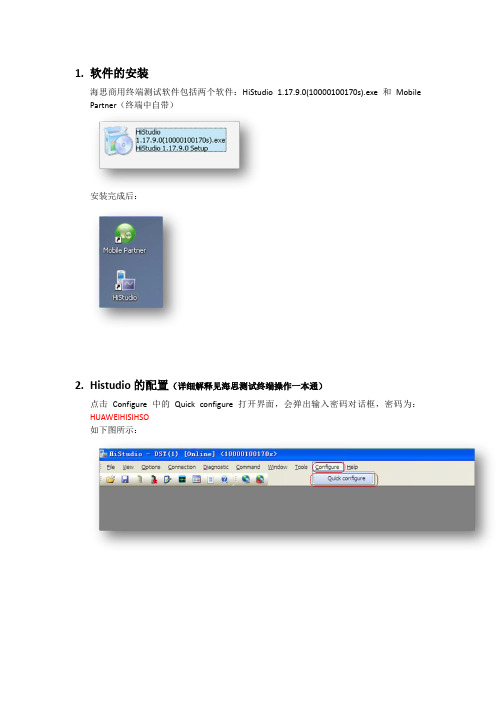
海思商用终端测试软件包括两个软件:HiStudio 1.17.9.0(10000100170s).exe和Mobile Partner(终端中自带)
安装完成后:
2.Histudio的配置(详细解释见海思测试终端操作一本通)
点击Configure中的Quick configure打开界面,会弹出输入密码对话框,密码为:HUAWEIHISIHSO
如下图所示:
1)点UPDATA
2)Hard USIM
3)SMC :OPEN
4)Support feature:室内选择band40,室外band38 5)LOCK Info设置可以不设置,即为:Lock None;6)Ps Key 不用设置
7)OK
也可以根据频点,频段,小区PCI等条件设置。
3.Mobile partner的配置
点击mobile partner → TOOLS → profile management 如下图:
4.设备的连接
1)Start:连接终端,设置端口
2)LTE start:运行程序,显示后台消息
MP才可信号强度,
设置SSCOM32: g_ulSmcControl=1
进行拨号上网(打开mobile partner 进行连接)
输入g_ulSmcControl=1 命令后打开mobile partner,下方会出现CHN08的网络,点击
connect
设置拨号连接成功后可以看到实时的RSRP,SINR,PCI,thoughtput等,见下图:。
海思Android安全方案 使用指南

增加 emmc 支持,修改 init.rc 文件和 system_sign 分区改 名为 systemsign
修改适配 HiSTBAndroidV500R001C00SPC050 版本支持功 能说明
增加对 Hi3716MV300 支持说明
增加 APK 管控方案
第一次临时发布
iv
海思专有和保密信息 版权所有 © 深圳市海思半导体有限公司
海思Android安全方案 使用指南
文档版本 发布日期
02 2014-03-12
版权所有 © 深圳市海思半导体有限公司 2014。保留一切权利。
非经本公司书面许可,任何单位和个人不得擅自摘抄、复制本文档内容的部分或全部,并不得以任 何形式传播。
商标声明
、
、海思和其他海思商标均为深圳市海思半导体有限公司的商标。
1.1 概述..............................................................................................................................................................1-1 1.2 高安方案软件设计......................................................................................................................................1-1
SIM7100模块锁频方法
SIM7100CE锁频FAQ锁频方法选择原则:1、若为高通芯片,则使用QXDM/QPST方法锁频,部分海思芯片终端打开高通设置后也能被QXDM识别一、Q XDM锁band方法注意:使用前确保QXDM/QPST为适配版本,太老的版本可能无法使用1.1打开NVbrowser打开QXDM,连接相应端口后,进入view->new->common->NV browser里1.2修改6828号的NV值在NV Broswer里选LTE category,找到ID为6828的项目,更改lte_bc_config的值,这是一个64位2进制的值,每一位代表支不支持该band,1代表支持0代表不支持1.3NV配置值说明以G620为例,G620默认支持band1/3/41,所以初始默认的lte_bc_config值为0x10000000005(10进制为1099511627781)若想让G620只支持TDD,锁住TDD功能,即让G620锁住band41,把lte_bc_config的值改为0x10000000000即可。
二、QPST锁频方法2.1 打开EFS explorer确保QPST能识别手机端口后,在开始菜单进入QPST->EFS explorer,连接相应的手机端口,建立连接2.2 编写camp_band_earfcn文件使用UltraEdit打开camp_band_earfcn文件,点hex按钮换算16进制显示,根据实际项目需要编写该值。
说明:高4位代表band号,低4位代表频点,但是顺序是CDBA,如40340频点换算成16进制是9D94,则写入29 00 94 9D.2.3写入camp_band_earfcn文件在EFS explorer里进入nv/item_files/modem/lte目录并新建ML1目录,将修改好的camp_band_earfcn文件丢入该目录即可,若想取消锁频,删除ML1目录的该文件即可三、HISTUDIO锁频方法3.1用串口工具发送AT命令打开调试端口终端在出厂时只开放了PC UI Interface端口,使用串口工具或者histudio自带的AT工具发送以下命令后,重启终端即可识别所有调试端口AT^OPWORD=GL04P2012AT^SETPORT="A1,A2;14,13,12,A,3,16,5,A1,A2"at^tmode=33.2连接相应端口后,修改NV值锁频如下图点connection进入设置,上一步开启了相应端口后会自动读取出来。
HNC-818-用户操作说明书(操作)-1.24.00

前言本系列说明书全面地介绍了HNC-818数控系统的特性、系统组成、各部分的系统命令及其使用、操作步骤、用户编程方法及示例等,是用户快速学习和使用本系统的基本说明书。
本说明书的更新和升级事宜,由武汉华中数控股份有限公司授权并组织实施。
未经本公司授权或书面许可,任何单位或个人无权对本说明书内容进行修改或更正,本公司概不负责由此而造成的客户损失。
HNC-818数控系统用户说明书中,我们将尽力叙述各种与该系统操作相关的事件。
由于篇幅限制及产品开发定位等原因,不能也不可能对系统中所有不必做或不能做的事件进行详细的叙述。
因此,本说明书中没有特别描述的事件均可视为“不可能”或“不允许”的事件。
此说明书的版权归武汉华中数控股份有限公司,任何单位与个人进行出版或复印均属于非法行为,我公司将追究其法律责任。
HNC-818数控系统用户说明书目录目录前言 (i)目录 (iii)I概述 (1)1概述 ........................................................................................................................... 错误!未定义书签。
2规格表 ....................................................................................................................... 错误!未定义书签。
II操作 . (3)1操作设备 (4)1.1显示及操作面板 (5)1.2NC键盘 (6)1.3机床控制面板 (7)1.4手持单元 (8)1.5系统操作面板 (9)2上电、关机、急停 (10)2.1上电 (11)2.2复位 (12)2.3返回机床零点 (13)2.4急停 (14)2.5超程解除 (15)2.6关机 (16)3机床手动操作 (17)3.1坐标轴移动 (18)3.2主轴控制 (21)3.3机床锁住、Z轴锁住 (23)3.4手动数据输入(MDI)运行 (24)4设置 (26)4.1刀具管理 (27)4.2坐标系的设置 (31)4.3相对清零 (33)4.4参数 (34)5程序编辑与管理 (56)5.1程序选择 (57)5.2程序编辑 (61)5.3程序管理 (64)5.4任意行 (66)5.5程序校验 (71)5.6停止运行 (72)5.7重运行 (73)5.8工艺文件 (74)目录 HNC-818数控系统用户说明书5.9工件测量功能 (76)6运行控制 (79)6.1启动、暂停、中止 (80)6.2空运行 (81)6.3程序跳段 (82)6.4选择停 (83)6.5单段运行 (84)6.6加工断点保存与恢复 (85)6.7运行时干预 (88)7位置信息 (90)7.1坐标显示 (91)7.2正文显示 (92)7.3图形显示 (93)7.4联合显示 (95)8诊断 (96)8.1系统Logo界面导入功能 (97)8.2报警显示 (99)8.3报警历史 (100)8.4梯图监控 (103)8.5输入输出 (108)8.6状态显示 (109)8.7宏变量 (110)8.8伺服调整 (111)8.9加工信息 (123)8.10版本 (124)9用户使用与维护信息 (126)9.1环境条件 (127)9.2接地 (128)9.3供电条件 (129)9.4风扇过滤网清尘 (130)9.5长时间闲置后使用 (131)ivI概述11. 概述 HNC-818数控系统用户说明书本说明书叙述如下型号的数控系统:类型名缩略词HNC-818A铣削数控单元HNC-818A-MUHNC-818B铣削数控单元HNC-818B-MU2II操作31. 操作设备 HNC-818数控系统用户说明书1 操作设备本章主要介绍HNC-818数控系统的操作台以及系统操作界面:显示及操作面板NC键盘机床控制面板手持单元系统操作界面4HNC-818数控系统用户说明书 1. 操作设备1.1显示及操作面板HNC-818A-MU8.4寸彩色液晶显示器(分辨率为800×600);HNC-818B-MU10.4寸彩色液晶显示器(分辨率为800×600);1、厂家商标LOGO区;2、显示屏区3、USB接口4、以太网接口5、软键6、功能键区7、光标区8、字母及数字键盘区51. 操作设备HNC-818数控系统用户说明书1.2NC键盘NC键盘包括精简型MDI键盘、主菜单键和功能键,主要用于零件程序的编制、参数输入、MDI及系统管理操作等。
Probe锁频指导
一:锁频步骤
1.正常连接设备
2.依次打开Test->Forcing Function->LTE Forcing Feature,如下图:
3.锁频:
1:当前服务小区的信息
2.锁频选项(较常用的为Lock EARFCN即锁频点)
3.需要锁的目的频点
4.点击Apply进行锁频,如6提示,即锁频成功,此时要断开设备,重启mifi才能生效,如提示Timeout,锁频失败,继续点击Apply,直到提示成功为止。
5.点击Reset进行解锁,如6提示即解锁成功,此时需要断开设备,重启mifi。
二、点击后在此界面有四种(Probe3.6)或三种(Probe3.5)锁频方式
1、LOCK Band 为锁频段目前联通用的是3 和41,移动用的是38、39、40
2、Lock EARFCN 为锁频点较经常使用
3、Lock EARFCN and PCI 为锁频点和PCI
4、Lock PLMN 为锁运营商一般使用的比较少
三、锁频的时候点击Lock EARFCN 在EARFCN里面填写需要锁频的频点号。
例如锁38350或者37900 填完后点击Apply ,当界面弹出如下界面时表示已锁频成功,此时需断开设备,重启MIFI后,即锁频完成。
若测试完后恢复自由模式,则步骤一样,在上面步骤时点Reset 直到弹出如下一样界面后重启MIFI就完成自由模式。
注意:有时候连接设备后点击Apply会提示超时,则需要在PROBE上断开设备,重新连接设备后再锁频即可,也可以多点击几次Apply,直到下面提示,The operation is Successful。
才能锁频成功。
切记:测试结束要立即解锁。
海思商用终端操作指导
海思商用终端操作指导拟制海思团队日期2011-1-12 审核日期批准日期华为技术有限公司版权所有侵权必究(DVP05T04 V2.8 / 仅供内部使用)修订记录目录1前言 (4)2P C端驱动安装 (4)3简化版HSO使用说明 (10)3.1入网配置 (16)3.1.1配置Quick configure (16)4M obile Partner使用介绍 (20)4.1Mobile Partner安装升级 (20)4.2Mobile Partner 简介 (21)4.2.1功能简介 (21)4.2.2界面简介 (21)4.3操作指导 (26)4.3.1操作步骤 (26)4.4Mobile Partner日志使用 (28)4.5注意事项 (29)1前言1.1 HSO版本更新记录B180:更新快速配置功能,对支持的Band中上下选择不一致的问题进行改进1.2 HSO安装标识海思Dongle的操作主要通过HiStudio工具完成。
如果没有HiStudio工具,可通过Mobile Partner连接入网。
本操作指导书主要介绍了HSO的使用界面、常规配置,并对Mobile Partner等操作进行说明,后续会陆续更新FAQ等信息。
2PC端驱动安装注意:有两种方案,一种是使用海思之前提供的单独的驱动软件,例如:Windows-5.06.08.00;另一种是使用数据卡缓存中携带的Mobile Connect安装包,其中包括驱动和Mobile Partner两个软件。
安装Mobile Partner即可。
在使用终端之前,最好先安装WinXP补丁(如果不确认系统是否已经安装的情况下)。
2.1 单独驱动安装2.1.1 驱动获取可以向海思Dongle指定的接口人获取。
驱动目录结构如下:2.1.2 驱动安装断开Dongle与PC的连接,点击DriverSetup.exe,等待一会安装完成。
注意此时没有任何提示。
如果先前已经安装过老版本的驱动,需要先执行DriverUninstall.exe完成后,等待一分钟左右;再执行DriverSetup.exe,再等待一分钟左右。
FAQ常用路测终端锁频指导书
名称密级Confidentiality level 常用路测终端锁频指导书内部公开版本Total 10 pages 共10页V1.00常用路测终端锁频指导书拟制: 李斌00163755 日期:2010-5-15审核: 日期:批准: 日期:华为技术有限公司版权所有侵权必究目录Table of Contents1 目的 (3)2 常用终端锁频适用方法 (3)3 具体锁频方法 (3)3.1 通过PHU锁频 (3)3.1.1 GSM网络下锁频点 (3)3.1.2 GSM网络下锁频段 (6)3.1.3 UMTS网络下锁频 (8)3.2 通过进入手机终端工程模式锁频 (9)3.3 通过AT命令锁频 (9)常用路测终端锁频指导书1目的本文档主要介绍了路测小组常用的几种锁频方法,供测试开发人员参考和学习,提高并探讨对锁频知识点的认识。
GSM制式包括锁频点和锁频段。
WCDMA制式包括锁指定频点和锁扰码。
锁频频点(频段)后可以使终端只工作在指定的频点(频段)上。
2常用终端锁频适用方法并不是所有的终端这3种锁频方式都适用。
一般情况下,对手机终端推荐锁频顺序为使用PHU进行锁频(操作简单易懂,且不需要电脑,最易于实现),使用工程模式锁频(需要知道进入工程模式的特定号码),使用AT命令锁频(需要使用电脑操作);而对于数据卡一类的终端,因为没有显示装置,一般则使用AT命令进行锁频操作。
3具体锁频方法3.1通过PHU锁频3.1.1GSM网络下锁频点(1)GSM下的锁频点就是锁主BCCH频点。
主要用于单站验证且只有在空闲态下才能锁频点,业务态下不能锁频点。
锁频之前先要清楚手机所处于的服务&邻小区信息,服务&邻小区信息会变化,但当静止状态时,有一部分小区会长时间稳定存在于服务&邻小区列表中。
选择服务&邻小区的BCCH锁定,锁定成功之后手机仍然能够处于GSM网络覆盖下。
如果随便输入一个频点锁定,则锁定成功手机不能处于网络的覆盖下。
海思LoRa无线温控器说明书
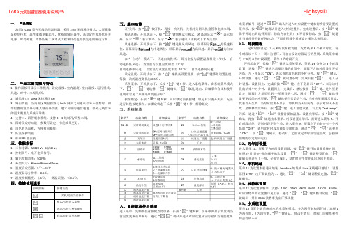
风速选择:开机状态下,按“ ”键选择风机风速。屏幕显示
为低速档
位,屏幕显示
为中速档位,屏幕显示
为高风速,显示
为自动
风速。
在“ 自动” 模式下, 风速自动换档。 即当室温与设置温度相差 1℃时, 自
动选择低风速; 当室温与设置温度相差 3℃时,
自动选择中风速; 当室温与设置温度相差 5℃时, 自动选择高风速。
闪烁,通过“ ” “ ”设置需要的温度,设置完毕后,按“ ”键
确认,再按“ ”键退出本菜单。时段设置完毕后,需要进入菜单 9,开
启时段功能,否则时段不会生效。进入菜单 9,屏幕左下角有会有一个闪
烁的“OFF”,表明此时时段功能是关闭状态,通过“ ” “ ”选择到
“ON”, 按“ ”键确认,修改后,之前设定的时段功能生效,会按照
为 25。进入菜单,“ ” “ ”键调整需要的信道值,“ ”键确认修改。
6.12 恢复出厂设置
菜单 23 为恢复出厂默认设置,“ ”键进入菜单,“ ”键调整数值到“08”,
“ ”键确认生效,温控器重新启动,所有配置全部恢复出厂默认设置。
6.13 背光亮度 菜单 26 为设置液晶屏背光亮度,分为高中低亮度三挡,默认为 低亮度。
设定温度:开机状态下,按“ ”键提高设置温度,按“ ”键降低设置温度,
每按一次的温度变化为 0.5℃。
系统菜单:开机状态下,长按“ ”键 5 秒,进入系统菜单;在系统菜单模式
下,“ ” “ ”键选择,“ ”键确认,“ ”取消/退出。详细菜单含义和使用
说明请看见“系统菜单功能介绍”。
按键锁定:长按“ ”键 5 秒,可以锁定面板按键,锁定后只能开关机,无法
三、性能指标
1、工作电源:AC220 V,50/60Hz; 2、控制信号:电开电关信号; 3、输出控制功率:500W; 4、外型尺寸:86mmx86mmx37mm; 5、温度设定范围:5℃~45℃; 6、温度显示分辨率:0.5℃; 7、温度控制精度:±1℃; 测温误差:≤0.5℃;
海思K3(Hi3611)平台设计手册
HISILICON Confidential
Page 2
1.设计概述
1.1 规格定义 1.2 性能参数
HISILICON Confidential
Page 3
1.1规格定义
• • • • • • • • • • 主芯片 HI3611 + PNX5209 操作系统Windows Mobile 6.1 蓝牙支持BT2.0+EDR WiFi802.11b/g GPS支持AGPS 无线网络GSM/GPRS/EDGE 频段GSM/GPRS/EDGE 850/900/1800/1900 主屏参数彩屏260K色TFT,240×320像素,2.8英寸触摸屏 摄像头主摄像头200万像素CMOS传感器内置摄像头 电池1000mAh锂电池
Page 9
2.1外设单元介绍-LCM
LCM
LCD backlight
1、LCD DATA是采用18bit RGB接口包括:PCLK、VSYNC、HSYNC、DE、RESET、18bit data line,SPI等 2、LCM Driver IC采用HX8347,IO电压及VCC为2.8V 3、LCM模组内部touch panel的干扰选型时需要注意。 4、背光IC采用串联及并联驱动方式都可以, 都是使用3611的PWM输出信号来实现背光调节, 要注意HI3611 PWM输 出的高低电平(高电平最低1.5V,低电平最高0.3V)需求 5、背光ICPWM频率输入范围为要考虑到背光ICPWM频率输入范围为要考虑到音频噪声的影响,开关频率尽量不要落 在2K以内。目前海思参考设计使用的是80KHz,后面可以通过调节注册表而不用修改代码来调整到可以接受的范围。
HISILICON Confidential
Page 19
shure axt600 频谱管理器 用户手册说明书
AXT600 Spectrum ManagerManual for the Shure Axient Spectrum Manager (AXT600). Version: 4 (2019-L)Table of ContentsAXT600Spectrum Manager 3简要说明3特性 3前面板4后面板 5连接天线6安装说明6主菜单屏幕6数据显示屏幕 8频谱管理器与接收机的连网8自动 IP 地址分配 9手动 IP 地址 9设备重置 9故障排除 9网络访问控制 10射频协调向导10 All New 10 Update Freqs 10 Update Devices 10使用 All New 向导选项进行系统设置11排除12输入排除项目 12事件日志12频谱监控13备用频率监控 13侦听 13扫描 14风扇速度设置15固件更新15规格15扫描时间 17 RF 输入 17联网 18附件18提供的附件 18 Information to the user19重要安全事项! 19适用于所有耳机的警告! 20警告 21认证21AXT600Spectrum Manager 简要说明Axient 频谱管理器是一款功能强大的工具,它能够为无线组件计算、分析并分配兼容频率。
频谱管理器扫描射频环境,并使用获得的数据为在网络中发现的所有无线频道计算兼容频率。
可以从“兼容频率列表”中对已连网的无线系统进行规划,并且可以连续不断的监控备用频率,并根据信号质量对频率进行排序。
在使用过程中,频谱管理器可以在发生干扰时将清晰的频率分配给接收机。
内置的频谱工具能够提供对射频活动的可视化监察和音频信号监听。
特性宽频带扫描频率管理器能够在可用于无线音频的整个 UHF 频率范围内进行数据扫描。
扫描过程使用两组天线输入完成,这两组天线都具有直接适用于无线接收机的灵敏度和解析能力。
兼容频率列表兼容频率列表 (CFL) 是一个可用频率的列表,可通过频谱管理器进行计算、查看及编辑,可从运行 Wireless Workbench 6 的计算机上生成。
【指导手册】单验手机锁频工具RF tool介绍--201701
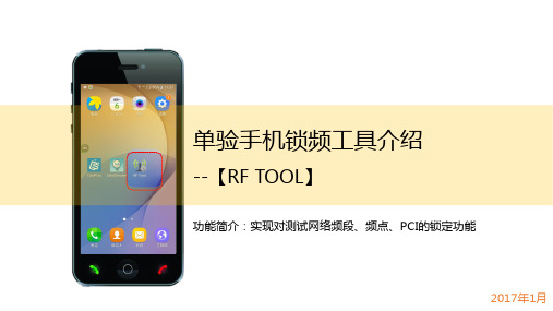
单验手机锁频工具介绍--【RF TOOL】功能简介:实现对测试网络频段、频点、PCI 的锁定功能2017年1月提纲1| 锁定频段功能2 | 锁定频点PCI功能3选择SIM 卡到达操作界面2选择[频段]功能启动RF Tool1到达目标频段5选择网络制式选择[5]Clear ……46选择目标频段9点击[7]Apply (8)点击“Back ”点击“更多”7☐锁频操作完成后手机即时生效,无需重启手机☐注意点:锁频点功能最终需要Apply 才生效完成2选择[7]Apply……选择[6]Select……1☐解锁操作完成后手机即时生效,无需重启手机解锁频段操作介绍☐注意点:锁频点功能最终需要Apply 才生效完成提纲1 | 锁定频段功能2 | 锁定频点PCI功能2点击[频点]功能启动软件1锁频点PCI 操作介绍(1)3选择SIM 卡到达锁频界面5选择频段范围6选择频段到达频点输入界面4锁频点PCI操作介绍(2)选择锁定网络制式7点击“更多”8点击”Key Input”9输入频点频点锁定,待重启锁频点PCI操作介绍(3)10点击”Back”11选择[6]Set PCI lock到达PCI输入界面12选择[Key Input]锁频点PCI操作介绍(4)13输入PCI 数值14锁定PCI ,待重启15选择”END ”16选择[重启手机]锁频点PCI操作介绍(5)完成锁频点PCI的操作需要手机重启后生效解锁频点PCI1选择[频点]功能2选择SIM卡3选择[7]RESET解锁成功重启手机后生效解锁频点PCI的操作需要手机重启后生效附录查看所频段、频段、PCI的方式方法1:使用RF Tool 自带的网络信息21选择网络信息功能3方法2:使用CDSplus的网络信息Thanks。
海思终端芯片ATE技术手册
本文参照业界通用做法,泄义了海思终端芯片类COT的推荐ATE测试策略,以及此类芯片在测试程序开发及量产时各版本的的测试规范及测试项目要求。
因技术和芯片规格持续发展,各IP的测试规范不断添加和完善。
对于成熟IP,程序开发时需要遵守该规范,新IP 测试规范建立时可参考对应的测试规范。
二、文档目的:支撑终端芯片媒体类产品达成<2000 FDPPM的质量目标。
三、使用规范:1)本文档针对IP的测试项仅进行简单说明,详细说明及指导手册请严格遵守《IP测试规范》及《IP测试CBB》02)芯片测试策略必须不松于该规范,如有测试条件的删减,需经过PDT经理/项目经理/PE/PL的联合会签,如有特殊需求,可酌情增加测试条件。
3.1程序版本说明FT/CP泄义常温测试(若只有此一道testflow,也泄义为FTA;若因向量深度或其他问题导致flow增加的,记为FTB,FTC…・)。
3.2 ATE量产测试流程>芯片应用特点芯片用于机顶盒,视频监控,数字电视等产品系列,质量及可靠性要求髙:发货量大, 成本敏感;工作环境为各国正常生活环境。
>测试流程> 补充说明⑴CP测试:低覆盖率(开始为中覆盖,后续根据量产数据进行删减测试项以达到降成本目的),DVS, VDDN,常温测试,1~4 site⑵FT测试:全覆盖,VDDN+VDDH+VDDL,常温测试(髙温待验证必要性),GB (根据CHAR结果),2~ 8siteso⑶量产SLT:可选项,长期可根据ATE覆盖率更新情况进行抽检或取消。
⑷可靠性测试:建议By wafer lot 进行HTOL/uHAST 抽检3.3测试项目标准ATE向量规格要求如下:aATE向量规格要求(CP_FT).xlsx3.4降成本策略当量产程序稳圧后,即可开始量产测试降成本工作,降成本细肖请参考《海思COT芯片ATE 测试降成本规范》,本文仅针对无线终端芯片进行策略性指导。
> 启动条件(需同时满足条件1和2,或满足条件3,投入产出比要合算):1、发货总量超过XX K,且最新测试程序版本连续XX lot测试良率波动<X sigma2、FDPPM连续XX月维持低水准(vXXX PPM)3、或基于供应策略,ATE主动发起降成本工作 > 降成本策略:整体策略:RTP前期以快速质量达标为优先,逐步进行测试降成本。
CXT4.1和MF832s锁频锁PCI指导书
由于现在市区的站点开通数已经到达一定规模,用户数量也逐渐增多,所以以前在市区闭小区测试的方法已经会影响用户感知度,这样容易被投诉。
所以现行的方法是进行锁PCI测试测试软件和设备清单:
CXT4.1 前台软件狗中兴MF832S GPS
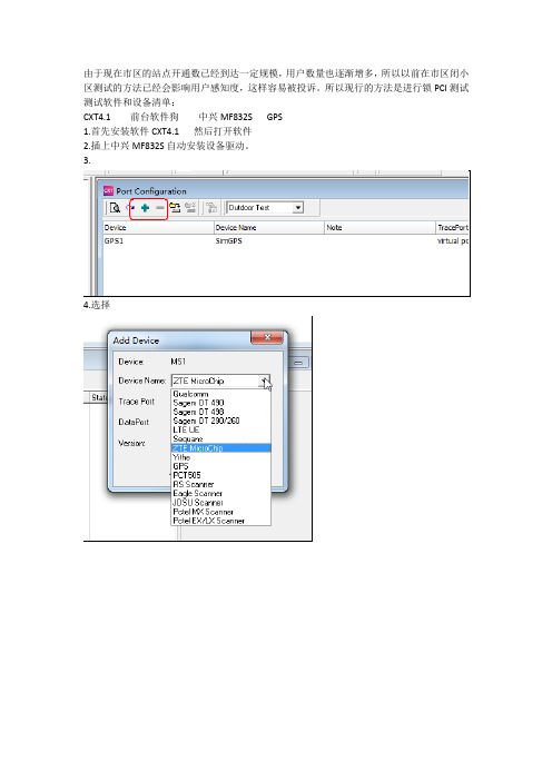
1.首先安装软件CXT4.1 然后打开软件
2.插上中兴MF832S自动安装设备驱动。
3.
4.选择
5.点击连接
6.点击
进入锁频程序
7.点击lock PCI
8.输入频点和PCI
注意宏站的频点是38350 室分的频点是38950 输入频点和PCI
点击SEND
显示这个则锁pci成功
如果要查询锁的是哪个小区则可以点击
将AT Command 里面的=0 改成?,其他的不要动,然后点击send
上图显示的是已经锁频点38350 ,PCI是146的小区
注意锁PCI以后点击send 大约5秒后把832S拔掉,然后重新插上此步骤不能省略9.这个时候打开终端的客户端
点击连接
这个时候就锁小区成功了。
这个时候占用的就是宏站的频点38350PCI是146的小区10.解除锁小区
1.点击断开
把客户端退掉
然后到CXT4.1 AT Command 点unlock frequency,显示ok 则成功
如果不放心的话,可以查询下,方法同上面讲的
注意:然后把终端拔掉然后插上。
此步骤不能省略
作者:卢涛涛。
门禁射频卡系列产品用户手册(SC700)V1.1_20140221

门禁产品射频卡系列用户手册(专业版)
版本:1.1 日期:2014 年 2 月 适用型号:SC700 或其他
内容介绍 本文档主要介绍了门禁射频卡系列产品的界面及菜单的功能操作,可与 Access3.5 软件配套使用。关 于产品的安装请参见相应产品的安装指南。
Hale Waihona Puke 重要申明重要申明首先感谢您选择本产品!在使用前,请您仔细阅读本产品的说明书。以避免设备受到不必要的损害! 本公司提醒您正确使用,将得到良好的使用效果和验证速度。 非经本公司书面同意,任何单位和个人不得擅自摘抄、复制本手册内容的部分或全部,并不得以任何 形式传播。 本手册中描述的产品中,可能包含我司及其可能存在的许可人享有版权的软件,除非获得相关权利人 的许可,否则,任何人不能以任何形式对前述软件进行复制、分发、修改、摘录、反编译、反汇编、解密、 反向工程、出租、转让、分许可以及其他侵权软件版权的行为,但是适用法禁止此类限制的除外。本公司 保留最终解释权及更改权。
Schlage AD-300 网络硬线锁用户指南说明书
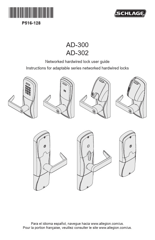
*P516-128*P516-128AD-300AD-302Networked hardwired lock user guideInstructions for adaptable series networked hardwired locksPara el idioma español, navegue hacia /us.Pour la portion française, veuillez consulter le site /us.Overview (3)Getting started (4)Schlage Utility Software (SUS) (5)Optional inside push button (IPB) (5)User management (5)Construction access mode (6)Locks with keypads – Construction access mode (6)Locks with card readers – Create a master construction credential (6)Locks with card readers – Add construction access mode user credentials (7)Cancel construction access mode (7)Lock address setup (8)Manually set the RS485 address (8)Set the RS485 address with Schlage utility software (SUS) (8)Connect to an access control panel (9)Cable/wire specifications (9)Test lock operation (11)Mechanical test (11)Electronic test (11)Reset to factory default settings (12)Level 1 factory default reset (12)Level 2 factory default reset (12)Communication properties (13)Communication failure (13)Power failure (13)Power Failure Modes (13)LED and beep reference (14)Schlage button LED (14)Troubleshooting (15)FCC/IC statements (16)This product is compliant of UL294 and ULC S319 standard. This product’s compliance would be invalidated through the use of any add-on, expansion, memory or other module that has not yet been evaluated for compatibility for use with this UL Listed product, in accordance with the requirements of the Standards UL294 and ULC S319. This product has been evaluated for CAN/ULC-S319 Class 1. UL294 Access Control Levels tested to: Destructive Attack - Level 1; Line Security - Level 1; Endurance - Level 4; Standby Power - Level 1.2 • Schlage • AD-300 user guide3 • Schlage • AD-300 user guideThe Schlage AD-300/AD-302 is an open architecture product designed to interface with access control panels (ACPs) which use the RSI RS485 protocol.When using an access control panel that does not use the RSI RS485 protocol, the addition of a Schlage PIB300 is required to provide a Wiegand or clock & data communications protocol.The Schlage AD-302 is a FIPS-201-2 certified product.• Powered by external power using a UL294 or ULC S318/ULC S319 listed powersupply capable of sourcing at least 250 mA @ 12 or 24 VDC.• The outside lever is normally locked.• The inside lever always allows egress.• The AD-300/AD-302 normally operates in networked mode. Information containedin the user credential is passed to an ACP , which controls lock functions. The ACP maintains the audit trail.AD-300/AD-302-CY AD-300/AD-302-MSAD-300/AD-302-MD AD-300/AD-302-993OutsideLeverInside LeverKeypadMulti-Tech ReaderMag Card Reader (insert)Mag Card Reader (swipe)Additional AD-300 Reader options: Mag + Keypad, Multi-Tech + Keypad.Note: Proximity card (PR, PRK) ONLY and Smart card (SM, SMK) ONLY readers have been discontinued and replaced by the Multi-Tech (MT, MTK) readers that provide all the same functionality as the original Proximity and Smart card readers in a single credential reader.The AD-302 reader is a FIPS-201-2 certified Multi-Tech + Keypad (FM2) reader.Follow these steps to set up a new lock.1. Install the lock. See the installation guide that came with the lock, or visit/us for more information.2. Make sure the power supply is properly connected. See Connect to an access controlpanel on page 9 for more information.3. Configure the Master Construction Credential (where applicable). See Constructionaccess mode on page 6 for more information. The lock should remain in construction access mode until you are ready to set up the rest of the system.4. Test the lock for proper mechanical and electronic operation. See Test lock operation onpage 11 for more information.5. Connect the lock to the Access Control Panel (ACP). See Connect to an access controlpanel on page 9 for more information.6. Consult the SUS user guide for information about configuration of the lock.7. Familiarize yourself with the information contained in this user guide.Save this user guide for future reference.4 • Schlage • AD-300 user guideThe SUS is used to configure locks and the PIB300, and to set the RS485 address.The SUS is used for programming lock characteristics and setup only. Access rights for the AD-300/AD-302 are set by the access control panel, not by the SUS.For more information about the SUS, see AD-Series Locks in the SUS user guide.The IPB state is communicated to the control panel through the RS485 connection. The manner in which the network access control software utilizes this communication is configured at the host. The IPB may be used to communicate a lock/unlock request or be completely ignored by the network software. Activity may only be reported to control systems connected by a RS485 connection.User management is controlled by the access control system. If the access control panel has not yet been connected, use construction access mode to add and delete users.L See Construction access mode on page 6 for more information.5 • Schlage • AD-300 user guideConstruction access mode is used to allow access before the lock has been programmed, and for testing purposes.• Enabled by default.• The lock will remain in construction access mode until the mode is cancelled as described below.• No audits are captured while lock is in construction access mode.• Use the same master construction credential for all the locks in the facility.• If you present the first card to a new lock to create the master construction credential and the card is not accepted, the lock has either been programmed or already has a master construction credential.• If the master construction credential cannot be located, or to put the lock back into construction access mode, reset the lock to factory settings (see page 12 for details). Locks with keypads – Construction access modeIn the factory default state, locks with keypads have a default PIN of 13579 and “#”, which can be used for installation, testing and construction access. T o test, enter default PIN. The Schlage button will blink and the lock will unlock.The default PIN, 13579 and “#” is automatically deleted when a construction access user credential is added to the lock, or a new programming credential is created, or the lock is programmed with the SUS.Locks with card readers – Create a master construction credentialThe master construction credential is used to program construction access mode credentials. To create a master construction credential:1. Press and hold the Schlage button while presenting a credential.2. The Schlage button will blink green on the left and right as confirmation.3. Use this card to add construction access mode user credentials.L The master construction credential will not grant access. It is used only to add additional credentials.6 • Schlage • AD-300 user guideLocks with card readers – Add construction access mode user credentialsCancel construction access modeDo one of the following:• Program the lock with the SUS. See the SUS user guide for more information.• Reset the lock to factory settings. See Reset to factory default settings on page 12 for more information.When construction mode is cancelled, the master construction credential and all other credentials added using the master construction credential will no longer function.7 • Schlage • AD-300 user guideManually set the RS485 addressL The lock MUST NOT be connected to RS485 communication during this procedure.1. Make sure that 12 or 24 VDC power is connected properly, and RS485 is not connected. L The Schlage button will blink red to indicate no communication with the access control panel.2. Open the door.3. Create a request-to-exit condition by holding down the inside lever or crash bar.Continue to hold the inside lever or crash bar through step 5.L If using a crash bar, Request to Exit (RTX) must be installed. If RTX is not installed, temporarily short the RTX input on the lock main PCB during thisprocedure.4. Press and release the Schlage button on the lock. Wait for the Schlage button to flashgreen.The lock address is now set to zero (0).5. Repeat step 4 until the number of times you have pressed the Schlage buttoncorresponds with the desired RS485 address.L Two (2) total presses sets the address to one, three (3) total presses sets the address to two, etc.L Manual RS485 addresses may be assigned up to address “15” (16 total presses).1 To assign addresses 16 - 255, use the SUS (lock properties, edit menu). Forfurther information, refer to the SUS user guide.6. Release the inside lever or crash bar. The Schlage button will blink green, and thebeeper will beep to indicate confirmation.L The number of green blinks and beeps indicates the RS485 address.7. After the confirmation blinks and beeps are completed, the Schlage button will againblink red to indicate no communication with the access control panel.Set the RS485 address with Schlage utility software (SUS)The RS485 address may be set using the SUS. Please refer to the Schlage utility software user guide for details.1 Check your ACP to determine how the address assignments run. Most access control systems run 1 - 16,however some systems run 0 - 15 (true RS485).8 • Schlage • AD-300 user guide• For compliance with UL 294, product must be used with a UL 294 Listed access controlpanel or unit. For compliance with CAN/ULC -S319, product must be used with a CAN/ULC -S319 Listed access control panel or unit.• The power supply may be connected to either: a) Auxiliary Power Inputs on the mainboard or, b) VIN (PWR) and GND connectors on the RS485 communication board. L The EIA RS485 Specification labels the data wires as “A” and “B” but manyRS485 products label their wires “+” and “-.” Some products associate the “+” signal with “A”, some with “B”. The bottom line is that the “+” should always be connected to the “+” and the “-” to the “-” , however it is designated. Reversing the polarity will not damage either RS485 device, it will only fail to communicate. Attempt to connect “+” to “+” and “-” to “-” . If it does not work, switch them.WARNING: DO NOT attach power to A/B data terminals!Cable/wire specifications2 Wire4 Wire10 • Schlage • AD-300 user guideIf you encounter problems while performing any of the following tests, review the installation guide and correct any problems.Mechanical test1. Rotate the inside lever. Operation should be smooth and the latch should retract.2. Insert the key into the keyway and rotate the key or the key and lever to open the door.Operation should be smooth, and the latch should retract.Electronic testTest the AD-300/AD-302 in factory default mode1. Press any number key. The lock should beep.2. Press the Schlage button. The keypad should light blue for a few seconds.3. Enter the default PIN (13579 and “#”). The lock should unlock momentarily and relockafter the default relock delay (3 seconds).4. Present a credential to the reader. The lock will beep and the Schlage button will blinkred one time. When the lock is in factory default mode and RS485 is not connected, no credentials are accepted.Test the AD-300/AD-302 in construction access mode1. When the master construction credential is presented, the lock will beep and theSchlage button will light green for 20 seconds awaiting the presentation of anothercredential to be granted construction user access.2. When a valid construction access user credential is presented, the lock will unlock for there-latch delay period (default three seconds), and the Schlage button will blink green.When the lock re-locks after the re-latch delay period, the Schlage button will blink red.3. If an invalid construction access user credential is presented, the lock will beep and theSchlage button will blink red one time. See Construction access mode on page 6 for more information.NOTE: Construction access mode is cancelled when the lock is reset to factory defaults. When construction access mode is cancelled, the master construction credential and all other credentials added using the master construction credential will no longer function.Test with the AD-300/AD-302 linked to an access control panel1. Present a valid credential to the lock. The Schlage button will blink green, a beep willsound and the door will unlock for the preset lock delay period. The lock will re-lock after the lock delay period and the Schlage button will then blink red.2. If an invalid credential is presented, the Schlage button will blink red, a beep will soundand the door will not unlock. Credential data for all credentials is reported to the ACP.11 • Schlage • AD-300 user guideAll information in the lock will be deleted and reset to factory defaults!Level 1 factory default resetL Level 1 factory default reset will delete configurations and settings in the main controller in the lock. Lock settings that will be deleted include functions, failure mode, and re-lock delays.L Level 1 factory default reset will not reset configurations and settings in the reader.1. Remove the top inside cover.2. Press and hold the Schlage button until two (2) beeps sound (10 seconds).3. Release the Schlage button.4. Press and release the inside push button (IPB) three (3) times within 10 seconds. Onebeep will sound and one red blink will occur with each press.5. The Schlage button and IPB will both light green for one second and a one-second beepwill sound to confirm that the lock has been reset.L If IPB is not pressed 3 times within 10 seconds, two beeps with two red blinks indicate timeout.6. Replace the top inside cover.Level 2 factory default resetL Level 2 factory default reset will delete all configurations and settings in the lock and the reader.L Reader configurations that will reset to factory default include: credential format, magstripe reader track and beeper default.L Days in use counter and lock type configurations will not reset.To complete Level 2 factory default reset, repeat steps 2 through 5 above within 10 seconds of the confirmation signals of Level 1 factory default reset. If more than 10 seconds pass after the confirmation signals of Level 1 reset, then Level 1 reset will be repeated.12 • Schlage • AD-300 user guideIf communication fails between the AD-300/AD-302 and the ACP, the lock will go into communication failure mode. If the ACP loses power, the lock can lock, unlock, remain as-is, or allow valid access without communication to the ACP. This mode can be configured using the SUS. See the SUS User Guide for more information.Cache mode is not applicable on AD-302 locks.Network mode When the lock is communicating with the ACP, information contained in the user credential is passed to the ACP, which controls lock functions. The ACP should maintain the audit trail.Cache mode Applicable only to AD-300. Upon communication failure, access may be enabled for facility codes or recent valid users. See the SUS user guide for details on the configuration of this setting.If communication fails between the AD-300/AD-302 and the ACP or the PIB300, the lock will go into communication failure mode. This mode can be configured using the SUS. See theSUS user guide for more information.In addition, the AD-300 has an internal cache that can be enabled using the SUS to allow limited access while the lock is offline. If cache mode is enabled, it is not affected by the communication failure mode configuration. See the SUS user guide for more information.Power failureL Power failure does not affect any programmed data. Use the SUS to configure power failure mode. The default power failure mode is “as-Is”.When power failure is detected, the lock will instantly switch to the configured mode. Credentials will no longer allow access.• If the power failure mode is “fail secure locked”, then the mechanical override key must be used to gain access (when equipped).• If the power failure mode is “fail secure locked” or “fail unsecure unlocked”, the AD-300 will recharge for two (2) minutes after power is restored. During this two-minuterecharge, the AD-300 will remain in power failure mode and the Schlage button will blink alternating green on the left and red on the right.Power Failure Modes13 • Schlage • AD-300 user guideMost LED and beep indicators are configured using the SUS. See the SUS user guide for more information.Schlage button LEDL Note: The access control panel may have some control over the Schlage button lights, and the actual response may vary.14 • Schlage • AD-300 user guide15 • Schlage • AD-300 user guide© Allegion 2018Printed in U.S.A.P516-128 Rev. 06/18-mAllegion Agency statementsCompliance StatementThis device complies with Part 15 of the FCC Rules.Operation is subject to the following two conditions:1. This device may not cause harmful interference, and2. This device must accept any interference received, including interference that may cause undesired operation.WarningChanges or modifications not expressly approved by the party responsible for compliance could void the user’s authority to operate the equipment.FCC interference statementThis equipment has been tested and found to comply with the limits for a Class B digital device, pursuant to Part 15 of the FCC Rules. These limits are designed to provide reasonable protection against harmful interference in a residential installation. This equipment generates uses and can radiate radio frequency energy and, if not installed and used in accordance with the instructions, may cause harmful interference to radio communications. However, there is no guarantee that interference will not occur in a particular installation. If this equipment does cause harmful interference to radio or television reception, which can be determined by turning the equipment off and on, the user is encouraged to try to correct the interference by one of the following measures:• Reorient or relocate the receiving antenna.• Increase the separation between the equipment and receiver.• Connect the equipment into an outlet on a circuit different from that to which the receiver is connected.Consult the dealer or an experienced radio/TV technician for help.Industry Canada statementsThis equipment has been tested and found to comply to Industry Canada ICES-003.CAN ICES-3(B)/NMB-3(B)。
海思q-time管控标准
海思q-time管控标准下载温馨提示:该文档是我店铺精心编制而成,希望大家下载以后,能够帮助大家解决实际的问题。
文档下载后可定制随意修改,请根据实际需要进行相应的调整和使用,谢谢!并且,本店铺为大家提供各种各样类型的实用资料,如教育随笔、日记赏析、句子摘抄、古诗大全、经典美文、话题作文、工作总结、词语解析、文案摘录、其他资料等等,如想了解不同资料格式和写法,敬请关注!Download tips: This document is carefully compiled by the editor. I hope that after you download them, they can help yousolve practical problems. The document can be customized and modified after downloading, please adjust and use it according to actual needs, thank you!In addition, our shop provides you with various types of practical materials, such as educational essays, diary appreciation, sentence excerpts, ancient poems, classic articles, topic composition, work summary, word parsing, copy excerpts,other materials and so on, want to know different data formats and writing methods, please pay attention!随着科技的飞速发展,人们的生活节奏越来越快,工作压力也在不断增加。
基站锁频
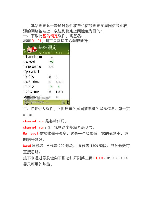
基站锁定是一款通过软件将手机信号锁定在周围信号比较强的网络基站上,以达到稳定上网速度为目的!一、下载此基站锁定软件,需签名。
界面01.01;翻页只需按下方向键就行!二、打开进入软件,上图显示的是当前手机的屏显信息。
第一页01.01:channel mum是基站代码,channel mum:3,说明这个基站号是3号。
Rx level是接收信号强度,这是一个负数值,它的值越小,说明信号越好。
band是频段,9代表900频段,18代表1800频段。
其他参数可直接忽略。
接下来通过导航键向下搬动打开到第三页01.03。
01.03-01.05显示可用的基站。
CH是基站代码,RX是信号强度第四到第五页也是显示周围基站信息,锁定基站前可以用笔先记下你想锁定的基站代码。
三、接下来直接打开到基站锁定页面,选项——更改显示器(C hange display)——输入0112并确认。
则跳到了第十二页01.在第十二页01.12:你可以看到最后一行BTS TEST:OFF,按左键打开菜单——选基站锁定(EXECUTE)——输入你想要锁定的基站代码532——确定就OK了。
你会发现已锁定了BTS TE ST:532锁定基站后翻到第三页,你会发现看不到周围基站了,所以你要测试哪个基站网络好就先把基站代码全部抄下来慢慢测试,一定有几个是能让你满意的!相关问题答疑:基站锁定不适合在移动状态下使用,因为每一个基站的信号覆盖范围都是有限的,你一旦离开这个覆盖范围就会失去信号了,这时只能通过重启一下手机或解除锁定状态即可。
如果不用了,或者要做长距离的移动时。
怎么解锁呢?解锁基站其实很简单,只要将手机重启一下或者:选项——基站锁定(此时基站锁定下会出现一个0)不输入任何数字直接选——确定(后会出现ERR无信号状态)——再选基站锁定——输入125——确定——稍等片刻不到20秒——马上出现基站锁定前的信号,退到页面01.01,可发现可用的基站!用FTD基站锁定,锁定edge基站,在锁定的瞬间手机重启了,重启后怎么弄也没有信号,再重启也是没有,调到125也是没有,删除了这个软件还是没有信!解决方法:选项——Change display——输入0113并确认跳到0113这一页——再选项——Execut确认一下,此时屏幕下方最后一行会出现ACCEPTED(呼叫接受)、REVERSE(相反)、DISCARD(屏蔽)中的任意一个,要选择ACCEPTED就行了。
- 1、下载文档前请自行甄别文档内容的完整性,平台不提供额外的编辑、内容补充、找答案等附加服务。
- 2、"仅部分预览"的文档,不可在线预览部分如存在完整性等问题,可反馈申请退款(可完整预览的文档不适用该条件!)。
- 3、如文档侵犯您的权益,请联系客服反馈,我们会尽快为您处理(人工客服工作时间:9:00-18:30)。
海思终端锁频指导书
Huawei Technologies Co., Ltd.
华为技术有限公司
All rights reserved
版权所有侵权必究
(仅供内部使用)
1终端端口调试
1.1 终端端口识别
终端在出厂时只开放了PC UI Interface端口,此时终端无法进行锁频操作
1.2 IPOP 工具使用指导
IPOP 是一个简易工具,直接打开即可使用。
打开IPOP 如下所示:
点击“终端工具”,出现如下所示界面:
点击上图中的“新建连接”,出现如下所示界面,选择设备管理器中的PC UI COM 口,然后对其命名,最后点击确定,如下所示:
✓出现如下所示界面:
✓点解“右上角的红色大写T 字”,出现如下所示界面:
✓在上述所画框图中输入所需的AT 命令,并点击“开始发送”:
注:AT 命令:
AT^OPWORD=GL04P2012
AT^SETPORT="A1,A2;14,13,12,A,3,16,5,A1,A2"
at^tmode=3
当AT 命令发送之后,在截图中的上半个蓝色屏幕中出现OK 之后,则说明命令发送成功。
✓在命令发送成功之后,终端会进行自动重启,此时需要稍微等待下,同时打开设备管理器查看端口显示情况,终端会自动进行端口识别及程序安装过程,此时只需要
耐心等待即可,当终端完全重启完毕且端口正确识别之后,显示如下所示:
只有当上述端口全部识别出来之后即可和Histudio 进行连接。
2锁频操作
2.1 NV项修改
选中“ID”项中的0xd232[NV_ID_RRC_LOCK_FREQ_SWITCH],修改锁频参数
参数分十进制和十六进制两种展现形式,如果显示十六进制,则在空白处右键,将下图的Hex Display勾掉即可。
修改项共四项:
enLockInd:0-不锁频、1-锁频段、2-锁频率(指中心频率)、3-锁小区
ucBandInd:频段,中国电信FDD频段为Band1,输入1即可;TDD频段为band41 usCellId:物理小区ID,PCI;如果选择2-锁频率的方式,则该项可以不填,保持0默认即可usFreqPoint(不能根据字面意思理解为频点):待锁定的中心频率* 10;例如:下行频点500,则对应的中心频率为2160MHz,那么此处输入为21600。
修改完成后,右键选择“Write”,将NV项写入终端3备注
该方法已在E3276、E5375终端上验证成功。
