爱国者R5530说明书
aigo无线硬盘客户端软件使用说明V

爱国者无线硬盘 客户端软件使用说明V3.1目录免责声明 (3)特别提示: (4)一、设备的准备与连接 (4)1.1开机 (4)1.2 WiFi信号的连接 (4)1.2.1 Windows 平台 (4)1.2.2 iOS 平台 (5)1.2.3 Android 平台 (8)1.3移动网络存储服务器(移动NAS)模式 (12)二、客户端软件的安装 (13)2.1 Windows 平台 (13)2.2 iOS 平台 (14)2.3 Android 平台 (14)三、Windows客户端软件的界面说明 (17)四、iOS、Android客户端软件的界面说明 (18)4.1登录设备 (18)4.2 DLNA目录 (20)4.3文件播放 (22)4.3.1视频播放 (22)4.3.2音乐播放 (23)4.3.3图片浏览 (24)4.3.4文档浏览 (24)4.3.5 DLNA推送 (25)4.3.6 AirPlay功能 (26)4.4文件管理 (27)4.4.1分享按钮 (29)4.4.2操作按钮 (30)4.4.3传输按钮 (33)4.5设置界面 (35)4.5.1设备设置 (36)4.5.1.1无线设置 (36)4.5.1.2局域网设置 (38)4.5.1.3互联网设置 (39)4.5.1.4系统设置 (43)4.5.2来宾用户 (45)4.5.3缓存设置 (46)4.5.4语言设置 (46)4.5.5关于 (47)4.5.6注销 (47)五、使用第三方软件进行访问 (48)由于产品的更新,本手册中的图片和文字可能与您的设备中显示的图文略有不同,某些细微的变更将不会影响您的操作,请以实物操作为主。
一、感谢您购买爱国者无线硬盘产品。
在使用本产品之前,请认真阅读快速使用说明和本说明书。
当您开始使用爱国者无线硬盘产品时,爱国者电子认为您已经认真阅读了本说明书。
二、本产品为移动存储产品,用于用户数据的冗余备份,请用户在使用过程中及时对其中的数据进行备份。
MSCR500说明书
DB9 引脚定义
脚号 2 3 5 7 8
1,4,6,9
定义 接收数据 RD 发送数据 TD 信号地 GND 请求发送 RTS 允许发送 CTS/接收时钟 CLK 空脚 NC
方向 MODEM—→主机 MODEM←―主机
公共端 MODEM←—主机 MODEM—→主机
—
3、功能设置
打开机箱盖板,通过 MODEM 板上的跳线器组 S1 可以设置或修改功能、参数,具体方法下面 逐一加以说明。
2、面板显示说明
MSCR501 调制解调器的工作状态由面板上的 LED 指示灯反映,它们的状态定义见下表。
符号 CD TD RD RUN CTS
颜色 红 绿 绿 绿 绿
状态 亮 闪 闪 闪 亮
定
义
接收信号中断或电平低于门限值,告警
正在接收数据终端的数据
正在向数据终端发送数据
正常运行
关闭载频信号此灯灭
如果用 M 表示码元的调制电平数,那么信息传输速率 R 为 R=Nb ㏒ 2 M (比特---bit/s)
3
MSCR501 调制解调器
我们知道,四元(也就是四进制)码的码元是 4,这时假设码元符号的传输速率是 600Bd,则
R=1200bit/s。
但是,在发送的数据只有“0”、“1”两种状态(也就是二值逻辑)的情况下,码元符号的传输
· 循环式/问答式自适应 由于采用四线传输方式,对于循环式和问答式的数据信息是自动适应的,无需预置。
3、技术参数
传输速率 发信电平 收信电平
300/600/1200bit/s 可选 0~-18dB 分档选用 0~-40dB 自动适应
1
MSCR501 调制解调器
音频接口 数据接口 告警门限 误码率 供电电源
Riverdi 3.5英寸 TFT 显示屏参考手册说明书

ITEMCONTENTSUNITLCD Type TFT/Transmissive/Normally white / Size3.5Inch Viewing Direction12:00 (without image inversion) O’ Clock Gray Scale Inversion Direction 6:00O’ Clock Number of Dots 320 x (RGB) × 240 / Driver ICBT81x / Interface TypeSPI/QSPI/ Module Memory Size 1 MB (BT81x) + 64 Mb (external flash) / Color Depth16.7M/ Pixel Arrangement RGB Vertical Stripe/ Surface Treatment Anti-glare / Clear (for CTP) / Input Voltage3.3V3.5” EVE3 SERIES LCD TFTRiTFT-35 seriesRev.1.0 2018-10-22L C D T F T M o d u l e S p e c i f i c a t i o nNote 1: RoHS, REACH SVHC compliant Note 2: LCM weight tolerance: ± 5%.CONTENTS (2)1 MODULE CLASSIFICATION INFORMATION (3)2 ASSEMBLY GUIDE - INTEGRATION (3)2.1 Mounting frame (4)3 MODULE DRAWING (4)4 ABSOLUTE MAXIMUM RATINGS (5)5 ELECTRICAL CHARACTERISTICS (5)6 BACKLIGHT CHARACTERISTICS (5)7 ELECTRO-OPTICAL CHARACTERISTICS (5)8 INTERFACE DESCRIPTION (7)9 BT8x CONTROLLER SPECIFICATIONS (8)9.1 Serial host interface (8)9.2 Block Diagram (8)9.3 Host interface SPI mode 0 (9)9.4 Backlight driver block diagram (9)10 LCD TIMING CHARACTERISTICS (9)10.1 Clock and data input time diagram (9)10.2 Parallel RGB timing table (11)11 TOUCH SCREEN PANEL SPECIFICATIONS (11)11.1 Electrical characteristics (11)11.1.1 For capacitive touch panel (11)11.1.2 For resistive touch panel (12)11.2 Mechanical characteristics (12)11.2.1 For capacitive touch panel (12)11.2.2 For resistive touch panel (13)12 INSPECTION (13)12.1 Inspection condition (13)12.2 Inspection standard (14)13 RELIABILITY TEST (17)14 LEGAL INFORMATION (18)1. BRAND RV – Riverdi2. PRODUCT TYPE T – TFT StandardF – TFT Custom3. DISPLAY SIZE 35– 3.5”4. MODEL SERIAL NO. A (A-Z)5. RESOLUTION H– 320x240 px6. INTERFACE B – TFT + Controller BT81x7. FRAME N – No FrameF – Mounting Frame8. BACKLIGHT TYPE W – LED White9. TOUCH PANEL N – No Touch PanelR – Resistive Touch Panel C – Capacitive Touch Panel10. VERSION 00(00-99)RiTFT-35-RES RVT35AHBNWR00 BT816, resistive touch panelRiTFT-35-CAP RVT35AHBNWC00 BT815, capacitive touch panelRiTFT-35-FR RVT35AHBFWN00 BT816, no touch panel, mounting frame RiTFT-35-RES-FR RVT35AHBFWR00 BT816, resistive touch panel, mounting frame RiTFT-35-CAP-FR RVT35AHBFWC00 BT815, capacitive touch panel, mounting frame2.1Mounting frameFor dimension s 3.5”, 4.3”, 5.0” and 7.0” the product with mounting frame version is available. Thanks to the four catches attached to the side, frame provides strong assembly to the surface by mounting element (like the screw, see Figure 3). The frames are specially designed to fit Riverdi products perfectly. The diameter of the mounting hole is 3.5mm.Figure 1. Mounting frameRiTFT-35 series3MODULE DRAWING `` RiTFT-35© 2018 Riverdi Page 4 of 24 RiTFT-35 seriesRiTFT-35-FR© 2018 Riverdi Page 5 of 24 RiTFT-35 seriesRiTFT-35-CAP© 2018 Riverdi Page 6 of 24 RiTFT-35-CAP-FR© 2018 Riverdi Page 7 of 24 RiTFT-35-RES© 2018 Riverdi Page 8 of 24 RiTFT-35-RES-FR© 2018 Riverdi Page 9 of 24 4ABSOLUTE MAXIMUM RATINGSPARAMETER SYMBOL MIN MAX UNITSupply Voltage for Logic VDD 0 4.0 V Supply Voltage for LED Inverter BLVDD 0 7.0 VInput Voltage for Logic VIN 0 4.0 VLED forward current (each LED) IF - 25 mA Operating Temperature T OP-20 70 °C PARAMETER SYMBOL MIN TYP MAX UNIT NOTES Supply Voltage For Module VDD 3.0 3.3 3.6 VInput Voltage for LED Inverter BLVDD 2.8 5.0 5.5 VLED Backlight Current IDD backlight- 150 187 mA BLVDD=3.3V LED Backlight Current IDD backlight- 93 117 mA BLVDD=5V Input Voltage ' H ' level V IH0.7VDD - VDD VInput Voltage ' L ' level V IL0 - 0.2VDD VInput Current I In TBD mAInput Current for module with CTP I InC TBD mAITEM SYMBOL MIN TYP MAX UNIT Voltage for LED backlight V l- 19.2 20.4 V Current for LED backlight I l- 20 25 mA LED Life Time - 30000 50000 - HrsLNote 1. Contrast Ratio(CR) is defined mathematically as below, for more information see Figure .Contrast Ratio =Average Surface Luminance with all white pixels (P1,P2,P3,P4,P5) Average Surface Luminance with all black pixels (P1,P2,P3,P4,P5)Note 2. Surface luminance is the LCD surface from the surface with all pixels displaying white. For more information, see Figure .Lv = Average Surface Luminance with all white pixels (P1, P2, P3, P4, P5)Note 3.The uniformity in surface luminance δ WHITE is determined by measuring luminance at each test position 1 through 5, and then dividing the maximum luminance of 5 points luminance by minimum luminance of 5 points luminance. For more information, see Figure .δ WHITE =Minimum Surface Luminance with all white pixels (P1,P2,P3,P4,P5) Maximum Surface Luminance with all white pixels (P1,P2,P3,P4,P5)Note 4. Response time is the time required for the display to transition from white to black (Rise Time, Tr) and from black to white (Decay Time, Tf). For additional information see FIG 1. The test equipment is Autronic-Melchers’s ConoScope series.Note 5.CIE (x, y) chromaticity, the x, y value is determined by measuring luminance at each test position 1 through 5, and then make average value.Note 6. Viewing angle is the angle at which the contrast ratio is greater than 2. For TFT module the contrast ratio is greater than 10. The angles are determined for the horizontal or x axis and the vertical or y axis with respect to the z axis which is normal to the LCD surface. For more information see Figure .Note 7. For viewing angle and response time testing, the testing data is based on Autronic-Melchers’s ConoScope series. Instruments for Contrast Ratio, Surface Luminance, Luminance Uniformity, CIE the test data is based on TOPCON’s BM-5 photo detector.Note 8. For TFT module, Gray scale reverse occurs in the direction of panel viewing angle.Figure 2. The definition of response timeFigure 3. Measuring method for Contrast ratio, surface luminance, Luminance uniformity, CIE (x, y) chromaticityFigure 4.The definition of viewing angle8INTERFACE DESCRIPTION9BT8x CONTROLLER SPECIFICATIONSBT8x or EVE3 (Embedded Video Engine 3) simplifies the system architecture for advanced human machine interfaces (HMIs) by providing functionality for display, audio, and touch as well as an object oriented architecture approach that extends from display creation to the rendering of the graphics.9.1Serial host interfaceFigure 5.SPI interface connection Figure 6. QSPI interface connectionSPI Interface– the SPI slave interface operates up to 30MHz.Only SPI mode 0 is supported. The SPI interface is selected by default (MODE pin is internally pulled low by 47k resistor).9.2Block DiagramFigure 7.. BT8x Block diagram9.3Host interface SPI mode 0Figure 8. SPI timing diagramFor more information about BT8x controller please go to official BT8x website.https:///Products/ICs/BT81X.html9.4Backlight driver block diagramBacklight enable signal is internally connected to BT8x Backlight control pin. This pin is controlled by two BT8x’s registers. One of them specifies the PWM output frequency, second one specifies the duty cycle. Refer to BT8x datasheet for more information.Figure 9. Backlight driver block diagram10LCD TIMING CHARACTERISTICS10.1Clock and data input time diagramFigure 10. DE mode timing diagramBT8xFigure 11. SYNC mode timing diagramFigure 12. Timing diagram10.2Parallel RGB timing tableTiming parameter (VDD=3.3V, GND=0V, Ta=25˚C)PARAMETER SYMBOL MIN TYP MAX UNIT CONDITION CLK Clock Time T clk 1/Max(F CLK) - 1/Min(F CLK) ns -11TOUCH SCREEN PANEL SPECIFICATIONS11.1Electrical characteristicsNote: Avoid operating with hard or sharp material such as a ball point pen or a mechanical pencil except a polyacetal pen (tip R0.8mm or less) or a fingerITEM VALUE UNIT REMARKMin. Typ. Max.Linearity - - 1.5 % Analog X and Y directions Terminal Resistance 200 - 900 ΩX100 - 600 ΩY11.2Mechanical characteristicsNote 1: Force test condition, Input DC 5V on X direction, Drop off Polyacetal Stylus (R0.8), until output voltage stabilize, then get the R8.0mm Silicon rubber and do finger Activation force test. Next step, 9 points.Note 2: Measurement surface area conditions, Scratch 100,000 times straight line on the film with a stylus change every 20,000 times with Force: 250gf, Speed: 60mm/sec by R0.8 polaceteal stylus.Note 3: Pitting test, Pit 1, 000, 000 times on the film with R0.8 silicon rubber with Force: 250gf and Speed: 2 times/sec.Note 1: Force test condition, Input DC 5V on X direction, drop off Polyacetal Stylus (R0.8), until output voltage stabilize, then get the R8.0mm Silicon rubber and do finger Activation force test. Next step, 9 points.ITEM VALUE UNIT REMARKMin. Typ. Max.12INSPECTIONStandard acceptance/rejection criteria for TFT module.12.1Inspection conditionAmbient conditions:•Temperature: 25±°C•Humidity: (60±10) %RH•Illumination: Single fluorescent lamp non-directive (300 to 700 lux)Viewing distance:35±5cm between inspector bare eye and LCD.Viewing Angle:U/D: 45°/45°, L/R 45°/45°12.2Inspection standard Item Criterion Black spots, whitespots, light leakage,Foreign Particle(round Type)D=(x+y)2*Spots density: 10 mmSize < 5”Average Diameter Qualified QtyD < 0.2 mm Ignored0.2 mm < D < 0.3 mm 30.3 mm < D < 0.5 mm 20.5 mm < D 0Size >= 5”Average Diameter Qualified Qty D<0.2 mm Ignored0.2 mm < D < 0.3 mm 40.3 mm < D < 0.5 mm 20.5 mm < D 0Clear spotsSize >= 5”Average Diameter Qualified Qty D<0.2 mmIgnored 0.2 mm < D < 0.3 mm 4 0.3 mm < D < 0.5 mm 2 0.5 mm < D*Spots density: 10 mm Size < 5”Average Diameter Qualified Qty D < 0.2 mmIgnored 0.2 mm < D < 0.3 mm 3 0.3 mm < D < 0.5 mm 2 0.5 mm < D 0Polarizer bubblesSize < 5”Average Diameter Qualified Qty D < 0.2 mmIgnored 0.2 mm < D < 0.5 mm 3 0.5 mm < D < 1 mm 2 1 mm < D 0 Total Q’ty 3Size >= 5”Average Diameter Qualified Qty D<0.25 mmIgnored 0.25 mm < D < 0.5 mm 3 0.5 mm < D 0Electrical Dot DefectSize < 5”itemQualified Qty Black do defect 4 Bright dot defect 2 Total Dot 5Size >= 5”itemQualified Qty Black do defect 5 Bright dot defect 2 Total Dot 5Touch panel spotSize < 5”Average Diameter Qualified QtyD < 0.2 mm Ignored0.2 mm < D < 0.4 mm 50.4 mm < D < 0.5 mm 213RELIABILITY TESTNO. TEST ITEM TEST CONDITION REMARKS1 High Temperature Storage 80±2°C/240hours Note 22 Low Temperature Storage -30±2°C/240hours Note 1,2Note 1: Without water condensation.Note 2:The function test shall be conducted after 2 hours storage at the room temperature and humidity after removed from the test chamber.14LEGAL INFORMATIONRiverdi makes no warranty, either expressed or implied with respect to any product, and specifically disclaims all other warranties, including, without limitation, warranties for merchantability, non-infringement and fitness for any particular purpose. Information about device are the property of Riverdi and may be the subject of patents pending or granted. It is not allowed to copy or disclosed this document without prior written permission.Riverdi endeavors to ensure that the all contained information in this document are correct but does not accept liability for any error or omission. Riverdi products are in developing process and published information may be not up to date. Riverdi reserves the right to update and makes changes to Specifications or written material without prior notice at any time. It is important to check the current position with Riverdi.Images and graphics used in this document are only for illustrative the purpose. All images and graphics are possible to be displayed on the range products of Riverdi, however the quality may vary. Riverdi is no liable to the buyer or to any third part for any indirect, incidental, special, consequential, punitive or exemplary damages (including without limitation lost profits, lost savings, or loss of business opportunity) relating to any product, service provided or to be provided by Riverdi, or the use or inability to use the same, even if Riverdi has been advised of the possibility of such damages.Riverdi products are not fault tolerant nor designed, manufactured or intended for use or resale as on line control equipment in hazardous environments requiring fail – safe performance, such as in the operation of nuclear facilities, aircraft navigation or communication systems, air traffic control, direct life support machines or weapons systems in which the failure of the product could lead directly to death, personal injury or severe physical or environmental damage (‘High Risk Activities’). Riverdi and its suppliers specifically disclaim any expressed or implied warranty of fitness for High Risk Activities. Using Riverdi products and devices in 'High Risk Activities' and in any other application is entirely at the buyer’s risk, and the buyer agrees to defend, indemnify and hold harmless Riverdi from any and all damages, claims or expenses resulting from such use. No licenses are conveyed, implicitly or otherwise, under any Riverdi intellectual property rights.。
4英寸重力增强彩色方形墙壁洒光 LED 模块 IS-R1058R3 安装指南说明书

IMPORTANT SAFETY INSTRUCTIONS■Read all installation instructions before installing. It is important to save these instructions.■Only install and connect LED module with power disconnected at the circuit breaker. Hot plugging, or connecting the module with power on, could damage the LEDs and is not covered by warranty.■Observe and follow all label information and instructions regarding dry, damp and wet location listings, proper Intense LED module, warnings of installation near combustible materials and/or insulation.■Turn off power at circuit breaker before attempting to install or perform maintenance on the fixtures. ■Be sure to connect ground wire to prevent electric shock or other potential hazards.■The product must be installed in a manner consistent with the intended use and in compliance with the national electrical codes and local codes by a person familiar with the construction and operation of the product and the hazards involved. ■Do not block the trim aperture as this may cause unsafe operating conditions.■WARNING: RISK OF FIRE. Non-IC fixture requires that insulation must be kept at least 3” away from all sides of the fixture. Minimum of 90°C supply conductors. Consult a qualified electrician before installation.WARNING: Use only Intense Lighting trims listed for use with this fixture. Use of trims other than those listed by Intense Lighting is a violation of N.E.C 110-3(B) and voids all warranties.Tunable White onlyFor 0-10V Continuous CCT Control. Connect a 0-10V control device to the blue (+) and white(ground) wires. When the fixture is powered up, the 0-10V control will adjust the CCT over the tunable range.Tunable White & Dynamic DimmingA 0-10V control may also be added for dimming(as shown). Adjustments to Dimming levels are a percentage of the 0-10V Dim setting (Trim). If a 0-10V control is not used for dimming, the gray (ground) andviolet (+) wires must be grounded together.Dimmer By Others Compatible Control SystemsBrand Model Leviton IP710-DLX Leviton IP710-LFZ Leviton Sapphire Leviton Omnitouch Lutron Diva, DVTV Lutron Nova-T, NTFTV Lutron Diva, NFTV Lutron Grafik Eye -GRX-TVI with GRX3503 Lutron Energi Savr Node - QSN-4T16-S Lutron TVM2 Module Lightolier V2000FAMU Lightolier ZP600FAM120 Lightolier MP1500FAM120 Watt Stopper DCLV1DMX Control Options1. Warm dim mode: In this mode, the luminaire warms as it dims. It uses only one DMX-channel.2. CCT tuning mode: In this mode, luminaire’s CCT tunes along the black body curve. It uses two DMX-channels, one for Brightness control and one for CCT tuningDMX RDM Dimming and Tuning Control FunctionsStandard default is Ch 1 dimming and Ch 2 CCT Control for Tunable White.Standard default is Ch 1 for Dynamic Warm DimmingCompatible Control SystemsBrand Model Acuity Fresco DMXister DMXister test suite NXP NXP RDM SDK Pathway Connect Pathport Open Lighting Project RDM test suiteWiring DiagramDALI Control FunctionsThe luminaire can be operating in two different modes:- Dynamic warm dimming mode, DALI device type 6 (DT6) compatible (Control gear 102)- CCT tuning mode, DALI device type 8 (DT8) compatible (Control gear: 209 Color control)By default the unit will start up in warm dimming mode with base address 0, but when it receives a DT8 command (dim warm/cool) it will switch to the CCT tuning mode. It cannot switch automatically back. Only a special DALI command (SetTcPHY_coolest=0) or resetting the ARD function will set it back to the warm dimming mode. This should not be done dynamically as there are only a limited amount of resets possible (10,000).DALI Dimming and Tuning Control FunctionsCompatible Control SystemsBrand ModelLeviton DALI Controller CD250-C Hadler DALI uPLunatoneDALI Switch 86459793Installation Instructions0-10V Dimming and Tuning Control FunctionsIS-R1058R34 of 4。
AC300说明书
目录1 引言 (4)1.1 编写目的 (4)1.2 注意事项 (4)2 启动 (4)3 初始界面 (4)4 应用程序结构与模块 (6)4.1 用户管理 (9)4.1.1 用户登记 (9)指纹登记 (13)ID(Mifare)卡登记 (13)原声录制 (14)拍照 (15)4.1.2 删除登记记录 (17)4.2 设置 (18)4.2.1基本设置 (18)时间设置 (18)语言设置 (18)语音提示 (18)音量调节 (19)按键音 (19)报警设置 (19)4.2.2 高级设置 (19)4.2.2.1 验证界面设置 (19)是否实时拍照 (19)是否显示照片 (19)实时指纹显示设置 (19)4.2.2.2删除全部记录 (19)4.2.2.3 删除全部登记数据 (20)4.2.2.4 恢复出厂设置 (20)4.2.2.5 固件升级 (20)4.2.2.6 夏令时设置: (20)4.2.2.7 功能键设置 (20)4.2.3 电源管理 (20)定时开机 (21)定时关机 (21)定时休眠 (21)响铃设置 (21)空闲设置 (21)锁闭关机键 (21)定时状态转换 (21)4.2.4 通讯设置 (22)机器编号 (22)RS232 (22)RS485 (22)波特率 (22)以太网 (22)IP地址 (22)子网掩码 (22)网关地址 (22)连接密码 (23)动态IP分配 (23)后台地址 (23)4.2.5 记录设置 (23)管理记录警告(报警) (23)验证记录警告(报警) (23)重复确认时间 (23)4.2.6 自动检测 (23)4.3门禁功能设置 (24)4.3.1 时间段设置 (24)4.3.2 分组功能设置 (25)4.3.3 用户门禁设置 (25)4.3.4 开锁组合设置 (26)开锁组合基本设置 (26)开锁组合设置 (26)4.3.5 锁驱动时长 (28)4.3.6 门磁延时 (28)4.3.7 门磁开关设置 (28)4.3.8 胁迫报警设置 (28)胁迫指纹管理 (28)验密码报警 (28)按键求助 (28)报警延迟 (29)4.3.9 错按报警 (29)4.3.10 反潜功能设置 (29)4.3.11 绑定ID (29)4.4 U盘管理 (29)4.5解除报警 (29)4.6系统信息 (30)4.6.1 用户登记数 (30)4.6.2 指纹登记数 (30)4.6.3 验证记录数 (30)4.6.4 管理记录数 (30)4.6.5 已用内存 (30)4.6.6 剩余容量 (30)4.6.7 设备信息 (30)4.7数据查询 (31)验证记录查询 (31)管理记录查询 (31)用户登记查询 (31)5外接端口连接方式 (31)5.1 外接端口总体描述 (31)5.2 连接说明 (32)5.2.1 RS232连接 (32)5.2.2 RS485连接 (32)5.2.3 出门开关连接 (33)5.2.4 门磁连接 (34)5.2.5 报警连接 (34)5.2.6 电锁连接 (35)5.2.7 电铃连接 (36)5.2.8 指纹读头连接 (37)6组网方式 (37)6.1 分体机组网方式 (38)6.2 一体机组网方式 (38)6.3 指纹读头组网方式 (38)7 终端设备组网调线方式说明 (39)7.1分体机调线连接方式图 (40)7.2一体机调线连接方式图 (41)8 控制器使用说明 (41)8.1 控制器外接端口图说明 (42)8.2 控制器连接说明 (42)8.2.1 出门开关连接 (42)8.2.2 门磁连接 (43)8.2.3 报警器连接 (43)8.2.4 电锁连接 (44)8.2.5 电铃连接 (46)9 基本概念与说明 (47)误判 (47)拒判 (47)权限级别 (47)状态键 (47)消息通知 (47)主从机 (48)夏令时(时区设置) (48)1 引言1.1 编写目的用户使用说明书.1.2 注意事项本考勤机不可阳光直射或强烈阳光下工作。
三星 GT-C5530 说明书

烁。
如果电池电量过低,手机会自动关机。
需给
定义
查看指示符图标。
► 17
自定义来电、新信息和其他手机声音的声音选
9 10 11
,然后选择
找到所需的汉字。
找到所需的汉字。
◄。
选择相应的虚拟键可输入符号。
在屏幕下方的手写框中书写字符。
在通话期间,手机自动锁定触摸屏,以避免意外的输入。
如欲解锁,按住
IP
对着话筒说话。
→
可手动输入号码或从近期收件人中进行选择。
→ 。
可手动输入号码或电子邮件地址,或从近期收件人
→ 。
可手动输入电子邮件地址或从近期收件人中进行
添加到联系。
选择联系人并选择
功能
检查照相机状态和设定。
• :曝光测量类型• :可拍摄照片的数量 (用存储空间)
• :默认存储位置
切换到摄像机。
如欲查看更多照片,请向左或向右滚动,或逆时针
→
进行必要的调整。
进行必要的调整。
选择相框并按下 应用特效,例如深褐色色调或负片效果。
→ 进行必要的调整。
→ 选择图像布局,然后按下
→
将镜头对准拍摄对象并进行必要调整。
功能
在预览屏幕上显示网格。
Dell PowerEdge R905 硬件用户手册说明书

Dell™ PowerEdge™ R905硬件用户手册注、注意和警告注:“注”表示可以帮助您更好地使用计算机的重要信息。
注意:“注意”表示可能会损坏硬件或导致数据丢失,并告诉您如何避免此类问题。
警告:“警告”表示可能会导致财产损失、人身伤害甚至死亡。
____________________本说明文件中的信息如有更改,恕不另行通知。
©2007-2009Dell Inc.。
版权所有,翻印必究。
未经 Dell Inc. 书面许可,严禁以任何形式进行复制。
本文中使用的商标:Dell、DELL徽标、PowerEdge 和 Dell OpenManage 是 Dell Inc. 的商标;AMD、AMD Opteron以及它们的组合是 Advanced Micro Devices, Inc. 的商标;Microsoft、Windows、Windows Server 和 MS-DOS 是 Microsoft Corporation 在美国和/或其它国家和地区的商标或注册商标。
本说明文件中使用的其它商标和产品名称是指拥有相应商标和产品名称的公司或其制造的产品。
Dell Inc. 对其它公司的商标和产品名称不拥有任何所有权。
2009 年 9 月P/N HX574Rev. A02目录1关于系统 (11)您可能需要的其它信息 (11)在系统启动过程中访问系统配置 (12)前面板部件和指示灯 (13)硬盘驱动器指示灯代码 (15)背面板部件和指示灯 (16)连接外部设备 (17)电源指示灯代码 (17)NIC 指示灯代码 (18)LCD 状态信息 (19)解决 LCD 状态信息描述的问题 (27)删除 LCD 状态信息 (27)系统信息 (28)警告信息 (38)诊断程序信息 (39)警报信息 (39)2使用系统设置程序 (41)进入系统设置程序 (41)响应错误信息 (41)使用系统设置程序 (41)目录3系统设置程序选项 (42)主屏幕. . . . . . . . . . . . . . . . . 42内存信息屏幕 (45)CPU 信息屏幕 (46)集成设备屏幕 (47)串行通信屏幕 (49)系统安全保护屏幕 (50)退出屏幕 (52)系统密码和设置密码功能 (53)使用系统密码 (53)使用设置密码 (55)禁用已忘记的密码 (57)底板管理控制器配置 (57)进入 BMC 设置模块 (57)BMC Setup Module(BMC 设置模块)选项..573安装系统组件 (59)建议使用的工具 (60)系统内部组件 (60)卸下和装回可选的前挡板 (62)卸下与装上主机盖和挡板(如果有) (63)卸下主机盖和挡板(如果有) (63)装上主机盖和挡板(如果有) (64)冷却风扇 (65)卸下冷却风扇 (65)装回冷却风扇 (66)冷却导流罩部件 (67)4目录卸下冷却导流罩部件 (67)装回冷却导流罩部件 (68)电源设备 (69)卸下电源设备 (69)装回电源设备 (70)处理器扩充模块 (71)卸下 PEM 或 PEM 外壳 (71)装回 PEM 或 PEM 外壳 (74)扩充卡 (75)扩充卡安装原则 (75)安装扩充卡 (76)卸下扩充卡 (78)提升板 (78)卸下提升板 (79)装回提升板 (80)RAC 卡 (81)安装可选的 RAC 卡 (81)内部 USB 闪存(可选) (83)安装可选的内部 USB 闪存 (83)TOE/iSCSI 闪存(可选) (84)SD 内存卡 (86)NIC 子卡 (86)安装 NIC 子卡 (86)卸下 NIC 子卡 (88)系统内存 (88)内存模块一般安装原则 (89)安装内存模块 (93)目录5卸下内存模块 (95)处理器 (96)卸下处理器 (96)安装处理器 (98)安装光盘驱动器 (100)硬盘驱动器 (102)开始之前 (102)配置引导设备 (103)卸下驱动器挡片 (103)安装驱动器挡片 (103)卸下热插拔硬盘驱动器 (104)安装热插拔硬盘驱动器 (105)更换硬盘驱动器托盘中的硬盘驱动器 (106)SAS 控制器卡 (107)卸下 SAS 控制器卡 (107)安装 SAS 控制器卡 (108)安装 SAS RAID 控制器卡电池 (109)连接外部 SAS 磁带驱动器 (110)连接外部光纤通道存储设备 (110)系统电池 (111)更换系统电池 (111)控制面板部件 (113)卸下控制面板 (113)安装控制面板 (114)机箱防盗开关 (115)卸下机箱防盗开关 (115)安装机箱防盗开关 (116)6目录SAS 背板 (117)卸下 SAS 背板 (117)安装 SAS 背板 (119)外围插入器板 (120)卸下外围插入器板 (120)装回外围插入器板 (122)风扇插入器板 (123)卸下风扇插入器板 (123)安装风扇插入器板 (124)系统板 (125)卸下系统板 (125)安装系统板 (127)配电板 (130)卸下配电板 (130)安装配电板 (131)处理器扩充模块板 (132)卸下 PEM 板 (132)装回 PEM 板 (133)4排除系统故障 (137)安全第一 — 为您和您的系统着想 (137)启动例行程序 (137)检查基本电源问题 (138)检查设备 (138)排除外部连接故障 (138)排除视频子系统故障 (138)排除键盘或鼠标故障 (139)目录7排除串行 I/O 故障 (141)排除串行 I/O 设备故障 (141)排除 USB 设备故障 (142)排除 NIC 故障 (143)排除受潮系统故障 (144)排除受损系统故障 (145)排除系统电池故障 (146)排除电源设备故障 (146)排除系统冷却故障 (147)排除风扇故障 (148)排除系统内存故障 (149)排除光盘驱动器故障 (150)排除硬盘驱动器故障 (151)排除 SAS 控制器或 SAS RAID 控制器故障 (153)排除外部 SAS 磁带驱动器故障 (154)排除扩充卡故障 (155)排除微处理器故障 (156)5运行系统诊断程序 (159)使用 Dell PowerEdge Diagnostics (159)系统诊断程序功能 (159)何时使用系统诊断程序 (160)运行系统诊断程序 (160)8目录系统诊断程序检测选项 (160)使用自定义检测选项 (161)选择要检测的设备 (161)选择诊断程序选项 (161)查看信息和结果 (161)6跳线和连接器 (163)系统板跳线 (163)禁用已忘记的密码 (163)系统板连接器 (165)处理器扩充模块板连接器 (167)SAS 背板连接器 (168)SAS 2.5 英寸外围设备插入器板 (170)7获得帮助 (175)与 Dell 联络 (175)词汇表 (177)索引 (187)目录910目录关于系统本节介绍了物理、固件和软件接口部件,它们提供了系统的必备功能,确保系统能够正常运行。
FLIR 数字多功能抄测仪指南说明书

FLIR is proud to offer a high-quality line of digital multimeters for every need, whether it’s for an industrial application or a DIY project.Our selection of digital multimeters now includes options with built-in thermal imaging – we call it IGM™ (Infrared Guided Measurement). FLIR tools enhanced with IGM give you the power to quickly identify the precise location of potential problems. IGM also helps you to identify failing components early so you can work faster, work smarter, and move on to the next job.Troubleshoot easier with the unique combination of onboardthermal imaging and traditional Digital Multimeter test functions.DIGITAL MULTIMETERS WITH IGM ™View thermal andelectrical measurements Color display with wide Intuitive menu systemBright LED worklight LoZ mode prevents false Fully loaded measurementfeatures for high- and low-voltage applicationsIP54 splashproofTest-lead holder160 x 120 resolution thermalimager for non-contacttemperature measurementAll-in-one digital multimeters and thermal imagers for fast inspections of industrial-electrical, mechanical,HVAC/R, and electronic systems.KEY FEATURES • Safely scan for issues with the built-in 160 x 120 FLIR thermal imager • Operate easily with an intuitive menu systemand a built-in worklight• Troubleshoot complex high- and low-voltageapplications with full-featured multimeter DM285 UNIQUE FEATURES• Connect wirelessly to FLIR Tools ® or the newFLIR InSite™ workflow management app• Save electrical parameter data and thermalimages with onboard data storage• See readings clearly on the TFT display with awide viewing angleDM284/285INDUSTRIAL IMAGING MULTIMETERS WITH IGM™Laser pinpoints exacthot spot locations Send readings via METERLiNK ® tocompatible FLIR infrared camerasto embed data into live or savedthermal images Replace batteries withoutany toolsmeasurement80 x 60 thermal imager toquickly scan for overheating Full color LCD displayIGM button activates thermalimaging3 m drop-tested durability Rich DMM features forboth high- and low-voltageapplicationsDM166The most affordable multimeter with built-in thermal imaging – a must-have tool for commercial electricians aswell as automation, electronics, andHVAC/R technicians.KEY FEATURES• Safely scan for issues with the built-in 80 x 60 FLIR thermal imager• Troubleshoot complex high- and low-voltage applications with full-featured multimeter • Carefully measure voltage with integrated non-contact voltage detection• Remove high-frequency noise that affects readings with VFD modeLaser pinpoints exact hot spotlocations Replace batterieswithout any tools IMAGING TRMS MULTIMETER WITH IGM ™Store up to 40Kmeasurements withdatalogging modeBright LED worklight Non-contact voltagemeasurementLoZ prevents false readingsFully loaded measurementfeatures for high- andlow-voltage applications 3 m drop-tested durabilityIntuitive user-interfaceDM90/91Affordable, safe, and reliable multimeters for a wide range of electrical, electronic, and HVAC/R systems.TRMS MULTIMETERS WITH TYPE-K TEMPERATURE KEY FEATURES • Diagnose complex systems with high- and low-voltage measurement capabilities • Assess temperatures up to 400°C (752°F) with Type-K thermocouple • Work safely with built-in, non-contact AC voltage • User-friendly design with an intuitive interface and enhanced ergonomics • Work longer with flexible battery options, powerful LED worklights, and rugged, drop-tested design DM91 UNIQUE FEATURES • Detect and document intermittent trends using the datalogging mode with on-board storage of 40k measurements • Connect to FLIR infrared cameras or to mobiledevices via Bluetooth ® METERLiNK ® to embed data into live or saved thermal images• Wirelessly connect to FLIR Tools™ or the FLIR InSite™ workflow management application, for efficient troubleshooting and streamlined inspectionsDM92/93World-class digital multimeters with advanced variable frequency drive filtering that accurately analyze non-sinusoidal waveforms and noisy signals.KEY FEATURES • View voltage and frequency together with dual display • Eliminate ghost voltage error readings with low impedance (LoZ) mode • See readings clearly with the display backlight • Illuminate dimly lit areas with the powerful LED worklight • Durable double-molded construction: IP54 rating, 3 m drop-tested • Large, easy-to-read digits, backlit display, and analog bar graph DM93 UNIQUE FEATURES • Integrated Bluetooth technology connects to the FLIR Tools Mobile app on compatible mobile devices • Send readings via Bluetooth compatible FLIR infrared cameras to embed data into live or saved thermal images • Data record captures electrical measurements and provides wireless data transferTRMS INDUSTRIAL MULTIMETERS Send readings via METERLiNKto compatible FLIR infrared cameras to embed data into live or saved thermal images*Store/recall 99 readingsBluetooth connectivity for wireless data transfer**DM93 model only Advanced variablefrequency drive filtering Bright LED worklightLoZ prevents false readings IP54 splashproof3 m drop-tested durabilityBright backlight2 m drop-tested durabilityView frequencyLoZ mode prevents2 m drop-testeddurabilityEasy-access buttons forone-handed operationEasy-to-navigate on-screen menu systemDM62/66Meters of exceptional value that provide rich features, precise measurements, and quality construction for commercial electricians, automation field service professionals, electronics repair technicians, and even do-it-yourselfers.KEY FEATURES• Measure both AC/DC voltage and current • Safely check voltage with non-contact voltage detection • Operate the meter with one hand, thanks to compact design and easy-access buttonsDM66 UNIQUE FEATURES• Low impedance mode (LoZ) to prevents ghost voltage from delivering false readings • Measure frequency, diode, and capacitance • Measure temperature up to 400°C (752°F) with Type-K thermocoupleTRMS DIGITAL MULTIMETERS FOR ELECTRICAL AND FIELD SERVICETemperature measurementLoZ mode prevents false readingsView frequencyTest flame sensors with microamps measurementEasy-access buttons for one-handed operationEasy-to-navigate on- screen menu systemBright backlightDM64Provides an unmatched feature set and high-quality measurements at an affordable price – perfect for professionals who install, inspect, and maintain HVAC/R systems.KEY FEATURES• Assess temperatures up to 400°C (752°F) with Type-K thermocouple • Test flame sensors with microamps feature• Readily and precisely identify live wires with probe-contact voltage detection • Work quickly and comfortably thanks to user-friendly design, intuitive interface, and enhanced ergonomics • Easily identify deviations from normal conditions by comparing new readings to stored data • Navigate the meter’s on-screen menu system easily • Swap batteries easily from the “no tool” battery compartmentHVAC TRMS DIGITAL MULTIMETER WITH TEMPERATUREIP54 splashproof3 m drop-tested durabilityStore/recall 99 readingsBluetooth ® connectivity for wireless data transferSend readings viaMETERLiNK to compatible FLIR infrared cameras toembed data into live or saved thermal imagesSpecialty insulation modes including: Polarization Index, Dielectric Absorption, and Earth Bond Resistance.TECHNICAL SPECIFICATIONSACCESSORIESCOMPLETE YOUR TOOLBAGFLIR has all the right accessories to help you maximize your benefits from your digital multimeter, including: • Test leads• Thermocouple probes• Rechargeable battery kits for select meters • Protective cases• Flex current probe accessoriesCheck out all of FLIR’s multimeter-compatible accessories at FLIR has a full line of products to make your job easier, including thermal cameras, voltage detectors, clamp meters, and IR thermometers.Check out all that FLIR has to offer at www.flir.eu/professional-toolswww.flir.eu/dmm-accessoriesE-mail:**************************。
爱国者数码相框 说明书

MPEG2 MJPEG
MPG: 最大720*576-8500KBps AVI:最大320x240
AVI 支持格式
DIVX4/5/5.11/6:最大720*576-5MBps XVID: 最大720*576-5MBps txt文本文件
支持规格 最大文本10M以下
液晶屏规格 支持 图片
视频规格 电子书 支持视频
适用于DPF801D/DPF802D/DPF901D 版本号:V1.0
联系我们
阳光服务热线:400-610-6666
未开通400地区请拨打:010-82607776
电 子 信 箱: ser@
来 信 请 寄: 北京市海淀区中关村邮局069信箱
华旗资讯客户服务中心
邮 政 编 码:100080
USB模式选择:U盘及电脑两种USB模式连接。
产品信息:产品信息显示
升级固件:固件升级
恢复出厂设置:统一恢复出厂设置
开机工作模式:开机工作模式,关机记忆、相片、视频、音
乐、电子书、电子日历设置项,【
c. 选项菜单,长按呼出快捷选项。 4 上键: a.向上移动;b.上一张/曲;c、快退。 5 下键: a.向下移动;b.下一张/曲;c、快进。 6 左键:a.向左移动;b.音量加;c.返回上一级;d.选项调整+。 7 右键:a.向右移动;b.音量减;c.进入下一级;d.选项调整-。
4
V1.0
自主科技 自由生活
因内存空间有限,每张收藏图片分辨率为800x600 pixels,小于50kB的为 最佳。
4. 资源管理器
按【 】键在主界面上选择“资源管理”按【 】键进入。 “资源管理器”将存储介质中的所有文件都枚举出来,方便用户 查找文件。同时,“资源管理”可以对系统进行“存储器切换、 文件复制、文件删除、添加到收藏等操作。
爱国者数码伴侣王 U悦系列说明书

用户手册
公司简介
爱国者电子科技有限公司正式成立于2010年,前身是爱国者存储科技有限公司。公 司集产品研发、营销、服务为一体,提供数字产品与解决方案,其移动存储产品十年内 市场占有率第一。 公司首次提出“移动存储”概念,推出全球首款大容量移动存储产品;旗下录音笔 产品完成了神六、神七录音存储任务,并用于司法、教育等领域;硬盘产品拥有多项核 心技术及自主研发的专利,倍受行业瞩目;又推出国内首款平板电脑aigopad,为市场带 来新活力。此外,还涉及数码相框、多功能存储卡、网络存储、高清网络播放机、教育 电子等新兴产品与技术,被各界赞扬。 爱国者电子以成为业界一流国际化高科技企业为目标,坚持自主创新,必将实现民 族品牌的腾飞!
Version:1.0
2
用户手册
版权声明版权 本说明书的所有版权属于爱国者电子科技有限公司。 本说明书未经过爱国者电子科技有限公司明确的书面许可,任何人不得为任何其他目的、 以 任何形式或手段使用、复制或传播本说明书的任何部分。 本说明书对应产品上预装的操作系统和任何应用软件均受相关著作权法律法规、 国际公约以 及用户许可协议/条款的保护,仅许可您在其预装或所依附的硬件产品上使用,不得复制、 修改、编译、分发、分许可、出租或以其它方式转让或变相非法使用。 商标 爱国者相关标识是爱国者电子科技有限公司的注册商标; 其它公司的公司名称、 产品名称或 者服务名称也可能是其它公司的注册商标,无论是否在产品上或者本说明书中逐一注明 和 ® 标记,均受相关商标法律法规、国际公约的保护。
Version:1.0
3
用户手册
---带电插拔主机电源或其它附属设备 ---自行拆卸、修理、安装 ---自行性能升级 ---使用指定之外的零件、附属品、消耗品
CS5530中文资料
特性
概述
口 斩波稳定仪表运算放大器(64X)
z 12nV/√Hz @0.1Hz(没有 1/f 噪声) z 输入电流 500 pA
口 数字增益可以按比例增大到 40X 口 ΔΣ模数转换器
z 线性误差:0.0015%FS z 无噪声分辨率:可达 19 位
附表
表 1. 单次模式的转换时间……………………………………………………………………….……………24 表 2. 连续模式的转换时间…………………………………………………………………………………….24 表 3. 输出编码………………………………………………………………………………………………….25
口 VREF 输入可选:最大到模拟电源 口 简单三线串行接口
z SPI™和Microwire™兼容 z 串行时钟(SCLK)口具有施密特触发器
口 内置偏移和增益校准寄存器 口 字速率可选:6.25 ~ 3840 Sps 口 可选 50Hz 或 60Hz 抑制 口 电源配置
z VA+ = +5V3;3V ~ +5V
3. 引脚说明………………………………………………………………………………………………….…..32 时钟发生器…………………………………………………………………………………………….…32 控制口和串行数据 I/O 口…………………………………………………………………………...…..32 测量和参考输入………………………………………………………………………………………....33 电源连接………………………………………………………………………………………………....33
4. 术语定义…………………………………………………………………………………………………..…33 5. 封装图……………………………………………………………………………………………………..…34 6. 定购信息…………………………………………………………………………………………………..…35 7. 环境,制造和处理信息………………………………………………………………………………..……35
上海朗睿电子 LR035AR F 工业彩色液晶显示器 说明书
3
GND
地
13
STB
选通信号
下降沿有效
(并 口 )
4
BUSY
忙信号 高电平有
14
RXD
接收数据
RS232
效 (并 口 )
5
DATA7
并口数据 并口
15
DTR
缓冲区满
RS232
6
DATA6
并口数据 并口
16
BLC
关背光显示 低电平有效
7
DATA5
并口数据 并口
17
RESET
复位
低电平有效
8
DATA4
并口数据 并口
LR035AR/F
工业彩色液晶显示器
使 用 说 明 书
上海朗睿电子科技有限公司
本 公 司 已 通 过 ISO9001: 2008质 量 体 系 认 证 !
LR035AR/F 系 列 工 业 液 晶 显 示 器 使 用 说 明 书 V3.3
L﹠ L 朗 睿
亲爱的用户:
感 谢 您 购 买 我 公 司 研 制 生 产 的 LR035AR/F彩 色 工 业 液 晶 显 示 器 ! 在您使用本产品前,请务必仔细阅读本使用说明书。
255 幅
190(+/- 10)mA/5V
关 闭 背 光 120(+/- 10)mA/5V
-20℃ ~ +70℃
-30℃ ~ +80℃
LED
/
模组安装方式
模组安装实物图
-5-
LR035AR/F 系 列 工 业 液 晶 显 示 器 使 用 说 明 书 V3.3
4、 产 品 结 构 尺 寸 图
L﹠ L 朗 睿
彩音盒软件使用指南
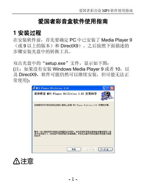
爱国者彩音盒软件使用指南1 安装过程在安装软件前,首先要确定PC中已安装了Media Player 9(或9以上的版本)和DirectX9)。
之后按照下面描述的步骤安装光盘中的转换工具。
双击光盘中的“setup.exe”文件,显示如下图:(注:如果没有安装Windows Media Player 9或者10,以及DirectX9,软件可能仍然可以继续安装,但可能无法正常使用):在安装软件前,首先要确定PC中已安装了Media Player 9(或9以上的版本)和DirectX9)单击“下一步”按钮,进入安装目录选择界面,如下图:确认路径后,单击“下一步”按钮,进入下一界面:单击“下一步”按钮,开始安装软件,显示进度如下图:软件安装完成,显示如下图:点击“下一步”按钮,进入下一界面:点击“关闭”按钮,完成软件的安装。
2 软件使用安装完成后,在“开始”菜单的“程序”中可以看到相应的程序,如下图所示:其中:MP3 Player Update Tool:MP3的固件升级工具;AMV Convert Tool:可以将其它格式的视频文件转换成可以在mp3中播放的*.AMV格式;AMV Player: AMV格式视频播放器,可以在计算机上播放转换获得的AMV视频文件;Sound Convert Tool:MP3播放器录音转换工具,本工具是将RCD/REC/ACT录音类型文件转换为WAV类型文件的工具,另外也包含回放WAV,MP3类型文档的功能Uninstall:卸载软件2.1 MP3 Player Update Tool升级操作步骤:进入主菜单,拨动MODE键选择“设定”短按MODE键进入“设定”,拨动MODE键选择“固件升级短按MODE键进入“固件升级”界面,将播放器联机到PC机进行固件升级运行PC端的升级工具“MP3 player Update”然后点击“选择新版本固件文件”按钮选择新的固件程序点击“开始升级”按钮,系统开始升级工作。
朗睿 LR035AR F系列彩色工业液晶显示器 说明书

LR035AR/F系列 彩色工业液晶显示器使用说明书上海朗睿电子科技有限公司本说明书仅适用于朗睿科技公司生产的LR035AR/F系列液晶显示器本公司产品已经通过ISO9001:2000质量体系认证!亲爱的用户:感谢您购买朗睿科技研制生产的LR035AR/F系列工业彩色液晶显示器!在您使用本产品前,请务必仔细阅读本使用说明书。
您能成为我们的用户,是我们莫大的荣幸。
为了使您尽快掌握朗睿液晶显示器的使用方法,我们特别为您编写了此说明书。
我们对产品说明书的编排力求全面而简捷。
从中您可以获得有关朗睿科技公司LR系列 3.5英寸工业彩色液晶显示器产品的配置、性能、操作的基本使用方法等方面的一些知识。
我们强烈建议您在使用本显示器之前,务必先仔细阅读,这会有助于您更好地使用本显示器。
如果您未按本说明书的要求操作显示器而由此引起的任何损失,朗睿科技公司将不承担责任。
我们已经尽我们最大的努力尽量避免人为的失误,以确保本说明书中所提供的信息是正确可靠的,但我们不能完全保证:不会有在印刷之前未曾发现或检查出的差错,以及那些我们无法控制环节上的疏漏,请您多加包涵!有时,我们为了提高显示器的整机性能和可靠性,可能会对产品的硬件和软件做一些小的调整,这样有可能会导致机器的实际情况与说明书有某些不一样的地方,但这不会实质性地影响您对显示器的使用,请您能够谅解!谢谢您的合作!朗睿科技公司目 录第一章简介 (3)1.1TFT LCD常用信号解释: (3)1.2特点 (3)1.3系统结构框图 (5)第二章性能与接口 (6)2.1性能参数 (6)2.2外部接口 (7)2.3拨码开关设置 (8)2.4通讯接口连线图 (9)第三章连接与通讯 (10)3.1连接方法 (10)3.2串行通讯 (10)3.3并行通讯 (13)第四章命令详解 (13)4.1命令详解 (13)4.2命令的位置 (33)第五章应用举例 (35)附录一、51汇编程序样例 (37)附录二、51汇编(并口)程序举例 (39)附录三、ASCII对照表 (41)第六章机械结构 (43)第七章其它 (44)一、售后支持说明 (44)二、运输损坏处理 (44)三、显示器的存储 (44)四、注意事项 (45)五、控制电路的注意事项 (46)第八章彩色LCD产品编码 (47)彩色LCD产品编码 (47)产品型号信息提取 (48)第一章简介本说明书提供了您所使用朗睿科技公司LR035AR/F系列工业液晶显示器的硬件和软件信息。
爱国者MP5 爱国者U303说明书

Philips 3000 Series Clock Radio R32051 用户手册说明书

Clock Radio3000 SeriesR3205User manual Register your product and get support at /supportContents1 Important 2Safety 22 Y our clock radio 3Introduction 3What's in the box 3Overview of the clock radio 33 Get started 4Install batteries 4Connect power 4Set time 44 Listen to FM radio 5Tune to FM radio stations 5Store FM radio stations manually 5Select a preset radio station 5Adjust volume 55 Other features 6Set alarm time 6Set sleep timer 66 Product information 77 T roubleshooting 78 Notice 81EN1 ImportantSafety• Read these instructions.• Heed all warnings.• Follow all instructions.• Do not block any ventilation openings.Install in accordance with the manufacturer’s instructions.• Do not install near any heat sources such as radiators,heat registers,stoves,or other apparatus (including amplifiers) that produce heat.• Protect the power cord from being walked on or pinched,particularly at plugs,convenience receptacles,and the point where they exit from the clock radio.• Only use attachments/accessories specified by the manufacturer.• Unplug this apparatus during lightning storms or when unused for long periods of time.• Refer all servicing to qualified service personnel.Servicing is required when the apparatus has been damaged in any way,such as power-supply cord or plug is damaged, liquid has been spilled or objects have fallen into the apparatus,the apparatus has been exposed to rain or moisture,does not operate normally,or has been dropped.• Battery usage CAUTION - T o prevent battery leakage which may result in bodily injury, property damage,or damage to the clock radio:• Install all batteries correctly,+ and - asmarked on the unit.• Remove batteries when the unit is notused for a long time.• The battery shall not be exposed toexcessive heat such as sunshine,fire orthe like.• This clock radio shall not be exposed to dripping or splashing.• Do not place any sources of danger on the clock radio (e.g.liquid filled objects,lighted candles).• Where the plug of the Direct Plug-in Adapter is used as the disconnect device, the disconnect device shall remain readily operable.2EN3EN 2 Y our clock radioCongratulations on your purchase, andwelcome to Philips! T o fully benefit from the support that Philips offers, register your product at /support.IntroductionWith this clock radio, you can • listen to FM radio;• set two alarms to ring at different times.What's in the boxCheck and identify the contents of your package:• Main unit• AC power adaptor • Quick start guide•Safety and Warranty leafletOverview of the clock radioa.• Turn on or switch to standby.b.PRESET / SET TIME• Store radio stations in memory.• Select a preset radio station.• Set time.c.HR / MIN / TUN• Tune to FM radio stations.• Set hour and minute.d.SNOOZE / SLEEP• Snooze alarm.• Set the sleep timer.e.Display panel• Display current status.f.AL1 / AL2 / VOL• Set alarm.• Adjust volume.1234654EN3 Get startedAlways follow the instructions in this chapter in sequence.Install batteriesThe batteries can only back up clock and alarmsettings.Insert 2 AAA batteries (not provided) withcorrect polarity (+/-) as illustrated.Connect powerSet time1 In standby mode, press and hold SET TIMEfor 2 seconds.2 Press HR to set hour and MIN to setminute, then press SET TIME to confirm.»The time is set.4 Listen to FMradioT une to FM radio stations1 Press to turn on the clock radio.2 Press and hold TUN for 2 seconds.»The clock radio tunes to a station with strong reception automatically.3 Repeat Step 2 to tune to more radio stations. T o tune to a station manually:Press TUN repeatedly to select a frequency.Store FM radio stations manually1 Tune to an FM radio station.2 Press and hold PRESET for 2 seconds toactivate programming mode.»The preset number begins to blink.3 Press TUN repeatedly to select a number.4 Press PRESET again to confirm.5 Repeat steps 1 to 4 to store more FM radiostations.Select a preset radio station In FM tuner mode,press PRESET repeatedly toselect a preset number.Adjust volumeWhile listening,press VOL to adjust volume.5EN5 Other features Set alarm timeSet alarm1 In standby mode,press and hold AL1 orAL2 for 2 seconds to set alarm time.2 Press HR to set hour and MIN to setminute,then press AL1 or AL2to confirm.Select alarm sourceY ou can select FM radio or buzzer as the alarm source by pressing AL1 or AL2 in standby mode.»The corresponding alarm icon lights up.Activate/deactivate alarm timer Press AL1 or AL2 repeatedly to activate or deactivate the alarm timer.»If the alarm timer is activated,the alarm indicator turns on.»If the alarm timer is deactivated,the alarm indicator turns off.»The alarm repeats ringing for the next day.»T o stop the alarm,press the corespondingAL1 or AL2.Snooze the alarmWhen the alarm sounds,press SNOOZE.»The alarm snoozes and repeats ringing 9 minutes later.Set sleep timerThis clock radio can switch to standby mode automatically after a preset period.• Press SLEEP repeatedly to select a period (in minutes).»The clock radio switches to standby mode automatically after the preset period.T o deactivate the sleep timer:• Press SLEEP repeatedly until [OFF] (off) appears.6EN6 Productinformation AmplifierRated Output Power200mW RMST uner (FM)Tuning Range87.5-108 MHzSignal to Noise Ratio >50 dBA General informationAC Power (power adaptor)Brand:Philips; Model:AS030-050-EE060 Input:100-240V~50/60 Hz;0.15A5V 0.6A(Main unit) 198.9 g 7 TroubleshootingT o keep the warranty valid,never try to repair the device yourself.If you encounter problems when using this device,check the following points before requesting service.If the problem remains unsolved,go to the Philips webpage (ww.philips. com/support).When you contact Philips,make sure that the device is nearby and the model number and serial number are available.No power• Make sure that the AC power plug of the unit is connected properly.• Make sure that there is power at the AC outlet. No sound• Adjust the volume.No response from the unit• Disconnect and reconnect the AC power plug,then turn on the unit again.Poor radio reception• Keep the clock radio away from other electronic devices to avoid radio interference.• Fully extend and adjust the position of the antenna. Alarm does not work• Set the clock/alarm correctly.Clock/alarm setting erased• Power has been interrupted or the power plug has been disconnected.• Reset the clock/alarm.7EN8 NoticeAny changes or modifications made to this device that are not expressly approved by MMD Hong Kong Holding Limited may void the user’s authority to operate the product. Hereby,TP Vision Europe BV declares thatthis product is in compliance with the essential requirements and other relevant provisionsof Directive 2014/53/EU.Y ou can find the Declaration of Conformity on/support.This product complies with the radio interference requirements of the European Community.This product is designed and manufactured with high-quality materials and components,which can be recycled and reused.This symbol means the product must not be discarded as household waste and should be delivered to an appropriate collection facility for recycling.Follow local rules and never dispose of the product and rechargeable batteries with normal household waste.Correct disposalof old products and rechargeable batteries helps prevent negative consequences for the environment and human health.This symbol means that the product contains batteries covered by European Directive 2013/56/EU which cannot be disposed of with normal household waste.Inform yourself about the the local separate collection system for electrical and electronic products and batteries.Follow local rules and never dispose of the product and batteries with normal household waste.Correct disposal of old products and batteries helps prevent negative consequences for the environment and human health.Removing the disposal batteriesT o remove the disposable batteries,see battery install section.8ENSpecifications are subject to change without notice.2020 © Philips and the Philips Shield Emblem are registered trademarksof Koninklijke Philips N.V. and are used under license. This product has been manufactured by and is sold under the responsibility of MMD Hong Kong Holding Limited or one of its affiliates, and MMD Hong Kong Holding Limited is the warrantor in relation to this product.TAR3205_12_UM_V1.0。
Precision 5530 服务手册说明书
Precision 5530服务手册9 2021注意、小心和警告:“注意”表示帮助您更好地使用该产品的重要信息。
:“小心”表示可能会损坏硬件或导致数据丢失,并告诉您如何避免此类问题。
:“警告”表示可能会导致财产损失、人身伤害甚至死亡。
© 2018 - 2019 Dell Inc. 或其子公司。
保留所有权利Dell、EMC 和其他商标均是 Dell Inc. 或其子公司的商标。
其他商标可能是其各自所有者的商标。
章 1: 拆装计算机内部组件 (6)安全说明 (6)关闭计算机— Windows 10 (6)拆装计算机内部组件之前 (7)拆装计算机内部组件之后 (7)章 2: 技术和组件 (8)处理器 (8)芯片组 (8)在 Windows 10 的设备管理器中识别芯片组 (8)内存特性 (9)验证系统内存 (9)在设置中验证系统内存 (9)显示器 (10)识别显示屏适配器 (10)更改的屏幕分辨率 (10)连接到外部显示设备 (11)硬盘驱动器 (11)在 Windows 10 中识别存储设备 (11)USB 功能 (11)HDMI 1.4 (13)章 3: 拆卸和重新组装 (14)基座盖 (14)卸下基座盖 (14)安装基座盖 (15)电池 (15)锂离子电池预防措施 (15)取出电池 (16)安装电池 (16)PCIe 固态驱动器 (SSD) (17)卸下 M.2 固态驱动器 - SSD (17)安装 M.2 固态驱动器 - SSD (18)扬声器 (18)卸下扬声器 (18)安装扬声器 (19)硬盘驱动器 (19)卸下 2.5 英寸硬盘驱动器 - 可选 (19)安装硬盘驱动器 - 可选 (21)键盘格架和键盘 (21)卸下键盘 (21)安装键盘 (23)WLAN 卡 (23)卸下 WLAN 卡 (23)目录3安装 WLAN 卡 (24)内存模块 (25)卸下内存模块 (25)安装内存模块 (25)散热器 (25)卸下散热器 (25)安装散热器 (26)系统风扇 (27)卸下风扇 (27)安装风扇 (29)电源连接器端口 (29)音频板 (30)卸下音频板 (30)安装音频板 (31)币形电池 (32)卸下币形电池 (32)安装币形电池 (33)电源按钮 (33)卸下电源按钮 (33)安装电源按钮 (34)带指纹识别器的电源按钮 - 可选 (34)卸下带指纹识别器的电源按钮 (34)安装带指纹识别器的电源按钮 (35)显示屏部件 (36)卸下显示屏部件 (36)安装显示屏部件 (37)天线护盖 (37)卸下天线 (37)安装天线护盖 (39)系统板 (39)卸下系统板 (39)安装系统板 (41)掌垫 (42)卸下掌垫部件 (42)安装掌垫部件 (44)章 4: 故障排除 (45)处理膨胀锂离子电池 (45)增强型预引导系统评估— ePSA 诊断程序 (45)运行 ePSA 诊断程序 (46)内置自检 (BIST) (46)M-BIST (46)LCD 电源导轨测试 (L-BIST) (47)液晶屏内置自检 (BIST) (47)哔声代码 (47)恢复操作系统 (47)实时时钟 (RTC) 重置 (48)备份介质和恢复选项 (48)WiFi 重启 (48)耗尽剩余弱电(执行硬重置) (48)4目录章 5: 获取帮助 (49)联系戴尔 (49)目录5拆装计算机内部组件安全说明前提条件遵循以下安全原则可防止您的计算机受到潜在损坏并确保您的人身安全。
ARM860_3530说明书

目录目录 (1)第1章EL-ARM-860实验系统的资源介绍 (3)板卡原理框图 (5)2.omap35xx cpu板扩展接口介绍 (6)3.内存映射 (8)4.启动设置说明 (10)三、omap35xx 大板介绍说明 (11)1.omap35xx 大板原理 (11)2、复位按键RK1、RK2、RK3 (11)3.按键接口介绍 (12)4.外接端口介绍 (12)4.1 USB端口介绍 (12)4.2 MMC/SD端口介绍 (13)4.3 语音端口介绍 (14)4.4 UART端口介绍 (14)4.5 LCD和触摸屏接口介绍 (15)4.6以太网接口介绍 (17)第4章基于linux操作系统的ARM系统实验 (30)实验一Linux的实验环境的搭建 (30)实验二BootLoader引导程序 (34)实验三linux的移植、内核、文件系统的生成与下载 (42)实验四linux驱动程序的编写 (52)实验五linux应用程序的编写 (57)实验六基于linux的键盘驱动程序的编写 (59)实验七基于linux的基本绘图应用程序的编写 (62)实验八基于linux的键盘应用程序的编写 (64)实验九基于linux的跑马灯应用程序的编写 (67)实验十USB播放mp3的实验 (70)实验十一MMC/SD卡实验 (72)实验十二TV OUT实验 (73)第1章 EL-ARM-860实验系统的资源介绍ARM实验箱硬件资源概述EL-ARM-860型教学实验系统属于一种综合的教学实验系统,该系统采用了目前在国内普遍认同的CPU:Omap35xx,32位微处理器,实现了多模块的应用实验。
它是集学习、应用编程、开发研究于一体ARM实验教学系统。
用户可根据自己的需求选用不同类型的CPU 适配板,兼容ARM7与ARM9及更高CPU,而不需要改变任何配置,同时,实验系统上的Tech_V 总线能够拓展较为丰富的实验接口板。
