中英文文献翻译-驱动桥
驱动桥汽车外文文献翻译、中英文翻译、外文翻译

Driving Axleautomobile driving axleThe driving axle is one of cross bars supporting a vehicle, on which the driving wheels turn .The driving axle includes a housing ,an axle drive ,a differential , tow axle shafts (half axles ),and final drives (if any ) .The axle .or main, drive is a drive-line unit that increases the torque delivered by the transmission and transmits it to the driving wheels, via the differential. In automobiles, the axle drive shaft, usually called the propeller shaft.The axle drive may be a Single or a double-stage type, the former comprising a pair of gears and the latter .tow pairs of gear. Drive pinion I may be made integral with its shaft, or it may be detachable from the shaft. Driving gears and are usually made in the form of detachable gear rings that are bolted or riveted to the differential case .Alex drive bevel pinions and gears are made with helical teeth in order to reduce noise in operation.The tow-stage axle drive consists of a pair of bevel gears and a pair of spur gears. Drive bevel pinion drives bevel gear that is fixed to the flange of the intermediate shaft made integral with 2nd–stage driving spur gear .Gears meshes with driven spur gear which is fastened to the case rotates in taper roller bearings installed in the differential carrier that makes part of the driving axle housing.The differential is a drive-line unit that divides the torque applied to it between the tow axle shafts and allows one driving wheel to turn at a different speed from the other.The differential consists of case, cross or spider pinion .and side gears, also known as axle gears .the differential pinions are freely mounted on the cylindrical arms of the spider, which is held in the differential case, and remain in constant mesh with the differential side gears.When the automobile is moving down a straight and even road, both driving wheels meet with one and the same rolling resistance. In this case, axle driven gear, or differential ring gear, causes the differential case to rotate .when the differential case rotates pinions and their spider arms move around in a circle with tow differential side gears are meshed with the pinions, the side gears must rotate, causing the axle shafts and their associated driving wheels to turn. With equal resistance applied to each wheel, the differential pinions do not rotate. They apply equal torque to the side gears and therefore both driving wheels rotate at one and the same speed is unequal ,the differential pinions rotate on their spider arms as well as drive round with the differential case .supposing that one of the axle shaft is prevented from rotating ,the differential pinions would have to walk around the stationary side gear ,causing the other side gear to rotate at twice its normal speed .You can now see how the differential can allow one driving wheel to turn faster than the other .Whenever the automobile goes around a turn ,the outer driving wheel travels a greater distance than the inner drive wheel .the inner wheel speeds up proportionately ,thanks to the differential pinions that rotate on their spider arms and ,rolling around the slower side gear send more rotary motion to the outside wheel.The differential side gears are splined on to the inner ends of the axle shafts .The other ends of the shafts are attached to the driving wheel hubs by means of flanges .Trucks use full floating axle shafts .Such axle shafts are acted upon by torque only .All the other loads acting on the driving wheels are taken by the driving axle housing, because the wheel hubs are supported by bearings mounted on the housing.Driving axle of general-purpose wheeled tractorGeneral-purpose wheeled tractors are a four-wheel drive type, they have tow driving axles-front and rear .Both axles are similar in construction, expect for the housing. Each driving axle consist if a housing, an axle drive ,a differential ,and final drives .The front and rear-axles drives are interchangeable and comprise a pair of spiral bevel gears . The axle drive pinion is made integral with a shaft that issupported by tow taper roller bearings installed in axle drive pinion carrier .The latter is accommodated in differential carrier and is fixed to it by bolts. The flange of the axle drive pinion carrier is provided with threaded holes to fit puller screws that are used to remove the axle drive pinion carrier from the differential carrier .The position of the drive pinion relative to the centerline of the axle is adjust by means of a pack of shims placed under the flange of the drive pinion carrier Shims palace under the cone of the front bearing are used to adjust the preload on the drive pinion bearings. Splined to adjust the preload on the drive pinion shaft is universal-joint flange .The axle drive gear is bolted to the differential case flange.THE DIFFERENTIAL consists of case, four pinions, and tow side gears .The differential case comprise tow halves that are bolted together and supported by taper roller bearings installed in the differential carrier .Screwed in the bearings housing from the outside are nuts used to adjust the backlash between the ring gear and drive pinion teeth and the side bearing preload.Welded to the top of the driving axle housing at both its ends are spring pads .The housing of both its ends are spring axels are provided with filler ,overflow ,and drain holes closed by plugs .Both housing also have vents ,The rotating components of the driving axles are lubricated with transmission oil .As distinct from the automobiles considered in this text, all tractors include final drives in their power trains .The final drives of general-purpose wheel tractors are referred to as wheel-hub reduction gears.While transmitting power to the driving wheels, wheel-hub reduction can increase their torque .These are planetary reduction gear sets consist of sun gear ,or wheel ,three planet ,or pinion ,gears ,planet or pinion ,carrier .stationary internal ,or ring ,gear ,and housing.The sun gear is splined to the outer end of the axle shaft is splined to the differential side gear .The cylindrical planet gears are in constant mesh with both the sun gear and the ring gear and are free to rotate on roller bearings mounted on shafts that are attached to the planet carrier .The planet carrier is fasted to the reduction gear housing by means of studs and nuts .The flange of housing ,driving wheel brake drum13,and wheel hub are clamped together by bolts .The planet carrier and reduction gear housing form the driven part of the planetary gear set and rotate with the driving wheel of the tractor .The driving gear hub is supported by taper roller bearings mounted on axle shaft housing ,or axle sleeve .The axle sleeve is connected to the stationary ring gear by means of adapter hub that has internal splines and external teeth . The splines are meshed with matching splines on the axle sleeve, and the teeth are meshed with internal teeth ring gear.Wheels and its maintainModern wheeled tractors and automobiles use pneumatic-tired disc wheels. As a result of the driving wheel tires gripping the road, the rotary motion of the wheels is transformed into the translational motion of the tractor or automobile.According to their purpose, wheels are classified as driving .driven steerable, and combination types.Trucks and general-purpose wheeled tractors have all their wheels of one and the same size .Row-crop tractors have their rear wheels larger than the front wheels .The rear wheels carry the major proportion of the load due to the weight of the tractor .The front wheels are loaded lighter and this makes them easier to turn and provide good directional steering stability, which is essential for row-crop work.A TRUCK WHEEL consists of disc and flat base rim that is made integral with it, while the other flange is formed by detachable side ring that is held to the rim by split lock ring on the rim .which doubles as a side ring and a lock ring.The wheel disc is provided with holes for mounting the wheel on the wheel mounting bolts ,or wheel studs ,on the wheel hub ,where it is fixed by nuts .Both the holes and the nuts are tapered to ensure exact location of the wheel on its hub .The rear driving axles of trucks carry tow wheels at each end .The inner wheels are held to the hubs by cap nuts that are threaded both on the inside and on the outside .and the outer wheels are mounted on the cap nuts and fixed in place by taper nuts screwed on the nuts .The wheel nuts on the right side of truck have right-hand threads, whereas the nuts on the left side of the truck are threaded left-hand .The reason is to tighten the nuts, not loosen them, and thus prevent them from working loose on acceleration andbraking.An automobile pneumatic tire consists of casing, inner tube, and flap .The tire casing comprises tread, side walls, and beads .Tires for good roads use small tread patterns, while those for bad roads or cross –country service large tread patterns.The inner tube is made in the form of a hollow elastic rubber doughnut that is inflated with air after it is installed inside the tire and the tire is put on the wheel rim .The inner tube is inflated through tire valve that consists of housing 11,valve inside ,and cap .The valve housing is made of brass in the dorm of a flanged tube that is mounted in the inner tube by means of a washer and a nut and sticks out through a hole in the wheel .Some tire valve housing are of comprise construction :the upper part is made of brass and the lower part ,of rubber that is vulcanized on to the inner tube .The valve inside is a check valve that opens to let air in the inner tube when an air closed ,spring pressure and air pressure inside the tube hold the valve .When the valve is closed ,spring pressure and air pressure inside the tube hold the valve in its seat .It includes core with a rubber ring ,a plunger pin ,and a spring .The valve inside is Screwed in the tire valve housing and is closed by the cap Screwed on the housing.To the construction of the driving and steerable wheels, each wheel comprises hub , disc with rim ,and tire with inner tube .The rim is welded to the disc and the disc is bolted to the hub .The driving wheel tires are of low-pressure type and have heavy tread bars for better traction.The driving wheel hub is keyed to axle shaft and is fixed in place by means of bolted-on insert with worm whose threads mesh with the rack teeth cut in the half axle .By turning the worm one can change the position of the wheel on the axle shaft to obtain the desired track width .Before doing this ,it is necessary to jack up the rear part of the tractor to clear the wheels of the ground and loosen the bolts that hold the inserts to the wheels hubs .Should this adjustment prove insufficient ,the track width can further be increased by placing the wheels with the concaves of their discs facing inwards.On some row-crop tractors ,the rear wheel discs are bolts to lugs welded on the wheel rims .In this case ,the crack width can be changed by bolts the discs in alternative positions to the lugs .Also the concave wheel discs may be used either with the concave facing inwards or outwards.Trouble-free operation of automobiles and wheeled tractors largely depends on the condition of the tires. Therefore, during operation, one should adhere to following rules.Prevent fuel and, or oil from getting onto the tires. Cleans the tires regularly from dirt and remove all foreign articles, such as stones, form the treads. Do not apply brakes sharply, never start away form rest with a jerk, and avoid making sharp turns, for all this causes uneven wear of the tires. Do not allow excessive slipping of the driving wheels. When preparing your tractor or automobile for a long-term storage, jack up the wheels and put trestles under the axles or frame to relieve the tires.The service life of tires is expressed in terms of their mileage. For most bias (ordinary) truck tires, the guaranteed mileage amounts to 50000 km. Observing the above rules will help prolong the useful service life of tires.驱动桥汽车的驱动桥驱动桥是一个支撑车辆的十字交叉的轴,它可以驱动车轮运动。
自动变速器与驱动桥概述 英文文献加中文翻译
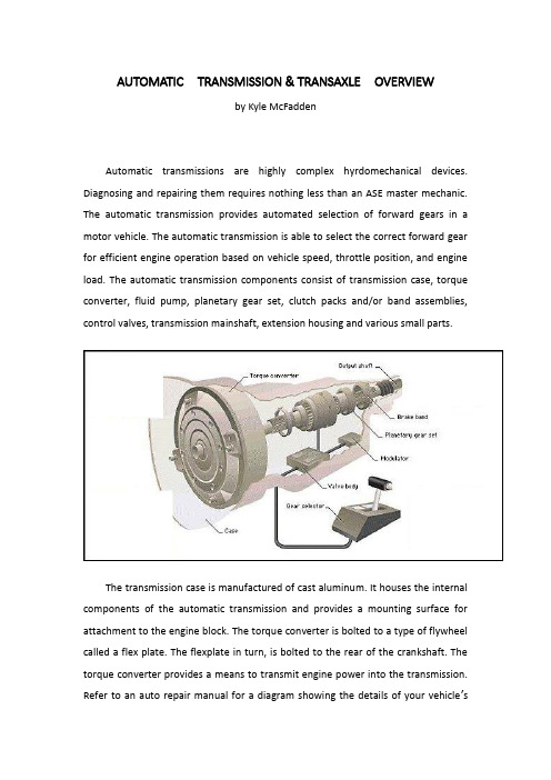
AUTOMATIC TRANSMISSION & TRANSAXLEOVERVIEWby Kyle McFaddenAutomatic transmissions are highly complex hyrdomechanical devices. Diagnosing and repairing them requires nothing less than an ASE master mechanic. The automatic transmission provides automated selection of forward gears in a motor vehicle. The automatic transmission is able to select the correct forward gear for efficient engine operation based on vehicle speed, throttle position, and engine load. The automatic transmission components consist of transmission case, torque converter, fluid pump, planetary gear set, clutch packs and/or band assemblies, control valves, transmission mainshaft, extension housing and various small parts.The transmission case is manufactured of cast aluminum. It houses the internal components of the automatic transmission and provides a mounting surface for attachment to the engine block. The torque converter is bolted to a type of flywheel called a flex plate. The flexplate in turn, is bolted to the rear of the crankshaft. The torque converter provides a means to transmit engine power into the transmission.Refer to an auto repair manual for a diagram showing the details of your vehicle’s torque converter assembly.The torque converter is a doughnut shaped device that is filled with fluid. When the engine is running, the torque converter spins, rotating and pressurizing the fluid using internally mounted blades. The spinning fluid rotates a turbine that is connected to the transmission mainshaft. A separate internal set of blades called a stator helps to direct the fluid into the turbine. The operation of the torque converter can be compared to a powered air fan spinning a non powered air fan. The powered fan will generate moving air, directed at the non powered fan blade, causing it to rotate. The powered fan becomes the driving member, while the non powered fan becomes the driven member. If the air is moving slow enough, very little torque is transmitted from the driving member to the driven member. If you wanted, you could easily stop the rotating fan blade of the non powered fan. However, if the powered fan were to operate at high speed, the non powered fan would be rotating at a much higher speed, making it more difficult to stop. This is the same principal that allows an automatic transmission equipped vehicle to idle in gearand drive down the road without using a mechanical clutch. At idle speed, fluid pressure is low, transmitting very little engine torque through the transmission. When the engine speed is raised, fluid speed and pressure increases, allowing more engine torque to be directed to the transmission. Most torque converters contain an internal locking clutch that is applied at cruise speed. This clutch, called a torque converter clutch, eliminates the slippage that occurs with a torque converter. The torque converter clutch is used as a fuel saving device, and to reduce the amount of heat generated in the transmission. When troubleshooting poor MPG issues, one culprit is a faulty torque converter, though poor MPG would also be present with shifting issues if the torque converter is the cause.Forward speeds and reverse are provided by a gear set called the planetary gears. The planetary gear set consists of a central gear, called the sun gear, placed inside a large gear called an internal gear. Rotating between the internal gear and the sun gear, are small gears, held in a carrier, known as planetary gears. Different gear ratios are made possible by holding one component of the planetary gear set and allowing the other to rotate. For example, if the sun gear were held, the internal gear would be rotated by the planetary gears revolving around the motionless sun gear. This would cause the internal gear to rotate at low speed, while the planetary gears move much faster. This would provide a low gear function for the transmission, since the slow moving internal gear would be used to transmit power to the driving wheels.An internal transmission oil pump is driven by the rotation of the torque converter. The oil pump pressurizes and circulates the transmission fluid used for the operation and lubrication of the transmission. The pressure created by the pump is often referred to as line pressure. Line pressure is utilized by the transmission to signal shift points and operate various transmission components.Bands and clutches are used to hold the components of the planetary gear set to in order to provide different forward gear ratios or reverse. They are operated by line pressure that is directed to a specific band or clutch pack by the transmission shift control valves. The shift control valves operate by responding to changes in linepressure based upon the operation of input devices that signal road speed, throttle position, and engine load. Correcting shifting issues may not involve a costly auto repair job; it may be as simply as adjusting the bands.The input devices used for transmission shift control are the governor, throttle valve, and vacuum modulator. The governor provides road speed information to the transmission to control shift points. It works by increasing line pressure as road speed increases. The throttle valve is connected by linkage to the throttle of the engine. The throttle valve modifies line pressure based on throttle position. This information is needed to vary shift points in response to driving conditions. When the throttle is moved to wide open, the throttle valve will cause send a line pressure signal to the control valves to delay shifting until higher road speed. The vacuum modulator changes shift feel in response to engine load. Since engine intake manifold vacuum changes in response to engine load, manifold vacuum is used as an input signal to the transmission. The vacuum modulator receives vacuum signal from the engine. The vacuum modulator will increase line pressure to stiffen transmission shifting based during heavy engine loads. The increased line pressure will cause clutches and bands to hold tighter and help to diminish slipping.Most vehicles today are equipped with automatic transmissions that use electronic shift controls. The operation of the electronically controlled transmission is similar in principle to the non electric transmission. However, the electronically shifted transmission uses input signals from the vehicle control module to control shift points, rather than a governor and throttle valve. The vehicle control module controls transmission shifting based on engine and transmission data sensors. The throttle position sensor is used in place of the mechanical throttle valve. The vehicle speed sensor is used to replace the governor. Engine load sensors, such as a manifold pressure sensor, are used to control shift feel. A vacuum modulator may still be used by some vehicle makes to assist in shift control. The vehicle control module will utilize this information to operate various shift control solenoids inside the transmission. These shift control solenoids in turn control line pressure to theirrespective shift control valves that in turn apply or release pressure to bands or clutches.The result of using electronic shift controls is an automatic transmission that operates more efficiently to tailor shifting to meet engine demands. Fuel economy and vehicle emission control are enhanced by more precise control of the automatic transmission. Vehicle control modules have the ability to adapt transmission shifting to meet the individual driving patterns of the vehicle. Also internal overheat protection is provided for by the control module’s ability to monitor transmission fluid temperature and change transmission shifting and operation to minimize temperature related damage. On many vehicles, the EEC (Electronic Engine Control) will “learn” a particular driver’s driving style. This information is stored in the EEC’s memory. If the battery is disconnected (during replacement, for example), the vehicle may shift erratically for a short time until the EEC re-learns the driver’s driving style and then reprograms itself. This is important to remember and a little patience can save you a trip to the auto repair shop, ie. after your battery is replaced, drive your vehicle for a day or so and see if the erratic shifting issue is resolved (most likely it will correct itself).The automatic transaxle is an automatic transmission that also contains the final drive for delivering power to the driving wheels. Operation is comparable to the operation of the conventional automatic transmission. With the exception of a differential and axle shafts located in the lower portion of the transaxle. The automatic transaxle is used almost exclusively in front wheel drive vehicles..自动变速器与驱动桥概述自动变速器是高度复杂的精密设备。
中英文文献翻译—重型越野汽车断开式驱动桥的研发
附录附录AHeavy Off-Road Vehicle Drive Axle Of BreakingThe important thing is, in the great assembly at the end of the transmission. Its basic function is increased by the transmission shaft or directly by the torque, came to the torque distribution to left and right drive wheels, and make the right and left wheel drive car has required the kinematics differential function, While carrying the spring load and the car wheel, the frame of the body through suspension or integral to plumb-lines, longitudinal and transverse force and moment force, Also the biggest transfer transmission torque, still under the bridge housing reaction torque.Drive structure and driving wheel is closely related to the suspension structure. When driving wheel using an independent suspension, using the broken open axles, When driving wheels adopt independent suspension, match with breaking drive axles, independent suspension. Look from exterior, independent suspension axles connectionless left and right of the whole bridge rigid driving wheel, shell is bridge housing, and other relative movement between. This bridge is installed in the middle frame or integral car transmission and driving wheel transmission device and part of the quality of the automobile suspension with belong to the quality and the side of the drive wheels with independent suspension of elastic component and frame or weak connection for cars. Therefore, one on either side of the drive wheels can independently, relative to the frame or cars do, swing, left, and right shaft corresponding requirements and their corresponding shell makes the corresponding swing. Cars drive by breaking the suspension, and the quality of small and independent suspension matching, can make the driving wheels of various earthing and adaptability, good roads that can greatly reduce the cars in the rough road impact and vibration during the body decreases wheel and axle tilt, the dynamic loads of vehicle, improve and enhance average speed, Reduce the damage, improve its components reliability and prolong its service life.Based on the development of China's heavy independent suspension of six x 6 cross-country car cut off from the drive axles, for example, is insufficient, the development technology independent suspension drive axle of necessity and independent suspensiondrive axle of structural principle in aspects of heavy off-road vehicle drive with independent suspension of this development.1 Domestic independent suspension drive technology situationAt present domestic independent suspension axles in cars, light off-road vehicle and JN252 8 x 8, etc ZhongDunWei military car has been applied and independent suspension heavy off-road vehicle axles technology is basically blank, Foreign independent suspension heavy off-road vehicle axles technology also only by American company, belarus, Minsk Sisu, Finland has TIMONEY company and Korea etc, and application scope of military and civilian limitations in some special models.2 Develop independent suspension drive axle of necessityIn recent years, with independent suspension off-road vehicle market demand more and more widely. Restrict independent suspension off-road vehicle development is one of the key factors, thus breaking drive axles of the necessity of developing broken off.2.1Military car development needsCurrently our extensive use of grade 6 x 6 type 7t SX2190 models is shaanxi automobile manufacturing factory using STEYR technology development of new generation rover, has good performance, and strong adaptability, good performance advantages over the past 20 years for national defense construction made great contribution. The truck with 8 x 8 upward-leading continuous casting.the JN2270 15t and capability of type x 8 August JN2300 type, the successful development of China's second DaiJun car development was at an end. In order to adapt to the needs of modern war, the third DaiJun car development was put on the agenda. Article DaiJun car features for independent suspension of high performance of motor vehicles. As its core technology is one of the big Hollywood drive shaft cut off, domestic blank, basic is dependence on imports, if do not accord with national also does not conform to the military.2.2The basic needs of national constructionFor many years, our national economy is developing rapidly, and infrastructure investment growth, hydroelectric power, oil field, mine, coal and other industries such as fire like tea. The industry is inseparable from the high quality, the high performance of transport vehicles, independent suspension off-road vehicle is among the top. However, these vehicles almost entirely on imports, spent a great deal of foreign exchange. To develop a replacement model is of great significance to meet the market demand.3 Independent suspension structure theory. Drive axle ofChina's heavy automobile group company with development and production status, independent development drive axle of the independent suspension 6 x 6 cross-country car drive shaft cut off big Hollywood. According to 6 x 6 independent suspension chassis design requirements, in this model adopted high transmission fault type axles. The first thing is to cut off to drive, high of double bridge for breaking through the medium-sized Bridges, rear axles turn for breaking steering of high axles. Three bridge are installed with gas control differential between the wheel lock differential, medium-sized Bridges across the bridge box installed with gas control differential between the lock shaft differential. Main reducer ratio for 1 2023, gear ratio for 4. 26 (belt wheel side filling put gas system, ABS), the total ratio 7.016, The medium-sized Bridges for Φ 180 input end tooth flanges, output for Φ 165 end flange, rear axle gears before the input for Φ 165 end tooth flange, Each shaft axis for jose 13t. This design is mainly in steyr drive technology based on the development and design, design thoughts and 6 x is 6, 8 x 8, 10 December 10, military USES 10 series assemblies, reduce the new design of special parts. 8 x 8 middle bridge, 10 assembly, 10, and 12 million spxillion structure types are similar. The new design two broken open bridge, front axle shell adopts the breakthrough in the shell, type of bridge, using the same type of the rear axle housing learnings. On the basis of that, left, right, two kinds of half axle and cover and spline set assembly, and on the reduction and bridge box shell and the local improvement. High technology to drive the corresponding design. Before using high to drive axle of bridge structure, thus make the box with the same drive axle of center distance of the bridge, i.e. input than the original structure of flange steyr 100mm up front axle and bridge, can satisfy the same height flange vehicle transmission Angle to decorate the small request. Before turning mainly by high drive axles, before breaking casting bridge in the middle of the disc brake, using the shell with the filling of the deflated wheelhub ball cage patterned assembly, universal shaft coupling assembly etc. And now the thing turn compared with has the following characteristics: ①Using steel bridge housing, good rigidity, high strength.②Using steyr mature main reducer and axle box of bridge structure of the existing technology (without prior to drive axle box structure), improve cross the bridge reliability.③Using the ball cage patterned double gimbal couplings, can make the centerline of ball cage with to the center of the kingpin always in line with the wheels, reduce sliding wear.4 conclusionWith independent suspension car of rapid development, large-tonnage breaking drive axle of development of necessity and urgency. It not only can greatly improve the car ride and mobility, also for automobile driving performance such as power, economy, and has a direct impact on the stability, etc. Both can satisfy the military modernization needs, also can meet the needs of the development of national economy, therefore has the important practical significance.附录B重型越野汽车断开式驱动桥的研发驱动桥是汽车的重要大总成 ,处于传动系的末端。
驱动桥汽车外文文献翻译、中英文翻译、外文翻译
驱动桥汽车外文文献翻译、中英文翻译、外文翻译The driving axle is an essential component of a ___。
It consists of several parts。
including a housing。
axle drive。
differential。
two axle shafts。
and final drives if necessary.The main purpose of the axle drive is to ___。
___.There are two types of axle drives: single and double-stage。
The single-stage type has a pair of gears。
while the double-stage type has two pairs of gears。
The drive ___ case。
To ce noise during n。
axle drive ___.In summary。
___。
It includes several components that work ___ to the wheels。
The axle drive shaft is an essential part of the axle drive。
and there are two types of axle drives。
To ce noise during n。
the driving gears are made with ___.When a car turns。
___ a greater distance than the inner ___。
thanks to the differential ns ___ around the slower side gear。
the inner ___。
驱动桥5000字外文翻译文献
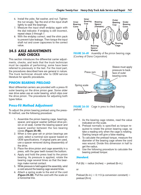
As the bearing cage rotates, read the value7. indicated on the scale.Preload normally is specified as torque re-8. quired to rotate the pinion bearing cage, so take a reading only when the cage is rotating. Starting torque will give a false reading.To calculate the preload torque, measure the 9. diameter of the bearing cage where the cord was wound. Divide this dimension in half to get the radius.10. U se the following procedure to calculate thebearing preload torque:Standard.Pull (lb) 3 radius (inches) 5 preload (lb-in.)orPreload (lb-in.) 3 0.113 (a conversion constant) 5 preload (N .m)Install the yoke, flat washer, and nut. Tighten 6. the nut snugly. Tap the end of the input shaft lightly to seat the bearings.Measure the input shaft endplay again with 7. the dial indicator. If endplay is still incorrect, repeat steps 3 through 7.With the endplay correct, seal the shim pack 8. to prevent lube leakage. Then torque the i nput shaft nut and cover capscrews to the correct value.24.5 A XLE ADJUSTMENTSAND CHECKSThis section introduces the differential carrier adjust-ments, checks, and tests that the truck technician must be capable of performing; some have beenr eferred to previously in the text. For the most part, the procedures described here are general in nature. The truck technician should refer to OEM servicel iterature for specific procedures.PINION BEARING PRELOADMost differential carriers are provided with a press-fit outer bearing on the drive pinion gear. Some older rear drive axles use an outer bearing, which slips over the drive pinion. The procedures for adjusting both types follow.Press-Fit Method AdjustmentTo adjust the pinion bearing preload using the press-fit method, use the following procedure:Assemble the pinion bearing cage, bearings, 1. spacer, and spacer washer (without drive pin-ion or oil seal). Center the bearing spacer and spacer washer between the two bearing cones (Figure 24–49).When a new gear set or pinion bearings are 2. used, select a nominal size spacer based on OEM specifications. If original parts are used, use a spacer removed during disassembly of the drive.Place the drive pinion and cage assembly in a 3. press, with the gear teeth toward the bottom.Apply and hold the press load to the pinion 4. bearing. As pressure is applied, rotate the bearing cage several times so that the bear-ings make normal contact.While pressure is held against the assembly, wind 5. a cord around the bearing cage several times.Attach a spring scale to the end of the cord 6. (Figure 24–50). Pull the cord with the scale ona horizontal line.FIGURE 24–49 Assembly of the pinion bearing cage.(Courtesy of Dana Corporation)FIGURE 24–50 Cage in press to check bearingp reload.Sleeve must applymust be against the outer bearing. If the fit between the yoke or flange splines and drive pinion splines is tight, use a press to install the yoke or flange (Figure 24–51).Temporarily install the drive pinion and cage 4. assembly in the carrier (Figure 24–52). Do not install shims under the bearing cage.Install the bearing cage to the carrier cap-5. screws. Washers are not required at this time. Hand-tighten the capscrews.Fasten a yoke or flange bar to the yoke or 6. flange (Figure 24–53). The bar will hold the drive pinion in position when the nut ist ightened.Metric.Pull (kg) 3 radius (cm) 5 preload (kg-cm) orPreload (kg-cm) 3 0.098 (a conversion constant) 5 preload (N .m)Examples. We can convert the foregoing equa-tions into examples by applying some data to them:Standard7.5 lb 3 3.31 in. 5 24.8 lb-in. (preload) or24.8 lb-in. 3 0.113 5 2.8 N .m (preload)Metric3.4 kg 3 8.4 cm 5 28.6 kg-cm (preload) or28.6 kg-cm 3 0.098 5 2.8 N .m (preload)11. I f necessary, adjust the pinion bearing preloadby changing the pinion bearing spacer. A thicker spacer will decrease preload, whereas a thinner spacer will increase the preload.12. O nce the correct bearing preload has beenestablished, note the spacer size used. Select a spacer 0.001 inch (0.025 mm) larger for use in the final pinion bearing cage assembly pro-cedures. The larger spacer compensates for slight expansion of the bearing, which occurs when pressed on the pinion shank. The trial spacer pack should result in correct pinion bearing preload in three times out of four cases.Y oke Method of AdjustmentTo adjust the pinion bearing preload using the yoke or flange method, proceed as follows:Assemble the complete pinion bearing cage 1. as recommended in the press-fit method.A forward axle pinion is equipped with a heli-2. cal gear. For easier disassembly during bear-ing adjustment procedures, use a dummy yoke (if available) in place of the helical gear.Install the input yoke or flange, nut, and 3.washer on the drive pinion. The yoke or flangeFIGURE 24–51 Using a press to install the yoke orflange to the drive pinion. (Courtesy of Arvin Meritor)FIGURE 24–52 Install the pinion and cage assembly in the carrier housing. (Courtesy of Arvin Meritor)indicated on the torque wrench (see Figure 24–55). Typical value is 50 lb-ft. (68 N .m)m aximum applied to one side gear.If the torque value exceeds the specification, 5. disassemble the differential gears from the case halves.Check the case halves, spider, gears, and 6. thrust washers for the problem that caused the torque value to exceed specifications. Re-pair or replace defective parts as required. Remove any foreign debris.Check/Adjust Pinion Cage Shim PackThis procedure is used to check and adjust the thick-ness of the shim pack used in the pinion bearing cage. Use this procedure if a new drive pinion and crownTighten the nut on the drive pinion to specifi-7. cation, typically 400 to 700 lb-ft. (542 to 950 N .m).Remove the yoke or flange bar.8. Attach a torque wrench to the drive pinion 9. nut. Rotate the drive pinion and read the value indicated on the torque wrench. Preload is correct when the torque required to rotate the pinion bearing cage is from 15 to 35 lb-in. (1.7 to 4.0 N .m).To adjust the pinion bearing preload, disas-10. semble the pinion bearing cage and change the pinion bearing spacer size. A thicker spacer will decrease preload, whereas a thin-ner spacer will increase preload.Differential Rolling ResistanceA check to measure and establish differential rolling resistance follows. To perform this check, a special tool must be made. You can easily make this tool from an old axle shaft that matches the spline size of the differential side gear. Figure 24–54 illustrates the fab-rication specifications for this special tool.To check differential resistance to rotation, use the following procedure:Install soft metal covers over the vise jaws to 1. protect the ring gear (Figure 24–55).Place the differential and crown gear assem-2. bly in the vise.Install the special tool into the differential until 3. the splines of the tool and one side gear are engaged.Attach a torque wrench to the nut of the spe-4. cial tool and rotate the differential gears. As the differential gears rotate, read the valueFIGURE 24–55 Reading the torque value to check the rolling resistance. (Courtesy of Arvin Meritor)FIGURE 24–53 Using a flange bar to hold the drivepinion in position. (Courtesy of Arvin Meritor)FIGURE 24–54 Fabrication details for a tool to checkthe rolling resistance. (Courtesy of Arvin Meritor)If the new pinion cone number is a minus (–), sub-8. tract the number from the standard shim packthickness that was calculated in step 3 or 4.The value calculated in step 7 or 8 is the 9.t hickness of the new shim pack that will bei nstalled. Figure 24–59 illustrates several e xamples of determining shim pack t hickness.Install the drive pinion, bearing cage, and new10. shim pack into the differential carrier.gear set is to be installed, or if the depth of the drive pinion has to be adjusted. You are checking the rolling resistance using a torque wrench.To check/adjust the shim pack thickness (Figure 24–56), do the following:With a micrometer, measure the thickness of 1. the old shim pack removed from under the pinion cage (Figure 24–57). Record the mea-surement for later use.Look at the pinion cone (PC) variation number 2. on the drive pinion being replaced (Figure 24–58). Record this number for later use also.If the old pinion cone number is a plus (+), 3. subtract the number from the old shim pack thickness that was recorded in step 1.If the old pinion cone number is a minus (–), 4. add the number to the old shim thickness that was measured in step 1.The value calculated in step 3 or 4 is the 5.t hickness of the standard shim pack without variation.Look at the PC variation number on the new 6. drive pinion that will be installed. Record the number for later use.If the new pinion cone number is a plus (+), 7. add the number to the standard shim packthickness that was calculated in step 3 or 4.FIGURE 24–56 Drive pinion depth controlled by shimpack thickness. (Courtesy of Arvin Meritor)FIGURE 24–57 Measuring the thickness of the old shim pack. Mike each shim individually then add tocalculate total thickness. (Courtesy of Arvin Meritor)FIGURE 24–58 Location of the pinion cone (PC)v ariation number. (Courtesy of Arvin Meritor)Adjust Differential Bearing PreloadOne of two methods can be used to check and adjust the preload of the differential bearings.Method One.Attach a dial indicator onto the mounting 1. flange of the carrier and adjust the indicator so that the plunger rides on the back surface of the crown ring gear (Figure 24–60).Loosen the bearing adjusting ring that is op-2. posite the ring gear so that a small amount of endplay is indicated on the dial indicator. To turn the adjusting rings, use a T-bar wrench that engages two or more opposite notches in the ring (Figure 24–61).Move the differential and crown gear to the 3. left and right using prybars as you read the dial indicator. Use two prybars that fit be-tween the bearing adjusting rings and the ends of the differential case (Figure 24–62). You also can use two prybars between the differential case or crown gear and the carrier at locations other than those just described. In either case, the prybars must not touch the differential bearings.EXAMPLES:Inchesmm 1.Old Shim Pack Thickness Old PC Number, PC +2Standard Shim Pack Thickness New PC Number, PC +5New Shim Pack Thickness .030.76–.002–.05.028.71+.005+.13.033.842.Old Shim Pack Thickness Old PC Number, PC –2Standard Shim Pack Thickness New PC Number, PC +5New Shim Pack Thickness .030.76+.002+.05.032.81+.005+.13.037.943.Old Shim Pack Thickness Old PC Number, PC +2Standard Shim Pack Thickness New PC Number, PC –5New Shim Pack Thickness .030.76–.002–.05.028.71–.005–.13.023.584.Old Shim Pack Thickness Old PC Number, PC –2Standard Shim Pack Thickness New PC Number, PC –5New Shim Pack Thickness.030.76+.002+.05.032.81–.005–.13.027.68FIGURE 24–59 Determining shim pack thickness.(Courtesy of ArvinMeritor Inc.)FIGURE 24–60 Dial indicator attached to carrier-mounted flange. (Courtesy of Arvin Meritor)FIGURE 24–61 Turning the adjusting ring using aT-bar wrench. (Courtesy of Arvin Meritor)FIGURE 24–62 Using pry bars to adjust play in the crown gear. (Courtesy of Arvin Meritor)Tighten the same bearing adjusting ring4.so that no endplay shows on the diali ndicator.Move the differential and crown gear to the5.left and right as needed. Repeat step 3 untilzero endplay is achieved.Tighten each bearing adjusting ring one6.notch from the zero endplay measured instep 4.Method Two.A second method of checking pre-load is to measure the expansion between the bearing caps after you tighten the adjusting rings. Use the following procedure:Turn both adjusting rings hand tight against1.the differential bearings.Measure the distance X or Y between oppo-2.site surfaces of the bearing caps (Figure24–63A) using a large micrometer of thec orrect size (Figure 24–63B). Make a note ofthe m easurement.Tighten each bearing adjusting ring one3.notch.Measure the distance X or Y again. Compare4.the dimension with the distance X or Y mea-sured in step 2. The difference between thetwo dimensions is the amount that the bear-ing caps have expanded.Example: Measurements of a carrier.Distance X or Y before tightening adjusting rings5 15.315 inches (389.00 mm)Distance X or Y after tightening adjusting rings5 15.324 inches (389.23 mm)15.324 inches minus 15.315 inches5 0.009 inch (0.23 mm) differenceIf the dimension is less than specification, repeat steps 3 and 4 as needed.Crown Gear Runout CheckTo check the runout of the crown/ring gear, do the f ollowing:Attach a dial indicator on the mounting flange1.of the differential carrier (Figure 24–64).Adjust the dial indicator so that the plunger or2.pointer is against the back surface of thecrown gear.FIGURE 24–63 (A) Location of distances measured to check expansion between bearing caps aftert ightening adjusting rings; (B) measuring this distance.(Courtesy of Arvin Meritor)FIGURE 24–64 Checking crown gear runout. (Courtesy of Arvin Meritor)Pinion and Crown Tooth ContactA djustment Correct tooth contact between the pinion and crown gear cannot be overemphasized, because improper tooth contact results in noisy operation and prema-ture failure. The tooth contact pattern consists of the lengthwise bearing (along the tooth of the ring gear) and the profile bearing (up and down the tooth). F igure 24–68 shows crown gear toothn omenclature.Adjust the dial of the indicator to zero.3. Rotate the differential and crown gear when4. reading the dial indicator. The runout of the crown gear must not exceed 0.008 inch (2 mm) (a typical value; refer to the applicable OEM service literature for the specificv alues).If runout of the crown gear exceeds the speci-5. fication, remove the differential and crown gear assembly from the carrier. Check the dif-ferential components, including the carrier, for the problem causing the runout of the gear to exceed specification. Repair or replace defec-tive components.After the components are repaired or re-6. placed, install the differential and crown gear into the carrier.Repeat the preload adjustment of the 7. differential bearings. Then repeat this runout procedure.Check/Adjust Crown Gear BacklashIf the used crown and pinion gear set is installed, ad-just the backlash to the setting that was measured before the carrier was disassembled. If a new gear set is to be installed, adjust backlash to the correct speci-fication for the new gear set.To check and adjust ring gear backlash, do thef ollowing: Attach a dial indicator onto the mounting1. flange of the carrier (see Figure 24–64).Adjust the dial indicator so that the plunger is 2. against the tooth surface at a right angle.Adjust the dial of the indicator to zero, making 3. sure that the plunger is loaded through at least one revolution.Hold the drive pinion in position.4. When reading the dial indicator, rotate the5. crown gear a small amount in both directions against the teeth of the drive pinion (Figure 24–65). If the backlash reading is not within specification (typically ranging from 0.010 to 0.020 inch or 254 to 508 mm), adjust backlash as outlined in steps 6 and 7.Loosen one bearing adjusting ring one notch 6. and then tighten the opposite ring the same amount. Backlash is increased by moving the crown gear away from the drive pinion (Figure 24–66). Backlash is decreased by moving the crown gear toward the drive pin-ion (Figure 24–67).Repeat steps 2 through 5 until the backlash is 7.within specifications.FIGURE 24–65 Check crown gear backlash. ( Courtesy of Arvin Meritor)FIGURE 24–66 Adjustments to increase backlash. (Courtesy of Arvin Meritor)the pattern in an unloaded condition (such as when you are performing this test) will be approximately one-half to two-thirds of the crown gear tooth in most models and ratios.Checking Tooth Contact Pattern on a Used Gear Set. Used gearing will not usually display the square, even contact pattern found in new gear sets. The gear will normally have a pocket at the toe-end of the gear tooth (Figure 24–71) that tails into a contact line along the root of the tooth. The more use a gear has had, the more the line becomes the dominant characteristic of the pattern.Adjusting Tooth Contact Pattern. When dis-assembling, make a drawing of the gear tooth con-tact pattern so that when reassembling it is possible to replicate approximately the same pattern. A cor-rect pattern should be clear of the toe and centers evenly along the face width between the top land and the root. Otherwise, the length and shape of the pattern can be highly variable and are usually con-sidered acceptable—providing the pattern does not run off the tooth at any time. If necessary, adjust the contact pattern by moving the crown gear and drive pinion.Checking Tooth Contact Pattern on a New Gear Set. Paint 12 crown gear teeth with a marking compound (Figure 24–69) and roll the gear to obtain a tooth contact pattern. A correct pattern should be well centered on the crown gear teeth with lengthwise contact clear of the toe (Figure 24–70). The length ofFIGURE 24–67 Adjustments to decrease backlash.(Courtesy of Arvin Meritor)FIGURE 24–68 Crown gear tooth nomenclature.(Courtesy of Dana Corporation)FIGURE 24–69 Application of a marking compoundto check tooth contact. (Courtesy of Dana Corporation)FIGURE 24–70 Correct tooth contact patternfor new gearing. (Courtesy of Dana Corporation)FIGURE 24–71 Correct tooth contact pattern for used gearing. (Courtesy of Dana Corporation)making adjustments, first adjust the pinion and then the backlash. Continue this sequence until the pattern is satisfactory.Thrust Screw AdjustmentFor those differential carriers equipped with a thrust screw, perform the following procedure. (If the carrier assembly does not have a thrust block, proceed to step 4 of this procedure.)Rotate the carrier in the repair stand until the 1. back surface of the crown gear is toward the top.Put the thrust block on the back surface of 2. the ring gear. The thrust block must be in the center between the outer diameter of the gear and the differential case.Rotate the crown gear until the thrust block 3. and hole for the thrust screw, in the carrier, are aligned.Install the jam nut on the thrust screw, one-4. half the distance between both ends (Figure 24–74).Install the thrust screw into the carrier until the 5. screw stops against the crown gear or thrust block.Loosen the thrust screw one-half turn, or 180 6. degrees.Tighten the jam nut to the correct torque value 7. against the carrier (typical values range from 150 to 295 lb-ft. or 200 to 400 N .m) (Figure 24–75).Axle TrackingAxle tracking can be measured using the older tram bar method or electronic alignment equipment. The procedures for setting axle alignment and tracking areexplained in Chapter 25.FIGURE 24–72 Two incorrect patterns when adjusting pinion position. (Courtesy of Dana Corporation)Crown gear position controls the backlash setting. This adjustment also moves the contact pattern along the face width of the gear tooth (Figure 24–72). Pinion position is determined by the size of the pinion bear-ing cage shim pack. It controls contact on the tooth depth of the gear tooth (Figure 24–73).These adjustments are interrelated. As a result, they must be considered together even though thepattern is altered by two distinct operations. WhenFIGURE 24–73 Two incorrect patterns when adjusting backlash. (Courtesy of Dana Corporation)• Most differential carriers are replaced as rebuilt/exchange units, so the role of the technician is, more often than not, to diagnose the problem and then, if necessary, to replace the defective assembly as a unit.• The technician who has disassembled and reas-sembled differential carriers should find trouble-shooting procedures easier to follow.• Follow the OEM procedure when disassem-bling differential carriers. Taking a few mo-ments to measure shim packs and gear tooth contact patterns on disassembly can save considerable time when reassembling thec arrier.• A crown and pinion gear set often can ber eused when rebuilding a differential carrier. Make sure that you inspect it properly ond isassembly.• Crown and pinion gear sets are always replaced as a matched pair during a rebuild.• When setting crown and pinion backlash, it is increased by moving the crown gear away from the drive pinion and decreased by moving the crown gear toward the drive pinion.• Adhering to OEM-recommended lubrication schedules is the key to ensuring the longest service life from both drive and dead axles.• Knowing the correct procedure to check lubricant level is essential. The level is correct when lubri-cant is exactly level with the bottom of the fill hole.• Because most OEMs approve of the use of syn-thetic lubricants in final drive carriers, lubrication drain schedules have been greatly increased in recent years. Drain schedules are determined by the actual lubricant used and the type of appli-cation to which the vehicle is subjected.• Servicing of axles on heavy-duty trucks consists of routine inspection, lubrication, cleaning, and, when required, troubleshooting and component overhaul.• Failure analysis is required to prevent recurrent failures.• Drive axle carrier components usually fail for one of the following reasons: Shock load Fatigue Spinout Lubrication problemsNormal wearFIGURE 24–74 Installing the jam nut on the thrust screw. (Courtesy of Arvin Meritor)FIGURE 24–75 Tighten the jam nut to the correct torque value. (Courtesy of Arvin Meritor)SUMMARY。
中英文文献翻译-驱动桥介绍
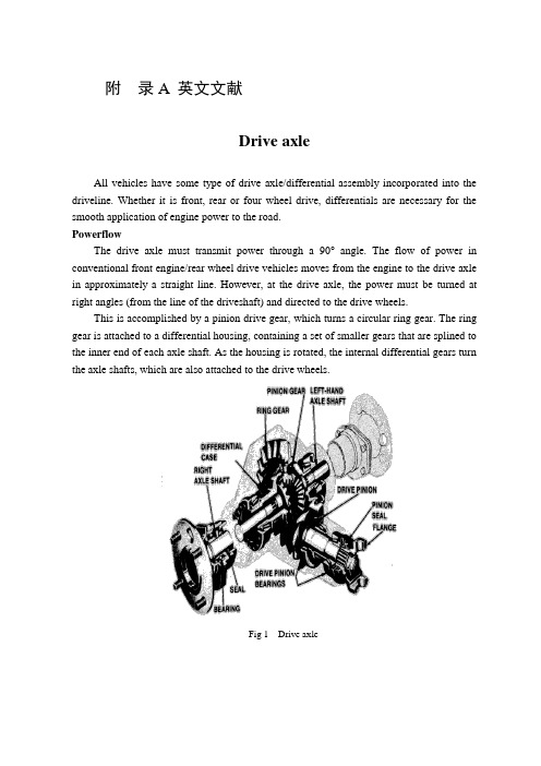
附录A 英文文献Drive axleAll vehicles have some type of drive axle/differential assembly incorporated into the driveline. Whether it is front, rear or four wheel drive, differentials are necessary for the smooth application of engine power to the road.PowerflowThe drive axle must transmit power through a 90°angle. The flow of power in conventional front engine/rear wheel drive vehicles moves from the engine to the drive axle in approximately a straight line. However, at the drive axle, the power must be turned at right angles (from the line of the driveshaft) and directed to the drive wheels.This is accomplished by a pinion drive gear,which turns a circular ring gear. The ring gear is attached to a differential housing, containing a set of smaller gears that are splined to the inner end of each axle shaft. As the housing is rotated, the internal differential gears turn the axle shafts, which are also attached to the drive wheels.Fig 1 Drive axleRear-wheel driveRear-wheel-drive vehicles are mostly trucks, very large sedans and many sports car and coupe models. The typical rear wheel drive vehicle uses a front mounted engine and transmission assemblies with a driveshaft coupling the transmission to the rear drive axle. Drive in through the layout of the bridge, the bridge drive shaft arranged vertically in the same vertical plane, and not the drive axle shaft, respectively, in their own sub-actuator with a direct connection, but the actuator is located at the front or the back of the adjacent shaft of the two bridges is arranged in series. Vehicle before and after the two ends of the driving force of the drive axle, is the sub-actuator and the transmission through the middle of the bridge. The advantage is not only a reduction of the number of drive shaft, and raise the driving axle of the common parts of each other, and to simplify the structure, reduces the volume and quality.Some vehicles do not follow this typical example. Such as the older Porsche or Volkswagen vehicles which were rear engine, rear drive. These vehicles use a rear mounted transaxle with halfshafts connected to the drive wheels. Also, some vehicles were produced with a front engine, rear transaxle setup with a driveshaft connecting the engine to the transaxle, and halfshafts linking the transaxle to the drive wheels.Differential operationIn order to remove the wheel around in the kinematics due to the lack of co-ordination about the wheel diameter arising from a different or the same rolling radius of wheel travel required, inter-wheel motor vehicles are equipped with about differential, the latter to ensure that the car driver Bridge on both sides of the wheel when in range with a trip to the characteristics of rotating at different speeds to meet the requirements of the vehicle kinematics.The accompanying illustration has been provided to help understand how this occurs.1.The drive pinion, which is turned by the driveshaft, turns the ring gear.2.The ring gear, which is attached to the differential case, turns the case.3.The pinion shaft, located in a bore in the differential case, is at right angles to the axle shafts and turns with the case.4.The differential pinion (drive) gears are mounted on the pinion shaft and rotate with the shaft .5.Differential side gears (driven gears) are meshed with the pinion gears and turn with the differential housing and ring gear as a unit.6.The side gears are splined to the inner ends of the axle shafts and rotate the shafts as the housing turns.7.When both wheels have equal traction, the pinion gears do not rotate on the pinion shaft, since the input force of the pinion gears is divided equally between the two side gears.8.When it is necessary to turn a corner, the differential gearing becomes effective and allows the axle shafts to rotate at different speeds .Open-wheel differential on each general use the same amount of torque. To determine the size of the wheel torque to bear two factors: equipment and friction. In dry conditions, when a lot of friction, the wheel bearing torque by engine size and gear restrictions are hours in the friction (such as driving on ice), is restricted to a maximum torque, so that vehicles will not spin round. So even if the car can produce more torque, but also need to have sufficient traction to transfer torque to the ground. If you increase the throttle after the wheels slip, it will only make the wheels spin faster.Limited-slip and locking differential operationFig 5 Limited-slip differentialDifferential settlement of a car in the uneven road surface and steering wheel-driven speed at about the different requirements; but is followed by the existence of differential in the side car wheel skid can not be effective when the power transmission, that is, the wheel slip can not produce the driving force, rather than spin the wheel and does not have enough torque. Good non-slip differential settlement of the car wheels skid on the side of the power transmission when the issue, that is, locking differential, so that no longer serve a useful differential right and left sides of the wheel can be the same torque.Limited-slip and locking differential operation can be divided into two major categories:(1) mandatory locking type in ordinary differential locking enforcement agencies to increase, when the side of the wheel skid occurs, the driver can be electric, pneumatic or mechanical means to manipulate the locking body meshing sets of DIP Shell will be with the axle differential lock into one, thus the temporary loss of differential role. Relatively simple structure in this way, but it must be operated by the driver, and good roads to stop locking and restore the role of differential.(2) self-locking differential installed in the oil viscosity or friction clutch coupling, when the side of the wheel skid occurs when both sides of the axle speed difference there, coupling or clutch friction resistance on the automatic, to make certain the other side of the wheel drive torque and the car continued to travel. When there is no speed difference on both sides of the wheel, the frictional resistance disappeared, the role of automatic restoration of differentials. More complicated structure in this way, but do not require drivers to operate. Has been increasingly applied in the car. About non-slip differential, not only used for the differential between the wheels, but also for all-wheel drive vehicle inter-axle differential/.Gear ratioThe drive axle of a vehicle is said to have a certain axle ratio. This number (usually a whole number and a decimal fraction) is actually a comparison of the number of gear teeth on the ring gear and the pinion gear. For example, a 4.11 rear means that theoretically, there are 4.11 teeth on the ring gear for each tooth on the pinion gear or, put another way, the driveshaft must turn 4.11 times to turn the wheels once. The role of the final drive is to reduce the speed from the drive shaft, thereby increasing the torque. Lord of the reduction ratio reducer, a driving force for car performance and fuel economy have a greater impact. In general, the more reduction ratio the greater the acceleration and climbing ability, and relatively poor fuel economy. However, if it is too large, it can not play the full power of the engine to achieve the proper speed. The main reduction ratio is more Smaller ,the speed is higher, fuel economy is better, but the acceleration and climbing ability will be poor.附录B 文献翻译驱动桥所有的汽车都装有不同类型的驱动桥和差速器来驱动汽车行驶。
机械毕业设计英文外文翻译396驱动桥 - 副本
附录A 英文文献Drive AxleAll vehicles have some type of drive axle/differential assembly incorporated into the driveline. Whether it is front, rear or four wheel drive, differentials are necessary for the smooth application of engine power to the road.PowerflowThe drive axle must transmit power through a 90°angle. The flow of power in conventional front engine/rear wheel drive vehicles moves from the engine to the drive axle in approximately a straight line. However, at the drive axle, the power must be turned at right angles (from the line of the driveshaft) and directed to the drive wheels.This is accomplished by a pinion drive gear, which turns a circular ring gear. The ring gear is attached to a differential housing, containing a set of smaller gears that are splined to the inner end of each axle shaft. As the housing is rotated, the internal differential gears turn the axle shafts, which are also attached to the drive wheels.Rear-wheel driveRear-wheel-drive vehicles are mostly trucks, very large sedans and many sports car and coupe models. The typical rear wheel drive vehicle uses a front mounted engine and transmission assemblies with a driveshaft coupling the transmission to the rear drive axle. Drive in through the layout of the bridge, the bridge drive shaft arranged vertically in the same vertical plane, and not the drive axle shaft, respectively, in their own sub-actuator with a direct connection, but the actuator is located at the front or the back of the adjacent shaftof the two bridges is arranged in series. Vehicle before and after the two ends of the driving force of the drive axle, is the sub-actuator and the transmission through the middle of the bridge. The advantage is not only a reduction of the number of drive shaft, and raise the driving axle of the common parts of each other, and to simplify the structure, reduces the volume and quality.Fig 2 Rear-wheel-drive axle Some vehicles do not follow this typical example. Such as the older Porsche or Volkswagen vehicles which were rear engine, rear drive. These vehicles use a rear mounted transaxle with halfshafts connected to the drive wheels. Also, some vehicles were produced with a front engine, rear transaxle setup with a driveshaft connecting the engine to the transaxle, and halfshafts linking the transaxle to the drive wheels.Differential operationIn order to remove the wheel around in the kinematics due to the lack of co-ordination about the wheel diameter arising from a different or the same rolling radius of wheel travel required, inter-wheel motor vehicles are equipped with about differential, the latter to ensure that the car driver Bridge on both sides of the wheel when in range with a trip to the characteristics of rotating at different speeds to meet the requirements of the vehicle kinematics.Fig 3 Principle of differential The accompanying illustration has been provided to help understand how this occurs.1.The drive pinion, which is turned by the driveshaft, turns the ring gear.2.The ring gear, which is attached to the differential case, turns the case.3.The pinion shaft, located in a bore in the differential case, is at right angles to the axle shafts and turns with the case.4.The differential pinion (drive) gears are mounted on the pinion shaft and rotate with the shaft .5.Differential side gears (driven gears) are meshed with the pinion gears and turn with the differential housing and ring gear as a unit.6.The side gears are splined to the inner ends of the axle shafts and rotate the shafts as the housing turns.7.When both wheels have equal traction, the pinion gears do not rotate on the pinion shaft, since the input force of the pinion gears is divided equally between the two side gears.8.When it is necessary to turn a corner, the differential gearing becomes effective and allows the axle shafts to rotate at different speeds .Open-wheel differential on each general use the same amount of torque. To determine the size of the wheel torque to bear two factors: equipment and friction. In dry conditions, when a lot of friction, the wheel bearing torque by engine size and gear restrictions are hours in the friction (such as driving on ice), is restricted to a maximum torque, so that vehicles will not spin round. So even if the car can produce more torque, but also need to have sufficient traction to transfer torque to the ground. If you increase the throttle after the wheels slip, it will only make the wheels spin faster.Fig 4 Conventional differentialLimited-slip and locking differential operationFig 5 Limited-slip differential Differential settlement of a car in the uneven road surface and steering wheel-driven speed at about the different requirements; but is followed by the existence of differential in the side car wheel skid can not be effective when the power transmission, that is, the wheel slip can not produce the driving force, rather than spin the wheel and does not have enough torque. Good non-slip differential settlement of the car wheels skid on the side of the power transmission when the issue, that is, locking differential, so that no longer serve a useful differential right and left sides of the wheel can be thesame torque.Limited-slip and locking differential operation can be divided into two major categories:(1) mandatory locking type in ordinary differential locking enforcement agencies to increase, when the side of the wheel skid occurs, the driver can be electric, pneumatic or mechanical means to manipulate the locking body meshing sets of DIP Shell will be with the axle differential lock into one, thus the temporary loss of differential role. Relatively simple structure in this way, but it must be operated by the driver, and good roads to stop locking and restore the role of differential.(2) self-locking differential installed in the oil viscosity or friction clutch coupling, when the side of the wheel skid occurs when both sides of the axle speed difference there, coupling or clutch friction resistance on the automatic, to make certain the other side of the wheel drive torque and the car continued to travel. When there is no speed difference on both sides of the wheel, the frictional resistance disappeared, the role of automatic restoration of differentials. More complicated structure in this way, but do not require drivers to operate. Has been increasingly applied in the car. About non-slip differential, not only used for the differential between the wheels, but also for all-wheel drive vehicle inter-axle differential/.Gear ratioThe drive axle of a vehicle is said to have a certain axle ratio. This number (usually a whole number and a decimal fraction) is actually a comparison of the number of gear teeth on the ring gear and the pinion gear. For example, a 4.11 rear means that theoretically, there are 4.11 teeth on the ring gear for each tooth on the pinion gear or, put another way, the driveshaft must turn 4.11 times to turn the wheels once. The role of the final drive is to reduce the speed from the drive shaft, thereby increasing the torque. Lord of the reduction ratio reducer, a driving force for car performance and fueleconomy have a greater impact. In general, the more reduction ratio the greater the acceleration and climbing ability, and relatively poor fuel economy. However, if it is too large, it can not play the full power of the engine to achieve the proper speed. The main reduction ratio is more Smaller ,the speed is higher, fuel economy is better, but the acceleration and climbing ability will be poor.附录B 文献翻译驱动桥所有的汽车都装有不同类型的驱动桥和差速器来驱动汽车行驶。
汽车驱动桥常见故障分析及维修方法外文文献翻译、中英文翻译、外文翻译
附录Car driver bridge just common failure analysis and repair methods Motor reducer main function is to increase the input torque, lower speed, and will accept the transfer of power to change the direction of differential. Disassembly in the maintenance process, the main reducer assembly and adjustment of the quality of the good or bad, a direct impact on the main reducer of the state of technology and the main gear reducer, vice life. Must be in accordance with technical requirements and methods to ensure that the assembly quality and accuracy of the adjustment. Reducer in the main assembly in the process of adjustment, including the main owners, driven bevel gear bearing pre-adjustments, the main, driven cone-prints and meshing gears meshing space adjustments, and so on. Reducer in the main assembly adjustment, the adjustment in order to ensure the quality of assembly, must abide by the rules as follows: First, the first adjustment of the pre-bearings, and then adjust the gear mesh, vice-prints, the final adjustment of the meshing gears, deputy space. Secondly, the main, driven gear bearing cone of pre-degree must be provided for in the original methods and numerical check and adjust the main reducer in the process of adjustment, bearing the pre-degree change may not always be in line with the original Provides value. Third, to ensure the engagement of qualified prints on the premise of the adjustment of meshing gears, deputy space. Meshing and mesh-prints of the changes in the amount of space must be in compliance with technical requirements, otherwise it is necessary to replace the pair in pairs. Fourth, the adjustment process, such as bevel gear, bevel gear Aoli Kang and hypoid bevel gear, often moving to take the initiative to adjust the bevel gear mesh prints, driven by mobile bevel gear meshing space adjustments. The high-arc bevel gear Gleason bevel gear meshing and mesh-prints of the gap adjustment method is not special.Bearing reducer main pre-adjustments in order to remove the main, driven bevel gear shaft bearing the extra space axial and radial clearance, and reducer installed in the main, driven bevel gear shaft bearings, it should be a certain The pre-compression, and part of the balance before and after the axial load bearing. This willmake the main, driven bevel gear at work to maintain the right mesh, and can pre-and post-bearings to obtain a more uniform wear. First of all, take the initiative to adjust the bevel gear bearing the pre-, pre-adjustment of their degrees in two ways: The first method is through changes in the gasket to adjust to adjust. Adjust the location of gaskets, and some separation between the two sets of bearings, some shaft in the shoulder, some in the back of the main reducer. Adjusted increase in the pads, reducing the pre-degree; pads to reduce the adjustment, increased pre-degrees. The second method is to use an alternate set of flexibility to adjust it by the installation, according to the provisions of torque tightening nut penetration margin of the fixed disk, so that every other set of elastic deformation resulting from the initiative to ensure the bevel gear bearing the pre-degrees. Next, adjust the bevel gear follower of the pre-degree bearing. According to the driver of the bridge structure is divided into two different ways: the first is a single-stage reducer, which is driven bevel gear differential bearing bearings, driven adjustment bevel gear bearing pre-degree differential bearing adjustment is pre - Tight, adjust the differential bearing on both sides of the nut adjustment to achieve. Adjustments on both sides of the nut tightened, pre-degree increase; on both sides of the adjustment screw pine nut, pre-degree decrease. The second is a two-stage reducer, the bevel gear driven secondary and take the initiative to slow down the cylindrical gear with a fixed axis, with both ends of the bearing shell on the main reducer. Adjust the location of gaskets in the two bearings between the shell and cover. Adjusted increase in the pads, reducing the pre-degree; pads to reduce the adjustment, increased pre-degrees. Second, the main, driven bevel gears meshing tooth prints and the adjustment of the main side of the gap, driven bevel gears meshing side of the gap-tooth-prints and adjustment: the main, be driven bevel gear teeth along the direction of the long exposure, and its location in the control gear The little-central bias, the small end-to-end from the Ministry of 2 ~ 7mm, traces of contact with the length of not less than 50% of the long teeth, tooth direction of the high-contact-prints should be not less than 50% of the high-gear, the general should be from the addendum 0 . 80 ~ 1.60mm; side of the tooth gap to 0. 15 ~ 0. 50mm, but each of the bevel gears meshingVice change in the amount of space no larger than 0.15mm. When the owners, driven bevel gears meshing side of the gap-tooth-prints and do not meet the requirements should be adjusted in accordance with the following method to simplify the formula is: "Progressive", that is, when the mating preference-prints big-time, move from gear to gear shift Near; at this time if the tooth side of the gap is too small, will take the initiative to move out of gear. "From a small", that is, when the mating preference-prints little-time, move from gear to gear the initiative away; at this time if the tooth side of the gap is too large, the initiative will be moved closer to the gear inside. "Lord jacking", that is, when the mating preference-prints addendum, the initiative will be moved closer to the driven gear to gear; at this time if the tooth side of the gap is too small, will be driven out of gear away. "The main root out", that is, when the mating preference-prints root, it will take the initiative to gear since moving away gear; at this time if the tooth side of the gap is too large, driven gear will be moved closer to the inside.In the motor-driven mechanical automotive power train, drive power train bridge at the end of their basic function is to increase the transmission shaft or transmission came directly from the torque, torque will be allocated to the left and right wheel drive with Vehicle kinematics required by the differential function; at the same time, drivers also have to face the role of the bridge on the road or inside the frame and between the vertical, horizontal and vertical force. Therefore, vehicle drive axle should have the following functions: to ensure that the right has a reduction ratio, so that the car has the best power and fuel economy; differential with the role to ensure that the vehicle or to the uneven roads, tires do not have a Waterloo is delayed; have greater ground clearance in order to ensure the adoption of good; as much as possible to reduce weight in order to reduce vehicle weight; gear transmission and other mechanical work in a smooth, noise-free. Driver function as the bridge complex, so a higher failure rate. Its main fault: the early damage to the main reducer, made bridge-driven sound, heating and oil and so on.Bridge driver were the causes of the different and various fault is not the formation of a single isolated, but interrelated. If afailure occurred in a timely manner is not ruled out, it is easy to induce another failure to form a chain reaction. If the gap is too small mesh gear, it would drive axle fever, and it will lead to fat drive axle ring, but also the main cause of early damage to the reducer. Reducer is the main driver bridge in the heart of its early damage will seriously affect the life of the drive axle. Early in the form of its damage are: Vice-gear early wear, tooth fracture, early damage to the gear bearings and so on. Meshing gears are too small or too large gap caused by wear and tear in the early gears. Bearing the pre-force is too large or too small. Preload is too large, the impact on the efficiency of transmission so that the bearings overheat and shorten the life span; Preload over an hour to make the situation worse meshing of gears, contact stress increases, leading to a pair of early wear and tear. Not add gear oil requirements. Main reducer to be added as required gear oil in order to guarantee the normal lubrication of the gear, otherwise, in a very short car mileage, the tooth will be due to poor lubrication caused by pitting, and a sharp bond wear. Driven gear as a result of the adjustment locking nut loose and have a shift. Adjust the nut loose, causing a passive gear shift, the meshing gap change gear, Deputy Ambassador of early wear and tear.Common faults:1. Tooth fracture. Meshing gears too much space. When the gear mesh in time to adjust without too much space, so that the owners, driven gear engagement in the process of impact, making gear fault.2. Differential gear bearings or bearing damage. Bearing damage, roller out in the main reducer, the gear will be damaged.3. Driven gear differential with the loose bolt connections, and off, also damaged gear.4. Severely overloaded vehicle, so that the bearing load, making it lower life expectancy. Overloaded vehicle traveling through uneven pavement, gears and bearings, etc. impact on the load in a row and the role of the early damage occurred.In short, the judge ruled out and drive axle failure, it is necessary to analyze specific issues. In general, improper use, improper assembly adjustment, the quality of the parts itself is a question which drives the root causes of bridge failure. The fault has produced a number of reasons, or one; at the same time, adjustmentof the assembly, such as using incompatible with a drive axle that could cause a variety of failures.汽车驱动桥常见故障分析及维修方法汽车主减速器的功用是将输入的转矩增大,转速降低,并将接受的动力传递方向改变后传给差速器。
汽车驱动桥设计外文文献翻译、中英文翻译、外文翻译

AppendixChina in the first half of 2008 about 93 million trucks accumulative total sales of cars, vans 61 million vehicles, year-on-year growth of 20.2%, visible light car in commercial car production has a large proportion. And driving axle is very important in the vehicle driving axle is the important car auto bearing assembly, auto frame and integral by suspension of body vertical force, to lead the longitudinal forces, transverse force and torque, and impact load; Driving axle also delivers the transmission, the maximum torque reaction is under.Automobile driving axle structure and design parameters in addition to the reliability of the automobile and durability have important influence on the outside, also for the automobile driving performance such as power, economy, smooth, through sex, mobility Automobile driving axle design involves the mechanical parts and components is widely to these varieties, spare parts, components and assemblies manufacturing also almost want to design to all modern machinery manufacturing process, design a simple structure, reliable operation and low cost, can greatly reduce the drive axle of the total cost of the vehicle production, promote economic development, and car to drive through the car studying and designing practice, can better learning and mastery of the modern car design and mechanical design of the comprehensive knowledge and skills, and the overall thinking and operation skill check, drawing, is the very important link, so ontology of a structure design of fine vans axles has certain Automobile driving axle is one of the main parts car, its basic function is to enlarge the shaft or by the torque transmission spread, then torque distribution to drive wheels, and make about driving wheel has about vehicle movement required differential function; Axles in the end of powertrain system, choose proper Lord slowdown, ensure cars than with sufficient ground clearance is achieved, gear and other transmission job need to ensure smooth are the parameters, and even bear effect on the pavement drive axle and frame or carrying body vertical force, the lead between transverse and longitudinal force and torque force. Driving axle quality, performance will have a direct impact on the vehicle's safety, economy, comfort and reliability. After the car driving axle design can make the students' comprehensive by using their This thesis research aims to overall matching car by driving axle Lord finish design of gear reducer, differential component such as type of design and calculation, and complete checking and comprehensive design single main reducer, then the batch Through the design of the vehicle driving axle should also master the understanding, including each component interaction between the body and the electricalsystem, the influence and cooperate to drive axle of the process and therefore more familiar with vehicle mastery. That in the future the production and living effectly use.附录我国2008年上半年货车累计销售约93万辆,其中轻型货车61万辆,同比增长20.2%,可见轻型汽车在商用汽车生产中占有很大的比重。
中英文文献翻译-驱动桥设计与分析的理论研究现状

附录A 外文文献The present situation of theory research on Drive axle design and analysis With the development of testing technology and improved driving axle in the design process to test the introduction of new technology and a variety of test equipment dedicated to carry out scientific experiments, all aspects of product structure, performance and strength of parts and components, life testing At the same time, extensive use of modern mathematical physics analysis, and assembly of products, parts and components to carry out a full technical analysis, research, and thus drive the development of bridge design theory to scientific experiments and technical analysis is based on the stage.(1) Computer Supported drive axle design and analysis of the theoretical innovation:Computer in the engineering design of the popularization and application, so that the bridge design theory-driven and technology leap in the development of completely different design process. Drive axle structure parameters and the optimization of performance parameters such as selection and matching, the intensity of components accounting and life prediction, simulation of the relevant products or simulation analysis of the art form that is more so on the choice of design and shape, design drawings Drawing will be conducted on the computer. The use of computer tools for analysis, because of its fast computing and large data capacity, we can use more accurate mathematical model of multi-degree of freedom to simulate the driving axle of the campaign in a variety of conditions, the use of modern advanced mathematics methods of analysis, can be obtained more accurate results, which analyzed for a variety of programs designed to work creatively to provide a great convenience. At present, due to the external computer equipment and the achievements of human-computer links, can be the computer's rapid calculation and logic to determine the capacity, high-capacity data storage and efficient data-processing capacity, the calculation results of dynamic image display function and creativity thinking ability and experience, the realization of human-computer dialogue-style semi-automatic design, or product design expert systems, design automation. The design process can be computer-related products on a large amount of data, data retrieval, on the design of the design of high-speed computing, computer screen displays graphics and design calculations; designers can also be used up pen and direct man-machine dialogue language graphic changes to achieve the best design options, and then by computer graphics equipment line drawings drawn products. This use of computers and external devices product design methods, collectively referred to as computer-aided design. CAD and CAM will be the future into CADMAT system will show the usefulness of its huge.(2) basic studies to support the drive axle design and analysis of the theoretical innovation:With the computer design of drive axle in the popularization and application, a number of modern methods of mathematical physics and the basis for new theoretical achievements in the automotive design has become more widely used. The design of modern drive axle, in addition to traditional methods, computer-aided design methods, but also the introduction of the most optimal design, reliability, design, finite element analysis of computer simulation or simulation analysis, modal analysis and other modern design methods and analytical tools. Bridge design and analysis of drive to achieve the current high level of theory, especially the past three decades is more than a century of basic science, applied technology, materials and manufacturing processes result of continuous development and progress as well as design, production and use of long-term accumulation of experience. It is based on the production of large-scale practice, the basis of the theory as a guide to reflect the achievements of contemporary science and technology-driven bridge design software and hardware as a means to meet the needs of society for the purpose, through the use of materials, technology, equipment, tools, testing equipment, test the technical and business achievements in the field of management, continuous development and progress.(3) reverse engineering theory and methods widely used:Driving axle in the field of automated manufacturing, and often involve an enormous amount of complex design and manufacturing and testing surface. Under normal circumstances, first of all applications on the computer computer-aided design and manufacturing technology for the design of product model, and then generate code for processing. With the traditional processing model, compared to reverse engineering a CAD model of characterization of non-existing methods of product design, but through a variety of ways from the physical model was taken from the data re-engineering development models of a product amend. Drive the design and manufacture of axle housing is a very typical reverse engineering methods.(4) the application of rapid prototyping technology :Product innovation is designed to give full play to the designer's creative imagination, using the technical knowledge and skills to carry out the innovative ideas that the principle of a practice, its aim is to creatively design a rich and advanced new products. In the development of traditional design, the process is divided into program design, technical design, process design and product manufacturing. With the development of information technology, product design and development of the scope of the content from the traditional extended to product planning, manufacturing, testing, testing , marketing, as well as the whole process of recovery. Traditional design, the extension of the product development cycle. Rapid prototyping technology is the complete CAD model solid model layer by layermanufacturing technology, rapid prototyping technology to rid itself of the traditional processing methods, the growth of a new processing method to the complex three-dimensional processing is decomposed into a simple combination of two-dimensional processing. Therefore it does not need the use of traditional machine tools and processing tool, and only 10% of traditional processing methods of a 30% and 20% of the working hours of a 30% of the cost of products will be able to directly create and mold samples. Product innovation in the design and development application of rapid prototyping technology, with modern high-tech tools and technology to transform traditional methods of product design and development, to promote design innovation, product innovation, process innovation and management innovation to form a digital, virtual and intelligent , integrated in order to bring about a revolution in product design and development.(5) the application of concurrent engineering to product management and development:Drive Axle Industries has launched a worldwide competition designed to shorten a new product development time, reduce costs, improve quality, increase market competitiveness, manufacturers are increasingly becoming the most important issue to consider. Concurrent Engineering as a modern, advanced product design and development model to address these problems is a good way for countries to the automotive industry has been used. The so-called concurrent engineering, is the integrated, concurrent design of products and related processes of systems engineering, it takes from concept to product design, shape design, manufacture, use, maintenance of the entire process until the end of life of all the relevant factors that can solve the out of touch the design and manufacturing process design changes caused by frequent and long development time, cost of Higher contradictions can be designed to maximize the quality and development efficiency, and increase market competitiveness. Concurrent engineering, the key is the process of the product and its associated parallel implementation of integrated design, manufacturing and assembly-oriented design is an important aspect of concurrent engineering in product development throughout the entire process of design is the key. Innate quality of the product design decisions. Statistics show that products, including raw materials, manufacture, use, maintenance and other costs that 70% of the generalized cost is a decision from the design stage. The objectives of concurrent engineering is as much as possible early in the design stage on the introduction of the manufacture and assembly of the binding process, such as material selection, manufacturing processes, and assembly of such constraints, design changes to make as much as possible in the early stage of product development, and from manufacturing to assembly to reduce the occurrence of adverse situations, when to make a successful product design, product development to avoid the late change in design d ue to the enormous waste, which on the drive axle design and subAnalysis of the objectives of the theory put forward more demands.附录B外文文献的中文翻译驱动桥设计与分析的理论研究现状随着测试技术的发展与完善,在驱动桥设计过程中引进新的测试技术和各种专用的试验设备,进行科学实验,从各方面对产品的结构、性能和零部件的强度、寿命进行测试,同时广泛采用近代数学物理分析方法,对产品及其总成、零部件进行全面的技术分析、研究,这样就使驱动桥设计理论发展到以科学实验和技术分析为基础的阶段。
中英文文献翻译-驱动桥概述

附录 1在汽车行驶过程中,驱动桥承受着繁重而复杂的载荷,它的传动件(齿轮及半轴等)要传递传动系中的最大扭矩;它的承载件(桥壳)支承着汽车汽车荷重,承载着作用于路面与车架或车厢之间的垂向、纵向和横向的静、动(冲击)载荷,以及反作用力矩或制动力矩等。
在这些载荷的作用下,驱动桥必须必须保持有足够的强度、刚度,足够的寿命,以及满意的其他性能(例如我噪音)等。
为此,驱动桥总成及其主要的零、部件,必须经受严格的实验。
通常,驱动桥总成及其主要零、部件一样,需装车后进行整车道路试验,和在室内进行台架实验,以考验驱动桥总成及其零、部件在整车上的适应性,以及其它的可能性、耐久性和其它性能。
因此,我国许多汽车制造厂都设有道路试验室和总成及零部件实验室,而目前在国外,不论是综合性的汽车工业公司,还是生产汽车总成的专业公司,都设有规模较大的实验,研究中心,负责有关汽车的各种实验、研究和技术开发。
有的还附设有相当规模的汽车试验场或专用实验跑道等。
附录2In automobile driving process, driving axle under the heavy and complicated load, its transmission parts (gears and half axle, etc.) to pass the transmission of the maximum torque, It's ChengZaiJian (bridge shell) supporting the car automobile load, bearing the effect on the pavement and frame or carraige between vertical and lateral and longitudinal impact of dynamic and static load, and (the) reaction torque or braking torque, etc. In these load, under the action of driving axle must must maintain a sufficient strength, stiffness, enough life, and satisfactory other properties (such as I noise), etc. Therefore, driving axle assembly and the main parts and components, must undergo strict experiments.Usually, driving axle assembly and its main parts and components, need to load the same after the road test, and the vehicle in indoor experiments to test bench and its driving axle assembly parts and components in the vehicle on the adaptation and the other possibilities, durability and other properties. Therefore, our country many automobile factory is equipped with the road test and assemblies and components laboratory, and at present in a foreign country, whether comprehensive vehicle industry company, or production automobile assembly specialized company, is equipped with larger scale of experiment, the research center, be responsible for relevant car various experimental, research and development of the technology. Some still laden with the large scale of automobile farms or special experimental runway.。
中英文文献翻译-驱动桥
中英文文献翻译-驱动桥AppendixChina in the first half of 2008 about 93 million trucks accumulative total sales of cars, vans 61 million vehicles, year-on-year growth of 20.2%, visible light car in commercial car production has a large proportion. And driving axle is very important in the vehicle driving axle is the important car auto bearing assembly, auto frame and integral by suspension of body vertical force, to lead the longitudinal forces, transverse force and torque, and impact load; Driving axle also delivers the transmission, the maximum torque reaction is under.Automobile driving axle structure and design parameters in addition to the reliability of the automobile and durability have important influence on the outside, also for the automobile driving performance such as power, economy, smooth, through sex, mobility Automobile driving axle design involves the mechanical parts and components is widely to these varieties, spare parts, components and assemblies manufacturing also almost want to design to all modern machinery manufacturing process, design a simple structure, reliable operation and low cost, can greatly reduce the drive axle of the total cost of the vehicle production, promote economic development, and car to drive through the car studying and designing practice, can better learning and mastery of the modern car design and mechanical design of the comprehensive knowledge and skills, and the overall thinking and operation skill check, drawing, is the very important link, so ontology of a structure design of fine vans axles has certain Automobile driving axle is one of the main parts car, its basic function is to enlarge the shaft or by the torquetransmission spread, then torque distribution to drive wheels, and make about driving wheel has about vehicle movement required differential function; Axles in the end of powertrain system, choose proper Lord slowdown, ensure cars than with sufficient ground clearance is achieved, gear and other transmission job need to ensure smooth are the parameters, and even bear effect on the pavement drive axle and frame or carrying body vertical force, the lead between transverse and longitudinal force and torque force. Driving axle quality, performance will have a direct impact on the vehicle's safety, economy, comfort and reliability. After the car driving axle design can make the students' comprehensive by using their This thesis research aims to overall matching car by driving axle Lord finish design of gear reducer, differential component such as type of design and calculation, and complete checking and comprehensive design single main reducer, then the batch Through the design of the vehicle driving axle should also master the understanding, including each component interaction between the body and the electricalsystem, the influence and cooperate to drive axle of the process and therefore more familiar with vehicle mastery. That in the future the production and living effectly use.附录我国2008年上半年货车累计销售约93万辆,其中轻型货车61万辆,同比增长20.2%,可见轻型汽车在商用汽车生产中占有很大的比重。
机械毕业设计英文外文翻译398驱动桥_(2)

附录 A 英文文献Drive axleAll vehicles have some type of drive axle/differential assembly incorporated into the driveline. Whether it is front, rear or four wheel drive, differentials are necessary for the smooth application of engine power to the road.PowerflowThe drive axle must transmit power through a 90 angle. The°flow of power in conventional front engine/rear wheel drive vehicles moves from the engine to the drive axle in approximately a straight line. However, at the drive axle, the power must be turned at right angles (from the line of the driveshaft) and directed to the drive wheels.This is accomplished by a pinion drive gear, which turns a circular ring gear. The ring gear is attached to a differential housing, containing a set of smaller gears that are splined to the inner end of each axle shaft. As the housing is rotated, the internal differential gears turn the axle shafts, which are also attached to the drive wheels.Rear-wheel driveRear-wheel-drive vehicles are mostly trucks, very large seda ns and many sports car and coupe models. The typical rear wheel drive vehicle uses a front mounted engine and transmission assemblies with adriveshaft coupling the transmission to the rear drive axle. Drive in through the layout of the bridge, the bridge drive shaft arranged vertically in thesame vertical plane, and not the drive axle shaft, respectively, i n their own sub-actuator with a direct conn ecti on, but the actuator is located at the front or the back of the adjace nt shaft of the two bridges is arranged in series. Vehicle before and after the two ends of the driv ing force of thedrive axle, is the sub-actuator and the tran smissi on through the middle of the bridge. The adva ntage is not only a reduction of the number of drive shaft, and raise the driving axle of the common parts of each other, and to simplify the structure, reduces the volume and quality.Some vehicles do not follow this typical example. Such as the olderPorsche or Volkswagen vehicles which were rear engine, rear drive. RING GEAP£ 1■ ■■ BEARING RIGHT AXLESHAFTPINION GEAR LER-HA^DI AXLE SHAHDRIVE HNMN\ DRIVE PINION,二omRENTIAL ‘CASE 亠 /:Fig 1 Drive axleThese vehicles use a rear mounted transaxle with halfshafts connected to the drive wheels. Also, some vehicles were produced with a front engine, rear transaxle setup with a driveshaft connecting the engine to the transaxle, and halfshafts linking the transaxle to the drive wheels. Differential operationIn order to remove the wheel around in the kinematics due to the lack of co-ordination about the wheel diameter arising from a different or the same rolling radius of wheel travel required, inter-wheel motor vehicles are equipped with about differential, the latter to ensure that the car driver Bridge on both sides of the wheel when in range with a trip to the characteristics of rotating at different speeds to meet the requirements of the vehicle kinematics.The accompanying illustration has been provided to help understand how this occurs.1. The drive pinion, which is turned by the driveshaft, turns the ring gear.2. The ring gear, which is attached to the differential case, turns the case.3. The pinion shaft, located in a bore in the differential case, is at right angles to the axle shafts and turns with the case.4. The differential pinion (drive) gears are mounted on the pinion shaft and rotate with the shaft .5. Differential side gears (driven gears) are meshed with the pinion gears and turn with the differential housing and ring gear as a unit.6. The side gears are splined to the inner ends of the axle shafts and rotate the shafts as the housing turns.7. When both wheels have equal traction, the pinion gears do not rotate on the pinion shaft, since the input force of the pinion gears isdivided equally between the two side gears.8. When it is necessary to turn a corner, the differential gearing becomes effective and allows the axle shafts to rotate at different speeds .Open-wheel differential on each general use the same amount of torque. To determine the size of the wheel torque to bear two factors: equipment and friction. In dry conditions, when a lot of friction, the wheel bearing torque by engine size and gear restrictions are hours in the friction (such as driving on ice), is restricted to a maximum torque, so that vehicles will not spin round. So even if the car can produce more torque, but also need to have sufficient traction to transfer torque to the ground. If you increase the throttle after the wheels slip, it will only make the wheels spin faster.Limited-slip and locking differential operationDifferential settlement of a car in the uneven road surface and steeringwheel-drive n speed at about the differe nt requireme nts; but is followed by the existenee of differential in the side car wheel skid can not beeffective when the power transmission, that is, the wheel slip can notproduce the driv ing force, rather tha n spin the wheel and does not have eno ugh torque. Good non-slip differe ntial settleme nt of the car wheels skid on the side of the power transmission when the issue, that is, lock ing differe ntial, so that no Ion ger serve a useful differe ntial right and leftsides of the wheel can be the same torque.Limited-slip and locking differential operation can be divided into twomajor categories :(1) mandatory locking type in ordinary differential lockingen forceme nt age ncies to in crease, whe n the side of the wheel skidoccurs, the driver can be electric, pneumatic or mechanical means tomanipulate the locking body meshing sets of DIP Shell will be with theaxle differe ntial lock into one, thus the temporary loss of differe ntial role. Relatively simple structure in this way, but it must be operated by the driver, and good roads to stop locking and restore the role of differential.a tie shaftpinion shaftdiffarartial \畑9"哼differenld ” pinionFig 5 Limited-slip differential(2) self-locking differential installed in the oil viscosity or friction clutch coupling, when the side of the wheel skid occurs when both sides of the axle speed difference there, coupling or clutch friction resistance on the automatic, to make certain the other side of the wheel drive torque and the car continued to travel. When there is no speed difference on both sides of the wheel, the frictional resistance disappeared, the role of automatic restoration of differentials. More complicated structure in this way, but do not require drivers to operate. Has been increasingly applied in the car. About non-slip differential, not only used for the differential between the wheels, but also for all-wheel drive vehicle inter-axle differential/.Gear ratioThe drive axle of a vehicle is said to have a certain axle ratio. This number (usually a whole number and a decimal fraction) is actually a comparison of the number of gear teeth on the ring gear and the pinion gear. For example, a 4.11 rear means that theoretically, there are 4.11 teeth on the ring gear for each tooth on the pinion gear or, put another way, the driveshaft must turn 4.11 times to turn the wheels once. The role of the final drive is to reduce the speed from the drive shaft, thereby increasing the torque. Lord of the reduction ratio reducer, a driving force for car performance and fuel economy have a greater impact. In general, the more reduction ratio the greater the acceleration and climbing ability, and relatively poor fuel economy. However, if it is too large, it can not play the full power of the engine to achieve the proper speed. The main reduction ratio is more Smaller ,the speed is higher, fuel economy is better, but the acceleration and climbing ability will be poor.附录 B 文献翻译驱动桥所有的汽车都装有不同类型的驱动桥和差速器来驱动汽车行驶。
汽车车辆类驱动桥的设计外文文献翻译、外文翻译、中英文翻译
汽车车辆类驱动桥的设计外文文献翻译、外文翻译、中英文翻译XXX毕业设计(论文)附录IDrive axle powertrain at the end of their basic function is to increase XXX, and a reasonable distribution ofpower to the left and right wheel, XXX between the vertical, XXX the main drive axle reducer, differential, XXX.The design of the Drive axle:Drive axle XXX:1. Select the main reduction ratio should be able to ensure the car has the XXX.2. Smaller size, XXX clearance.3. Gear and other pieces of the work of a smooth transmission,and small noise.4. In a variety of speed and load with a high transmission efficiency.5. XXX, XXX of small, especially under the mass-spring should be as small as possible XXX.6. And suspension movement-oriented coordination of steering drive axle, XXX.7. The structure of simple, good processing, manufacturing, easy disassembly, XXX.Drive axle classification-1-XXX毕业设计(论文)XXX-style-type with two broad categories.1. Non-disconnect-type drive axleNon-disconnect-type drive axle also known as integrated drive axle, the axlecasing and the XXX with shell shell and connected to a rigid beam,XXX with the frame components. It consists of drive axle housing 1, the mainreducer, differential and axle components.2. disconnect-type drive axle.Drive the use of independent suspension bridge, that is the main XXX vehicle chassis, on both sides of the axle and wheel in the horizontalplane as opposed to relative movement of the body is referred to as drive off thebridge.In order to match with independent suspension, the main reducer shell fixed at theframe (or body), the drive axle housing sub connected through the hinge, or inaddition to the main reducer shell outside the shell is no longer driven to other partsof the bridge. Wheel in order to meet the needs of independent jump up and down,between the differential and the wheel axle of the above connection between the useof universal joints.Drive axle componentsXXX by the main bridge reducer, differential, XXX.1. Main reducer assemblyUsed to change the main drive reducer general direction, to reduce speed andincrease torque, and ensure there is sufficient car drivers and the appropriate speed-2-XXX毕业设计(论文)skin. More types of the main reducer, a single-stage, dual-class, two-speed, such asWheel Speed Reducer.1) single-stage main reducerXXX of the devices, called single-stagereducer. Its structure is simple, light weight, such as Dongfeng BQl090 type light andmedium-sized trucks on a wide range of applications.2) two-stage main reducerLarger number of heavy-duty trucks, require a larger reduction ratio, the main useof a single-stage reducer drive, moving from gear to be XXX drive axle of the ground clearance, so the use of two XXX-stage reducer. There are two sets of two-stage reduction gear reducer, XXX.XXX, slowdown the first-class pair of XXX. Gears 2 is XXX.XXX, gear driven rotary driven round silver, XXX second stage XXX, and drive gear driven rotating cylinder, asecond-class speed. Due to the driven XXX, so that when the driven gear rotating cylinder, through the differentialand drive axle that is, the rotation of the wheels.2. DifferentialDifferential is designed to connect the axle around, on both sides of the XXX at the same time. To ensure the normal -3-XXX毕业设计(论文)XXX. Some multi-bridge-driven cars, in the sub-XXX, XXX role is to turn in the car or on uneven road surface,so that drive wheels before and after the XXX.At present, China-made cars and other types of vehicles in the basic use XXX, axle gears, planetary gear axis (cross-axis or a direct-axis) XXX of the shell and so on.XXX planet gears, planetary gearshaft, the two cone axle differential gear, and about the composition of the shell andso on.3.Auto semi-axleXXX, drive wheels spin,promote the solid axle car. As a result of the installation of wheel structure, and theforces of the axle are also different. Therefore, divided into full-floating axle,semi-floating, 3 / 4, three types of floating.1) full-floating axleGenerally large and medium-sized used car floating the whole structure. Axle withthe inner end of the XXX for the text on the axle casing. Rearaxle shell casing pressure and one pair to form the drive XXX forms, axle and axle housing no direct link so that only bear the drive-4-XXX毕业设计(论文)XXX, the axle referred to as "full-floating" axle.The so-called "floating", XXX axle.Full-floating axle, the outer end flange plate for one made with the axis. But there arealso a number of trucks to make a separate flange parts, and by XXX, at both ends of the axle spline, you can use for the first.2) semi-floating axleSemi-floating axle with the inner end of the same floating, not subject to XXX from direct client support through a bearing in the axle of theinner shell. This approach will support the outer end XXX,this short-XXX, but also to sustain the local moment, itis known as the semi-floating axle. This structure is mainly used in small passengercars.License Hongqi CA7560 icon for the type of drive axle XXX end of its moment, out client has to bear all the moment, so called semi-floatingbearing.3) 3 / 4 floating axle3 /4 XXX-floating and full floating between. At present the application of this XXX, M20vehicles.4. Automobile axle housing:1) the overall shell-style bridgeBridge shell due to the XXX, XXX, adjustment and maintenance, and XXX-5-XXX毕业设计(论文)housing due to different manufacturing methods XXX, pressed into the middle of casting XXX,XXX.2) sub-type drive axle housingSub-type XXX sections, XXX and processing easier.-6-XXX毕业设计(论文)附录II驱动桥处于动力传动系的末了,其根本功用是增大由传动轴或变速器传来的转矩,并将动力公道的分派给左、右驱动轮,别的还蒙受感化于路面和车架或车身之间的垂竖立、纵向力和横向力。
中英文文献翻译-驱动桥和差速器
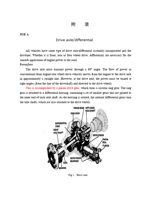
附录附录ADrive axle/differentialAll vehicles have some type of drive axle/differential assembly incorporated into the driveline. Whether it is front, rear or four wheel drive, differentials are necessary for the smooth application of engine power to the road.PowerflowThe drive axle must transmit power through a 90°angle. The flow of power in conventional front engine/rear wheel drive vehicles moves from the engine to the drive axle in approximately a straight line. However, at the drive axle, the power must be turned at right angles (from the line of the driveshaft) and directed to the drive wheels.This is accomplished by a pinion drive gear, which turns a circular ring gear. The ring gear is attached to a differential housing, containing a set of smaller gears that are splined to the inner end of each axle shaft. As the housing is rotated, the internal differential gears turn the axle shafts, which are also attached to the drive wheels.Fig 1 Drive axleRear-wheel driveRear-wheel-drive vehicles are mostly trucks, very large sedans and many sports car and coupe models. The typical rear wheel drive vehicle uses a front mounted engine and transmission assemblies with a driveshaft coupling the transmission to the rear drive axle. Drive in through the layout of the bridge, the bridge drive shaft arranged vertically in the same vertical plane, and not the drive axle shaft, respectively, in their own sub-actuator with a direct connection, but the actuator is located at the front or the back of the adjacent shaft of the two bridges is arranged in series. Vehicle before and after the two ends of the driving force of the drive axle, is the sub-actuator and the transmission through the middle of the bridge. The advantage is not only a reduction of the number of drive shaft, and raise the driving axle of the common parts of each other, and to simplify the structure, reduces the volume and quality.Fig 2 Rear-wheel-drive axleSome vehicles do not follow this typical example. Such as the older Porsche or Volkswagen vehicles which were rear engine, rear drive. These vehicles use a rear mounted transaxle with halfshafts connected to the drive wheels. Also, some vehicles were produced with a front engine, rear transaxle setup with a driveshaft connecting the engine to the transaxle, and halfshafts linking the transaxle to the drive wheels.Differential operationIn order to remove the wheel around in the kinematics due to the lack of co-ordination about the wheel diameter arising from a different or the same rolling radius of wheel travel required, inter-wheel motor vehicles are equipped with about differential, the latter to ensure that the car driver Bridge on both sides of the wheel when in range with a trip to the characteristics of rotating at different speeds to meet the requirements of the vehicle kinematics.Fig 3 Principle of differentialThe accompanying illustration has been provided to help understand how this occurs.1.The drive pinion, which is turned by the driveshaft, turns the ring gear.2.The ring gear, which is attached to the differential case, turns the case.3.The pinion shaft, located in a bore in the differential case, is at right angles to the axle shafts and turns with the case.4.The differential pinion (drive) gears are mounted on the pinion shaft and rotate with the shaft .5.Differential side gears (driven gears) are meshed with the pinion gears and turn with the differential housing and ring gear as a unit.6.The side gears are splined to the inner ends of the axle shafts and rotate the shafts as the housing turns.7.When both wheels have equal traction, the pinion gears do not rotate on the pinion shaft, since the input force of the pinion gears is divided equally between the two side gears.8.When it is necessary to turn a corner, the differential gearing becomes effective and allows the axle shafts to rotate at different speeds .Open-wheel differential on each general use the same amount of torque. To determine the size of the wheel torque to bear two factors: equipment and friction. In dry conditions, when a lot of friction, the wheel bearing torque by engine size and gear restrictions are hours in the friction (such as driving on ice), is restricted to a maximum torque, so that vehicles will not spin round. So even if the car can produce more torque, but also need to have sufficient traction to transfer torque to the ground. If you increase the throttle after the wheels slip, it will only make the wheels spin faster.Limited-slip and locking differential operationFig 5 Limited-slip differentialDifferential settlement of a car in the uneven road surface and steering wheel-driven speedat about the different requirements; but is followed by the existence of differential in theside car wheel skid can not be effective when the power transmission, that is, the wheel slipcan not produce the driving force, rather than spin the wheel and does not have enoughtorque. Good non-slip differential settlement of the car wheels skid on the side of the powertransmission when the issue, that is, locking differential, so that no longer serve a usefuldifferential right and left sides of the wheel can be the same torque.Limited-slip and locking differential operation can be divided into two major categories:(1) mandatory locking type in ordinary differential locking enforcement agencies toincrease, when the side of the wheel skid occurs, the driver can be electric, pneumatic ormechanical means to manipulate the locking body meshing sets of DIP Shell will be withthe axle differential lock into one, thus the temporary loss of differential role. Relatively simple structure in this way, but it must be operated by the driver, and good roads to stop locking and restore the role of differential.(2) self-locking differential installed in the oil viscosity or friction clutch coupling, when the side of the wheel skid occurs when both sides of the axle speed difference there, coupling or clutch friction resistance on the automatic, to make certain the other side of the wheel drive torque and the car continued to travel. When there is no speed difference on both sides of the wheel, the frictional resistance disappeared, the role of automatic restoration of differentials. More complicated structure in this way, but do not require drivers to operate. Has been increasingly applied in the car. About non-slip differential, not only used for the differential between the wheels, but also for all-wheel drive vehicle inter-axle differential/.Gear ratioThe drive axle of a vehicle is said to have a certain axle ratio. This number (usually a whole number and a decimal fraction) is actually a comparison of the number of gear teeth on the ring gear and the pinion gear. For example, a 4.11 rear means that theoretically, there are 4.11 teeth on the ring gear for each tooth on the pinion gear or, put another way, the driveshaft must turn 4.11 times to turn the wheels once. The role of the final drive is to reduce the speed from the drive shaft, thereby increasing the torque. Lord of the reduction ratio reducer, a driving force for car performance and fuel economy have a greater impact. In general, the more reduction ratio the greater the acceleration and climbing ability, and relatively poor fuel economy. However, if it is too large, it can not play the full power of the engine to achieve the proper speed. The main reduction ratio is more Smaller ,the speed is higher, fuel economy is better, but the acceleration and climbing ability will be poor.附录B驱动桥和差速器所有的汽车都装有不同类型的驱动桥和差速器来驱动汽车行驶。
汽车驱动桥外文文献翻译、中英文翻译、外文翻译
汽车驱动桥外文文献翻译、中英文翻译、外文翻译Drive AxleIn any vehicle。
there is always a drive ___ of whether it's a front。
rear。
or four-wheel drive。
differentials are crucial for the smooth n of engine power to the road.The drive axle must be able to transmit power through a 90-___ front-engine/rear-wheel drive vehicles。
the flow of power moves from the engine to the drive axle in a ___。
at the drive axle。
the power must be turned at a right angle (from the line of the driveshaft) and directed to the drive wheels.To do this。
a n drive gear is used to turn a ___ to the inner end of each axleshaft。
As the housing rotates。
the internal differential gears turn the axle shafts。
which are also attached to the drive wheels.二、中文翻译驱动桥所有车辆都有一种驱动桥/差速器组件集成到传动线中。
无论是前驱、后驱还是四驱,差动器都是平稳将发动机动力传递到路面上的必要条件。
驱动桥必须能够通过90度角传递动力。
在传统的前置发动机/后驱车辆中,动力流从发动机到驱动桥的方向是近似直线的。
中英文文献翻译—驱动桥相关介绍
附录附录ADriver introductions Bridge1. Features:Drive Bridge at the end of powertrain, and the basic function of which is to increase came from the drive shaft or transmission of torque, and a reasonable distribution of power to the left and right driving wheel, and also bear in the role of the frame or the road and Legislative body between the vertical, horizontal and vertical of power. Driven by the general bridge reducer, differential, wheels, transmission and drive axle housings and other components.2. The bridge design driver:(1) Drive bridge design should meet the following basic requirements:(1). Choice of the reduction ratio should be able to guarantee that vehicles have the power and the best fuel economy.(2). Dimensions small to ensure that the necessary ground clearance.(3). Transmission gears and other pieces of work stable and noise.(4). Under various load and speed with high transmission efficiency.(5). Guarantee sufficient strength, rigidity conditions, should strive for quality small, particularly unsprung mass should be as small as possible to improve vehicle ride comfort.(6). Oriented suspension and coordination of movement, to the drive axle, and the steering mechanism should be coordinated with campaigns.(7). Simple structure, and processing of, and easy to manufacture, enables easy adjustment.3. Drive Bridge Category3.1 non-driving axle-disconnectDisconnect-general non-driving axle, simple structure, low cost, reliable, widely used in a variety of truck, bus and the bus, in the majority of off-road vehicles and some cars also adopt this structure. Their specific structure, in particular the shell structure while the bridge is not the same, but there is one common characteristic is that Shell is a bridge support in the drive wheel about the rigid hollow beam, and the half-axle gear transmission components, such as installation of one of them. Then the whole drive axle, drive shaft driven wheel and some are in unsprung mass, larger vehicles unsprung mass, which is one of its shortcomings.Drive Axle size depends primarily on the outline of the main types reducer. In the tire size and drive underneath the minimum ground clearance has been determined by circumstances, it defines the diameter of the driven gear reducer size. Ratio of a given condition, if the single-stage reducer can not meet the requirements of ground clearance, with the dual-class structure. In the two-stage reducer, the two usually on a main gear reducer shell reducer, can also slow gear as a second-class round-reducer. The round-reducer: In order to improve cross-country motor vehicle ground clearance, can be a spur gear consisting of round-gear reducer initiatives under its follower of the vertical top gear; buses to reduce vehicle height and the center of mass of train floors height, so as to enhance stability and the convenience of the passengers get on and off, can be round-gear reducer initiatives under its vertical driven gear beneath some double-decker bus in order to further reduce the compartment floor height in a round-Gear reducer At the same time, the main reducer and differential assembly also moved to the driver's side wheel.In a few large-scale high-speed bus engine, multi-bridge drive vehicle and ultra-heavy laden car, and sometimes used for the worm reducer, it not only has the quality of small, compact size of circumstances can be large and transmission ratio Smoothing the merits of silent work, and the overall layout of the car is very convenient.3.2-drive axle disconnectDisconnect-drive axle different from the non-driving axle-disconnect the obvious characteristics of a connection is that the former does not drive the wheels about the rigidity of the overall casing or beam. Disconnect drive bridge is the bridge sub-shell, and can be done between the relative motion, such as off-the bridge. In addition, it always match with independent suspension, it is also known as the independent suspension bridge driver. The middle of this bridge, the main reducer and differential, are mounting in the frame beamsinside or on the floor, or backbone of the frame. Lord reducer, and the driveshaft and differential wheel drive part of the quality of transmission quality on all spring. As both sides of the drive wheel independent suspension can be used to the site relative to each other frame for the upper and lower compartments or swing, with a corresponding demand on the drive wheel and the gear casing or casing for the corresponding swing.The hoisting of the type of vehicle assembly and elastic damping device components and characteristics of the work is to determine vehicle ride comfort of the main factors, and the quality of auto parts spring the size of their ride also have a marked impact. Disconnect-drive axle unsprung mass smaller, independent suspension with the match, which drive the wheels of contact with the ground and on all-terrain better adaptability, which can greatly reduce car running on uneven road vibration and the tilt train, travelling to the vehicle's ride and the average driving speed, reducing the wheels and axles on the dynamic load and parts, increasing its reliability and service life. However, due to disconnect the drive Bridge and the independent suspension with the match of the complex structure, this structure is mainly seen on the ride comfort of the higher part of sedans and some off-road vehicle, and the latter more than a light following riders Bridge drive vehicles or heavy-duty off-road vehicle.3.3 Bridge over drive layoutIn order to improve loading and adoption of some medium - and heavy-duty vehicles and all over the use of off-road vehicles are driven more bridge, and often used 4,6 × 4 × 8 × such as 6,8-driven type. Multi-Bridge driver in the circumstances, the driving force at the drive actuator pass in the way the two bridges. The two corresponding power transmission, the Multi-Bridge drive vehicle driving axle layout patterns into non-hollow and hollow. The former in order to force the pass at the drive actuator bridge to the actuator from the drive axle by its own dedicated power transmission drive shaft, not only to increase the number of drive shaft, and the cause of the drive axle Bridge parts in particular Shell, and other major parts Semiaxle not universal. On the 8 × 8 vehicle, this non-drive-through bridge is even more inappropriate, but also a difficult layout.In order to solve the above problems, modern bridges are used in cars driven through the drive axle-type layout.In the drive-through layout of the bridge, the bridge driveshaft layout in the same vertical longitudinal plane, and were not the driving axle drive shaft and use their own sub-actuator directly connected, but in front of the actuator or the back of the two adjacent bridge driveshaft is the tandem arrangement. The two ends of the car after driving axle impetus by the actuator and transmission through the middle of the bridge. The advantage is not only reduce the number of drive shaft, but also increase the driving axle parts of the mutual general, and to simplify the structure, reducing the size and quality. This vehicle design (such as car variant), manufacturing and maintenance, convenient4. Drive axle componentsDriven mainly by the main bridge reducer, differential, half-axle and drive axle housings and other components.1. Lord reducerReducer to change the general direction of transmission, reduce speed and increase torque to ensure that there are sufficient vehicles and the driving force of the appropriate speed Paper. Reducer more main types, single-stage, two-stage, two-speed, such as round-reducer.(1) single-stage main reducerBy achieving a gear reducer deceleration devices, known as a single-stage reducer. Its structure is simple, light weight, Dongfeng BQl090 type light, widely used on medium-duty truck.( 2) Two-stage main reducerSome of the larger truck load for a slowdown than larger, single-level main reducer drive, moving from the diameter of gear must be increased, it will affect the drive axle ground clearance, a two-reducer . Often referred to as the two-stage reducer. There are two double-reducing gear reducer, to the two-twisting by deceleration.To enhance the meshing of gears cone smooth and strength, the first vice-gear reducer is spiral bevel gears. Two helical gear is the result of Vice gear.Active bevel gear rotation, led a round-driven rotary gear, thus completing a slowdown. Second-class deceleration initiative Gear Driven and bevel gear and a rotating coaxial, and driven gear driven rotary cylinder, a second-class deceleration. Driven by cylindrical gear installed in the differential case, therefore, when the follower cylinder gear rotates, and through the half axle differential rotation that drive the wheels. 2. DifferentialAbout half axle differential to connect, to enable both sides of the wheels at different angular velocity of rotation torque transmission. Guarantee the normal wheels rolling. Some bridges-driven cars, in the actuator or in the hollow shaft of the transmission are available differential, known as bridge between differential. Its role in the automotive turn or uneven traffic on the road, before and after the drive wheel differential between role.At present domestic cars and other types of vehicles in the basic use of the symmetrical cone ordinary differential gear. Symmetric bevel gear from the planetary gear differential, half axle gear, planetary gear shaft (axle or a direct cross-axis) and differential shell components.Most car-use planetary gear differential, ordinary differential bevel gear cone by two or four planetary gears, gear shaft, the two conical about half axle differential gear and shell components.3. SemiaxleSemi-axle differential is the torque came to pass wheels, rotating wheel drive, and promote car travelling solid shaft. Since the installation of wheels different structures, and the force Semiaxle also different. Therefore, Semiaxle divided into floating, semi-floating, 3 / 4 floating three types.(1) Full-floating SemiaxleGenerally large and medium-sized cars are used all floating structures. Semiaxle end of the spline and with the half-axle differential gear connected to the outer end Semiaxle forging a flange, with bolts and wheels connected. Wheel through two further away from the text of Tapered Roller Bearings for the half axle casing. Semiaxle bridge shell casing pressure and after one match, composition drive axle housings. Supporting the use of such forms, and the bridge shell Semiaxle not directly linked to Semiaxle driving torque not only bear to bear any moment, such Semiaxle called the "floating" half axle. The so-called "floating" that is not half axle bending load.Floating Semiaxle all, the end-to-flange and shaft into one. But there are also some truck into separate parts of the flange, and a set of keys to spend half axle, in the end. As a result, the two ends are Semiaxle spline can be used for the first.(2) semi-floating SemiaxleSemi-axle semi-floating with all of the floating-the same does not bear bending and torsion. Aloof-supported through a direct bearing on the inside half axle casing. Supportingthis approach will bear moment Semiaxle outer end. Therefore, in addition to this Banxiu torque transmission, but also to sustain local moment, the semi-called floating Semiaxle. This structure type mainly used for small buses.(3), 3 / 4 floating Semiaxle3 /4 floating Semiaxle is subject to the degree of bending short range semi-floating and the entire floating between. Application of this type currently Semiaxle little Xiaowoche only on the individual applications, such as Warsaw M20 car.附录B驱动桥相关介绍一.功能:驱动桥处于动力传动系的末端,其基本功能是增大由传动轴或变速器传来的转矩,并将动力合理的分配给左、右驱动轮,另外还承受作用于路面和车架或车身之间的垂直立、纵向力和横向力。
重型商用车驱动桥设计翻译

华南理工大学广州汽车学院本科生毕业设计(论文)翻译英文原文名DRIVE AXLE ASSEMBLIES中文译名驱动桥系别汽车工程系专业班级车辆工程学生姓名陈威指导教师上官文斌填表日期2011-5-19二〇一一年五月英文原文版出处:Dirk Spindler Georg von Petery INA-Schaeffler KG. Angular Contact Ball Bearings for a Rear Axle Differential.SAE ,2003译文成绩:指导教师(导师组)签名:译文:驱动桥在学习本章之后,你将了解不同类型驱动桥的组成,并能列举不同种类的驱动桥;比较后桥与前桥的不同之处;描述驱动桥的工作原理。
驱动桥有很多重要作用。
它可以使车轮回正,控制车轮滚动,可以使其中一个车轮的转速比另外一个车轮快,两个车轮均可获得转矩。
驱动桥可以获得来自于车轮的反作用力,通过弹簧,操纵杆等将作用力传到车架上。
驱动桥在车轮制动器被安装的基础上通过弹簧来固定,并获得簧上质量。
很显然,驱动桥需要使用高质量的材料来制作。
结构后桥的几个基本组成部分:桥壳,半轴,差速器。
桥壳桥壳通常是由钢板模压件焊接在一起而制成的。
桥壳的中心部分是由铸钢制成的。
有两种类型的桥壳常被使用:整体式桥壳(应用广泛)和分段式桥壳(应用较少)是由两个或者更多的部分组成。
车桥两个车桥在桥壳的内部,它们在内部相接触,在某些位置它们是不接触的。
外部的凸出端附在车轮和轮毂上。
内部端被花键固定在差速器上,外端被滚子轴承所固定。
连接轮两种方法被应用于驱动桥的轮毂上。
一种方法是在驱动桥一端用拔销来固定,另一端通过凸缘固定。
半轴的类型半轴有三种基本的类型,全浮式, 3/4浮式和半浮式。
大多是汽车采用半浮式,大部分货车采用全浮式半轴支承。
如果半轴折断,车轮将停止转动。
驱动桥汽车转弯时的工况与普通行驶时的不同,必须使用一个叫做差速器的单元使两个半轴都获得动力,让左右驱动车轮的行驶速度不同。
中英文文献翻译—驱动桥的构造
中英文文献翻译—驱动桥的构造附录AThe structure of driving axleThe driving axle is in the power power transmission the terminal, its basic function increases the torque which transmits by the drive shaft or the transmission gearbox, and power reasonable assignment for left and right driving gear, moreover also withstands the function vertical sets up, the longitudinal force and the transverse force between the road surface and the frame or the automobile body.The driving axle generally by the main gear box, the differential device, the wheel transmission device and the driving axle shell and so on is composed.1.Driving axle design:The driving axle design must satisfy following basic request:1). Choice main reduction gear ratios ought to be able to guarantee the automobile has the best power and the fuel economy.2). External dimensions must be small, guaranteed has the necessity ground clearance.3). Gears and other transmission piece works do steadily, the noise is small.4). Has the high transmission efficiency under each kind of rotational speed and the load.5). Under the guarantee enough intensity, the rigidity condition, should make every effort the quality to be small, under the reed the quality should be as far as possible small in particular, improves the automobile smoothness.6). Coordinated with the suspension fork guidance organization movement, regarding changes the driving axle, butalso should coordinate with the rotation gear movement.7). Structures are simple, the processing technology capability is good, the manufacture is easy, disassembling, the adjustment is convenient.2.Driving axle classificationThe driving axle minute non-separation type with separates the type two big kinds.1).Non-separation type driving axleThe non-separation type driving axle also is called the integral-type driving axle, its rear axle drive pipe and main gear box shell with shaft casing rigidly connected whole Liang, thus the both sides rear axle and the driving gear swing related, passes the elastic part andthe frame is connected.It by the driving axle shell 1, the main gear box, the differential device and the rear axle is composed.2). Separation type driving axleThe driving axle uses the independent suspension fork, namely the main gear box shell fixes on the frame, the both sides rear axle and the driving gear can be opposite in the rolling plane in the chassis have the relative motion to be called the separation type driving axle.In order to coordinates with the independent suspension fork, fixes the main gear box shell in the frame (or automobile body) on, the driving axle shell partition and through the hinge joint, or no longer has the driving axle shell other parts besides the main gear box shell.In order to meet the need which about the driving gear independence beats, between the differential device and between wheel rear axle each section connects with the universal joint.3.Drive axle of compositionMainly by the reducer drive, and half axle and drive axle shell, etc.1) .Main reducerThe speed reducer is usually used to change the direction of transmission, reduce speed and increase torque, guarantee cars have enough force and appropriate speed. Main reducer, have more single type, double, double speed reducer, wheel edges.a). Single main reducerBy a reduction gear reducer realization of single reducer, called. Its simple structure, light weight, dongfeng BQl090, light, medium sized truck was widely used in automobile.b). Double main reducerIn some large trucks, load demand is bigger than the slow, with single main reducer drive, driven gear diameter increases, affect to the ground clearance drive, so using twice. Usually called doublestage reducer. Two groups of double reduction gear reducer, increasing torsional twice slowdown.To improve the tapered gear pair of meshing smoothness and strength, the level of spiral bevel gears reduction gear pair is. Second gear pair is helical gears for support.Active tapered gear rotating, drive driven circular gear rotating, thus completing silver. Level Article 2 the initiative of cylindrical gears and driven tapered gear coaxial and rotate together, and bring about a follower of cylindrical gears rotate, 2. Because a follower of cylindrical gears installed in differential shell, so, when a follower of cylindrical gearsturning, through the differential and half shaft is driven wheel rotation.2).DifferentialAround half shaft are used to connect differential wheel, canmake the sides with different velocity rotating torque simultaneously. Ensure the normal scroll wheel. Some more, in the car driver bridge or in the breakthrough of thansfer transmission shaft with differential between, also called the bridge between differential. Its role in the car is in turn or flat road to drive wheels, and generate differential between the role.Current domestic cars and other cars are adopted symmetric bevel gear ordinary differential. Symmetrical type gear differential planetary gear, half of planetary gear axle shaft gear, or a cross (direct axis) and differential shell, etc.Most current car using differential planetary gear, ordinary bevel gear differential by two or four conical planetary gear and planetary gear axle, two cone half shaft gear and differential shell, etc.3). Half axleHalf shaft are coming to the differential wheel, drive torque to move the car wheel rotation, the solid shaft. Due to the different structure, installation of hub axial force and the different also. Therefore, half shaft are divided into the floating, use, three/four floating three types.a). Howo fou-point suspending half axleGeneral big, medium-sized cars are adopted the floating structure. Half of the spline shaft inside with the half shaft with differential gears connected to the end of the half shaft are forging flanges, bolts and wheel connection. Hub through two far apart WenCheng tapered roller bearings in half a collar. Half a collar and driving axle shell pressure to drive, composition. Use this form, half shaft bearing no direct link with the bridge housing, half shaft driving torque and not only bear any moment under this half shaft are called "the floating" half axle. The so-called"float" means half shaft are not bending load.The float, the half axle shaft for lugs and made one. But there are some heavy trucks to lugs, and made the individual parts of the spline shaft in the half. Therefore, both ends of the spline shaft is used, can HuanT ou.b). Use half axleUse of half axle within the same with the client, not withstand float bending-torsional. The client through a direct bearing on the inside of half axle shell. This means that will support the half axle under bending moment. Therefore, the half sleeve torque, except underbending moment, local use half shaft is called. This structure is mainly used for certain.The red flag brand limousines CA7560 type of thing. The half shaft are not bending moment, the client will inherit all external use, so called bending support.c). 3/4 floating half axleThree-quarters of floating half shaft are short of bending degree between use and the floating. This type of half axle currently used in XiaoWoChe, only on individual applications, such as M20 type car. Warsaw,4). The bridge housinga). Integral bridge housingIntegral bridge housing for the intensity and rigidity, and facilitate the good performance of the installation, adjustment and maintenance, and widely used. Integral bridge housing for manufacturing methods, which can be divided into different midway through the whole cast type, the steel casting and stamping steel welding etc.b). Drive axle shell segmentedSection type bridge housing generally fall into two, one will DuanLianCheng two by bolts. Bridge housing is segmented to casting and machining.附录B驱动桥的构造驱动桥处于动力传动系的末端,其基本功能是增大由传动轴或变速器传来的转矩,并将动力合理的分配给左、右驱动轮,另外还承受作用于路面和车架或车身之间的垂直立、纵向力和横向力。
- 1、下载文档前请自行甄别文档内容的完整性,平台不提供额外的编辑、内容补充、找答案等附加服务。
- 2、"仅部分预览"的文档,不可在线预览部分如存在完整性等问题,可反馈申请退款(可完整预览的文档不适用该条件!)。
- 3、如文档侵犯您的权益,请联系客服反馈,我们会尽快为您处理(人工客服工作时间:9:00-18:30)。
Appendix
China in the first half of 2008 about 93 million trucks accumulative total sales of cars, vans 61 million vehicles, year-on-year growth of 20.2%, visible light car in commercial car production has a large proportion. And driving axle is very important in the vehicle driving axle is the important car auto bearing assembly, auto frame and integral by suspension of body vertical force, to lead the longitudinal forces, transverse force and torque, and impact load; Driving axle also delivers the transmission, the maximum torque reaction is under.
Automobile driving axle structure and design parameters in addition to the reliability of the automobile and durability have important influence on the outside, also for the automobile driving performance such as power, economy, smooth, through sex, mobility Automobile driving axle design involves the mechanical parts and components is widely to these varieties, spare parts, components and assemblies manufacturing also almost want to design to all modern machinery manufacturing process, design a simple structure, reliable operation and low cost, can greatly reduce the drive axle of the total cost of the vehicle production, promote economic development, and car to drive through the car studying and designing practice, can better learning and mastery of the modern car design and mechanical design of the comprehensive knowledge and skills, and the overall thinking and operation skill check, drawing, is the very important link, so ontology of a structure design of fine vans axles has certain Automobile driving axle is one of the main parts car, its basic function is to enlarge the shaft or by the torque transmission spread, then torque distribution to drive wheels, and make about driving wheel has about vehicle movement required differential function; Axles in the end of powertrain system, choose proper Lord slowdown, ensure cars than with sufficient ground clearance is achieved, gear and other transmission job need to ensure smooth are the parameters, and even bear effect on the pavement drive axle and frame or carrying body vertical force, the lead between transverse and longitudinal force and torque force. Driving axle quality, performance will have a direct impact on the vehicle's safety, economy, comfort and reliability. After the car driving axle design can make the students' comprehensive by using their This thesis research aims to overall matching car by driving axle Lord finish design of gear reducer, differential component such as type of design and calculation, and complete checking and comprehensive design single main reducer, then the batch Through the design of the vehicle driving axle should also master the understanding, including each component interaction between the body and the electrical
system, the influence and cooperate to drive axle of the process and therefore more familiar with vehicle mastery. That in the future the production and living effectly use.
附录
我国2008年上半年货车累计销售约93万辆,其中轻型货车61万辆,同比增长20.2%,可见轻型汽车在商用汽车生产中占有很大的比重。
而且驱动桥在整车中十分重要,汽车驱动桥是汽车的重要总成,承载着汽车车架及承载式车身经悬架给予的铅垂力、纵向力、横向力及其力矩,以及冲击载荷;驱动桥还传递着传动系中的最大转矩,桥壳还承受着反作用力矩。
汽车驱动桥结构型式和设计参数除对汽车的可靠性与耐久性有重要影响外,也对汽车的行驶性能如动力性、经济性、平顺性、通过性、机动性和操动稳定性等有直接影响。
汽车驱动桥设计涉及的机械零部件及元件的品种极为广泛,对这些零部件、元件及总成的制造也几乎要设计到所有的现代机械制造工艺,设计出结构简单、工作可靠、造价低廉的驱动桥,能大大降低整车生产的总成本,推动汽车经济的发展,并且通过对汽车驱动桥的学习和设计实践,可以更好的学习并掌握现代汽车设计与机械设计的全面知识和技能,以及整体的思维和运算校核等本领,绘图也是其中非常重要的环节,所以本题设计一款结构优良的轻型货车驱动桥具有一定的实际意义
汽车驱动桥是汽车的主要部件之一,其基本功用是增大由传动轴或变速器传来的转矩,再将转矩分配给左右驱动车轮,并使左右驱动车轮具有汽车行驶运动所要求的差速功能;驱动桥处于动力传动系的末端,选择适当的主减速比,保证汽车具有足够的离地间隙,齿轮及其他传动件工作平稳都是需要保证的参量,同时驱动桥还要承受作用于路面和车架或承载车身之间的铅垂力、纵向力、横向力及其力矩。
驱动桥质量、性能的好坏直接影响整车的安全性、经济性、舒适性、可靠性。
设计汽车后驱动桥能使学生综合运用所学专业知识,熟练CAD绘图技能。
本设计的研究目的在于通过对汽车整体的匹配性设计完成驱动桥的主减速器,差速器等零部件型号的设计与计算,并完成校核和对单机主减速器的全面设计,然后进行批量生产。
完成所要求的课题设计的任务。
通过设计驱动桥还应掌握对整车的了解,其中包括各个部件的相互作用关系,车身和电器系统对驱动桥的影响和配合的过程,因此对整车有更熟悉更全面的掌握。
以至在今后的生产生活中得到更有效的运用。