仪表板外文文献翻译、中英文翻译、外文翻译
汽车导航外文翻译中英
Automotive navigation systemAn automotive avigation system is a satellite navigation system designed for use in automobiles. It typically uses a GPS navigation device to acquire position data to locate the user on a road in the unit's map database. Using the road database, the unit can give directions to other locations along roads also in its database. Dead reckoning using distance data from sensors attached to the drivetrain, a gyroscope and an accelerometer can be used for greater reliability, as GPS signal loss and/or multipath can occur due to urban canyons or tunnels.Some sorts can be taken out of the car and used hand-held while walking. HistoryAutomotive navigation systems were the subject of extensive experimentation, including some efforts to reach mass markets, prior to the availability of commercialGPS.Most major technologies required for modern automobile navigation were already established when the microprocessor emerged in the 1970s to support their integration and enhancement by computer software. These technologies subsequently underwent extensive refinement, and a variety of system architectures had been explored by the time practical systems reached the market in the late 1980s. Among the other enhancements of the 1980s was the development of color displays for digital maps and of CD-ROMs for digital map storage.However, there is some question about who made the first commercially available automotive navigation system. There seems to be little room for doubt that Etak was first to make available a digital system that usedmap-matching to improve on dead reckoning instrumentation. Etak's systems, which accessed digital map information stored on standard cassette tapes, arguably made car navigation systems practical for the first time.[2] However, Japanese efforts on both digital and analog systems predate Etak's founding.Steven Lobbezoo developed the first commercially available satellite navigation system for cars. It was produced in Berlin from start 1984 to January 1986. Publicly presented first at the Hannover fair in 1985 in Germany, the system was shown in operation on the evening news from the first German television channel in that year. It used a modified IBM PC, a large disc for map data and a flat screen, built into the glove compartment. It was called Homer Alpine claims to have created the first automotive navigation system in 1981.However, according to the company's own historical timeline,[3] the company claims to have co-developed an analog automotive navigation product called the Electro Gyrocator, working with Honda. This engineering effort was abandoned in 1985. Although there are reports of the Electro Gyrocator being offered as a dealer option on the Honda Accord in 1981, it's not clear whether an actual product was released, whether any customers took delivery of an Electro Gyrocator-equipped Accord, or even whether the unit appeared in any dealer showrooms; Honda's own official history appears to pronounce the Electro Gyrocator as not practical.Honda claims[4] to have created the first navigation system starting in 1983, and culminating with general availability in the 1990 Acura Legend. The original analogElectro Gyrocator system used an accelerometer to navigate using inertial navigation, as the GPS system was not yet generally available. However, it appears from Honda's concessions in their own account of the Electro Gyrocator project that Etak actually trumped Honda's analog effort with a truly practical digital system, albeit one whose effective range of operation was limited by the availability of appropriately digitized street map data.TechnologyVisualizationNavigation systems may (or may not) use a combination of any of the following:▪top view for the map▪top view for the map with the map rotating with the automobile (so that "up" on the map always corresponds to "forward" in the vehicle)▪bird's-eye view for the map or the next curve▪linear gauge for distance, which is redundant if a rotating map is used ▪numbers for distance▪schematic pictograms▪voice promptsRoad databaseContentsThe road database is a vector map of some area of interest. Street names or numbers and house numbers are encoded as geographic coordinates so that the user can find some desired destination by street address .Points of interest will also be stored with their geographic coordinates. Point of interest specialties include speed cameras, fuel stations, publicparking, and "parked here".Contents can be produced by the user base as their cars drive along existing streets and communicating via the internet, yielding a free and up-to-date map.Physical Storage FormatThe Physical Storage Format (PSF) initiative is an industry grouping of car manufacturers, navigation system suppliers and map data suppliers whose objective is the standardization of the data format used in car navigation systems, as well as allow a map update capability. Standardization would improve interoperability, specifically by allowing the same navigation maps to be used in navigation systems from 19 manufacturers. Companies involved include BMW, Volkswagen, Daimler,Renault, ADIT, Aisin AW, Alpine Electronics, Navigon, Bosch, DENSO, Mitsubishi, Harman Becker, Panasonic, PTV, Continental AG, Clarion, Navteq, Tele Atlas and Zenrin.MediaThe road database may be stored in solid state read-only memory (ROM), optical media (CD or DVD), solid state flash memory, magnetic media (hard disk), or a combination. A common scheme is to have a basemap permanently stored in ROM that can be augmented with detailed information for a region the user is interested in. A ROM is always programmed at the factory; the other media may bepreprogrammed, downloaded from a CD or DVD viaa computer or wireless connection (bluetooth, Wi-Fi), or directly used utilizing a card reader.Some navigation device makers provide free map updates for their customers. These updates are often obtained from the vendor's website, which is accessed by connecting the navigation device to a PC.汽车导航系统汽车导航系统是一个设计供汽车使用的卫星导航系统。
汽车车辆专业悬架外文文献翻译、中英文翻译、外文翻译
外文文献(二)外文原文Abstract:To improve the suspension performance and steering stability of light vehicles, we built a kinematic simulation model of a whole independent double-wishbone suspension system by using ADAMS software, created random excitations of the test platforms of respectively the left and the right wheels according to actual running conditions of a vehicle, and explored the changing patterns of the kinematic characteristic parameters in the process of suspension motion. The irrationality of the suspension guiding mechanism design was pointed out through simulation and analysis, and the existent problems of the guiding mechanism were optimized and calculated. The results show that all the front-wheel alignment parameters, including the camber, the toe, the caster and the inclination, only slightly change within corresponding allowable ranges in design before and after optimization. The optimization reduces the variation of the wheel-center distance from 47.01 mm to a change of 8.28 mm within the allowable range of -10 mm to 10 mm, promising an improvement of the vehicle steering stability. The optimization also confines the front-wheel sideways slippage to a much smaller change of 2.23 mm; this helps to greatly reduce the wear of tires and assure the straight running stability of the vehicle. Keywords:vehicle suspension; vehicle steering; riding qualities; independent double-wishbone suspension; kinematic characteristic parameter; wheel-center distance; front-wheel sideways slippage1 IntroductionThe function of a suspension system in a vehicle is to transmit all forces and moments exerted on the wheels to the girder frame of the vehicle, smooth the impact passing from the road surface to the vehicle body and damp the impact-caused vibration of the load carrying system. There are many different structures of vehicle suspension, of which the independent double-wishbone suspension is most extensively used. An independent double-wishbone suspension system is usually a group of space RSSR (revolute joint - spherical joint -spherical joint - revolute joint) four-bar linkage mechanisms. Its kinematic relations are complicated, its kinematic visualization is poor, and performance analysis is very difficult. Thus, rational settings of the position parameters of the guiding mechanism are crucial to assuring good performance of the independent double-wishbone suspension. The kinematic characteristics of suspension directly influence the service performance of the vehicle, especially steering stability, ride comfort, turning ease, and tire life.In this paper, we used ADAMS software to build a kinematic analysis model of an independent double-wishbone suspension, and used the model to calculate and optimize the kinematic characteristic parameters of the suspension mechanism. The optimization results are helpful for improving the kinematic performance of suspension.2 Modeling independent double-wishbone suspensionThe performance of a suspension system is reflected by the changes of wheel alignment parameters when the wheels jump. Those changes should be kept within rational ranges to assure the designed vehicle running performance. Considering the symmetry of the left and right wheels of a vehicle, it is appropriate to study only the left or the right half of the suspension system to understand the entire mechanism, excluding the variation of WCD (wheel center distance). We established a model of the left half of an independent double-wishbone suspension system as shown in Figure 1.3 Kinematic simulation analysis of suspension modelConsidering the maximum jump height of the front wheel, we positioned the drives on the translational joints between the ground and the test platform, and imposed random displacement excitations on the wheels to simulate the operating conditions of a vehicle running on an uneven road surface.The measured road-roughness data of the left and right wheels were converted into the relationship between time and road roughness at a certain vehicle speed. The spline function CUBSPL in ADAMS was used to fit and generate displacement-time history curves of excitation. The simulation results of the suspension system before optimization are illustrated in Figure 2.The camber angle, the toe angle, the caster angle and the inclination angle change only slightly within the corresponding designed ranges with the wheel jumping distance. This indicates an under-steering behavior together with an automatic returnability, good steering stability and safety in a running process. However, WCD decreases from 1 849.97 mm to 1 896.98 mm and FWSS from 16.48 mm to -6.99 mm, showing remarkable variations of 47.01 mm and 23.47 mm, respectively. Changes so large in WCD and FWSS are adverse to the steering ease and straight-running stability, and cause quick wear, thus reducing tire life.For independent suspensions, the variation of WCD causes side deflection of tires and then impairs steering stability through the lateral force input. Especially when the right and the left rolling wheels deviate in the same direction, the WCD-caused lateral forces on the right and the left sides cannot be offset and thus make steering unstable. Therefore, WCD variation should be kept minimum, and is required in suspension design to be within the range from -10 mm to 10 mm when wheels jump. It is obvious that the WCD of non-optimized structure of the suspension system goes beyond this range. The structure needs modifying to suppress FWSS and the change of WCD with the wheel jumping distance.ADMAS software is a strong tool for parameter optimization and analysis. It creates a parameterization model by simulating with different values of model design variables, and then analyzes the parameterization based on the returned simulation results and the final optimization calculation of all parameters. During optimization, the program automatically adjusts design variables to obtain a minimum objective function [8-10]. To reduce tire wear and improve steering stability, the T able 1 V alues of camber angle α , toe angle θ , caster angle γ and inclination angle β before and after optimizationTable 1 The data tables of optimize the results4 ConclusionsThe whole kinematic simulation model of an independent double-wishbone suspension system built by using ADAMS software with the left and the right suspension parts under random excitations can improve the calculation precision by addressing the mutual impacts of kinematic characteristic parameters of the left and the right suspension parts under random excitations. The optimization can overcome the problem of the too large variation of WCD and overly large FWSS with the wheel jumping distance. The kinematic characteristic parameters of the suspension system reach an ideal range, demonstrating that the optimization protocol is feasible. From a practical perspective, the optimization is expected to reduce tire wear, and remarkably improve suspension performance and vehicle steering stability.Figure 1 simple picture of suspensionFigure 2 Curve with the parameters of the suspension译文摘要:为了提高轻型车辆性能和行驶稳定,我们使用ADAMS 软件建立一个独立双横臂悬架系统运动仿真模型,并建立随机激励的测试平台,根据车辆实际运行条件,探讨悬架的运动学特征参数的变化。
电气工程及其自动化专业_外文文献_英文文献_外文翻译_plc方面.
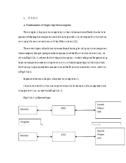
1、外文原文A: Fundamentals of Single-chip MicrocomputerTh e si ng le -c hi p m ic ro co mp ut er i s t he c ul mi na ti on of both t h e de ve lo pm en t of the dig it al com pu te r an d th e in te gr at ed c i rc ui t arg ua bl y t h e tow m os t s ig ni f ic an t i nv en ti on s o f t he 20th c e nt ur y [1].Th es e tow type s of arch it ec tu re are foun d in sin g le -ch i p m i cr oc om pu te r. Som e empl oy the spli t prog ra m/da ta me mo ry of the H a rv ar d ar ch it ect u re , sh ow n in Fig.3-5A -1, oth ers fo ll ow the p h il os op hy , wi del y ada pt ed for gen er al -p ur po se com pu te rs and m i cr op ro ce ss o r s, o f ma ki ng no log i ca l di st in ct ion be tw ee n p r og ra m and dat a me mo ry as in the Pr in ce to n arch ite c tu re , show n i n Fig.3-5A-2.In gen er al ter ms a sin gl e -chi p mic ro co mp ut er i sc h ar ac te ri zed b y t he i nc or po ra ti on of a ll t he un it s of a co mp uter i n to a sin gl e d ev i ce , as sho wn inFi g3-5A -3.Fig.3-5A-1 A Harvard typeFig.3-5A-2. A conventional Princeton computerFig3-5A-3. Principal features of a microcomputerRead only memory (ROM.R OM is usua ll y for the pe rm an ent,n o n-vo la ti le stor a ge of an app lic a ti on s pr og ra m .M an ym i cr oc om pu te rs and m are inte nd e d for high -v ol um e ap pl ic at ions a n d he nc e t h e eco n om ic al man uf act u re of th e de vic e s re qu ir es t h at t he cont en t s o f t he prog ra m me m or y be co mm it t ed perm a ne ntly d u ri ng the man ufa c tu re of ch ip s .Cl ea rl y, thi s im pl ie s a r i go ro us app ro ach to ROM cod e deve l op me nt sin ce cha ng es can not b e mad e afte r manu f a c tu re .Th is dev e lo pm en t proc ess may invo lv e e m ul at io n us in g aso ph is ti ca te d de ve lo pm en t sy ste m wit h a h a rd wa re emu la tio n cap ab il it y as w el l as the use o f po we rf ul s o ft wa re too ls.So me man uf act u re rs pro vi de add it io na l RO M opt i on s by i n cl ud in g in their ra n ge dev ic es wit h (or int en de d fo r use wit h u s er pro gr am ma ble me mo ry. Th e sim p le st of th es e is usu al ly d e vi ce whi ch can op er at e in a micro p ro ce ssor mod e by usi ng som e o f the inp ut /outp u t li ne s as an ad dr es s an d da ta b us fora c ce ss in g ex te rna l mem or y. Thi s t y pe of de vi ce can beh av ef u nc ti on al ly as th e sing le chip mi cr oc om pu te r from whi ch it is d e ri ve d al be it wit h re st ri ct ed I/O and a mod if ied ex te rn al c i rc ui t. The use of thes e d ev ic es is com mo n eve n in prod uc ti on c i rc ui ts wher e t he vo lu me does no tj us ti f y t h e d ev el o pm en t c osts o f c us to m o n -ch i p R OM [2];t he re c a n s ti ll bea s ignif i ca nt saving i n I /O and o th er c h ip s com pa re d to a conv en ti on al mi c ro pr oc es sor b a se d ci rc ui t. Mor e ex ac t re pl ace m en t fo r RO M dev i ce s ca n be o b ta in ed in th e fo rm of va ri an ts w it h 'p ig gy -b ack 'E P RO M(Er as ab le pro gr am ma bl e ROM s oc ke ts or dev ic e s with EPROM i n st ea d o f RO M 。
电气工程及其自动化专业 外文文献 英文文献 外文翻译 plc方面

1、外文原文(复印件)A: Fundamentals of Single-chip MicrocomputerTh e si ng le-ch i p mi cr oc om pu ter is t he c ul mi nat i on o f bo th t h e d ev el op me nt o f th e d ig it al com p ut er an d t he int e gr at ed ci rc ui ta r gu ab ly th e t ow m os t s i gn if ic ant i nv en ti on s o f t h e 20t h c en tu ry[1].Th es e to w typ e s of a rc hi te ctu r e ar e fo un d i n s in gl e-ch ip m i cr oc om pu te r. So m e em pl oy t he sp l it p ro gr am/d ata me mo ry o f th e H a rv ar d ar ch it ect u re, sh ow n i n -5A, ot he rs fo ll ow th e ph i lo so ph y, w i de ly a da pt ed fo r g en er al-p ur pos e c om pu te rs an d m i cr op ro ce ss or s, o f m a ki ng no lo gi c al di st in ct io n b e tw ee n p ro gr am a n d da t a m em ory a s i n th e Pr in cet o n ar ch it ec tu re,sh ow n in-5A.In g en er al te r ms a s in gl e-chi p m ic ro co mp ut er i sc h ar ac te ri zed b y the i nc or po ra tio n of al l t he uni t s o f a co mp ut er i n to a s in gl e dev i ce, as s ho wn in Fi g3-5A-3.-5A-1 A Harvard type-5A. A conventional Princeton computerFig3-5A-3. Principal features of a microcomputerRead only memory (ROM).R OM i s u su al ly f or th e p er ma ne nt, n o n-vo la ti le s tor a ge o f an a pp lic a ti on s pr og ra m .M an ym i cr oc om pu te rs an d mi cr oc on tr ol le r s a re in t en de d fo r h ig h-v ol ume a p pl ic at io ns a nd h en ce t he e co nom i ca l ma nu fa ct ure of t he d ev ic es r e qu ir es t ha t the co nt en ts o f the pr og ra m me mo ry b e co mm it te dp e rm an en tl y d ur in g th e m an uf ac tu re o f c hi ps . Cl ear l y, th is im pl ie sa ri g or ou s a pp roa c h t o R OM co de d e ve lo pm en t s in ce c ha ng es ca nn otb e m ad e af te r man u fa ct ur e .T hi s d e ve lo pm en t pr oce s s ma y in vo lv e e m ul at io n us in g a s op hi st ic at ed deve lo pm en t sy st em w i th a ha rd wa re e m ul at io n ca pa bil i ty a s we ll a s th e u se of po we rf ul so ft wa re t oo ls.So me m an uf act u re rs p ro vi de ad d it io na l RO M opt i on s byi n cl ud in g i n th ei r ra ng e de vi ce s wi th (or i nt en de d fo r us e wi th) u s er pr og ra mm ab le m em or y. Th e s im p le st of th es e i s us ua ll y d ev ice w h ic h ca n op er ate in a m ic ro pr oce s so r mo de b y usi n g so me o f th e i n pu t/ou tp ut li ne s as a n ad dr es s an d da ta b us f or acc e ss in g e xt er na l m e mo ry. T hi s t ype o f d ev ic e c an b e ha ve fu nc ti on al l y a s t he si ng le c h ip mi cr oc om pu te r fr om wh ic h i t i s de ri ve d a lb eit w it h r es tr ic ted I/O an d a mo di fie d e xt er na l ci rcu i t. T he u se o f t h es e RO Ml es sd e vi ce s is c om mo n e ve n in p ro du ct io n c ir cu it s wh er e t he v ol um e do es n o t ju st if y th e d e ve lo pm en t co sts of c us to m on-ch i p RO M[2];t he re c a n st il l b e a si g ni fi ca nt s a vi ng in I/O a nd ot he r c hi ps co mp ar ed t o a c on ve nt io nal mi cr op ro ce ss or b as ed c ir cu it. M o re e xa ctr e pl ac em en t fo r RO M d ev ic es c an b e o bt ai ne d in t he f o rm o f va ri an ts w i th 'pi gg y-ba ck'EP RO M(Er as ab le p ro gr am ma bl e ROM)s oc ke ts o rd e vi ce s w it h EP ROM i ns te ad o f R OM 。
电气 自动化 外文文献 外文翻译 英文文献

外文出处:Farhadi, A. (2008). Modeling, simulation, and reduction of conducted electromagnetic interference due to a pwm buck type switching power supply. Harmonics and Quality of Power, 2008. ICHQP 2008. 13th International Conference on, 1 - 6.Modeling, Simulation, and Reduction of Conducted Electromagnetic Interference Due to a PWM Buck Type Switching Power Supply IA. FarhadiAbstract:Undesired generation of radiated or conducted energy in electrical systems is called Electromagnetic Interference (EMI). High speed switching frequency in power electronics converters especially in switching power supplies improves efficiency but leads to EMI. Different kind of conducted interference, EMI regulations and conducted EMI measurement are introduced in this paper. Compliancy with national or international regulation is called Electromagnetic Compatibility (EMC). Power electronic systems producers must regard EMC. Modeling and simulation is the first step of EMC evaluation. EMI simulation results due to a PWM Buck type switching power supply are presented in this paper. To improve EMC, some techniques are introduced and their effectiveness proved by simulation.Index Terms:Conducted, EMC, EMI, LISN, Switching SupplyI. INTRODUCTIONFAST semiconductors make it possible to have high speed and high frequency switching in power electronics []1. High speed switching causes weight and volume reduction of equipment, but some unwanted effects such as radio frequency interference appeared []2. Compliance with electromagnetic compatibility (EMC) regulations is necessary for producers to present their products to the markets. It is important to take EMC aspects already in design phase []3. Modeling and simulation is the most effective tool to analyze EMC consideration before developing the products. A lot of the previous studies concerned the low frequency analysis of power electronics components []4[]5. Different types of power electronics converters are capable to be considered as source of EMI. They could propagate the EMI in both radiated and conducted forms. Line Impedance Stabilization Network (LISN) is required for measurement and calculation of conducted interference level []6. Interference spectrum at the output of LISN is introduced as the EMC evaluation criterion []7[]8. National or international regulations are the references forthe evaluation of equipment in point of view of EMC []7[]8.II. SOURCE, PATH AND VICTIM OF EMIUndesired voltage or current is called interference and their cause is called interference source. In this paper a high-speed switching power supply is the source of interference.Interference propagated by radiation in area around of an interference source or by conduction through common cabling or wiring connections. In this study conducted emission is considered only. Equipment such as computers, receivers, amplifiers, industrial controllers, etc that are exposed to interference corruption are called victims. The common connections of elements, source lines and cabling provide paths for conducted noise or interference. Electromagnetic conducted interference has two components as differential mode and common mode []9.A. Differential mode conducted interferenceThis mode is related to the noise that is imposed between different lines of a test circuit by a noise source. Related current path is shown in Fig. 1 []9. The interference source, path impedances, differential mode current and load impedance are also shown in Fig. 1.B. Common mode conducted interferenceCommon mode noise or interference could appear and impose between the lines, cables or connections and common ground. Any leakage current between load and common ground couldbe modeled by interference voltage source.Fig. 2 demonstrates the common mode interference source, common mode currents Iandcm1 and the related current paths[]9.The power electronics converters perform as noise source Icm2between lines of the supply network. In this study differential mode of conducted interference is particularly important and discussion will be continued considering this mode only.III. ELECTROMAGNETIC COMPATIBILITY REGULATIONS Application of electrical equipment especially static power electronic converters in different equipment is increasing more and more. As mentioned before, power electronics converters are considered as an important source of electromagnetic interference and have corrupting effects on the electric networks []2. High level of pollution resulting from various disturbances reduces the quality of power in electric networks. On the other side some residential, commercial and especially medical consumers are so sensitive to power system disturbances including voltage and frequency variations. The best solution to reduce corruption and improve power quality is complying national or international EMC regulations. CISPR, IEC, FCC and VDE are among the most famous organizations from Europe, USA and Germany who are responsible for determining and publishing the most important EMC regulations. IEC and VDE requirement and limitations on conducted emission are shown in Fig. 3 and Fig. 4 []7[]9.For different groups of consumers different classes of regulations could be complied. Class Afor common consumers and class B with more hard limitations for special consumers are separated in Fig. 3 and Fig. 4. Frequency range of limitation is different for IEC and VDE that are 150 kHz up to 30 MHz and 10 kHz up to 30 MHz respectively. Compliance of regulations is evaluated by comparison of measured or calculated conducted interference level in the mentioned frequency range with the stated requirements in regulations. In united European community compliance of regulation is mandatory and products must have certified label to show covering of requirements []8.IV. ELECTROMAGNETIC CONDUCTED INTERFERENCE MEASUREMENTA. Line Impedance Stabilization Network (LISN)1-Providing a low impedance path to transfer power from source to power electronics converter and load.2-Providing a low impedance path from interference source, here power electronics converter, to measurement port.Variation of LISN impedance versus frequency with the mentioned topology is presented inFig. 7. LISN has stabilized impedance in the range of conducted EMI measurement []7.Variation of level of signal at the output of LISN versus frequency is the spectrum of interference. The electromagnetic compatibility of a system can be evaluated by comparison of its interference spectrum with the standard limitations. The level of signal at the output of LISN in frequency range 10 kHz up to 30 MHz or 150 kHz up to 30 MHz is criterion of compatibility and should be under the standard limitations. In practical situations, the LISN output is connected to a spectrum analyzer and interference measurement is carried out. But for modeling and simulation purposes, the LISN output spectrum is calculated using appropriate software.基于压降型PWM开关电源的建模、仿真和减少传导性电磁干扰摘要:电子设备之中杂乱的辐射或者能量叫做电磁干扰(EMI)。
汽车电子毕设设计外文文献翻译(适用于毕业论文外文翻译+中英文对照)

Ultrasonic ranging system designPublication title: Sensor Review. Bradford: 1993.Vol.ABSTRACT: Ultrasonic ranging technology has wide using worth in many fields, such as the industrial locale, vehicle navigation and sonar engineering. Now it has been used in level measurement, self-guided autonomous vehicles, fieldwork robots automotive navigation, air and underwater target detection, identification, location and so on. So there is an important practicing meaning to learn the ranging theory and ways deeply. To improve the precision of the ultrasonic ranging system in hand, satisfy the request of the engineering personnel for the ranging precision, the bound and the usage, a portable ultrasonic ranging system based on the single chip processor was developed.Keywords: Ultrasound, Ranging System, Single Chip Processor1. IntroductiveWith the development of science and technology, the improvement of people’s standard of living, speeding up the development and construction of the city. Urban drainage system have greatly developed their situation is construction improving. However, due to historical reasons many unpredictable factors in the synthesis of her time, the city drainage system. In particular drainage system often lags behind urban construction. Therefore, there are often good building excavation has been building facilities to upgrade the drainage system phenomenon. It brought to the city sewage, and it is clear to the city sewage and drainage culvert in the sewage treatment system.Co mfort is very important to people’s lives. Mobile robots designed to clear the drainage culvert and the automatic control system Free sewage culvert clear guarantee robots, the robot is designed to clear the culvert sewage to the core. Control system is the core component of the development of ultrasonic range finder. Therefore, it is very important to design a good ultrasonic range finder.2. A principle of ultrasonic distance measurementThe application of AT89C51:SCM is a major piece of computer components are integrated into the chip micro-computer. It is a multi-interface and counting on the micro-controller integration, and intelligence products are widely used in industrial automation. and MCS-51 microcontroller is a typical and representative.Microcontrollers are used in a multitude of commercial applications such as modems, motor-control systems, air conditioner control systems, automotive engine and among others. The high processing speed and enhanced peripheral set of these microcontrollers make them suitable for such high-speed event-based applications. However, these critical application domains also require that these microcontrollers are highly reliable. The high reliability and low market risks can be ensured by a robust testing process and a proper tools environment for the validation of these microcontrollers both at the component and at the system level. Intel Plaform Engineering department developed an object-oriented multi-threaded test environment for the validation of its AT89C51 automotive microcontrollers. The goals of this environment was not only to provide a robust testing environment for the AT89C51 automotive microcontrollers, but to develop an environment which can be easily extended and reused for the validation of several other future microcontrollers. The environment was developed in conjunction with Microsoft Foundation Classes(AT89C51).1.1 Features* Compatible with MCS-51 Products* 2Kbytes of Reprogrammable Flash MemoryEndurance: 1,000Write/Erase Cycles* 2.7V to 6V Operating Range* Fully Static operation: 0Hz to 24MHz* Two-level program memory lock* 128x8-bit internal RAM* 15programmable I/O lines* Two 16-bit timer/counters* Six interrupt sources*Programmable serial UART channel* Direct LED drive output* On-chip analog comparator* Low power idle and power down modes1.2 DescriptionThe AT89C2051 is a low-voltage, high-performance CMOS 8-bit microcomputer with 2Kbytes of flash programmable and erasable read only memory (PEROM). The device is manufactured using Atmel’s high density nonvolatile memory technology and is compatible with the industry standard MCS-51 instruction set and pinout. By combining a versatile 8-bit CPU with flash on a monolithic chip, the Atmel AT89C2051 is a powerful microcomputer which provides a highly flexible and cost effective solution to many embedded control applications.The AT89C2051 provides the following standard features: 2Kbytes of flash,128bytes of RAM, 15 I/O lines, two 16-bit timer/counters, a five vector two-level interrupt architecture, a full duplex serial port, a precision analog comparator, on-chip oscillator and clock circuitry. In addition, the AT89C2051 is designed with static logicfor operation down to zero frequency and supports two software selectable power saving modes. The idle mode stops the CPU while allowing the RAM, timer/counters, serial port and interrupt system to continue functioning. The power down mode saves the RAM contents but freezer the oscillator disabling all other chip functions until the next hardware reset.1.3 Pin Configuration1.4 Pin DescriptionVCC Supply voltage.GND Ground.Prot 1Prot 1 is an 8-bit bidirectional I/O port. Port pins P1.2 to P1.7 provide internal pullups. P1.0 and P1.1 require external pullups. P1.0 and P1.1 also serve as the positive input (AIN0) and the negative input (AIN1), respectively, of the on-chip precision analog comparator. The port 1 output buffers can sink 20mA and can drive LED displays directly. When 1s are written to port 1 pins, they can be used as inputs. When pins P1.2 to P1.7 are used as input and are externally pulled low, they will source current (IIL) because of the internal pullups.Port 3Port 3 pins P3.0 to P3.5, P3.7 are seven bidirectional I/O pins with internal pullups. P3.6 is hard-wired as an input to the output of the on-chip comparator and is not accessible as a general purpose I/O pin. The port 3 output buffers can sink 20mA. When 1s are written to port 3 pins they are pulled high by the internal pullups and can be used as inputs. As inputs, port 3 pins that are externally being pulled low will source current (IIL) because of the pullups.Port 3 also serves the functions of various special features of the AT89C2051 as listed below.1.5 Programming the FlashThe AT89C2051 is shipped with the 2 Kbytes of on-chip PEROM code memory array in the erased state (i.e., contents=FFH) and ready to be programmed. The code memory array is programmed one byte at a time. Once the array is programmed, to re-program any non-blank byte, the entire memory array needs to be erased electrically.Internal address counter: the AT89C2051 contains an internal PEROM address counter which is always reset to 000H on the rising edge of RST and is advanced applying a positive going pulse to pin XTAL1.Programming algorithm: to program the AT89C2051, the following sequence is recommended.1. power-up sequence:Apply power between VCC and GND pins Set RST and XTAL1 to GNDWith all other pins floating , wait for greater than 10 milliseconds2. Set pin RST to ‘H’ set pin P3.2 to ‘H’3. Apply the appropriate combination of ‘H’ or ‘L’ logic to pins P3.3, P3.4, P3.5,P3.7 to select one of the programming operations shown in the PEROM programming modes table.To program and Verify the Array:4. Apply data for code byte at location 000H to P1.0 to P1.7.5.Raise RST to 12V to enable programming.5. Pulse P3.2 once to program a byte in the PEROM array or the lock bits. The byte-write cycle is self-timed and typically takes 1.2ms.6. To verify the programmed data, lower RST from 12V to logic ‘H’ level and set pins P3.3 to P3.7 to the appropriate levels. Output data can be read at the port P1 pins.7. To program a byte at the next address location, pulse XTAL1 pin once to advance the internal address counter. Apply new data to the port P1 pins.8. Repeat steps 5 through 8, changing data and advancing the address counter for the entire 2 Kbytes array or until the end of the object file is reached.9. Power-off sequence: set XTAL1 to ‘L’ set RST to ‘L’Float all other I/O pins Turn VCC power off2.1 The principle of piezoelectric ultrasonic generatorPiezoelectric ultrasonic generator is the use of piezoelectric crystal resonators to work. Ultrasonic generator, the internal structure as shown, it has two piezoelectric chip and a resonance plate. When it’s two plus pulse signal, the frequency equal to the intrinsic piezoelectric oscillation frequency chip, the chip will happen piezoelectric resonance, and promote the development of plate vibration resonance, ultrasound is generated. Conversely, it will be for vibration suppression of piezoelectric chip, the mechanical energy is converted to electrical signals, then it becomes the ultrasonic receiver.The traditional way to determine the moment of the echo’s arrival is based on thresholding the received signal with a fixed reference. The threshold is chosen well above the noise level, whereas the moment of arrival of an echo is defined as the first moment the echo signal surpasses that threshold. The intensity of an echo reflecting from an object strongly depends on the object’s nature, size and distance from the sensor. Further, the time interval from the echo’s starting point to the moment when it surpasses the threshold changes with the intensity of the echo. As a consequence, a considerable error may occur even two echoes with different intensities arriving exactly at the same time will surpass the threshold at different moments. The stronger one will surpass the threshold earlier than the weaker, so it will be considered as belonging to a nearer object.2.2 The principle of ultrasonic distance measurementUltrasonic transmitter in a direction to launch ultrasound, in the moment to launch the beginning of time at the same time, the spread of ultrasound in the air, obstacles on his way to return immediately, the ultrasonic reflected wave received by the receiverimmediately stop the clock. Ultrasound in the air as the propagation velocity of 340m/s, according to the timer records the time t, we can calculate the distance between the launch distance barrier(s), that is: s=340t / 23. Ultrasonic Ranging System for the Second Circuit DesignSystem is characterized by single-chip microcomputer to control the use of ultrasonic transmitter and ultrasonic receiver since the launch from time to time, single-chip selection of 875, economic-to-use, and the chip has 4K of ROM, to facilitate programming.3.1 40 kHz ultrasonic pulse generated with the launchRanging system using the ultrasonic sensor of piezoelectric ceramic sensorsUCM40, its operating voltage of the pulse signal is 40kHz, which by the single-chip implementation of the following procedures to generate.puzel: mov 14h, # 12h; ultrasonic firing continued 200msHere: cpl p1.0; output 40kHz square wavenop;nop;nop;djnz 14h, here;retRanging in front of single-chip termination circuit P1.0 input port, single chip implementation of the above procedure, the P1.0 port in a 40kHz pulse output signal, after amplification transistor T, the drive to launch the first ultrasonic UCM40T, issued 40kHz ultrasonic pulse, and the continued launch of 200ms. Ranging the right and the left side of the circuit, respectively, then input port P1.1 and P1.2, the working principle and circuit in front of the same location.3.2 Reception and processing of ultrasonicUsed to receive the first launch of the first pair UCM40R, the ultrasonic pulse modulation signal into an alternating voltage, the op-amp amplification IC1A and after polarization IC1B to IC2. IC2 is locked loop with audio decoder chip LM567, internal voltage-controlled oscillator center frequency of f0=1/1.1R8C3, capacitor C4 determinetheir target bandwidth. R8-conditioning in the launch of the high jump 8 feet into a low-level, as interrupt request signals to the single-chip processing.Ranging in front of single-chip termination circuit output port INT0 interrupt the highest priority, right or left location of the output circuit with output gate IC3A access INT1 port single-chip, while single-chip P1.3 and P1.4 received input IC3A, interrupted by the process to identify the source of inquiry to deal with, interrupt priority level for the first left right after. Part of the source code is as follows:Receivel: push pswpush accclr ex1; related external interrupt 1jnb p1.1, right; P1.1 pin to 0, ranging from right to interrupt service routine circuitjnb p1.2, left; P1.2 pin to 0, to the left ranging circuit interrupt service routinereturn: SETB EX1; open external interrupt 1pop accpop pswretiright: …; right location entrance circuit interrupt service routineAjmp Returnleft: …; left ranging entrance circuit interrupt service routineAjmp Return3.3 The calculation of ultrasonic propagation timeWhen you start firing at the same time start the single-chip circuitry within the timer T0, the use of timer counting function records the time and the launch of ultrasonic reflected wave received time. When you receive the ultrasonic reflected wave, the receiver circuit output a negative jump in the end of INT0 or INT1 interrupt request generates a signal, single-chip microcomputer in response to external interrupt request, the implementation of the external interrupt service subroutine, read the time difference, calculating the distance. Some of its source code is as follows:RECEIVE0: PUSH PSWPUSH ACCCLR EX0; related external interrupt 0MOV R7, TH0; read the time valueMOV R6, TL0CLR CMOV A, R6SUBB A, #0BBH; calculate the time differenceMOV 31H, A; storage resultsMOV A, R7SUBB A, # 3CHMOV 30H, ASETB EX0; open external interrupt 0\POP ACCPOP PSWRETIFor a flat target, a distance measurement consists of two phases: a coarse measurement and a fine measurement:Step 1: Transmission of one pulse train to produce a simple ultrasonic wave.Step 2: Changing the gain of both echo amplifiers according to equation, until the echo is detected.Step 3: Detection of the amplitudes and zero-crossing times of both echoes.Step 4: Setting the gains of both echo amplifiers to normalize the output at, say 3 volts. Setting the period of the next pulses according to the: period of echoes. Setting the time window according to the data of step 2.Step 5: Sending two pulse trains to produce an interfered wave. Testing the zero-crossing times and amplitudes of the echoes. If phase inversion occurs in the echo, determine to otherwise calculate to by interpolation using the amplitudes near the trough. Derive t sub m1 and t sub m2.Step 6: Calculation of the distance y using equation.4、The ultrasonic ranging system software designSoftware is divided into two parts, the main program and interrupt service routine. Completion of the work of the main program is initialized, each sequence of ultrasonic transmitting and receiving control.Interrupt service routines from time to time to complete three of the rotation direction of ultrasonic launch, the main external interrupt service subroutine to read the value of completion time, distance calculation, the results of the output and so on.5、ConclusionsRequired measuring range of 30cm-200cm objects inside the plane to do a number of measurements found that the maximum error is 0.5cm, and good reproducibility. Single-chip design can be seen on the ultrasonic ranging system has a hardware structure is simple, reliable, small features such as measurement error. Therefore, it can be used not only for mobile robot can be used in other detection system.Thoughts: As for why the receiver do not have the transistor amplifier circuit, because the magnification well, integrated amplifier, but also with automatic gain control level, magnification to 76dB, the center frequency is 38k to 40k, is exactly resonant ultrasonic sensors frequency.6、Parking sensor6.1 Parking sensor introductionReversing radar, full name is "reversing the anti-collision radar, also known as" parking assist device, car parking or reversing the safety of assistive devices, ultrasonic sensors(commonly known as probes), controls and displays (or buzzer)and other components. To inform the driver around the obstacle to the sound or a moreintuitive display to lift the driver parking, reversing and start the vehicle around tovisit the distress caused by, and to help the driver to remove the vision deadends and blurred vision defects and improve driving safety.6.2 Reversing radar detection principleReversing radar, according to high-speed flight of the bats in thenight, not collided with any obstacle principles of design anddevelopment. Probe mounted on the rear bumper, according to different price and brand, the probe only ranging from two, three, four, six, eight,respectively, pipe around. The probe radiation, 45-degree angle up and downabout the search target. The greatest advantage is to explore lower than the bumper of the driver from the rear window is difficult to see obstacles, and the police, suchas flower beds, children playing in the squatting on the car.Display parking sensor installed in the rear view mirror, it constantlyremind drivers to car distance behindthe object distance to the dangerous distance, the buzzer starts singing, allow the driver to stop. When the gear lever linked into reverse gear, reversing radar, auto-start the work, the working range of 0.3 to 2.0 meters, so stop when the driver was very practical. Reversing radar is equivalent to an ultrasound probe for ultrasonic probe can be divided into two categories: First, Electrical, ultrasonic, the second is to use mechanical means to produce ultrasound, in view of the more commonly used piezoelectric ultrasonic generator, it has two power chips and a soundingboard, plus apulse signal when the poles, its frequency equal to the intrinsic oscillation frequency of the piezoelectric pressure chip will be resonant and drivenby the vibration of the sounding board, the mechanical energy into electrical signal, which became the ultrasonic probe works. In order to better study Ultrasonic and use up, people have to design and manufacture of ultrasonic sound, the ultrasonic probe tobe used in the use of car parking sensor. With this principle in a non-contactdetection technology for distance measurement is simple, convenient and rapid, easyto do real-time control, distance accuracy of practical industrial requirements. Parking sensor for ranging send out ultrasonic signal at a givenmoment, and shot in the face of the measured object back to the signal wave, reversing radar receiver to use statistics in the ultrasonic signal from the transmitter to receive echo signals calculate the propagation velocity in the medium, which can calculate the distance of the probe and to detect objects.6.3 Reversing radar functionality and performanceParking sensor can be divided into the LCD distance display, audible alarm, and azimuth directions, voice prompts, automatic probe detection function is complete, reversing radar distance, audible alarm, position-indicating function. A good performance reversing radar, its main properties include: (1) sensitivity, whether theresponse fast enough when there is an obstacle. (2) the existence of blind spots. (3) detection distance range.6.4 Each part of the roleReversing radar has the following effects: (1) ultrasonic sensor: used tolaunch and receive ultrasonic signals, ultrasonic sensors canmeasure distance. (2) host: after the launch of the sine wave pulse to the ultrasonic sensors, and process the received signal, to calculate the distance value, the data and monitor communication. (3) display or abuzzer: the receivinghost from the data, and display the distance value and provide differentlevels according to the distance from the alarm sound.6.5 Cautions1, the installation height: general ground: car before the installation of 45 ~55: 50 ~ 65cmcar after installation. 2, regular cleaningof the probe to prevent the fill. 3, do not use the hardstuff the probe surface cover will produce false positives or ranging allowed toprobe surface coverage, such as mud. 4, winter to avoid freezing. 5, 6 / 8 probe reversing radar before and after the probe is not free to swap may cause the ChangMing false positive problem. 6, note that the probe mounting orientation, in accordance with UP installation upward. 7, the probe is not recommended to install sheetmetal, sheet metal vibration will cause the probe resonance, resulting in false positives.超声测距系统设计原文出处:传感器文摘布拉福德:1993年超声测距技术在工业现场、车辆导航、水声工程等领域具有广泛的应用价值,目前已应用于物位测量、机器人自动导航以及空气中与水下的目标探测、识别、定位等场合。
电气工程及其自动化 外文翻译 外文文献 英文文献 电力系统的简介

Brief Introduction to The Electric Power SystemPart 1 Minimum electric power systemA minimum electric power system is shown in Fig.1-1, the system consists of an energy source, a prime mover, a generator, and a load.The energy source may be coal, gas, or oil burned in a furnace to heat water and generate steam in a boiler; it may be fissionable material which, in a nuclear reactor, will heat water to produce steam; it may be water in a pond at an elevation above the generating station; or it may be oil or gas burned in an internal combustion engine.The prime mover may be a steam-driven turbine, a hydraulic turbine or water wheel, or an internal combustion engine. Each one of these prime movers has the ability to convert energy in the form of heat, falling water, or fuel into rotation of a shaft, which in turn will drive the generator.The electrical load on the generator may be lights, motors, heaters, or other devices, alone or in combination. Probably the load will vary from minute to minute as different demands occur.The control system functions (are)to keep the speed of the machines substantially constant and the voltage within prescribed limits, even though the load may change. To meet these load conditions, it is necessary for fuel input to change, for the prime mover input to vary, and for torque on the shaft from the prime mover to change in order that the generator may be kept at constant speed. In addition, the field current to the generator must be adjusted to maintain constant output voltage. Thecontrol system may include a man stationed in the power plant who watches a set of meters on the generator output terminals and makes the necessary adjustments manually. In a modern station, the control system is a servomechanism that senses generator-output conditions and automatically makes the necessary changes in energy input and field current to hold the electrical output within certain specifications..Part 2 More Complicated SystemsIn most situations the load is not directly connected to the generator terminals. More commonly the load is some distance from the generator, requiring a power line connecting them. It is desirable to keep the electric power supply at the load within specifications. However, the controls are near the generator, which may be in another building, perhaps several miles away.If the distance from the generator to the load is considerable, it may be desirable to install transformers at the generator and at the load end, and to transmit the power over a high-voltage line (Fig.1-2). For the same power, the higher-voltage line carries less current, has lower losses for the same wire size, and provides more stable voltage.In some cases an overhead line may be unacceptable. Instead it may be advantageous to use an underground cable. With the power systems talked above, the power supply to the load must be interrupted if, for any reason, any component of the system must be moved from service for maintenance or repair. Additional system load may require more power than the generator can supply. Another generator with its associated transformers and high-voltage line might be added.It can be shown that there are some advantages in making ties between the generators (1) and at the end of the high-voltage lines (2 and 3), as shown in Fig.1-3. This system will operate satisfactorily as long as no trouble develops or no equipmentneeds to be taken out of service.The above system may be vastly improved by the introduction of circuit breakers, which may be opened and closed as needed. Circuit breakers added to the system, Fig.1-4, permit selected piece of equipment to switch out of service without disturbing the remainder of system. With this arrangement any element of the system may be deenergized for maintenance or repair by operation of circuit breakers.Of course, if any piece of equipment is taken out of service, then the total load must be carried by the remaining equipment. Attention must be given to avoid overloads during such circumstances. If possible, outages of equipment are scheduled at times when load requirements are below normal.Fig.1-5 shows a system in which three generators and three loads are tied together by three transmission lines. No circuit breakers are shown in this diagram, although many would be required in such a system.Part 3 Typical System LayoutThe generators, lines, and other equipment which form an electric system are arranged depending on the manner in which load grows in the area and may be rearranged from time to time.However, there are certain plans into which a particular system design may be classified. Three types are illustrated: the radial system, the loop system, and the network system. All of these are shown without the necessary circuit breakers. In each of these systems, a single generator serves four loads.The radial system is shown in Fig.1-6. Here the lines form a “tree” spreading out from the generator. Opening any line results in interruption of power to one or more of the loads.The loop system is illustrated in Fig.1-7. With this arrangement all loads may be served even though one line section is removed from service. In some instances during normal operation, the loop may be open at some point, such as A. In case a line section is to be taken out, the loop is first closed at A and then the line section removed. In this manner no service interruptions occur.Fig.1-8 shows the same loads being served by a network. With this arrangement each load has two or more circuits over which it is fed.Distribution circuits are commonly designed so that they may be classified as radial or loop circuits. The high-voltage transmission lines of most power systems are arranged as network. The interconnection of major power system results in networks made up by many line sections.Part 4 Auxiliary EquipmentCircuit breakers are necessary to deenergize equipment either for normal operation or on the occurrence of short circuits. Circuit breakers must be designed to carry normal-load currents continuously, to withstand the extremely high currents that occur during faults, and to separate contacts and clear a circuit in the presence of fault. Circuit breakers are rated in terms of these duties.When a circuit breaker opens to deenergize a piece of equipment, one side of the circuit breaker usually remains energized, as it is connected to operating equipment. Since it is sometimes necessary to work on the circuit breaker itself, it is also necessary to have means by which the circuit breaker may be completely disconnected from other energized equipment. For this purpose disconnect switches are placed in series with the circuit breakers. By opening these disconnectors, thecircuit breaker may be completely deenergized, permitting work to be carried on in safety.Various instruments are necessary to monitor the operation of the electric power system. Usually each generator, each transformer bank, and each line has its own set of instruments, frequently consisting of voltmeters, ammeters, wattmeters, and varmeters.When a fault occurs on a system, conditions on the system undergo a sudden change. V oltages usually drop and currents increase. These changes are most noticeable in the immediate vicinity of fault. On-line analog computers, commonly called relays, monitor these changes of conditions, make a determination of which breaker should be opened to clear the fault, and energize the trip circuits of those appropriate breakers. With modern equipment, the relay action and breaker opening causes removal of fault within three or four cycles after its initiation.The instruments that show circuit conditions and the relays that protect the circuits are not mounted directly on the power lines but are placed on switchboards in a control house. Instrument transformers are installed on the high-voltage equipment, by means of which it is possible to pass on to the meters and relays representative samples of the conditions on the operating equipment. The primary of a potential transformer is connected directly to the high-voltage equipment. The secondary provides for the instruments and relays a voltage which is a constant fraction of voltage on the operating equipment and is in phase with it;similarly, a current transformer is connected with its primary in the high-current circuit. The secondary winding provides a current that is a known fraction of the power-equipment current and is in phase with it.Bushing potential devices and capacitor potential devices serve the same purpose as potential transformers but usually with less accuracy in regard to ratio and phase angle.中文翻译:电力系统的简介第一部分:最小电力系统一个最小电力系统如图1-1所示,系统包含动力源,原动机,发电机和负载。
机械专业外文翻译中英文翻译外文文献翻译
英文资料High-speed millingHigh-speed machining is an advanced manufacturing technology, different from the traditional processing methods. The spindle speed, cutting feed rate, cutting a small amount of units within the time of removal of material has increased three to six times. With high efficiency, high precision and high quality surface as the basic characteristics of the automobile industry, aerospace, mold manufacturing and instrumentation industry, such as access to a wide range of applications, has made significant economic benefits, is the contemporary importance of advanced manufacturing technology. For a long time, people die on the processing has been using a grinding or milling EDM (EDM) processing, grinding, polishing methods. Although the high hardness of the EDM machine parts, but the lower the productivity of its application is limited. With the development of high-speed processing technology, used to replace high-speed cutting, grinding and polishing process to die processing has become possible. To shorten the processing cycle, processing and reliable quality assurance, lower processing costs.1 One of the advantages of high-speed machiningHigh-speed machining as a die-efficient manufacturing, high-quality, low power consumption in an advanced manufacturing technology. In conventional machining in a series of problems has plagued by high-speed machining of the application have been resolved.1.1 Increase productivityHigh-speed cutting of the spindle speed, feed rate compared withtraditional machining, in the nature of the leap, the metal removal rate increased 30 percent to 40 percent, cutting force reduced by 30 percent, the cutting tool life increased by 70% . Hardened parts can be processed, a fixture in many parts to be completed rough, semi-finishing and fine, and all other processes, the complex can reach parts of the surface quality requirements, thus increasing the processing productivity and competitiveness of products in the market.1.2 Improve processing accuracy and surface qualityHigh-speed machines generally have high rigidity and precision, and other characteristics, processing, cutting the depth of small, fast and feed, cutting force low, the workpiece to reduce heat distortion, and high precision machining, surface roughness small. Milling will be no high-speed processing and milling marks the surface so that the parts greatly enhance the quality of the surface. Processing Aluminum when up Ra0.40.6um, pieces of steel processing at up to Ra0.2 ~ 0.4um.1.3 Cutting reduce the heatBecause the main axis milling machine high-speed rotation, cutting a shallow cutting, and feed very quickly, and the blade length of the workpiece contacts and contact time is very short, a decrease of blades and parts of the heat conduction. High-speed cutting by dry milling or oil cooked up absolute (mist) lubrication system, to avoid the traditional processing tool in contact with the workpiece and a lot of shortcomings to ensure that the tool is not high temperature under the conditions of work, extended tool life.1.4 This is conducive to processing thin-walled partsHigh-speed cutting of small cutting force, a higher degree of stability, Machinable with high-quality employees compared to the company may be very good, but other than the company's employees may Suanbu Le outstanding work performance. For our China practice, we use the models to determine the method of staff training needs are simple and effective. This study models can be an external object, it can also be a combination of internal and external. We must first clear strategy for the development of enterprises. Through the internal and external business environment and organizational resources, such as analysis, the future development of a clear business goals and operational priorities. According to the business development strategy can be compared to find the business models, through a comparative analysis of the finalization of business models. In determining business models, a, is the understanding of its development strategy, or its market share and market growth rate, or the staff of the situation, and so on, according to the companies to determine the actual situation. As enterprises in different period of development, its focus is different, which means that enterprises need to invest the manpower and financial resources the focus is different. So in a certain period of time, enterprises should accurately selected their business models compared with the departments and posts, so more practical significance, because the business models are not always good, but to compare some aspects did not have much practical significance, Furthermore This can more fully concentrate on the business use of limited resources. Identify business models, and then take the enterprise of the corresponding departments and staff with the business models for comparison, the two can be found in the performance gap, a comparative analysis to find reasons, in accordance with this business reality, the final identification of training needs. The cost of training is needed, if not through an effective way to determine whether companies need to train and the training of the way, but blind to training, such training is difficult to achieve the desired results. A comparison only difference between this model is simple and practical training.1.5 Can be part of some alternative technology, such as EDM, grinding high intensity and high hardness processingHigh-speed cutting a major feature of high-speed cutting machine has the hardness of HRC60 parts. With the use of coated carbide cutter mold processing, directly to the installation of ahardened tool steel processing forming, effectively avoid the installation of several parts of the fixture error and improve the parts of the geometric location accuracy. In the mold of traditional processing, heat treatment hardening of the workpiece required EDM, high-speed machining replace the traditional method of cutting the processing, manufacturing process possible to omit die in EDM, simplifying the processing technology and investment costs .High-speed milling in the precincts of CNC machine tools, or for processing centre, also in the installation of high-speed spindle on the general machine tools. The latter not only has the processing capacity of general machine tools, but also for high-speed milling, a decrease of investment in equipment, machine tools increased flexibility. Cutting high-speed processing can improve the efficiency, quality improvement, streamline processes, investment and machine tool investment and maintenance costs rise, but comprehensive, can significantly increase economic efficiency.2 High-speed millingHigh-speed milling the main technical high-speed cutting technology is cutting the development direction of one of it with CNC technology, microelectronic technology, new materials and new technology, such as technology development to a higher level. High-speed machine tools and high-speed tool to achieve high-speed cutting is the prerequisite and basic conditions, in high-speed machining in the performance of high-speed machine tool material of choice and there are strict requirements.2.1 High-speed milling machine in order to achieve high-speed machiningGeneral use of highly flexible high-speed CNC machine tools, machining centers, and some use a dedicated high-speed milling, drilling. At the same time a high-speed machine tool spindle system and high-speed feeding system, high stiffness of the main characteristics of high-precision targeting and high-precision interpolation functions, especially high-precision arc interpolation function. High-speed machining systems of the machine a higher demand, mainly in the following areas:General use of highly flexible high-speed CNC machine tools, machining centers, and some use a dedicated high-speed milling, drilling. At the same time a high-speed machine tool spindle system and high-speed feeding system, high stiffness of the main characteristics of high-precision targeting and high-precision interpolation functions, especially high-precision arc interpolation function. High-speed machining systems of the machine a higher demand, mainly in the following areas:High-speed milling machine must have a high-speed spindle, the spindle speed is generally 10000 ~ 100000 m / min, power greater than 15 kW. But also with rapid speed or in designated spots fast-stopping performance. The main axial space not more than 0 .0 0 0 2 m m. Often using high-speed spindle-hydrostatic bearings, air pressure-bearing, mixed ceramic bearings, magneticbearing structure of the form. Spindle cooling general use within the water or air cooled.High-speed processing machine-driven system should be able to provide 40 ~ 60 m / min of the feed rate, with good acceleration characteristics, can provide 0.4 m/s2 to 10 m/s2 acceleration and deceleration. In order to obtain good processing quality, high-speed cutting machines must have a high enough stiffness. Machine bed material used gray iron, can also add a high-damping base of concrete, to prevent cutting tool chatter affect the quality of processing. A high-speed data transfer rate, can automatically increase slowdown. Processing technology to improve the processing and cutting tool life. At present high-speed machine tool manufacturers, usually in the general machine tools on low speed, the feed of the rough and then proceed to heat treatment, the last in the high-speed machine on the half-finished and finished, in improving the accuracy and efficiency at the same time, as far as possible to reduce processing Cost.2.2 High-speed machining toolHigh-speed machining tool is the most active one of the important factors, it has a direct impact on the efficiency of processing, manufacturing costs and product processing and accuracy. Tool in high-speed processing to bear high temperature, high pressure, friction, shock and vibration, such as loading, its hardness and wear-resistance, strength and toughness, heat resistance, technology and economic performance of the basic high-speed processing performance is the key One of the factors. High-speed cutting tool technology development speed, the more applications such as diamond (PCD), cubic boron nitride (CBN), ceramic knives, carbide coating, (C) titanium nitride Carbide TIC (N) And so on. CBN has high hardness, abrasion resistance and the extremely good thermal conductivity, and iron group elements between the great inertia, in 1300 ℃ would not have happened significant role in the chemical, also has a good stability. The experiments show that with CBN cutting toolHRC35 ~ 67 hardness of hardened steel can achieve very high speed. Ceramics have good wear resistance and thermal chemical stability, its hardness, toughness below the CBN, can be used for processing hardness of HRC <5 0 parts. Carbide Tool good wear resistance, but the hardness than the low-CBN and ceramics. Coating technology used knives, cutting tools can improve hardness and cutting the rate, for cutting HRC40 ~ 50 in hardness between the workpiece. Can be used to heat-resistant alloys, titanium alloys, hightemperature alloy, cast iron, Chungang, aluminum and composite materials of high-speed cutting Cut, the most widely used. Precision machining non-ferrous metals or non-metallic materials, or the choice of polycrystalline diamond Gang-coated tool.2.3 High-speed processing technologyHigh-speed cutting technology for high-speed machining is the key. Cutting Methods misconduct, will increase wear tool to less than high-speed processing purposes. Only high-speed machine tool and not a good guide technology, high-speed machining equipment can not fullyplay its role. In high-speed machining, should be chosen with milling, when the milling cutter involvement with the workpiece chip thickness as the greatest, and then gradually decreased. High-speed machining suitable for shallow depth of cut, cutting depth of not more than 0.2 mm, to avoid the location of deviation tool to ensure that the geometric precision machining parts. Ensure that the workpiece on the cutting constant load, to get good processing quality. Cutting a single high-speed milling path-cutting mode, try not to interrupt the process and cutting tool path, reducing the involvement tool to cut the number to be relatively stable cutting process. Tool to reduce the rapid change to, in other words when the NC machine tools must cease immediately, or Jiangsu, and then implement the next step. As the machine tool acceleration restrictions, easy to cause a waste of time, and exigency stop or radical move would damage the surface accuracy. In the mold of high-speed finishing, in each Cut, cut to the workpiece, the feed should try to change the direction of a curve or arc adapter, avoid a straight line adapter to maintain the smooth process of cutting.3 Die in high-speed milling processing ofMilling as a highly efficient high-speed cutting of the new method,inMould Manufacturing has been widely used. Forging links in the regular production model, with EDM cavity to be 12 ~ 15 h, electrodes produced 2 h. Milling after the switch to high-speed, high-speed milling cutter on the hardness of HRC 6 0 hardened tool steel processing. The forging die processing only 3 h20min, improve work efficiency four to five times the processing surface roughness of Ra0.5 ~ 0.6m, fully in line with quality requirements.High-speed cutting technology is cutting technology one of the major developments, mainly used in automobile industry and die industry, particularly in the processing complex surface, the workpiece itself or knives rigid requirements of the higher processing areas, is a range of advanced processing technology The integration, high efficiency and high quality for the people respected. It not only involves high-speed processing technology, but also including high-speed processing machine tools, numerical control system, high-speed cutting tools and CAD / CAM technology. Die-processing technology has been developed in the mold of the manufacturing sector in general, and in my application and the application of the standards have yet to be improved, because of its traditional processing with unparalleled advantages, the future will continue to be an inevitable development of processing technology Direction.4 Numerical control technology and equipping development trend and countermeasureEquip the engineering level, level of determining the whole national economy of the modernized degree and modernized degree of industry, numerical control technology is it develop new developing new high-tech industry and most advanced industry to equip (such as information technology and his industry, biotechnology and his industry, aviation, spaceflight, etc. national defense industry) last technology and getting more basic most equipment. Marx has ever said "the differences of different economic times, do not lie in what is produced, and lie in how to produce,produce with some means of labor ". Manufacturing technology and equipping the most basic means of production that are that the mankind produced the activity, and numerical control technology is nowadays advanced manufacturing technology and equips the most central technology. Nowadays the manufacturing industry all around the world adopts numerical control technology extensively, in order to improve manufacturing capacity and level, improve the adaptive capacity and competitive power to the changeable market of the trends. In addition every industrially developed country in the world also classifies the technology and numerical control equipment of numerical control as the strategic materials of the country, not merely take the great measure to develop one's own numerical control technology and industry, and implement blockading and restrictive policy to our country in view of " high-grade, precision and advanced key technology of numerical control " and equipping. In a word, develop the advanced manufacturing technology taking numerical control technology as the core and already become every world developed country and accelerate economic development in a more cost-effective manner, important way to improve the overall national strength and national position. Numerical control technology is the technology controlled to mechanical movement and working course with digital information, integrated products of electromechanics that the numerical control equipment is the new technology represented by numerical control technology forms to the manufacture industry of the tradition and infiltration of the new developing manufacturing industry, namely the so-called digitization is equipped, its technological range covers a lot of fields: (1)Mechanical manufacturing technology; (2)Information processing, processing, transmission technology; (3)Automatic control technology; (4)Servo drive technology;(5)Technology of the sensor; (6)Software engineering ,etc..Development trend of a numerical control technologyThe application of numerical control technology has not only brought the revolutionary change to manufacturing industry of the tradition, make the manufacturing industry become the industrialized symbol , and with the constant development of numerical control technology and enlargement of the application, the development of some important trades (IT , automobile , light industry , medical treatment ,etc. ) to the national economy and the people's livelihood of his plays a more and more important role, because the digitization that these trades needed to equip has already been the main trend of modern development. Numerical control technology in the world at present and equipping the development trend to see, there is the following several respect [1- ] in its main research focus.5 A high-speed, high finish machining technology and new trend equippedThe efficiency, quality are subjavanufacturing technology. High-speed, high finish machining technology can raise the efficiency greatly , improve the quality and grade of the products, shorten production cycle and improve the market competitive power. Japan carries the technological research association first to classify it as one of the 5 great modern manufacturing technologies forthis, learn (CIRP) to confirm it as the centre in the 21st century and study one of the directions in international production engineering.In the field of car industry, produce one second when beat such as production of 300,000 / vehicle per year, and many variety process it is car that equip key problem that must be solved one of; In the fields of aviation and aerospace industry, spare parts of its processing are mostly the thin wall and thin muscle, rigidity is very bad, the material is aluminium or aluminium alloy, only in a situation that cut the speed and cut strength very small high, could process these muscles, walls. Adopt large-scale whole aluminium alloy method that blank " pay empty " make the wing recently, such large-scale parts as the fuselage ,etc. come to substitute a lot of parts to assemble through numerous rivet , screw and other connection way, make the intensity , rigidity and dependability of the component improved. All these, to processing and equipping the demand which has proposed high-speed, high precise and high flexibility.According to EMO2001 exhibition situation, high-speed machining center is it give speed can reach 80m/min is even high , air transport competent speed can up to 100m/min to be about to enter. A lot of automobile factories in the world at present, including Shanghai General Motors Corporation of our country, have already adopted and substituted and made the lathe up with the production line part that the high-speed machining center makes up. HyperMach lathe of U.S.A. CINCINNATI Company enters to nearly biggest 60m/min of speed, it is 100m/min to be fast, the acceleration reaches 2g, the rotational speed of the main shaft has already reached 60 000r/min. Processing a thin wall of plane parts, spend 30min only, and same part general at a high speed milling machine process and take 3h, the ordinary milling machine is being processed to need 8h; The speed and acceleration of main shaft of dual main shaft lathes of Germany DMG Company are up to 120000r/mm and 1g.In machining accuracy, the past 10 years, ordinary progression accuse of machining accuracy of lathe bring 5μm up to from 10μm already, accurate grades of machining center from 3~5μm, rise to 1~1.5μm, and ultraprecision machining accuracy is i t enter nanometer grade to begin already (0.01μm).In dependability, MTBF value of the foreign numerical control device has already reached above 6 000h, MTBF value of the servo system reaches above 30000h, demonstrate very high dependability .In order to realize high-speed, high finish machining, if the part of function related to it is electric main shaft, straight line electrical machinery get fast development, the application is expanded further .5.2 Link and process and compound to process the fast development of the lathe in 5 axesAdopt 5 axles to link the processing of the three-dimensional curved surface part, can cut with the best geometry form of the cutter , not only highly polished, but also efficiency improves by a large margin . It is generally acknowledged, the efficiency of an 5 axle gear beds can equal 2 3 axle gearbeds, is it wait for to use the cubic nitrogen boron the milling cutter of ultra hard material is milled and pared at a high speed while quenching the hard steel part, 5 axles link and process 3 constant axles to link and process and give play to higher benefit. Because such reasons as complicated that 5 axles link the numerical control system , host computer structure that but go over, it is several times higher that its price links the numerical control lathe than 3 axles , in addition the technological degree of difficulty of programming is relatively great, have restricted the development of 5 axle gear beds.At present because of electric appearance of main shaft, is it realize 5 axle complex main shaft hair structure processed to link greatly simplify to make, it makes degree of difficulty and reducing by a large margin of the cost, the price disparity of the numerical control system shrinks. So promoted 5 axle gear beds of head of complex main shaft and compound to process the development of the lathe (process the lathe including 5).At EMO2001 exhibition, new Japanese 5 of worker machine process lathe adopt complex main shaft hair, can realize the processing of 4 vertical planes and processing of the wanton angle, make 5 times process and 5 axles are processed and can be realized on the same lathe, can also realize the inclined plane and pour the processing of the hole of awls. Germany DMG Company exhibits the DMUVoution series machining center, but put and insert and put processing and 5 axles 5 times to link and process in once, can be controlled by CNC system or CAD/CAM is controlled directly or indirectly.5.3 Become the main trend of systematic development of contemporary numerical control intelligently, openly, networkedly.The numerical control equipment in the 21st century will be sure the intelligent system, the intelligent content includes all respects in the numerical control system: It is intelligent in order to pursue the efficiency of processing and process quality, control such as the self-adaptation of the processing course, the craft parameter is produced automatically; Join the convenient one in order to improve the performance of urging and use intelligently, if feedforward control , adaptive operation , electrical machinery of parameter , discern load select models , since exactly makes etc. automatically; The ones that simplified programming , simplified operating aspect are intelligent, for instance intelligent automatic programming , intelligent man-machine interface ,etc.; There are content of intelligence diagnose , intelligent monitoring , diagnosis convenient to be systematic and maintaining ,etc..Produce the existing problem for the industrialization of solving the traditional numerical control system sealing and numerical control application software. A lot of countries carry on research to the open numerical control system at present, such as NGC of U.S.A. (The Next Generation Work-Station/Machine Control), OSACA of European Community (Open System Architecture for Control within Automation Systems), OSEC (Open System Environment for Controller) of Japan, ONC (Open Numerical Control System) of China, etc.. The numerical control system melts tobecome the future way of the numerical control system open. The so-called open numerical control system is the development of the numerical control system can be on unified operation platform, face the lathe producer and end user, through changing, increasing or cutting out the structure target(numerical control function), form the serration, and can use users specially conveniently and the technical know-how is integrated in the control system, realize the open numerical control system of different variety , different grade fast, form leading brand products with distinct distinction. System structure norm of the open numerical control system at present, communication norm , disposing norm , operation platform , numerical control systematic function storehouse and numerical control systematic function software development ,etc. are the core of present research.The networked numerical control equipment is a new light spot of the fair of the internationally famous lathe in the past two years. Meeting production line , manufacture system , demand for the information integration of manufacturing company networkedly greatly of numerical control equipment, realize new manufacture mode such as quick make , fictitious enterprise , basic Entrance that the whole world make too. Some domestic and international famous numerical control lathes and systematic manufacturing companies of numerical control have all introduced relevant new concepts and protons of a machine in the past two years, if in EMO2001 exhibition, " Cyber Production Center " that the company exhibits of mountain rugged campstool gram in Japan (Mazak) (intellectual central production control unit, abbreviated as CPC); The lathe company of Japanese big Wei (Okuma ) exhibits " IT plaza " (the information technology square , is abbreviated as IT square ); Open Manufacturing Environment that the company exhibits of German Siemens (Siemens ) (open the manufacturing environment, abbreviated as OME),etc., have reflected numerical control machine tooling to the development trend of networked direction.5.4 Pay attention to the new technical standard, normal setting-up5.4.1 Design the norm of developing about the numerical control systemAs noted previously, there are better common ability, flexibility, adaptability, expanding in the open numerical control system, such countries as U.S.A. ,European Community and Japan ,etc. implement the strategic development plan one after another , carry on the research and formulation of the systematic norm (OMAC , OSACA , OSEC ) of numerical control of the open system structure, 3 biggest economies in the world have carried on the formulation that nearly the same science planned and standardized in a short time, have indicated a new arrival of period of change of numerical control technology. Our country started the research and formulation of standardizing the frame of ONC numerical control system of China too in 2000.5.4.2 About the numerical control standardThe numerical control standard is a kind of trend of information-based development of manufacturing industry. Information exchange among 50 years after numerical control technology was born was all because of ISO6983 standard, namely adopt G, M code describes how processes,。
- 1、下载文档前请自行甄别文档内容的完整性,平台不提供额外的编辑、内容补充、找答案等附加服务。
- 2、"仅部分预览"的文档,不可在线预览部分如存在完整性等问题,可反馈申请退款(可完整预览的文档不适用该条件!)。
- 3、如文档侵犯您的权益,请联系客服反馈,我们会尽快为您处理(人工客服工作时间:9:00-18:30)。
DashboardFrom Wikipedia, the free encyclopediaThis article is about a control panel placed in the front of the car. For other uses, see Dashboard (disambiguation).The dashboard of a Bentley Continental GTC carA dashboard (also called dash, instrument panel (IP), or fascia) is a control panel located directly ahead of a vehicle's driver, displaying instrumentation and controls for the vehicle's operation.Contents1.Etymology2.Dashboard features3.Padding and safety4.Fashion in instrumentation5.See also6.ReferencesEtymologyHorse-drawn carriage dashboardOriginally, the word dashboard applied to a barrier of wood or leather fixed at the front of a horse-drawn carriage or sleigh to protect the driver from mud or other debris "dashed up" (thrown up) by the horses' hooves.[1] Commonly these boards did not perform any additional function other than providing a convenient handhold for ascending into the driver's seat, or a small clip with which to secure the reins when not in use.When the first "horseless carriages" were constructed in the late 19th century, with engines mounted beneath the driver such as the Daimler Stahlradwagen, the simple dashboard was retained to protect occupants from debris thrown up by the cars' front wheels. However, as car design evolved to position the motor in front of the driver, the dashboard became a panel that protected vehicle occupants from the heat and oil of the engine. With gradually increasing mechanical complexity, this panel formed a convenient location for the placement of gauges and minor controls, and from this evolved the modern instrument panel,although retaining its archaic common name.Dashboard featuresDashboard instruments displaying various car and engine conditionsWhere the dashboard originally included an array of simple controls (e.g., the steering wheel) and instrumentation to show speed, fuel level and oil pressure, the modern dashboard may accommodate a broad array of gauges, and controls as well as information, climate control and entertainment systems.Contemporary dashboards may include the speedometer, tachometer, odometer and fuel gauge, turn indicators, gearshift position indicator, seat belt warning light, parking-brake warning light,[2] and engine-malfunction lights. Other features may include indicators for low fuel, low oil pressure, low tire pressure and faults in the airbag (SRS) systems, glove compartment, ashtray and a cigarette lighter or power outlet —as well as heating and ventilation systems, lighting controls, safety systems, entertainment equipment and information systems, e.g., navigation systems.Padding and safetyIn 1937, Chrysler, Dodge, DeSoto, and Plymouth cars came with a safety dashboard that was flat, raised above knee height, and had all the controls mounted flush.[3]Padded dashboards were advocated in the 1930s by car safety pioneer Claire L. Straith.[4] In 1948, the Tucker became the first car with a padded dashboard.[5]One of the safety enhancements of the 1970s was the widespread adoption of padded dashboards. The padding is commonly polyurethane foam, while the surface is commonly either polyvinyl chloride (PVC) or leather in the case of luxury models.In the early and mid-1990s, airbags became a standard feature of steering wheels and dashboards.Fashion in instrumentationStylised dashboard from a 1980s Lancia BetaIn the 1940s through the 1960s, American car manufacturers and their imitators designed unusually-shaped instruments on a dashboard laden with chrome and transparent plastic, which could be less readable, but was often thought to be more stylish. Sunlight could causea bright glare on the chrome, particularly for a convertible.With the advent of the VFD, LED and LCD in consumer electronics, some manufacturers used instruments with digital readouts to make their cars appear more up to date, but this has faded from practice. Some cars use a head-up display to project the speed of the car onto the windscreen in imitation of fighter aircraft, but in a far less complex display.In recent years, spurred on by the growing aftermarket use of dash kits, many automakers have taken the initiative to add more stylistic elements to their dashboards. One prominent example of this is the Chevrolet Sonic which offers both exterior (e.g., a custom graphics package) and interior cosmetic upgrades.[6] In addition to OEM dashboard trim and upgrades a number of companies offer domed polyurethane or vinyl applique dash trim accent kits or "dash kits."Manufacturers such as BMW, Honda, Toyota and Mercedes-Benz have included fuel-economy gauges in some instrument clusters, showing fuel mileage in real time. The ammeter was the gauge of choice for monitoring the state of the charging system until the 1970s. Later it was replaced by the voltmeter. Today most family vehicles have warning lights instead of voltmeters or oil pressure gauges in their dashboard instrument clusters, though sports cars often have proper gauges for performance purposes and driver appeasement.See alsoAir core gaugeCar audioCarputerControl panelControl standElectronic instrument clusterGM Instrument Cluster SettlementIndustrial Dashboard is term used to describe the graphical display of manufacturing information. Much like the dashboard in a car, an Industrial Dashboard shows data collected from a multitude of sensors displayed as one quick overview of the general operatingsituation.Sometimes used as a verb: Dashboarding. The act of programming to display information about a manufacturing process. “We are in the process of dashboarding the efficiency data from Lathe #3.”[1]The Industrial Dashboard is the display of data via programming - typically Java Script, Html5, and PHP. The “Dashboard” is referring to the graphics di splayed, not the device they are displaying on. For instance - an Industrial Dashboard screen may be displayed on a smart phone and a big screen TV at the same time.[citation needed]In the simplest form, an Industrial Dashboard may show just one metric from a manufacturing process. This might start with a count of product produced from a machine.A more complex approach to Industrial Dashboarding would be a series of “drill down” click points - starting with a dashboard screen showing a summary of production for the whole plant. Various points on that screen would be clickable to drill down into more and more dashboard screens until reaching a dashboard of very detailed data on a single machine or Machine Operator Efficiency of a single employee.[2]There are several hardware technology approaches to retrieving data from the machinery. The science of interfacing industrial machines is widely referred to as Industry4.0 or IIoT (Industrial Internet of Things). Some industry standards such as MTConnect are emerging in an attempt make CNC machine tools produce production data in a uniform format to web servers.[3]仪表板从维基百科,自由的百科全书这篇文章是关于控制面板放在前面的汽车。