服务类的个人独资企业怎么享受核定征收5%
ORH-R36A 20mA 红色LED灯条数据手册说明书

PLCC LED Series Datasheet ORH-R36A(IF=20mA)1.Features:⏹Chip material:AlGaInP/GaAs.⏹Emitted Color:Super Orange Red.⏹Lens Appearance:Water Clear.⏹Mono-color type.⏹ 1.6x0.8x0.6mm(0603)standard package.⏹Suitable for all SMT assembly methods.⏹Compatible with infrared and vapor phase reflow solder process.⏹Compatible with automatic placement equipment.⏹This product doesn’t contain restriction substance,comply ROHS standard.2.Applications:⏹Automotive:Dashboards,stop lamps,turn signals.⏹Backlighting:LCDs,Key pads advertising.⏹Status indicators:Comsumer&industrial electronics.⏹General use.ORH-R36A 3..Package Dimensions:NOTES:1).All dimensions are in millimeters(inches).2).Tolerance is±0.10mm(0.004”)unless otherwise specified.3).Specifications are subject to change without notice.4.Absolute Maximum Ratings(Ta=25℃)Parameter Symbol Rating Unit Power Dissipation Pd100mW Forward Current I F30mA Peak Forward Current*1I FP100mA Operating Temperature Topr-25℃~80℃-Storage Temperature Tstg-30℃~85℃-Soldering Temperature Tsol260℃-*1Condition for I FP is pulse of1/10duty and0.1msec width.5.Electrical and optical characteristics(Ta=25℃)Parameter Symbol Condition Min.Typ.Max.Unit Forward Voltage Vf I F=20mA 1.6- 2.4V Luminous Intensity Iv I F=20mA63-210mcdORH -R 36AReverse CurrentI R V R =5V--100μAPeak Wave Length λpI F =20mA -630-nmDominant Wave Length λd I F =20mA 618630nmSpectral Line Half-width ΔλI F =20mA -17-nmVeiwing Angle 2θ1/2I F =20mA -120-deg6.Typical Electro-Optical Characteristics CurvesF o rw a rd c u rre n t (m A )R e l a t i v e l u m i n o u s i n t e n s i t y (@20m A )R e l a t i v e r a d i a n t i n t e n s i t yW a v e le n g th (n m )v s. fo rw a rd c u rre n tF o rw a rd v o lta g e (V )F ig.5 R e la tiv e lu m in o u s in te n s ityF ig.3 F o rw a rd c u rre n t v s. fo rw a rd v o lta g eF o r w a r d c u r r e n t (m A )1020304050(N o r m a l i z e d @20m A )R e l a t i v e L u m i n o u s i n t e n s i t y0F ig.6 R a d ia tio n d ia g ra mA m b ie n t te m p e ra tu re T a ( C )0.51.01.5a mb ie n t te m p e ra tu re2.52.03.0F ig.4 R e la tiv e lu m in o u s in te n s ity v s.A m b ie n t te m p e ra tu re T a ( C )F ig.1 R e la tiv e in te n s ity v s. w a v e le n g thR e l a t i v e r a d i a n t i n t e n s i t y0.5F o r w a r d c u r r e n t (m A )201030405060v s. a m b ie n t te m p e ra tu reF ig.2 F o rw a rd c u rre n t d e ra tin g c u rv e1.00.70.80.9000001020ORH-R36A7.Judgment criteria of failure for the reliabilityMeasuring items Symbol Measuring conditions Judgement criteria for failure Forward voltage V F(V)I F=20mA Over Ux1.2Reverse current I R(uA)V R=5V Over Ux2Luminous intensity Iv(mcd)I F=20mA Below SX0.5Note:1).U means the upper limit of specified characteristics.S means initial value.2).Measurment shall be taken between2hours and after the test pieces have been returned to normal ambient conditions after completion of each test.8.Bin LimitsIntensity Bin Limits(At20mA)BIN CODE Min.(mcd)Max.(mcd)P6394Q94140R140210Tolerance for each Bin limit is±15%.Color Bin Limits(At20mA)BIN CODE Min.(nm)Max.(nm)66186257625630Tolerance for each Bin limit is±1nm.V F Bin Limits(At20mA)BIN CODE Min.(v)Max.(v)A 1.6 1.8B 1.8 2.0C 2.0 2.2D 2.2 2.4Tolerance for each Bin limit is±0.05V.ORH -R 36A9.BIN :xx xV F BI N CO D E Co l o r BI N CO D E In t e n s i t y BI N CO D E10.Tapping and packaging specifications(Units:mm)USER DIRECTION OF FEED 4.0∮0.14.0∮0.1C A T H OD EA N O D E5.3∮0.05START8.0∮0.33.5∮0.05NOTE: 3000 pcs PER REEL1.5!O0.12.0!O0.050.31.75∮0.1FIXING TAPELEADEREND71.0∮1TRAILER13.0∮0.5179∮113.0∮0.50.9∮0.051.75∮0.050.5∮0.0511.Package Method:(unit:mm)VacuumORH-R36A12.Package and Label of Products:(1)Package:Products are packed in one bag of3000pcs(one taping reel)and a label is attached oneach bag.(2)Label:ORIENT LOGOPart No.QuantityBINSealing Datex xx xx xxYear Month DayManufacture LocationORH-R36A13.Reliability TestClassification Test Item Reference Standard Test Conditions ResultEnduranceTest Operation Life MIL-STD-750:1026MIL-STD-883:1005JIS-C-7021:B-1Connect with a power If=20mATa=Under room temperatureTest time=1,000hrs0/20High TemperatureHigh HumidityStorageMIL-STD-202:103BJIS-C-7021:B-11Ta=+65℃±5℃RH=90%-95%Test time=240hrs0/20High TemperatureStorageMIL-STD-883:1008JIS-C-7021:B-10High Ta=+85℃±5℃Test time=1,000hrs0/20 Low TemperatureStorageJIS-C-7021:B-12Low Ta=-35℃±5℃Test time=1,000hrs0/20EnvironmentalTest TemperatureCyclingMIL-STD-202:107DMIL-STD-750:1051MIL-STD-883:1010JIS-C-7021:A-4-35℃~+25℃~+85℃~+25℃60min20min60min20minTest Time=5cycle0/20Thermal Shock MIL-STD-202:107DMIL-STD-750:1051MIL-STD-883:1011-35℃±5℃~+85℃±5℃20min20minTest Time=10cycle0/20Solder ResistanceMIL-STD-202:201AMIL-STD-750:2031JIS-C-7021:A-1Preheating:140℃-160℃,within2minutes.Operation heating:260℃(Max.),within10seconds.(Max.)0/2014.Soldering:1).Manual Of SolderingThe temperature of the iron tip should not be higher than300℃(572℉)and Soldering within3 seconds per solder-land is to be observed.2).Reflow SolderingPreheating:140℃~160℃±5℃,within2minutes.Operation heating:260℃(Max.)within10seconds.(Max)Gradual Cooling(Avoid quenching).ORH -R 36A3).DIP soldering (Wave Soldering):Preheating :120℃~150℃,within 120~180sec.Operation heating :245℃±5℃within 5sec.260℃(Max)Gradual Cooling (Avoid quenching).15.Handling :Care must be taken not to cause to the epoxy resin portion of BRIGHT LEDs while it is exposed to high temperature.Care must be taken not rub the epoxy resin portion of BRIGHT LEDs with hard or sharp article such as the sand blast and the metal hook .16.Notes for designing:Care must be taken to provide the current limiting resistor in the circuit so as to drive the BRIGHT LEDs within the rated figures.Also,caution should be taken not to overload BRIGHT LEDs with instantaneous voltage at the turning ON and OFF of the circuit.When using the pulse drive care must be taken to keep the average current within the rated figures.Also,the circuit should be designed so as be subjected to reverse voltage when turning off the BRIGHT LEDs.TemperatureTimeOVER 2 MIN.4℃ /SEC. MAX. 4℃ /SEC. MAX.10 SEC. MAX.260℃ MAX.140~160℃TemperatureTime120~180 sec.Preheat 245 ±5℃ within 5 sec.Soldering heat Max. 260 ℃120~150℃ORH-R36A17.Storage:In order to avoid the absorption of moisture,it is recommended to solder BRIGHT LEDs as soon as possible after unpacking the sealed envelope.If the envelope is still packed,to store it in the environment as following:(1)Temperature:5℃-30℃(41℉)Humidity:RH60﹪Max.(2)After this bag is opened,devices that will be applied to infrared reflow,vapor-phase reflow,orequivalent soldering process must be:pleted within168hours.b....Stored at less than30%RH.(3)Devices require baking before mounting,if:(2)a or(2)b is not met.(4)If baking is required,devices must be baked under below conditions:48hours at60℃±3℃.。
电子工厂常用物料编码规范
物料编码规范1. 范围本规范规定了XX电子技术有限公司在采购、生产、仓管中所有物料的编码规则。
本规范适用于XX电子技术有限公司。
新增物料的引用都必须遵守此规范。
2. 概述物料编码是以简单的文字符号或数字号码来代表物料的品名、规格或类别及其它有关事项的一种管理工具。
本规范的目的是便于物料的采购、跟催、验收、查询、领发、盘点、储存等工作,物料的电脑化管理,使各部门提高工作效率。
3. 编码原则物料编码必须遵守物料编码的原则,合理的物料编码,必须具备下列基本条件:3.1. 唯一性:是指一个物料编码只能代表一种物料,同一种物料只能找到一个物料编码,而绝无一种物料有数个物料编码,或一个物料编码有数种物料。
3.2. 简单性:编码的目的在于将物料化繁为简,便于物料的管理,因此物料编码在应用文字符号或数字上应力求简单明了,这样可节省阅读、填写、录入的时间,并可减少其中的错误机会。
3.3. 完整性:在物料编码时,所有的物料都应有物料编码可归,这样的物料编码才能完整。
若某些物料找不到赋予的物料编码,则物料编码缺乏完整性。
3.4. 伸缩性:物料编码要考虑到未来新产品发展和产品规格的变更而发生物料扩展或变动的情形。
4. 名词术语成形:施加一外力,改变元件引线的走向或直径,使之形成所要求的几何形状。
5. 编码规定本编码系统格式基本由分类码、规格码、附属码及供应商区分码四部分组成,力求尽可能反应物料的特征。
分类码包括大分类、小分类代码;规格码包含物料的规格、属性;附属码是便于区分同种物料不同状态(如成形、封装等);最后一位(X)当供应商需要加以区别时进行顺序编码,不用区别时以“0”编码。
为了体现物料编码的唯一性,一般采用重新编码加以区分不同的供应商或同一物料不同版本的情况。
编码采用24个大写英文字母(I、O除外,避免与数字1、0混淆)与阿拉伯数字0~9混合使用,固定长度12位。
6. 编码方法本编码系统主要采用暗示编码法(即从编码中可以获取物料的相关信息)。
8D与6西格玛

[推荐]浅谈8D 与6sigma 的使用★★★浅谈8D 与6sigma 的使用8D 是解决问题的8条准则(8Disciplines)或称8个工作步骤,它们是:小组成立、问题说明、确定和实施临时措施、寻找并确定根本原因、验证并确定永久纠正措施、实施永久纠正措施、预防再发生、小组祝贺。
6σ是以顾客为导向,以数据为基础,通过DMAIC(确定阶段、测量阶段、分析阶段、改善阶段、控制阶段)过程,减少缺陷,提高合格率,从而提高顾客满意度,增加企业收益。
8D 和6σ都是用于解决质量问题的有效工具,但两者之间又存在一定的差别。
下面重点就两者的异同点进行如下分析。
1 关于工作步骤8D 解决问题的8个工作步和6σ解决问题的DMAIC 过程大致可以分为4个部分,如表1。
1.1 第1部分对于一个未知原因的问题,8D 质量方法的第一步是成立一个交叉功能小组。
小组成员应具备有关工艺、产品知识以及解决问题和采取措施的技能。
小组应指定1人为小组长以组织协调小组工作,并对小组的工作进度及成效负责。
问题说明就是陈述“什么东西出了什么问题”。
6σ也是依靠小组解决问题的方法。
6σ和8D都需要成立项目组,不同之处是8D小组长是在小组成员中指定1人担任,而6σ项目组长由黑带/绿带担任。
对于6σ来说,不是所有的问题都适合用6σ方法解决。
在选择6σ候选项目时,应该考虑以下问题:(1)是否是反复出现的事件?(2)范围是否狭窄?(3)是否存在测量尺度?是否能在合理时间内确定测量系统?(4)是否能对过程进行控制?(5)项目是否提高了顾客满意度?如果以上所有问题的答案是“是”,那么这是一个顾客导向6σ的良好候选项目。
在确定阶段,需要采用适当的步骤来明确所选6σ项目是否符合以上要求。
项目小组首先要通过调查研究以确定顾客抱怨什么,抱怨的程度如何,并且将顾客的抱怨转化成关键质量特性(CTQ),即从顾客角度确定对顾客最重要的产品和服务特性。
并对该特性进行量化,确定该特性“好”到什么程度顾客才满意,从而编制出关键质量特性的可操作性定义。
斑马技术公司DS8108数字扫描仪产品参考指南说明书
亚马逊Echo Show 8 Gen2用户指南说明书
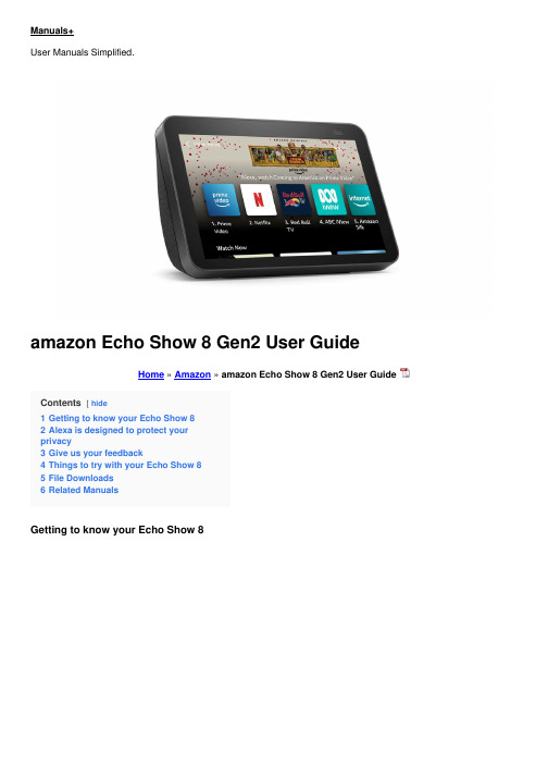
amazon Echo Show 8 Gen2 User GuideHome » Amazon » amazon Echo Show 8 Gen2 User GuideContents[ hideGetting to know your Echo Show 8Alexa is designed to protect yourAlexa is designed to protect your privacyWake word and indicatorsmesa doesn’t teg-J, ..rental your Echo device detects the wake word ! for 6,6 _le. ‘Alexa’). A blue light lets you know when audio is being sent to amazon’s secure cloud.Microphone and camera controlYou can election ally disconnect the mks and camera with the rums of a button. Slide the built-in cover to dose the camera.Voice historyWant to know exactly what Alexa heard? You can view and delete your voice recordings In the Alyea app at any time.These are just a few of the ways that you have transparency and control over your Alexa experience. Explore more at /alexaprivacy.1. Plugin your Echo Show 8Plug your Echo Show into an electrical socket using the included power adaptor. In about a minute, the display will turn on and Alexa will greet you.Amazon services Log vi with an existing Amazon account username and password, or create a new account.Installing the app on your phone or tablet helps you get more out of your Echo Show 8. It’s where you set up calling and messaging, manage music, lists, settings, and news.Swipe down from the top of the screen. or say ‘Alexa. show Settings’To access amazon User GuideEcho Show, Gen2, amazonRelated Manuals1. amazon Echo Show 8 User Manual2. Pair Bluetooth Speaker with Amazon Echo Show3. Amazon Echo User Guide4. Amazon Echo Buds User Guide5. i-box Portable Speaker Dock for Amazon Echo Dot User Guide Quick Start Guide Portable Speaker Dock for AmazonEcho Dot®...6. amazon Login with Amazon Getting Started Guide for Websites amazon Login with Amazon Getting Started Loginwith Amazon: Getting...。
8X8 DSP数字矩阵处理器说明书

8X8 DSP DIGITAL MATRIX PROCESSOR使用说明书User’s ManualEKX-8088X8数字矩阵处理器目 录产品功能 --------------------------------------------------1前面板说明 ------------------------------------------------1后背板说明 ------------------------------------------------2PC软件 ----------------------------------------------------2-3 PC软件说明 ------------------------------------------------4-9技术指标 --------------------------------------------------10配件清单 --------------------------------------------------10背板控制端口示意图 -----------------------------------------11-13 232通信协议控制代码 ----------------------------------------14-22使用安全事项 ----------------------------------------------23英文说明 --------------------------------------------------24-45●32位DSP芯片处理,96kHz采样率,24bit AD/DA转换。
●带有+48V幻象电源,话筒和线性输入增益切换,其中话筒的输入灵敏度可调。
●输入处理部分包含高切,低切,参量均衡,独立反馈抑制,噪声门,增益,静音,相位,连动调节,音、 量编组调节等处理功能。
SN65HVD08D中文资料

FEATURESAPPLICATIONSDESCRIPTIONV CCBAGNDD or P PACKAGE(TOP VIEW)LOGIC DIAGRAM (Positive Logic)DADERERBRemote(One of n Shown)SN75HVD08,SN65HVD08SLLS550A–NOVEMBER2002–REVISED MAY2003 WIDE SUPPLY RANGE RS-485TRANSCEIVERThe wide supply voltage range and low quiescentcurrent requirements allow the SN65HVD08s to •Operates With a3-V to5.5-V Supplyoperate from a5-V power bus in the cable with as •Consumes Less Than90mW Quiescent much as a2-V line voltage drop.Busing power in the Power cable can alleviate the need for isolated power to begenerated at each connection of a ground-isolated •Open-Circuit,Short Circuit,and Idle-Busbus.Failsafe Receiver•1/8th Unit-Load(up to256nodes on the bus)The driver differential outputs and receiver differentialinputs connect internally to form a differential in-•Bus-Pin ESD Protection Exceeds16kV HBMput/output(I/O)bus port that is designed to offer •Driver Output Voltage Slew-Rate Limited for minimum loading to the bus whenever the driver is Optimum Signal Quality at10Mbps disabled or not powered.The drivers and receivers •Electrically Compatible With ANSI TIA/EIA-485have active-high and active-low enables respectively,which can be externally connected together to func-Standardtion as a direction control.•Data Transmission With Remote StationsPowered From the Host•Isolated Multipoint Data Buses•Industrial Process Control Networks•Point-of-Sale Networks•Electric Utility MeteringThe SN65HVD08combines a3-state differential linedriver and differential line receiver designed for bal-anced data transmission and interoperation with ANSITIA/EIA-485-A and ISO-8482E standard-compliantdevices.Please be aware that an important notice concerning availability,standard warranty,and use in critical applications of TexasInstruments semiconductor products and disclaimers thereto appears at the end of this data sheet.These devices have limited built-in ESD protection.The leads should be shorted together or the device placed in conductive foam during storage or handling to prevent electrostatic damage to the MOS gates.ORDERING INFORMATIONover operating free-air temperature range unless otherwise noted(1)(2)(1)Stresses beyond those listed under"absolute maximum ratings”may cause permanent damage to the device.These are stress ratingsonly,and functional operation of the device at these or any other conditions beyond those indicated under"recommended operating conditions”is not implied.Exposure to absolute-maximum-rated conditions for extended periods may affect device reliability.(2)All voltage values,except differential I/O bus voltages,are with respect to network ground terminal.(3)Tested in accordance with JEDEC Standard22,Test Method A114-A.(4)Tested in accordance with JEDEC Standard22,Test Method C101.(1)The algebraic convention,in which the least positive(most negative)limit is designated as minimum is used in this data sheet.ELECTRICAL CHARACTERISTICS DRIVER SWITCHING CHARACTERISTICSSN75HVD08,SN65HVD08 SLLS550A–NOVEMBER2002–REVISED MAY2003over recommended operating conditions unless otherwise notedover recommended operating conditions unless otherwise notedRECEIVER SWITCHING CHARACTERISTICSPARAMETER MEASUREMENT INFORMATION0 or 3 V–7 V < V (test) < 12 VInputABV A V B V V OCV Input: PRR = 500 kHz, 50% Duty Cycle,t r <6ns, t f <6ns, Z O = 50 ΩL Instrumentation CapacitanceGenerator: PRR = 500 kHz, 50% Duty Cycle, t r <6 ns, t f <6 ns, Z o = 50 Ω3 V2 V –2 V C L = 50 pF ±20%C L Includes Fixture and Instrumentation CapacitanceSN75HVD08,SN65HVD08SLLS550A–NOVEMBER 2002–REVISED MAY 2003over recommended operating conditions unless otherwise notedFigure 1.Driver V OD With Common-Mode Loading Test CircuitFigure 2.Test Circuit and Definitions for the Driver Common-Mode Output VoltageFigure 3.Driver Switching Test Circuit and Voltage WaveformsR L = 110 Ω ± 1%Generator: PRR = 500 kHz, 50% Duty Cycle, t r <6 ns, t f <6 ns, Z o = 50 ΩOH≈ 0 VV O≈ 3 V0 VV OL Generator: PRR = 500 kHz, 50% Duty Cycle, t r <6 ns, t f<6 ns, Z o = 50 ΩΩ ≈3 V Generator: PRR = 500 kHz, 50% Duty Cycle, t r <6 ns, t f <6 ns, Z o = 50 Ω3 VV OHVOLC L = 15 pF ±20%C L Includes Fixture and Instrumentation Capacitance0 V SN75HVD08,SN65HVD08SLLS550A–NOVEMBER 2002–REVISED MAY 2003Parameter Measurement Information (continued)Figure 4.Driver High-Level Enable and Disable Time Test Circuit and Voltage WaveformsFigure 5.Driver Low-Level Output Enable and Disable Time Test Circuit and Voltage WaveformsFigure 6.Receiver Switching Test Circuit and Voltage WaveformsGenerator: PRR = 500 kHz, 50% Duty Cycle, t r <6 ns, t f <6 ns, Z o = 50 Ω0 V or 3 VA BD at 3 V S1 to B≈ V CCV OLD at 0 V S1 to ASN75HVD08,SN65HVD08SLLS550A–NOVEMBER 2002–REVISED MAY 2003Parameter Measurement Information (continued)Figure 7.Receiver Enable and Disable Time Test Circuit and Voltage Waveforms With Drivers EnabledGenerator: PRR = 100 kHz, 50% Duty Cycle, t r <6 ns, t f <6 ns, Z o = 50 ΩV A BA at 1.5 VB at 0 VS1 to BV OLV A at 0 V B at 1.5 V S1 to A ≈ V CCDEVICE INFORMATIONSN75HVD08,SN65HVD08SLLS550A–NOVEMBER 2002–REVISED MAY 2003Parameter Measurement Information (continued)Figure 8.Receiver Enable Time From Standby (Driver Disabled)Function TablesDRIVERRECEIVER(1)H =high level;L =low level;Z =high impedance;X =irrelevant;?=indeterminateEQUIVALENT INPUT AND OUTPUT SCHEMATIC DIAGRAMSSN75HVD08,SN65HVD08SLLS550A–NOVEMBER 2002–REVISED MAY 2003TYPICAL CHARACTERISTICS2.521.51D i f f e r e n t i a l O u t p u t V o l t a g e – V33.5DIFFERENTIAL OUTPUT VOLTAGEvsSUPPLY VOLTAGE4V CC – Supply Voltage – VI O – D r i v e r O u t p u t C u r r e n t – m ADRIVER OUTPUT CURRENTvsSUPPLY VOLTAGEV CC – Supply Voltage – V10.502.53.54.5L o g i c I n p u t T h r e s h o l d V o l t a g e – V1.52LOGIC INPUT THRESHOLD VOLTAGEvsSUPPLY VOLTAGE2.55.56.5V CC – Supply Voltage – V4060801001202.557.510Signaling Rate – MbpsRMS SUPPLY CURRENTvsSIGNALING RATEI C C – R M S S u p p l y C u r r e n t – m ASN75HVD08,SN65HVD08SLLS550A–NOVEMBER 2002–REVISED MAY 2003Figure 9.Figure 10.Figure 11.Figure 12.APPLICATION INFORMATIONOPTO-ISOLATED DATA BUSESSUPPLY SOURCE IMPEDANCEV S R LSN75HVD08,SN65HVD08SLLS550A–NOVEMBER 2002–REVISED MAY 2003As electrical loads are physically distanced from their power source,the effects of supply and return line Under dynamic load requirements,the distributed impedance and the resultant voltage drop must be inductance and capacitance of the power lines may accounted.If the supply regulation at the load cannot not be ignored and decoupling capacitance at the be maintained to the circuit requirements,it forces the load is required.The amount depends upon the use of remote sensing,additional regulation at the magnitude and frequency of the load current change load,bigger or shorter cables,or a combination of but,if only powering the SN65HVD08,a 0.1µF these.The SN65HVD08eases this problem by re-ceramic capacitor is usually sufficient.laxing the supply requirements to allow for more variation in the supply voltage over typical RS-485transceivers.Long RS-485circuits can create large ground loops and pick up common-mode noise voltages in excess of the range tolerated by standard RS-485circuits.A In the steady state,the voltage drop from the source common remedy is to provide galvanic isolation of the to the load is simply thewire resistance times the data circuit from earth or local grounds.load current as modeled in Figure 13.Transformers,capacitors,or phototransistors most often provide isolation of the bus and the local node.Transformers and capacitors require changing signals to transfer the information over the isolation barrier and phototransistors (opto-isolators)can pass steady-state signals.Each of these methods incurs additional costs and complexity,the former in clock encoding and decoding of the data stream and the latter in requiring an isolated power supply.Quite often,the cost of isolated power is repeated at Figure 13.Steady-State Circuit Modeleach node connected to the bus as shown in Fig-ure 14.The possibly lower-cost solution is to gener-For example,if you were to provide 5-V ±5%supply ate this supply once within the system and then power to a remote circuit with a maximum load distribute it along with the data line(s)as shown in requirement of 0.1A (one SN65HVD08),the voltage Figure 15.at the load would fall below the 4.5-V minimum of most 5-V circuits with as little as 5.8m of 28-GA conductors.Table 1summarizes wire resistance and the length for 4.5V and 3V at the load with 0.1A of load current.The maximum lengths would scale linearly for higher or lower load currents.Table 1.Maximum Cable Lengths for MinimumLoad Voltages at 0.1A LoadFigure 14.Isolated Power at Each NodeAN OPTO ALTERNATIVE“1”+5 VSN75HVD08,SN65HVD08SLLS550A–NOVEMBER 2002–REVISED MAY 2003The ISO150is a two-channel,galvanically isolated data coupler capable of data rates of 80Mbps.Each channel can be individually programmed to transmit data in either direction.Data is transmitted across the isolation barrier by coupling complementary pulses through high-voltage 0.4-pF capacitors.Receiver circuitry restores the pulses to standard logic levels.Differential signal transmission rejects isolation-mode voltage transients up to 1.6kV/ms.ISO150avoids the problems commonly associated with opto-couplers.Optically-isolated couplers require high current pulses and allowance must be made for LED aging.The ISO150's Bi-CMOS circuitry operates at 25mW per channel with supply voltage range matching that of the SN65HVD08of 3V to 5.5V.Figure 16shows a typical circuit.Figure 15.Distribution of Isolated Power The features of the SN65HVD08are particularly good for the application of Figure 15.Due to added supply source impedance,the low quiescent current require-ments and wide supply voltage tolerance allow for the poorer load regulation.Figure 16.Isolated RS-485Interface11元器件交易网IMPORTANT NOTICETexas Instruments Incorporated and its subsidiaries (TI) reserve the right to make corrections, modifications, enhancements, improvements, and other changes to its products and services at any time and to discontinue any product or service without notice. Customers should obtain the latest relevant information before placing orders and should verify that such information is current and complete. All products are sold subject to TI’s terms and conditions of sale supplied at the time of order acknowledgment.TI warrants performance of its hardware products to the specifications applicable at the time of sale in accordance with TI’s standard warranty. T esting and other quality control techniques are used to the extent TI deems necessary to support this warranty. Except where mandated by government requirements, testing of all parameters of each product is not necessarily performed.TI assumes no liability for applications assistance or customer product design. Customers are responsible for their products and applications using TI components. T o minimize the risks associated with customer products and applications, customers should provide adequate design and operating safeguards.TI does not warrant or represent that any license, either express or implied, is granted under any TI patent right, copyright, mask work right, or other TI intellectual property right relating to any combination, machine, or process in which TI products or services are used. Information published by TI regarding third-party products or services does not constitute a license from TI to use such products or services or a warranty or endorsement thereof. Use of such information may require a license from a third party under the patents or other intellectual property of the third party, or a license from TI under the patents or other intellectual property of TI.Reproduction of information in TI data books or data sheets is permissible only if reproduction is without alteration and is accompanied by all associated warranties, conditions, limitations, and notices. Reproduction of this information with alteration is an unfair and deceptive business practice. TI is not responsible or liable for such altered documentation.Resale of TI products or services with statements different from or beyond the parameters stated by TI for that product or service voids all express and any implied warranties for the associated TI product or service and is an unfair and deceptive business practice. TI is not responsible or liable for any such statements. Following are URLs where you can obtain information on other Texas Instruments products and application solutions:Products ApplicationsAmplifiers Audio /audioData Converters Automotive /automotiveDSP Broadband /broadbandInterface Digital Control /digitalcontrolLogic Military /militaryPower Mgmt Optical Networking /opticalnetwork Microcontrollers Security /securityTelephony /telephonyVideo & Imaging /videoWireless /wirelessMailing Address:Texas InstrumentsPost Office Box 655303 Dallas, Texas 75265Copyright 2004, Texas Instruments Incorporated。
RGB-Link X8C005用户手册说明书
用户手册目录目录 (1)声明 (2)声明/担保与赔偿 (2)声明 (2)担保与赔偿 (2)安全操作概要 (2)请勿开盖 (2)正确使用电源 (2)正确接地 (2)使用适当的电源线 (3)使用适当的保险丝 (3)远离易燃易爆危险物品 (3)安装安全概要 (3)第1章产品简介 (1)1.1随附配件 (1)1.2产品概述 (2)1.2.1后面板 (3)1.2.2前面板 (4)1.2.3外形尺寸图 (5)第2章产品安装 (6)2.1插入信号源 (6)2.2插入电源 (6)2.3设备上电 (6)第3章产品使用 (7)3.1安装XPOSE软件 (7)3.2XPOSE2.0控制X8 (10)3.2.1登录软件 (10)3.2.2输入输出设置 (10)3.2.3显示管理 (17)3.2.4图层管理 (24)3.2.5场景管理 (28)3.2.6系统设置 (32)第4章订购编码 (36)4.1产品编码 (36)4.2模块编码 (36)4.2.1输入模块 (36)4.2.2输出模块 (36)4.2.3其他 (36)第5章技术支持 (37)5.1联系我们 (37)第6章附录 (38)6.1规格 (38)6.2术语和定义 (39)6.3修订记录 (45)首先感谢您选购我们的产品!为了让您迅速掌握如何使用这款视频处理器,我们为您送上了详细的产品使用手册。
您可以在使用视频处理器之前阅读产品介绍以及使用方法,请仔细阅读我们所提供给您的所有信息,以便于您正确地使用我们的产品。
声明声明/担保与赔偿声明该设备经过严格测试,符合电子类数码设备的标准,根据FCC第15部分的规定,这些限制是为了合理地防止设备在商业环境中操作时的有害干扰。
如果没有安装和使用规定的指导手册,该设备的产生、使用和放射无线电频率,可能会对无线电通讯造成有害干扰。
闲杂人员若擅自操作造成伤害,将自行负责!担保与赔偿视诚提供了作为法定保障条款组成部分,与完善生产相关的保证书。
H型钢参数特性

H型钢、H型钢桩的规格标识表记标帜采取:高度H×宽度B×腹板厚度t1×翼缘厚度t2暗示.H
340×250×9×14之杨若古兰创作
剖分T型钢的规格标识表记标帜采取:高度h ×宽度B ×腹板厚度t1×翼缘厚度t2暗示.T 248×199×9×14
GB/T 11263-1998
GB/T 11263-1998
GB/T 11263-1998
(1)分类和代号.
表1 热轧H型钢和剖分T型钢的分类和代号
(2)尺寸规格见表2~表4.
(3)答应偏差见表5~表8
表2 宽、中、窄翼缘H型钢的尺寸规格H—高度 B—宽度 t1—腹板厚度 t2—翼缘厚度 r—
圆角半径
注:1.“#”暗示的规格为非经常使用规格.
2.“*”暗示的规格,目前国内尚未生产.
3.型号属同一范围的产品,其内侧尺寸高度是分歧的.
4.截面面积计算公式为“t1(H~2t2)+2Bt2+O.858 r2.”
表3 H型钢桩的尺寸规格
H—高度 B—宽度 t1—腹板厚度 t2—翼缘厚度 r—
圆角半径
注:1.“*”暗示的规格,目前国内尚未生产.
2.型号属同一范围的产品,其内侧尺寸高度是分歧的.
3.截面面积计算公式为“t1(H-2t2)+2Bt2+0.858 r²”.
表4 剖分T型钢的尺寸规格
h—高度 B—宽度 t1—腹板厚度 t2—翼缘厚
度 Cx—重心 r—圆角半径
注:“#”暗示的规格为非经常使用规格.。
彩讯 TMX-RGB 系列矩阵切换器 说明书
TMX-RGB系列矩阵切换器感谢您使用北京彩讯科技有限公司产品!—— 为了您和设备的安全,请您务必在使用前阅读下页的安全说明。
—— 如果在使用中遇到疑问,请首先阅读说明书。
正文中有设备操作的详细描述。
如果仍有疑问,请联系我们,我们将尽快给您满意的答复。
—— 本手册如有版本变动,恕不另行通知,请谅解。
手册中使用的图标说明:—— 警告,所述文字涉及危险或危害。
—— 提示,附加的说明或有帮助的技巧。
—— 注解,对文字含义的说明。
安全说明电源 ——请使用带保护地的单相三线制电源,并确保整个系统使用同一保护地。
不能使用无保护地的电源,电源线的接地脚不能破坏。
断电 ——需要进行设备移动或其他需要断电的工作时,要关断所有的电源,包括关断外部电源插座,拔掉电源插头,以确保您的安全。
线缆 ——不能在电源线、信号线、通讯线等线缆上压放物品,应避免线缆被践踏或挤压,以防止出现漏电或短路等危险。
信号线连接 ——从设备上插、拔信号线时,设备需要断电,以免击穿电路。
带电插拔造成的损坏不在保修范围。
散热孔 ——设备箱盖和箱底可能有散热用的开孔,不要堵塞这些开孔,以防热量积聚,损坏设备。
设备固定 ——合理固定设备,确保设备放置合适并且稳固,防止设备跌落。
环境 ——设备工作的环境要注意防尘、防潮。
维修 ——所有的维修应交给专业维修人员完成,不要尝试自己维修设备。
为防止电击危险,不要擅自打开箱盖。
一、 概述彩讯科技TMX-RGB 系列矩阵切换器是对RGBHV 或HDTV 信号进行切换和分配的切换设备,它可同时将多路RGBHV 输入信号分别切换到任何一个或多个输出通道。
该设备具有断电现场保护功能,能保存设备关机前的工作状态,具备与计算机联机使用的RS-232通讯接口,并提供通讯协议和演示程序,方便联机使用。
表A 列出了现在本系列所包含的七款矩阵切换器。
本产品广泛应用于需要切换和选择RGBHV 信号的各类场合,如:广播电视、大屏幕投影电视、电化教育、电视电话会议、多媒体会议室等。
h2jtfg8yd3mbr参数

h2jtfg8yd3mbr参数H2JTFG8YD3MBR参数使用指南什么是H2JTFG8YD3MBR参数H2JTFG8YD3MBR参数是一种神秘的编码方式,常用于某些系统的配置文件中。
它的具体含义和用途因系统而异,通常需要根据具体的上下文进行解读。
H2JTFG8YD3MBR参数的特点•随机性强:H2JTFG8YD3MBR参数是由随机字符和数字组成的,每个参数都是唯一的。
•长度固定:H2JTFG8YD3MBR参数的长度通常是固定的,一般为10个字符。
•密钥保密性:H2JTFG8YD3MBR参数通常用于敏感信息的传递,因此应该保证参数的保密性。
如何使用H2JTFG8YD3MBR参数1.解析参数含义:根据具体的系统和使用场景,需要查找相关的文档或者咨询开发人员,以了解H2JTFG8YD3MBR参数的含义和用法。
2.配置参数:将解析出的含义和用法,按照系统要求进行配置。
通常可以在系统配置文件中找到相应的位置进行设置。
3.保护参数安全:由于H2JTFG8YD3MBR参数常用于敏感信息的传递,因此在使用过程中需要注意保护参数的安全性。
可以采用加密方式存储参数,限制访问权限等措施来保护参数的安全。
注意事项•H2JTFG8YD3MBR参数是系统特定的参数,不同系统的参数可能不一样,不能通用使用。
•在使用H2JTFG8YD3MBR参数时,需要遵循相关系统的规定和要求,不可随意更改或错误使用。
•在解析H2JTFG8YD3MBR参数时,如果遇到困难或有疑问,建议及时与系统开发人员或技术支持人员取得联系。
结语H2JTFG8YD3MBR参数作为一种常见的编码方式,在某些系统中广泛使用。
正确理解和使用H2JTFG8YD3MBR参数对于系统的稳定性和安全性具有重要意义。
希望本文对你在使用H2JTFG8YD3MBR参数时有所帮助!H2JTFG8YD3MBR参数使用指南(续)H2JTFG8YD3MBR参数的使用场景•数据库配置:H2JTFG8YD3MBR参数常用于数据库连接配置,包括服务器地址、用户名、密码等敏感信息的传递。
Ambion Lambda HindIII dsDNA Markers说明书

Catalog #:AM7720Lambda HindIIIdsDNA MarkersStore at –20°C.Do not store in a frost-free freezer.Catalog # (P/N):AM7720Amount:200μgConcentration:0.5 mg/mLStorage Conditions:Store at –20°C. This product is shipped at ambient temperature. This in no way affects its high-quality performance.Upon receipt, store at –20°C. Avoid multiple free z e-thaw cycles.Do not store in a frost-free freezer.Aliquots of theproduct may be stored short-term at 4°C.Storage Buffer:10 mM Tris (p H 7.5), 1 mM ED TAUSER INFORMATIONProduct Description:Lambda H indIII DN A Mar k ers provide a set of double-stranded DN A si z e standards, 23130 bp, 9416 bp, 6557 bp,4361 bp, 2322 bp, 2027 bp, 564 bp and 125 bp in length.Applications:Lambda H indIII DN A Mar k ers are intended for use as si z e mar k ers for agarose gel electrophoresis. They can bevisuali z ed after electrophoresis by ethidium bromide staining and U V fluorescence, or they can be 5' end-labeledusing K lenow P olymerase or T4 P olynucleotide K inase for visuali z ation by autoradiography. Typically, 7–8 bandscan be visuali z ed on an agarose gel (see F igure 1).Ethidium Bromide StainingThe mar k ers may be visuali z ed by several methods.A.Add ethidium bromide to the sample at 10–50μg/mL final concentration before loading.B.Incorporate ethidium bromide into the gel or running buffer at 0.5μg/mL.C.Stain post-electrophoresis using 0.5μg/mL ethidium bromide in gel running buffer (e.g., 1μL of 10 mg/mLethidium in 20 mL of buffer).Note:F or methods B or C, destain for 5–10 min in buffer without ethidium bromide.End Labeling with [α-32P]dNTP and K lenow Pol y meraseF or a 20μL end-labeling reaction, use the following reaction conditions.200 mM HEPE S (p H 7.2)Citrate10 mM N a310 mM MgCl21 mM D TT50μM each of 3 d N T P s (i.e., either no dAT P or no dCT P)5μM unlabeled form of the radiolabeled d N T P10–20μCi (3000 Ci/mmol) of [α-32P]d N T P, either dAT P or dCT P(equivalent to 0.2–0.3μM)<0.5μg ds DN A Mar k er3 U K lenow polymerase1.Incubate at 37°C for 15 min.2.Add 100μL T E.e labeled mar k ers directly by adding an equal volume of G el Loading Buffer II (P/N AM8546G), heating to65°C for 10 min, and loading on the gel.End Labeling with T4 Pol y nucleotide K inase (PN K) and [γ-32P]ATPW e recommend using the Ambion®K inaseMa x™K it (P/N AM1520). The standard protocol calls fordephosphorylation of the DN A, using al k aline phosphatase, and removal of the al k aline phosphatase, using theP hosphatase R emoval R eagent provided with the k it, before performing a forward polynucleotide k inase reaction(PNK cataly z es the transfer of theγphosphate from [γ-32P]AT P to the 5'-OH created by al k aline phosphatase).Al k aline phosphatase can also be removed by phenol e x traction followed by ethanol precipitation.5' end-e x change reactions are possible using the K inaseMa x K it and DN A which has not been dephosphorylated(i.e., contains 5' phosphate).W hile labeling by 5' end-e x change is 1/5 as efficient as a PNK forward reaction, thespecific activity of the probe will be high enough for use on do z ens of lanes, and the reaction is quic k er and easier.Use labeled mar k ers directly by adding an equal volume of G el Loading Buffer II (P/N AM8546G), heating to 65°C for10 min and loading on the gel.(Optional) Remo v al of Unincorporated Radiolabeled Nucleotides from End-labeled Products b yPrecipitationO Ac to a final concentration of 0.5 M.1.Add NH42.Add 2.5 volumes of ethanol.3.Chill at –20°C for 20 min and centrifuge for 10 min.4.Carefully decant and discard supernatant using appropriate disposal techniques.5.Add 100μL of T E and 100μL of G el Loading Buffer II.6.H eat aliquots to 65°C for 10 min before loading.V isuali z ation b y Autoradiograph yAn aliquot of 1 x 10⁵cpm of32P-labeled mar k er (generally 1–2μL) typically generates bands visible with a 2 hourautoradiograph. As the32P decays, larger volumes can be used.Figure 1.0.5μg of Lambda Hin d III DN A Mar k ers were run on a 1% nativeagarose gel until the bromophenol blue dye was 3/4 down the gel, thenstained with ethidium bromide.Q UALIT Y CONTROLFunctional Testing:Lambda H indIII DN A Mar k ers are separated on a 1% native agarose gel. All bands are sharp and intact.OTHER INFORMATIONMaterial Safet y Data Sheets:Material Safety D ata Sheets (MS D Ss) can be printed or downloaded from product-specific lin k s on our website at the followingaddress: /techlib/msds. Alternatively, e-mail your request to MS D S_Inquiry_CC R***********************.Specify the catalog or part number(s) of the product(s), and we will e-mail the associated MS D Ss unless you specify a preference forfa x delivery. F or customers without access to the internet or fa x, our technical service department can fulfill MS D S requests placed bytelephone or postal mail. (R equests for postal delivery require 1–2 wee k s for processing.)W arrant y and Liabilit y:For research use only. Not for use in diagnostic procedures.Applied Biosystems is committed to delivering superior product quality and performance, supported by industry-leading global serviceand technical support teams. W arranty information for the accompanying consumable product is available at/info/warranty in "Limited W arranty for Consumables," which is sub j ect to the e x clusions, conditions, e x ceptions,and limitations set forth under the caption“EX CLUSI ON S, C OND ITI ON S, EX C EP TI ON S, A ND LIMITATI ON S”in the full warrantystatement. P lease contact Applied Biosystems if you have any questions about our warranties or would li k e information aboutpost-warranty support.Information in this document is sub j ect to change without notice. Applied Biosystems assumes no responsibility for any errors thatmay appear in this document.Applied Biosystems disclaims all warranties with respect to this document, e x pressed or implied, including but not limited to those ofmerchantability or fitness for a particular purpose. In no event shall Applied Biosystems be liable, whether in contract, tort, warranty,or under any statute or on any other basis for special, incidental, indirect, punitive, multiple or consequential damages in connectionwith or arising from this document, including but not limited to the use thereof.Trademarks, Patents, and Licensing:Applied Biosystems, AB (D esign), and Ambion are registered trademar k s, and K inaseMa x is a trademar k of Applera Corporation or its subsidiaries in the US and/or certain other countries. All other trademar k s are the sole property of their respective owners.©2008 Ambion, Inc. All rights reserved. 4386529A。
Hooks 8, 8X, 88X 产品说明书

ContentsIntended Use . . . . . . . . . . . . . . . . . . . . . . . . . . . . . . . . . . . . . . . . . . . . . . . . . . . . . . . . . . . . . . . .3 Warnings and Precautions . . . . . . . . . . . . . . . . . . . . . . . . . . . . . . . . . . . . . . . . . . . . . . . . . . . .3 Qualified Provider . . . . . . . . . . . . . . . . . . . . . . . . . . . . . . . . . . . . . . . . . . . . . . . . . . . . . . . . . . .4 Specifications and Preparations Before Use(Risk Management for Installation and Calibration) . . . . . . . . . . . . . . . . . . . . . . . . . . . . . . .4 Compatibility . . . . . . . . . . . . . . . . . . . . . . . . . . . . . . . . . . . . . . . . . . . . . . . . . . . . . . . . . . . . . . . .5 Disposal / Waste Handling . . . . . . . . . . . . . . . . . . . . . . . . . . . . . . . . . . . . . . . . . . . . . . . . . . . .5 Warranty . . . . . . . . . . . . . . . . . . . . . . . . . . . . . . . . . . . . . . . . . . . . . . . . . . . . . . . . . . . . . . . . . . .5 User Instructions . . . . . . . . . . . . . . . . . . . . . . . . . . . . . . . . . . . . . . . . . . . . . . . . . . . . . . . . . . . .6 Serious Incidents . . . . . . . . . . . . . . . . . . . . . . . . . . . . . . . . . . . . . . . . . . . . . . . . . . . . . . . . . . . .6To see other language options, visit .2Intended UseThe Model 8, 8X, and 88X are prosthetic terminal devices that are commonly referred to as “canted split hooks” and are used to provide for both fine prehension and gross grasping of objects when controlled through a cable that is operated with body motions. These hooks are a voluntary-opening device and grasping tension is adjusted by the adding of tension bands, rings, or springs (see catalog for additional information). There are also smaller sizes available; see for information on other sizes of canted hooks.Performance CharacteristicsSize Medium Adult Medium Adult Medium AdultLength 4.625 in.(11.7 cm)4.625 in.(11.7 cm)4.625 in.(11.7 cm)Weight8 oz. (227 g)7.5 oz. (213 g) 4 oz. (113 g) Material Stainless Steel Stainless Steel AluminumGrip Serrated Surface Nitrile Lined Nitrile LinedThese devices are intended for single patient use only.Storage and HandlingIt is recommended that prosthetic hooks (or prosthetic/orthotic components) be stored in a cool, clean, dry environment away from harsh chemicals (chlorine, acids, acetone, etc.).Warnings and PrecautionsCAUTION: Nitrile coatings are not intended for use in high temperatureapplications. Refrain from contact with items that are above 85 °C (185 °F)as damage to the coating may occur.NOTICE: An upper-limb prosthetic device user’s ability to drive should bedetermined on a case-by-c ase basis by a specialist. Contact your localgoverning authorities regarding any driving restrictions or limitations.WARNING: Body-powered devices should not rely on cable tension forgrasp control if the user has been cleared to drive with the prosthesis.3Failure to maintain tension while controlling the steering wheel couldcause serious injury or death.CAUTION: Abnormal or improper environmental conditions will leadto malfunctioning and damage of the prosthesis and are not coveredunder the warranty of the device. This prosthetic component must notbe subjected to dust/debris, liquids other than fresh water, abrasives,vibration, activities which would damage the biological limb, or prolongedextreme temperatures (< -5 °C or > 50 °C). Do not allow debris or liquids toremain in the prosthesis and its components during use. Rinse the devicewith fresh water and dry immediately after exposure.CAUTION: The hook is waterproof to 1 meter. However, if the hook issubmerged, it should be rinsed with fresh water and dried immediately toremove salt, chlorine, or debris.Qualified ProviderAttachment, adjustment, alignment, and delivery of this device must be performed by or under the direct supervision of a qualified prosthetist. Unless stated in this manual, any such activities should not be attempted by the user and will potentially void the device warranty.Specifications and Preparations Before Use (Risk Management for Installationand Calibration)InstallationThe hook may be installed in any Fillauer wrist unit with a ½-20 thread. Follow the instructions provided with the wrist unit for best results.CablingThe hook “thumb” has been designed with a receiver for a ⁹⁄³² inch ball terminal. A triple swivel with ⁹⁄³² inch ball terminal should be selected with a cable connection that matches the cable used in the prosthesis. Cable routing should ensure a direct line of 4pull that minimizes bends in the cable, otherwise excess cable friction or failure could result .Adding Tension to Hook GraspTo add more force to the grasp of the hook, additional tension bands may be applied using the E-Z Hook Tension Band Applier (55144) or similar device. Additional bands are included with the hook and are available in beige (53869) or black (53869-BLK). For greater tension, hook rings (57500) or stainless-steel tension springs (55363) may be used. Tension springs are recommended for situations where chemical or heat exposure could cause band or ring failure.CompatibilityFillauer hooks have been tested with and are recommended for use with Fillauer wrists that have a ½-20 internal thread. They may be used with any equivalent ½-20 threaded wrist units; however, damage caused by other manufacturers wrist units is not covered under warranty of this device.Only Fillauer tension bands, hook rings, and tension springs may be used with Fillauer hooks to adjust the grasping force of the hook.Disposal / Waste HandlingThe product must be disposed of in accordance with applicable local laws and regulations. If the product has been exposed to bacteria or other infectious agents,it must be disposed of in accordance with applicable laws and regulations for the handling of contaminated material.All metal components may be removed and recycled at the appropriate recycling facility.WarrantyThis product has an 18-month warranty against manufacturer defects.5User InstructionsThe providing health care professional must review the following information directly with the user.Care and MaintenanceCAUTION: Nitrile coatings are not intended for use in high-temperatureapplications. Refrain from contact with items that are above 85 °C (185 °F)as damage to the coating may occur.NOTICE: Nitrile coatings are expected to wear under normal use. Thecoating can be replaced but is not covered under warranty, except formanufacturer defect.NOTICE: An upper-limb prosthetic device user’s ability to drive shouldbe determined on a case-by-case basis by a specialist. Contact your localgoverning authorities regarding any driving restrictions or limitations.WARNING: Body-powered devices should not rely on cable tension forgrasp control if the user has been cleared to drive with the prosthesis.Failure to maintain tension while controlling the steering wheel couldcause serious injury or death.CAUTION: Abnormal or improper environmental conditions will leadto malfunctioning and damage of the prosthesis and are not coveredunder the warranty of the device. This prosthetic component must notbe subjected to dust/debris, liquids other than fresh water, abrasives,vibration, activities which would damage the biological limb, or prolongedextreme temperatures (< -5 °C or > 50 °C). Do not allow debris or liquids toremain in the prosthesis and its components during use. Rinse the devicewith fresh water and dry immediately after exposure.CAUTION: The hook is waterproof to 1 meter. However, if the hook issubmerged, it should be rinsed with fresh water and dried immediately toremove salt, chlorine, or debris.6Serious IncidentsIn the unlikely event of a serious incident, seek immediate medical help and contact your prosthetist at your earliest possible convenience. Clinicians should contact their local Fillauer representative immediately in the event of any device failure. Fillauer LLC2710 Amnicola Highway Chattanooga, TN 37406 423.624.0946Fillauer EuropeKung Hans väg 2192 68 Sollentuna, Sweden +46 (0)8 505 332 00© 2021 Fillauer LLCM085/10-06-21/Rev.1。
电子工厂常用物料编码规范
物料编码规X1. X围本规X规定了##电子技术##在采购、生产、仓管中所有物料的编码规那么。
本规X适用于##电子技术##。
新增物料的引用都必须遵守此规X。
2. 概述物料编码是以简单的文字符号或数字来代表物料的品名、规格或类别与其它有关事项的一种管理工具。
本规X的目的是便于物料的采购、跟催、验收、查询、领发、盘点、储存等工作,物料的电脑化管理,使各部门提高工作效率。
3. 编码原那么物料编码必须遵守物料编码的原那么,合理的物料编码,必须具备以下根本条件:3.1.唯一性:是指一个物料编码只能代表一种物料,同一种物料只能找到一个物料编码,而绝无一种物料有数个物料编码,或一个物料编码有数种物料。
3.2.简单性:编码的目的在于将物料化繁为简,便于物料的管理,因此物料编码在应用文字符号或数字上应力求简单明了,这样可节省阅读、填写、录入的时间,并可减少其中的错误机会。
3.3.完整性:在物料编码时,所有的物料都应有物料编码可归,这样的物料编码才能完整。
假设某些物料找不到赋予的物料编码,那么物料编码缺乏完整性。
3.4.伸缩性:物料编码要考虑到未来新产品开展和产品规格的变更而发生物料扩展或变动的情形。
4. 名词术语成形:施加一外力,改变元件引线的走向或直径,使之形成所要求的几何形状。
5. 编码规定本编码系统格式根本由分类码、规格码、附属码与供给商区分码四局部组成,力求尽可能反响物料的特征。
分类码包括大分类、小分类代码;规格码包含物料的规格、属性;附属码是便于区分同种物料不同状态〔如成形、封装等〕;最后一位〔X〕当供给商需要加以区别时进展顺序编码,不用区别时以“0〞编码。
为了表达物料编码的唯一性,一般采用重新编码加以区分不同的供给商或同一物料不同版本的情况。
编码采用24个大写英文字母〔I 、O 除外,防止与数字1、0混淆〕与阿拉伯数字0~9混合使用,固定长度12位。
6. 编码方法本编码系统主要采用暗示编码法〔即从编码中可以获取物料的相关信息〕。
sn65hvd234

• • • • • • • • •
These devices have limited built-in ESD protection. The leads should be shorted together or the device placed in conductive foam during storage or handling to prevent electrostatic damage to the MOS gates.
Copyright © 2002–2008, Texas Instruments Incorporated
PRODUCTION DATA information is current as of publication date. Products conform to specifications per the terms of the Texas Instruments standard warranty. Production processing does not necessarily include testing of all parameters.
DESCRIPTION (CONTINUED)
If the common-mode range is restricted to the ISO-11898 Standard range of –2 V to 7 V, up to 120 nodes may be connected on a bus. These transceivers interface the single-ended CAN controller with the differential CAN bus found in industrial, building automation, and automotive applications. The RS, pin 8 of the SN65HVD233, SN65HVD234, and SN65HVD235 provides for three modes of operation: high-speed, slope control, or low-power standby mode. The high-speed mode of operation is selected by connecting pin 8 directly to ground, allowing the driver output transistors to switch on and off as fast as possible with no limitation on the rise and fall slope. The rise and fall slope can be adjusted by connecting a resistor to ground at pin 8, since the slope is proportional to the pin's output current. Slope control is implemented with a resistor value of 10 kΩ to achieve a slew rate of 915 V/µs and a value of 100 kΩ to achieve 9 2.0 V/µs slew rate. For more information about slope control, refer to the application information section. The SN65HVD233, SN65HVD234, and SN65HVD235 enter a low-current standby mode during which the driver is switched off and the receiver remains active if a high logic level is applied to pin 8. The local protocol controller reverses this low-current standby mode when it needs to transmit to the bus. A logic high on the loopback LBK pin 5 of the SN65HVD233 places the bus output and bus input in a high-impedance state. The remaining circuit remains active and available for driver to receiver loopback, self-diagnostic node functions without disturbing the bus. The SN65HVD234 enters an ultralow-current sleep mode in which both the driver and receiver circuits are deactivated if a low logic level is applied to EN pin 5. The device remains in this sleep mode until the circuit is reactivated by applying a high logic level to pin 5. The AB pin 5 of the SN65HVD235 implements a bus listen-only loopback feature which allows the local node controller to synchronize its baud rate with that of the CAN bus. In autobaud mode, the driver's bus output is placed in a high-impedance state while the receiver's bus input remains active. For more information on the autobaud mode, refer to the application information section. AVAILABLE OPTIONS (1)
swrh 82 dh 材料标准
swrh 82 dh 材料标准
SWRH 82 DH是一种碳素结构钢,符合日本工业标准JIS G3506。
SWRH代表着碳素结构钢丝的材料代码,而82代表着该钢的碳含量
为0.80%,DH表示该钢经过冷加工后的状态。
根据JIS G3506标准,SWRH 82 DH钢材通常用于制造弹簧和其
他弹性零件。
它具有良好的强度和韧性,适用于要求高强度和耐磨
性的应用。
在制造过程中,通常会进行冷加工处理,以提高钢材的
强度和硬度。
此外,根据标准,SWRH 82 DH钢材的化学成分、机械性能和加
工性能都有严格的要求。
具体的化学成分包括碳、硅、锰等元素的
含量,机械性能包括抗拉强度、屈服强度、延伸率等指标。
加工性
能则包括冷弯性能、冷加工硬化性能等。
总的来说,SWRH 82 DH钢材是一种高强度、高韧性的碳素结构钢,符合JIS G3506标准,适用于制造弹簧和其他弹性零件,具有
严格的化学成分、机械性能和加工性能要求。
- 1、下载文档前请自行甄别文档内容的完整性,平台不提供额外的编辑、内容补充、找答案等附加服务。
- 2、"仅部分预览"的文档,不可在线预览部分如存在完整性等问题,可反馈申请退款(可完整预览的文档不适用该条件!)。
- 3、如文档侵犯您的权益,请联系客服反馈,我们会尽快为您处理(人工客服工作时间:9:00-18:30)。
服务类的个人独资企业怎么享受核定征收5%
中国是贸易大国,国家主要的GDP是依靠贸易行业提供的,随着社会的发展,第三产业服务行业在中国的发展趋势也日渐明显,服务行业在中国的地位也越来越明显,因
为随着社会经济的发展,服务业肯定是大趋势。
在互联网和实体经济接触的这个时候,比如阿里巴巴这样的企业就能很快的发展。
对于服务行业小编的税收洼地可以有很多
的税收筹划方式。
可以给企业享受核定征收。
在税收洼地有一种企业形式是个人独资企业,这种企业形式不需要缴纳企业所得税,
只用上交个人经营所得的个人所得税,按照五级累进制计算5%-35%,服务行业核定
开票额的10%作为企业的利润,企业所得税收缴纳实际利率为开票额的0.5%-3.1%,具体如开票100万核定税率为1.94%,200万核定税率为2.66%,300万核定征收为2.91%400万核定征收为3.03% ,500万为3.1%
增值税部分个人独资企业为小规模3%,可以开增值税专用发票3%的抵扣,也可以开普票,享受地方留存50%-70%的奖励以后企业纳税为开票额的2.25%,附加税为增
值税的12%开票额的0.36%附加税部分不奖励。
综上个人独资企业综合税率为5.71%(小规模服务行业)及企业缴纳五点几个点的税金以后这笔资金就可以自由的使用。
需要税收优惠政策可以联系范老师 I52-I33-O6641
企业可以通过办理服务类型的个人独资企业和主体公司发生业务来往,转移利润到个
人独资企业,享受这部分利润的核定征收。
办理比较多的个人独资企业服务行业是,
技术服务,技术推广,软件开发,企业管理,企业营销策划,咨询服务类的个人独资
企业,具体还看根据企业的情况而定,如果本身是服务行业的需要这类业务就比较多,如果本身不是服务行业,是贸易行业或者制造业那么企业需要这类的服务就比较少,
能转移享受核定的利润就不多。
那么小编给您介绍我们税收洼地的另外一种税收政策,针对有限公司的奖励政策。
1.增值税奖励地方留存的50%-70%(地方留存总增值税50%)企业上交100万的增
值税财政会在次月奖励给企业25万-35万。
贸易行业16%的增值税压力比较大的就比较适合。
2.企业所得税奖励给企业地方留存的50%-70%(地方留存总企业所得税40%)企业上交100万的企业所得税财政次月会奖励给企业20万-28万
3.纳税以后财政这块次月直接奖励,不需要企业在对财政进行申请奖励。
小编所在税
收洼地属于开发区经济条件贫困,办公条件差不好吸引人才,所以当时实行的是总部
经济招商形式,不需要企业实体办公,注册地址在税收洼地就可以办公地址可以选在
一线二线城市。
企业的办理也非常方便,小编的公司提供办理和后续的代账服务,核名——工商——国地税报道——银行开户——核定流程,都非常的方便,企业如果方便可以到当地办理工商出营业执照时需要法人身份证原件,银行开户的时候需要法人到场(或者委托我们代办)费用3000元一家企业,后期的代账服务是小规模企业300/月一般纳税人500元/月。
代开银行账户1000元/家。
