ST系列止动气缸
ST系列止动气缸
气动执行元件
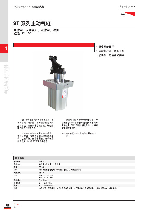
ST 系列止动气缸New
单作用(后弹簧),双作用,磁传
缸径 32,50
系列止动气缸常用于流水线上工
件的阻挡。
气缸伸出时可把流水线上的
工件挡住,而无须停止流水线;气缸缩
回时物件可继续传送。
该系列止动气缸采用紧凑型设计,
法兰式安装,活塞杆端部为滚轮杠杆结
构,止动平稳,无冲击震动。
有单作用
50 两种缸径可选。
紧凑型单作用(后弹簧),双作用PT 1/8 阳极氧化铝合金缸筒,镀铬钢活塞杆,丁腈橡胶密封件法兰式缸径 32:20 mm 缸径 50:30 mm 0 ~ 60°C 0.1 ~ 0.85 MPa 50 ~ 700 mm/sec 洁净空气,不需润滑。
如果使用了油雾润滑,应不间断的使用油雾润滑。
(建议使用镀铬钢活塞杆
»»滚轮杠杆式,止动平稳
»»紧凑型,可法兰式安装
»»该系列止动气缸带有内置磁环,在缸筒外部平行于活塞杆轴线的导槽内可直接放置 CST 型磁性接近开关,以得到活塞的位置信号。
注:磁性接近开关及其固定夹需单独订 货。
New V = 冲击速度
m = 最大需用负载
气动执行元件
New
型号
S-CST-01。
YAMAHA丽鹰
零件目录本零件目录记载着下列车型所使用的零件。
当您要订购或更换零件时,请参阅本零件目录并正确指示零件号码和零件名称。
1. 零件目录发行后有变更或附加零件时,将会用雅马哈零件信息通知您,建议您按照雅马哈零件信息来修改本零件目录。
2.适用车型和部件数量因该零件目录是5WG丽鹰ZY125T-3系统车型的合订本,因此建议您在订购零件时,请务必对照适用的车型及车型下的部件数量进行订购。
例:3.在“备注”中描述了各外观涂装件可使用的颜色如下所示:4.车辆颜色代号:5. 注意图解只是作寻找零件时的参考,而不能作为组装图用。
当要组装时,请使用适当的维修手册。
6.本公司所出售的外观件均带有贴花。
前言ZY125T-35W G1、5W G2、5W G3、5W G4、5W G5、5W G6134567810121415161719202425272829----------------------------------------------------------------------------------------------------------------------------------------------------------------------------------------------------------------------------------------------------------------------------------------------------------------------------------------------------气缸头曲轴、活塞气门空气罩、风扇机油泵进气化油器排气装置曲轴箱起动机构离合器传动机构车架防护板侧盖后减震系统前叉燃油箱双人座垫前轮图 21图 22图 23图 24图 25图 26图 27图 28图 29图 30图 31图 32图 33图 34图 35图 36图 37前制动卡钳前制动油缸后轮转向手把,钢索支承、搁脚踏板护腿装置手把杆上侧盖发电机起动马达闪烁器仪表前照灯尾灯手把开关,手把电装1电装2零件图号索引摩托车附件313233343536373839404142434445464854目 录图 1图 2图 3图 4图 5图 6图 7图 8图 9图 10图 11图 12图 13图 14图 15图 16图 17图 18图 19图 20------------------------------------------------------------------------------------------------------------------------------------------------------------------------------------------------------------------------------------------------------------------------------------------------------------------图1. 汽缸图1. 汽缸图2. 曲轴、活塞图3. 气门图4. 空气罩、风扇图5. 机油泵图6. 进气图7. 化油器图7. 化油器图8. 排气系统图8. 排气系统图9. 曲轴箱图9. 曲轴箱图10. 起动机构456图11. 离合器图12. 传动机构图13. 车架图14. 防护板图14. 防护板图15. 侧盖图15. 侧盖图15. 侧盖图15. 侧盖图16. 后减震系统图17. 前叉图17. 前叉图18. 燃油箱图19. 双人座垫图20. 前轮图20. 前轮图21. 前制动卡钳图22. 前制动油缸图23. 后轮图24. 转向手把、钢索图25. 支承、搁脚踏板图26. 护腿装置图27. 手把杆上侧盖图28. 发电机图29. 起动马达PDF 文件使用 "pdfFactory Pro" 试用版本创建w 图30. 闪烁器图31. 仪表图32. 前照灯图33. 尾灯图34. 手把开关图35. 电装1图36. 电装2PDF 文件使用 "pdfFactory Pro" 试用版本创建w 。
重载型止动气缸 RS2H 系列说明书
重载型止动气缸RS2H系列(φ50~φ80)安全注意事项 P.2 1.规格 P.4 1-1.气缸规格1-2.单作用、双作用内置弹簧型弹簧力1-3.标准行程1-4.气缸重量2.机种选定 P.53.设置方法 P.8 3-1.关于使用空气3-2.配管3-3.使用环境3-4.使用注意事项3-5.传送方向和配管位置关系的方向变化3-6.配管口位置的变更方法3-7.液压缓冲器阻力调整方法4.使用注意事项 P.125.气动回路 P.126.维修・保养 P.13 6-1.保养6-2.液压缓冲器的更换方法6-3.密封圈的更换方法6-3-1.气缸的分解、重新组装6-3-2.关于密封圈的拆卸6-3-3.关于涂抹润滑脂6-3-4.关于密封圈的安装6-4.消耗品6-4-1.可更换零部件6-4-2.密封圈类的保存方法7.磁性开关 P.17 7-1.适用于不同场合的磁性开关种类7-2.磁性开关的安装位置7-3.磁性开关的安装方法7-3-1.D-M9/A9 时7-3-2.D-P3DW 时8.接近开关 P.20 8-1.接近开关规格8-2.接近开关安装方法9.故障和对策 P.2110.内部构造图 P.22-1-RS2H安全注意事项此处所示的注意事项是为了确保您能够安全正确地使用本产品,预先防止对您和他人造成危害和伤害而制定的。
这些注意事项,按照危害和损伤的大小及紧急程度分为「注意」「警告」「危险」三个等级。
无论哪个都是与安全相关的重要内容,所以除了遵守国际规格(ISO/IEC)、日本工业规格(JIS)*1) 以及其他安全法规*2)*1) ISO 4414: Pneumatic fluid power -- General rules relating to systems. 外,这些内容也请务必遵守。
ISO 4413: Hydraulic fluid power -- General rules relating to systems.IEC 60204-1: Safety of machinery -- Electrical equipment of machines. (Part 1: General requirements) ISO 10218-1992:Manipulating industrial robots-Safety. JIS B 8370: 空气压系统通则 JIS B 8361:油压系统通则 JIS B 9960-1: 机械类的安全性-机械的电气装置(第1部:一般要求事项) JIS B 8433-1993:工业机器人-安全性等 *2) 劳动安全卫生法 等注意 错误操作时,人和设备可能受到损伤的事项。
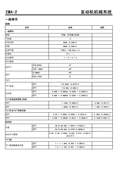
EMA-1.8发动机机械系统
3.5 ~ 5.0 7.0 ~ 9.0 7.0 ~ 9.0 4.0 ~ 5.0
6.5 ~ 8.5 5.0 ~ 6.5 5.0 ~ 6.5 9.0 - 11.0 5.0 ~ 6.5 5.0 ~ 6.5 5.0 ~ 6.5 5.0 ~ 6.5 5.0 ~ 6.5
5.0 ~ 5.3
25.3 ~ 36.2 50.6 ~ 65.1 50.6 ~ 65.1 28.9 ~ 36.2
0.05mm (0.0020in)以下 0.1mm (0.004in) 以下 0.100 ~ 0.250mm (0.0039 ~ 0.010in)
0.4mm(0.0157in)
0.024 ~ 0.044mm (0.0009 ~ 0.0017in) 0.25mm (0.01in)
44.720~44.920mm (1.7606~1.7685in) 44.620~44.820mm (1.7567~1.7646in) 27.964~27.980mm (1.1009~1.1016in) 0.027 ~ 0.061mm (0.0011 ~ 0.0024in) 0.1 ~ 0.2mm (0.0040 ~ 0.0079in)
连杆盖螺母
34.3 ~ 49.0 68.6 ~ 88.3 68.6 ~ 88.3 39.2 ~ 49.0
63.7 ~ 83.4 49.0 ~ 63.7 49.0 ~ 63.7 88.3 ~ 107.9 49.0 ~ 63.7 49.0 ~ 63.7 49.0 ~ 63.7 49.0 ~ 63.7 49.0 ~ 63.7
干燥类型 织布型式
膨胀谐振型式 橡胶悬架
冷却水防冻剂的最大比率 50℃
前发动机支架螺栓和螺母 前止动器支架螺栓 后止动块 bracket 螺栓 后发动机止动支架螺栓
SP系列单元缸分解作业指导书

作业指导书SP系列单元缸分解目次1.工前准备 (1)2.外观检查 (2)3.分解 (3)4.配件清理 (11)5.完工清理 (12)制动装置检修作业指导书类别:A2、A3级检修系统:制动装置部件:SP系列单元制动缸SP系列单元缸分解作业指导书适用车型:25B、25G 、25K、19K、25T作业人员:制动钳工1名作业时间:10-15分钟/个工装工具:单元缸分解工作台、传送带、台虎钳17X14㎜呆扳手、200㎜活动扳手、风动扳手、M14套筒、 200㎜管钳、轴用挡圈卡钳、孔用挡圈卡钳、平口螺丝刀、手锤作业材料:棉纱作业场所:制动室单元制动缸分解间环境要求:室内照明和通风良好,地面清洁,无油泥、杂物,分解台表面目视不得有明显灰尘。
操作规程:参考文件:1.《铁路客车空气制动装置检修规则》铁总运(2014)215号安全防护及注意事项:1.警告——作业者必须穿戴防护手套、作业帽、作业服;2.警告——分解过程中应防止配件砸伤手脚。
基本技术要求:1.分解前须清除表面锈垢,污垢,分解过程中须采取保护措施防止磕碰损伤。
2.单元制动缸各零部件须按顺序分解彻底,橡胶件和缸盖紧固螺栓全数报废。
序号作业项目工装及材料作业程序和标准作业图示1 工前准备工装:单元缸分解工作台、台虎钳、17X14㎜呆扳手、风动扳手、M14套筒、200㎜管钳、轴用挡圈卡钳、孔用挡圈卡钳、平口螺丝刀、手锤、托盘1.1 穿戴好劳保服、鞋、帽、手套。
检查工具齐全、状态良好。
【图1】警告—— 1.职工劳动保护着装规范,穿劳保皮鞋,防止滑倒受伤。
图1 工具序号作业项目工装及材料作业程序和标准作业图示2 外观检查钢丝刷2.1 检查单元缸体外部除锈质量状态,要求除锈质量达到Sa2级,除锈质量不合格的用白粉笔画上重新除锈标记后放入另一个平台返回下部配件组重新抛丸除锈。
序号作业项目工装及材料作业程序和标准作业图示3 分解台虎钳3.1 分解丝杆组成3.1.1 取下防尘套,将丝杠组成按逆时针方向旋下。
EM-1.6发动机机械系统

类型串联、DOHC气缸数4气缸内径76.5mm(3.0118in)冲程87mm(3.4252in)总排气量1,599cc(97.57cu.in)压缩比10.0:1点火顺序1-3-4-2进气门断路ATDC8°~BTDC32°闭合ABDC60°~ABDC20°排气环断路BBDC46°闭合ATDC10°衬垫面平面度小于0.03mm(0.0012in)歧管的平整性进气小于0.15mm(0.0059in)装配表面排气小于0.15mm(0.0059in)阀门导管孔直径(进气,排气)STD11.000~11.018mm(0.4331~0.4338in) 0.05OS11.050~11.068mm(0.4350~0.4357in) 0.25OS11.250~11.268mm(0.4429~0.4436in) 0.50OS11.500~11.518mm(0.4528~0.4535in)进气门座圈孔直径STD30.400~30.421mm(1.1968~1.1977in)0.3OS30.700~30.721mm(1.2087~1.2095in)0.6OS31.000~31.021mm(1.2205~1.2213in)排气门座环孔直径STD27.000~27.021mm(1.0630~1.0638in)0.3OS27.300~27.321mm(1.0748~1.0756in)0.6OS27.600~27.621mm(1.0866~1.0874in)凸轮高度进气43.7492~43.9492mm(1.72241~1.73028in)排气44.1494~44.3494mm(1.73816~1.74604in)轴颈外径(进气,排气)26.964~26.980mm(1.0616~1.0622in)凸轮轴盖油隙0.027~0.061mm(0.0011~0.0024in)0.1mm(0.0039in)轴向间隙0.10~0.20mm(0.0039~0.0079in)气门长度进气91.8mm(3.6142in)排气92.4mm(3.6378in)杆外径进气 5.965~5.980mm(0.2348~0.2354in)排气 5.950~5.965mm(0.2343~0.2348in)气门头部面角45˚~45˚30'气门头部厚度(边缘)进气 1.1mm(0.0433in)0.8mm(0.0315in)排气 1.3mm(0.0512in.) 1.0mm(0.0394in)气门杆至气门导管间隙进气0.02~0.05mm(0.0008~0.0020in)0.10mm(0.0039in)排气0.035~0.065mm(0.0014~0.0026in)0.15mm(0.0059in)长度进气36.3~36.7mm(1.4291~1.4449in)排气39.3~39.7mm(1.5472~1.5630in)气门座接触面的宽度进气0.8~1.2mm(0.0315~0.0472in)排气 1.3~1.7mm(0.0512~0.0669in)气门座角度进气45˚~45˚30'排气45˚~45˚30'自由长度44.0mm(1.7323in)负荷21.6±1.1kg/35mm(47.6±2.4lb/1.3780in)45.1±2.2kg/27.2mm(99.4±4.9lb/1.0709in)直角度最大值1.5°3°气缸内径76.50~76.53mm(3.0118~3.0130in)衬垫面平面度小于0.05mm(0.0020in)活塞外径76.47~76.50mm(3.0106~3.0118in)活塞--气缸间隙0.020~0.040mm(0.0008~0.0016in)环槽宽度1号环槽 1.230~1.255mm(0.0484~0.0494in)2号环槽 1.230~1.255mm(0.0484~0.0494in)油环槽 2.030~2.055mm(0.0799~0.0809in)侧间隙No.1环0.04~0.085mm(0.0016~0.0033in)0.1mm(0.0039in) No.2环0.04~0.085mm(0.0016~0.0033in)0.1mm(0.0039in)油环0.08~0.175mm(0.0031~0.0069in)端隙No.1环0.15~0.30mm(0.0059~0.0118in) 1.0mm(0.0394in) No.2环0.35~0.50mm(0.0138~0.0197in) 1.0mm(0.0394in)油环0.20~0.70mm(0.0079~0.0276in) 1.0mm(0.0394in)活塞销外径18.001~18.007mm(0.7087~0.7089in)活塞销孔内径18.016~18.021mm(0.7093~0.7095in)活塞销孔间隙0.011~0.018mm(0.0004~0.0007in)连杆小头孔内径17.974~17.985mm(0.7076~0.7081in)连杆小头孔间隙-0.032~-0.016mm(-0.0013~-0.0006in)活塞销压入负荷500~1,500kg(1,102~3,306lb)连杆大头-末端内径48.000~48.018mm(1.8898~1.8905in)连杆轴承油膜间隙0.018~0.036mm(0.0007~0.0014in)侧间隙0.10~0.25mm(0.0039~0.0098in)0.4mm(0.0157in)主轴颈外径49.950~49.968mm(1.9665~1.9672in)销外径44.954~44.972mm(1.7698~1.7705in)主轴承油膜间隙No.1,2,4,50.022~0.040mm(0.0009~0.0016in)0.1mm(0.0039in) No.30.028~0.046mm(0.0011~0.0018in)0.1mm(0.0039in)轴向间隙0.05~0.175mm(0.0020~0.0069in)0.2mm(0.0079in)跳动量0.1mm(0.0039in)0.13mm(0.0051in)侧间隙内转子0.040~0.085mm(0.0016~0.0033in)外转子0.040~0.090mm(0.0016~0.0035in)壳体间隙0.060~0.090mm(0.0024~0.0035in)安全阀开启压力500±49.0kpa(5.1±0.5kg/cm²,72.5±7.1psi)卸压弹簧自由长度46.6mm(1.8346in)负荷 6.1±0.4kg/40.1mm(13.4±0.9lb/1.5787in)油量(总计) 3.8L(4.01US qt,3.34lmp qt)油量(油底壳) 3.0L(3.17US qt,2.63lmp qt)油量(排出并重新添加(包括油滤清器)) 3.3L(3.48US qt,2.90lmp qt)油量API SJ/SL以上或SAE5W-20机油压力(怠速)107.8kpa(1.1kg/cm²,15.6psi)冷却方式用冷却风扇强制循环冷却液 5.5~5.8L(5.81~6.13US qt, 4.84~5.10lmp qt)节温器类型蜡球式开启温度82±1.5˚C(179.6±2.7˚F)全开启温度95˚C(203˚F)散热器盖主阀开启压力93.16~122.58kpa(0.95~1.25kg/cm²,13.51~17.78psi)真空阀开启压力0.98~4.90kpa(0.01~0.05kg/cm²,0.14~0.71psi)类型热敏电阻式电阻20°C(68°F) 2.45±0.14kΩ80˚C(176˚F)0.3222kΩ发动机支撑架螺栓244.1~53.9 4.5~5.532.5~39.8发动机支架螺母144.1~53.9 4.5~5.532.5~39.8发动机托架支撑螺拴244.1~53.9 4.5~5.532.5~39.8后平板螺栓19.8~11.8 1.0-1.27.2~8.7发动机固定支架和车身固定螺拴349.0~63.7 5.0~6.536.2~47.0发动机装配绝缘垫和发动机装配支架固定螺母163.7~83.4 6.5~8.547.0~61.5发动机固定支架和发动机支架固定螺栓149.0~63.7 5.0~6.536.2~47.0发动机固定支架和发动机支架固定螺母249.0~63.7 5.0~6.536.2~47.0变速器装配支架和车体固定螺栓。
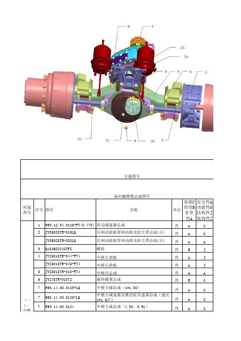
方盛STR系列配件爆炸图明细2017.12.23
18 780.32.0088
19 AZ91.14.32.0002
20 Q1201028F3
(二 )、 主减 速器 组件
21 Q340B10 22 Q40310
轮间差速器壳总成 半轴齿轮 半轴齿轮垫片 半轴齿轮垫片 半轴齿轮垫片 半轴齿轮垫片 半轴齿轮垫片 六角头螺栓 行星齿轮垫片 衬套-行星齿轮 垫圈 行星齿轮 差速器十字轴
件B
G
件B
G
件B
G
件B
10 990.14.32.0120
11 Q5210820
12 无
13 Q18116115TF2
15 990.14.32.0257
15 990.14.32.0256
16 990.14.32.0208
990.14.32.0137
990.14.32.0137-B
30311
17 990.14.32.0140
后制动底板带制动蹄及防尘罩总成(右)
件
A
A
3 Q151B22240TF2
螺栓
件B
J
4 JY2501STR-044-FT4
中桥左滑板
件A
J
JY2501STR-045-FT4
中桥右滑板
件A
J
5 JY2501STR-010-FT4
中桥壳总成
件A
A
6 JY24STR-01072
磁性螺塞总成
件B
G
7 990.14.00.0123-LQ
G
件B
G
件B
G
件B
G
套B
G
套B
G
件B
G
件B
G
件C
G
件B
MB-Z

12V 200V以下 A64
24V
―
―
―
100V,200V
―
― ―
A33 A34 A44
● ―●● ● ―●― ― ――― ― ――― ― ―――
诊断指示(2色显示) 直接出线式
―
― A59W
―
● ―●―
※※上述型号的产品上可安装防水性强的磁性开关,但并不能保证其防水性能。 耐水环境下使用的场合推荐使用防水性强的产品。
32
40
50
63
80
100
单杆双作用
空气
ڇ ߇
ມ
1.5MPa
ፕ
ᆩ
1.0MPa
0.05MPa
环境温度及使用流体温度 给油
无磁性开关 :-10~70℃ (未冻结) 带磁性开关 :-10~60℃
Ք ጚ
႙
不要(不给油)
使用活塞速度 行程长度允差 缓冲 连接口径(Rc)
50~1000mm/s
~250 :+ 10.0, 251~1000 :+ 10.4, 1001~1500 :+ 10.8
ሜዊଉDŽkgDž
理论输出力表
(单位 :N)
OUT
IN
缸径 杆径 动作 受压面积 (mm) (mm) 方向 (mm2) 0.2 0.3 0.4
OUT 804 161 241 322
32
12
IN
691 138 207 276
OUT 1257 251 377 503
40
16
IN 1056 211 317 422
关于磁性开关的规格参见P.17~22。
·适合磁性开关安装位置(行程末端检测时)以及安装高度 ·动作范围 ·可以安装磁性开关的最小行程 ·磁性开关的安装件/零部件型号
海斯特器缸式货车 Hyster H25-32XD 系列技术指南说明书
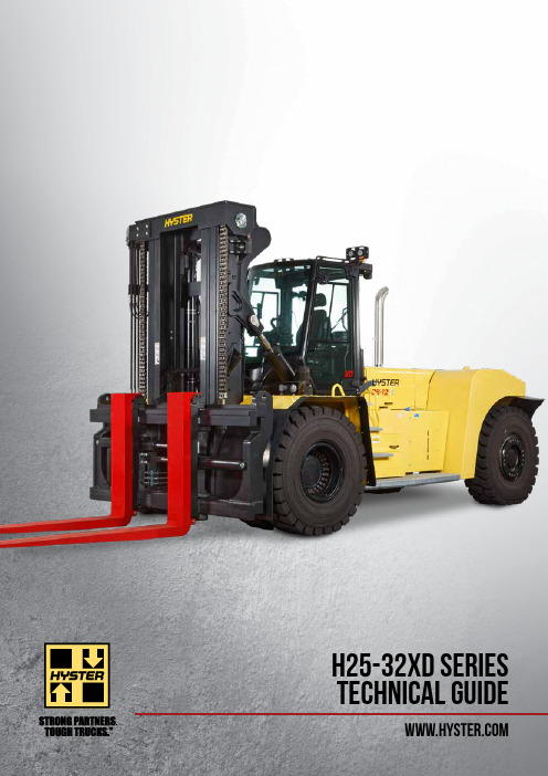
H25-32XD SERIESTECHNICAL GUIDE= Centre of gravity of unladen truckA ST = W a + x + l 6 + a (if b 12/2 < b 13)A ST = W a + ((l 6+x)^2 + (b 12/2-b 13)^0.5 + a (if b 12/2 > b 13 and W a > b 13+ b 12/2)A ST = b 13 + b 12/2 ((l 6+x)^2 + (b 12/2-b 13)^0.5 + a (if b 12/2 > b 13 and W a < b 13+ b 12/2)a = Minimum operating clearance = 10% of A ST(VDI standard = 200 mm BITA recommendation = 300 mm)l 6 = load lengths b 12= load width7-1Engine manufacturer / model Mercedes / OM936Mercedes / OM936G E N E R A L1-1Manufacturer HYSTER HYSTER1-2Model designation H25XDS9; H25XD12H28XD12; H30-32XD(S)121-3Powertrain / drivetrainDieselDiesel10-1Operating pressure for attachments bar 225D R I V E 8-1Drive control / Transmission Type / #Torque Converter Torque Converter 8-2Transmission manufacturer / type Type / #ZF - 5WG211ZF - 5WG2118-4Transmission speeds forward / backward # 5 / 3 5 / 3 8-5CouplingType Torque Converter Torque Converter 8-6Wheel drive / drive axle manufacturer / type Type / #Axle Tech PRLC1794W4H Axle Tech PRC3806W4H 8-11Service brake Type Oil immersed disc Oil immersed disc 8-12Parking brakeType Dry disc on drive axleDry disc on drive axlecs m 1m 2α~β~lxy l 2l 1h 10h 6h 1h3h 4h 7Qb 13b 10eb 3b 2lxa/2W aa/2A stb 11DIMENSIONSH30XD9 / H30XD12 / H32XD9 / H32XD12 SPECIFICATIONSH25XDS9 / H25XD12 / H28XD12 SPECIFICATIONS1-11-2(1) Unladen with new tyres(2) Bottom of forks(3) Full suspension seat in depressed position (4) Length without carriage (5) Forks in alternative position(6) Distance centre truck to centre of internal turning radius(7) Gradeability figures are provided for comparison of tractive performance, but are not intended to endorse the operation of vehicle on the stated inclines. Follow instructions in the operating manual regarding operation on inclines.G E N E R A L1-1Manufacturer HYSTER HYSTER HYSTER HYSTER 1-2Model designation H30XD9H30XD12H32D9H32XD121-3Powertrain / drivetrain Diesel Diesel Diesel Diesel 1-4Operator typeSeatedSeated Seated Seated 1-5Load capacity at load center, nominal Q kg 29,70030,00031,95032,0001-6Load center distance c mm 9001,2009001,2001-8Load distance x mm 1,2741,2741,2741,2741-9Wheelbase ymm 3,9354,3153,9354,825W T .2-1Service weightkg 45,32546,26245,93545,8682-2Axle loading with load, front / rear kg 69,5495,47770,7405,52273,0964,78971,8985,9702-3Axle loading without load, front / rear kg23,44021,88523,54022,72323,49522,44123,49022,378W H E E L S3-1Tyre type Pneumatic Pneumatic Pneumatic Pneumatic 3-2Tyre size, front 16.00 - 25 32PR 16.00 - 25 32PR 16.00 - 25 32PR 16.00 - 25 32PR 3-3Tyre size, rear16.00 - 25 32PR 16.00 - 25 32PR 16.00 - 25 32PR 16.00 - 25 32PR 3-5Wheels, number front / rear (x = driven wheels)x 4 / 2x 4 / 2x 4 / 2x 4 / 23-6Tread, front b 10mm 2,4242,4242,4242,4243-7Tread, rearb 11mm 2,3382,3382,3382,338D I M E N S I O N S4-1Mast tilt, forward / backward α/βdeg6° / 10°6° / 10°6° / 10°6° / 10°4-2Height, mast lowered (1)h 1mm 4,2244,2244,2244,2244-3Free lift h 2mm 00004-4Lift (2)h 3mm 4,2654,2654,2654,2654-5Height, mast extended h 4mm 6,3566,3566,3566,3564-7Cab height (open cab)h 6mm 3,4953,4953,4953,4954-7-1Height of overhead guard (closed cab)h 6mm 3,5223,5223,5223,5224-7-2Height of overhead guard (closed cab w/ airco)h 6mm 3,5223,5223,5223,5224-7-3Height of overhead guard (closed cab w/ strobe light)h 6mm 3,6193,6193,6193,6194-7-4Height of overhead guard (closed cab w/ work lights)h 6mm 3,6713,6713,6713,6714-7-5Height of overhead guard (closed cab w/ airco & strobe light)h 6mm 3,6493,6493,6493,6494-8Seat height relating to SIP (3)h 7mm 2,2922,2922,2922,2924-12Coupling height h 10mm 1,0311,0311,0311,0314-19Overall lengthl 1mm 8,6869,0668,6869,5764-20Length to face of forks (4)l 2mm 6,2466,6266,2467,1364-21Overall widthb 2mm 3,4303,4303,4303,4304-22Fork dimensions ISO 2331s/e/lmm105 / 300 / 2,440105 / 300 / 2,440105 / 300 / 2,440105 / 300 / 2,4404-23Fork carriage type Dual Function - Sideshift Fork Positioning Hook type Dual Function - Sideshift Fork Positioning Hook type Dual Function - Sideshift Fork Positioning Hook type Dual Function - SideshiftFork Positioning Hook type 4-24Fork carriage widthb 3mm 3,2003,2003,2003,2004-25Distance over fork arms, minimum / maximum b 5mm 1,4803,1401,4803,1401,4803,1401,4803,1404-25-1Distance over fork arms, minimum / maximum (5)b 5mm 9302,5909302,5909302,5909302,5904-30Sideshift @ width over forks b 8mm +/-4152,310+/-4152,310+/-4152,310+/-4152,3104-31Ground clearance, laden, below mast m 1mm 2272272272274-32Ground clearance, centre of wheelbase m 2mm 5025025025024-33Load dimension b 12 × l 6 crossways mm 2,4002,4002,4002,4002,4002,4002,4002,4004-34-1-2Aisle width, without operating clearance Ast mm 9,3659,8599,36510,5224-34-1-2Aisle width, with 200 mm operating clearance Ast mm 9,56510,0599,56510,7224-34-1-3Aisle width, with 10% operating clearance Ast mm 10,30210,84510,30211,5744-35Outside turning radius W a mm 5,6916,1855,6916,8484-36Internal turning radius (6)b 13mm 2,2732,5892,2733,013P E R F O R M A N C E5-1Travel speed, with / without loadkm/h 25252525252525255-2Lifting speed, with / without load backwards m/s 0.270.290.270.290.270.290.270.295-2-1Lifting speed, with 70% load m/s 0.280.280.280.285-3Lowering speed with / without loadm/s 0.500.500.500.500.500.500.500.505-5Drawbar pull - 1.6 km/h | 1 mph, with / without load kN 1982031982031972031972035-5-1Drawbar pull - stall, with / without loadkN 2402452402452402452402455-7Gradeability - 1.6 km/h | 1 mph, with / without load (7)%28352735273427365-7-1Gradeability - stall, with / without load (7)%35353435333433365-9Acceleration time, with / without loadsecOn request On request On request On request(1) Unladen with new tyres (2) Bottom of forks(3) Full suspension seat in depressed position (4) Length without carriage (5) Forks in alternative position(6) Distance centre truck to centre of internal turning radius(7) Gradeability figures are provided for comparison of tractive performance, but are not intended to endorse the operation of vehicle on the stated inclines. Follow instructions in the operating manual regarding operation on inclines.MAST AND CAPACITY INFORMATIONMAST AND CAPACITY INFORMATIONH25XDS9 RATED CAPACITY KG @ 900 MM AND @1200 LOAD CENTRELift height h 3 (mm)Lowered height h 1 (mm)Free lift height h 2 (m)Extended height h 4 (mm)Dual Function Side Shift & Fork Positiong carriagewithout ZERO IN-TO-IN forkpositioning Dual Function Side Shift & Fork Positiong carriagewith ZERO IN-TO-IN forkpositioning Capacity @ 900 mm load centre (kg)Mast tilt (forward/backward) (°)Capacity @ 1.200 mm load centre (kg)Capacity @ 900 mm load centre (kg)Mast tilt (forward/backward) (°)Capacity @ 1.200 mm load centre (kg)2 S T A G E N F L3,1553,49105,01625,000 6 / 1022,70025,000 6 / 1022,7003,7603,79405,62125,000 6 / 1022,64025,000 6 / 1022,6404,3704,09906,23125,000 6 / 1022,60025,000 6 / 1022,6004,9804,40406,84125,000 6 / 1022,54025,000 6 / 1022,5406,2005,01408,06125,000 6 / 1022,40025,000 6 / 1022,4009,2506,53911,11123,7206 / 621,00020.520 #)6 / 621.000 #)H25XD12 RATED CAPACITY KG @1200 LOAD CENTRELift height h 3 (mm)Lowered height h 1 (mm)Free lift height h 2 (m)Extended height h 4 (mm)Dual Function Side Shift & Fork Positiong carriagewithout ZERO IN-TO-IN forkpositioning Dual Function Side Shift & Fork Positiong carriagewith ZERO IN-TO-IN forkpositioning Mast tilt (forward/backward) (°)Capacity @ 1.200 mm load centre (kg)Mast tilt (forward/backward) (°)Capacity @ 1.200 mm load centre (kg)2 S T A G E N F L3,1553,49105,016 6 / 1022,700 6 / 1022,7003,7603,79405,621 6 / 1022,640 6 / 1022,6404,3704,09906,231 6 / 1022,600 6 / 1022,6004,9804,40406,841 6 / 1022,540 6 / 1022,5406,2005,01408,061 6 / 1022,400 6 / 1022,4009,2506,53911,1116 / 621,0006 / 621.000 #)H28XD12 RATED CAPACITY KG @ 900 MM AND @1200 LOAD CENTRELift height h 3 (mm)Lowered height h 1 (mm)Free lift height h 2 (m)Extended height h 4 (mm)Dual Function Side Shift & Fork Positiong carriagewithout ZERO IN-TO-IN forkpositioning Dual Function Side Shift & Fork Positiong carriagewith ZERO IN-TO-IN forkpositioning Capacity @ 900 mm load centre (kg)Mast tilt (forward/backward) (°)Capacity @ 1.200 mm load centre (kg)Capacity @ 900 mm load centre (kg)Mast tilt (forward/backward) (°)Capacity @ 1.200 mm load centre (kg)2 S T A G E N F L2,8503,46404,83631,860 6 / 1028,00031,860 6 / 1028,0003,1553,61605,14131,860 6 / 1028,00031,860 6 / 1028,0003,7603,91905,74631,860 6 / 1028,00031,860 6 / 1028,0004,3704,22406,35631,860 6 / 1028,00031,860 6 / 1028,0006,2005,13908,18631,860 6 / 1028,00031,860 6 / 1028,0006,8105,44408,71631,700 6 / 1027,86031,700 6 / 1027,8609,2507,174011,74630,920 6 / 627,18030.920 #) 6 / 627.180 #)9,8607,47912,35630,6006 / 626,90029.660 #)6 / 626.900 #)H30XD9 RATED CAPACITY KG @ 900 MM AND @1200 LOAD CENTRELift height h 3 (mm)Lowered height h 1 (mm)Free lift height h 2 (m)Extended height h 4 (mm)Dual Function Side Shift & Fork Positiong carriagewithout ZERO IN-TO-IN forkpositioning Dual Function Side Shift & Fork Positiong carriagewith ZERO IN-TO-IN forkpositioning Capacity @ 900 mm load centre (kg)Mast tilt (forward/backward) (°)Capacity @ 1.200 mm load centre (kg)Capacity @ 900 mm load centre (kg)Mast tilt (forward/backward) (°)Capacity @ 1.200 mm load centre (kg)2 S T A G E N F L2,8503,46404,83630,000 6 / 1027,00030,000 6 / 1027,0003,1553,61605,14130,000 6 / 1027,00030,000 6 / 1027,0003,7603,91905,74630,000 6 / 1026,94030,000 6 / 1026,9404,3704,22406,35630,000 6 / 1026,88030,000 6 / 1026,8806,2005,13908,18630,000 6 / 1026,62030,000 6 / 1026,6206,8105,44408,71629,840 6 / 1026,42029.840 #) 6 / 1026.420 #)9,2507,174011,74628,880 6 / 625,360 28.880 #) 6 / 625.360 #)9,8607,479012,35628,580 6 / 625,12028.580 #) 6 / 625.120 #)H30XD12 RATED CAPACITY KG @ 900 MM AND @1200 LOAD CENTRELift height h 3 (mm)Lowered height h 1 (mm)Free lift height h 2 (m)Extended height h 4 (mm)Dual Function Side Shift & Fork Positiong carriagewithout ZERO IN-TO-IN forkpositioning Dual Function Side Shift & Fork Positiong carriagewith ZERO IN-TO-IN forkpositioning Capacity @ 900 mm load centre (kg)Mast tilt (forward/backward) (°)Capacity @ 1.200 mm load centre (kg)Capacity @ 900 mm load centre (kg)Mast tilt (forward/backward) (°)Capacity @ 1.200 mm load centre (kg)2 S T A G E N F L2,8503,46404,83632,000 6 / 1030,00032,000 6 / 1030,0003,1553,61605,14132,000 6 / 1030,00032,000 6 / 1030,0003,7603,91905,74632,000 6 / 1030,00032,000 6 / 1030,0004,3704,22406,35632,000 6 / 1030,00032,000 6 / 1030,0006,2005,13908,18632,000 6 / 1030,00032,000 6 / 1030,0006,8105,44408,71631,840 6 / 1029,84031,840 6 / 1029,8409,2507,174011,74631,100 6 / 629,00031.100 #) 6 / 629.000 #)9,8607,479012,35630,880 6 / 629,68029.840 #) 6 / 628.720 #)H32XD9 RATED CAPACITY KG @ 900 MM AND @1200 LOAD CENTRELift height h 3 (mm)Lowered height h 1 (mm)Free lift height h 2 (m)Extended height h 4 (mm)Dual Function Side Shift & Fork Positiong carriagewithout ZERO IN-TO-IN forkpositioning Dual Function Side Shift & Fork Positiong carriagewith ZERO IN-TO-IN forkpositioning Capacity @ 900 mm load centre (kg)Mast tilt (forward/backward) (°)Capacity @ 1.200 mm load centre (kg)Capacity @ 900 mm load centre (kg)Mast tilt (forward/backward) (°)Capacity @ 1.200 mm load centre (kg)2 S T A G E N F L2,8503,46404,83632,000 6 / 1028,68032,000 6 / 1028,6803,1553,61605,14132,000 6 / 1028,64032,000 6 / 1028,6403,7603,91905,74632,000 6 / 1028,56032,000 6 / 1028,5604,3704,22406,35632,000 6 / 1028,50032,000 6 / 1028,5006,2005,13908,18632,000 6 / 1028,24032,000 6 / 1028,2406,8105,44408,71631,840 6 / 1028,04031,840 6 / 1028,0409,2507,174011,74630,020 6 / 626,36030.020 #) 6 / 626.360 #)9,8607,479012,35629,420 6 / 626,16029.420 #) 6 / 626.120 #)Lift height h 3 (mm)Lowered height h 1 (mm)Free lift height h 2 (m)Extended height h 4 (mm)Dual Function Side Shift & Fork Positiong carriagewithout ZERO IN-TO-IN forkpositioning Dual Function Side Shift & Fork Positiong carriagewith ZERO IN-TO-IN forkpositioning Mast tilt (forward/backward) (°)Capacity @ 1.200 mm load centre (kg)Mast tilt (forward/backward) (°)Capacity @ 1.200 mm load centre (kg)2 S T A G E N F L2,8503,46404,836 6 / 1032,000 6 / 1032,0003,1553,61605,141 6 / 1032,000 6 / 1032,0003,7603,91905,746 6 / 1032,000 6 / 1032,0004,3704,22406,356 6 / 1032,000 6 / 1032,0006,2005,13908,186 6 / 1032,000 6 / 1032,0006,8105,44408,716 6 / 1032,000 6 / 1032,0009,2507,174011,746 6 / 631,020 6 / 631,0209,8607,479012,356 6 / 630,720 6 / 629,820FEATURES AND OPTIONSFEATURES AND OPTIONSPERFORMANCEMercedes OM936 7.7L Stage V diesel engine: Rated/peak * S tandard or optional in selected markets or models. Other options available through Special Products Engineering Department (SPED). Contact Hyster for details.VISIBILITY (continued)STD OPT2 HP LED work lights on front mast with 2 on rear and front fenders / brake / tail / back-up lights with turn signalsX 4 HP LED work lights on cab with 2 on rear and front fenders (LED) / brake / tail / back-up lights with turn signalsX 4 LED work lights cab mounted, 2 LED drive lights with position and direction front fender mounted, 2 LED work lights on rear of operator compartment / LED rear ward cluster with stop, tail, indicator & reverse lightsX2 LED Work lights mast mounted, 2 LED drive lights withposition and direction front fender mounted, 2 LED work lights on rear of operator compartment / LED rearward cluster with stop, tail, indicator & reverse lights X LED headlights, 2 front (mast mounted)XOPERATIONSTD OPTAir hornX Electrical hornX Audible reverse alarmXAudible white noise reverse alarm X Audible alarm - forward / reverse X Amber strobe light - ignition activatedX Blue LED spotlight - rear - reverse direction activation X Forward camera mounted on outer mast X Forward camera mounted on carriage X Park brake - manualX Truck start – key switch with start button – without seatbelt interlockXTruck start – key switch with start button and seatbelt interlockX Operator password in display - required for truck start X Directional lever X MONOTROL TMX Directional control on mini-levers XDirectional control on joystickX Automatic truck shutdown with timerX Delayed engine shutdown for turbo cooldown X Air-conditioning shut-off with open door X Tyre pressure monitoring system X Load weight indicatorX Engine oil level on display and dipstick X Engine oil level on displayX Coolant level warning on displayXCoolant level warning on display and sight glassX Power distribution panel with fuses partially replaced by electric circuit breakers X Rear axle load indicatorX Hydraulic load weighing system X Rear radar object detection system X Automatic fire suppression system X 2 front / 2 rear lifting eyes X Greasing base truckX Greasing hose towards top end mast X Centralized greasing system top endmast X Mud guards front and rear X Lockable fuel cap X Non-kockable fuel capXStainless steel strainer in fuel neck X Hyster Tracker wireless monitoring XHyster Tracker wireless access X Hyster Tracker wireless verificationX DC/DC 24/12V converter with 1 power sockets and 2 USB outletsX DC/DC 24/12V converter with 2 power sockets and 2 USB outletsX Jump start connector to battery with NATO connector X Engine block heater 230VX Hydraulic temperature protectionXAPPEARANCESTD OPTHyster yellow paint base truck XReplace yellow with 1 colourX Replace yellow with 2 colours (mast, cabin and wheels not included)X Outside of cab painted special color X Complete cab painted special colourX Wheel rim side view painted same colour as base truck X Counterweight hazard warning stripesXSUPPLEMENTALSTD OPTLiterature pack X CE certificationX 24 months / 4000 hours extended warrantyX12 months / 2,000 hours manufacturers warrantyXFRONT END EQUIPMENTRANGE OF 2 STAGE NFL MASTSPin Type and Quick Disconnect Hook Type forks3.100 mm wide Side shift frame carriage – Pin type forks3.100 mm wide Side shift frame carriage with Fork Positioning – Individual Fork Control – Pin type forksMono Mast Integrated Coil ram carriage3.040 mm wide hook type mount Dual Function carriage with Side shift and Fork Positioning – Individual Fork Control – Hook type forks 3.200 mm wide Multi Purpose Dual Function carriage with Side shift andFork Positioning – Individual Fork Control – Hook type forksSide shift frame pin type mount Integrated Coil Ram carriage Coil ramFRONT END EQUIPMENT3.100 mm wide Standard Carriage – Pin type forks3.100 mm wide Carriage with Fork Positioning – Individual Fork Control – Pin type forkswww.hyster.eu*********************/HysterEurope@HysterEurope/HysterEuropeSTRONG PARTNERS. TOUGH TRUCKS.TMFOR DEMANDING OPERATIONS, EVERYWHERE.Hyster supplies a complete range of warehouse equipment, IC and electric counterbalanced trucks, container handlers and reach stackers. Hyster is committed to being much more than a lift truck supplier.Our aim is to offer a complete partnership capable ofresponding to the full spectrum of material handling issues: Whether you need professional consultancy on your fleet management, fully qualified service support, or reliable parts supply, you can depend on Hyster.Our network of highly trained dealers provides expert,responsive local support. They can offer cost-effective finance packages and introduce effectively managed maintenance programmes to ensure that you get the best possible value. Our business is dealing with your material handling needs so you can focus on the success of your business today and in the future.HYSTER-YALE UK LIMITED trading as Hyster Europe. Registered Address: Centennial House, Building 4.5, Frimley Business Park, Frimley, Surrey GU16 7SG, United Kingdom.Registered in England and Wales. Company Registration Number: 02636775. ©2020HYSTER-YALE UK LIMITED, all rights reserved. HYSTER,and STRONG PARTNERS. TOUGH TRUCKS. are trademarks of HYSTER-YALE Group, Inc.Hyster products are subject to change without notice. Forklift trucks illustrated may feature optional equipment.Printed in EU. Part number: 3990445 Rev. 01-11/20HYSTER EUROPECentennial House, Frimley Business Park, Frimley, Surrey, GU16 7SG, England.Tel: +44 (0) 1276 538500。
气缸的类型及简图参考资料

数字气缸
将若干个活塞沿轴向依次装在一起,每个活塞的行程由小到大,按几何级数增加
回转气缸
进排气导管和导气头固定而气缸本体可相对转动。用于机床夹具和线材卷曲装置上
伺服气缸
将输入的气压信号成比例地转换为活塞杆的机械位移。用于自动调节系统中。
挠性气缸
缸筒由挠性材料制成,由夹住缸筒的滚子代替活塞。用于输出力小,占地空间小,行程较长的场合,缸筒可适当弯曲
气缸活塞两端有效面积差较大,利用压力差原理使活塞往复运动,工作时活塞杆侧始终通以压缩空气
双活塞气缸
两个活塞同时向相反方向运动
多位气缸
活塞杆沿行程长度方向可在多个位置停留,图示结构有四个位置
串联气缸
在一根活塞杆上串联多个活塞,可获得和各活塞有效面积总和成正比的输出力
冲击气缸
利用突然大量供气和快速排气相结合的方法得到活塞杆的快速冲击运动,用于切断、冲孔、打入工件等
工程工业控制课程设计概述
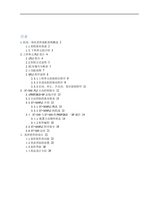
目录1 机电一体化柔性装配系统概述-2 -1.1系统基本组成- 2 -1.2 下料单元的介绍- 3 -2.上料单元PLC设计- 4 -2.1PLC简介- 4 -2.2控制方式说明- 5 -2.3I/O编号分配表- 5 -2.4功能表图- 7 -2.5PLC程序说明- 8 -2.5.1上料单元初始原位程序- 9 -2.5.2步进电机的驱动程序- 9 -2.5.3启动、停止、手自动,复位按钮程序- 11 -3 .S7-300 PLC主站控制部分- 12 -3.1PROFIBUS-DP总线介绍- 13 -3.2主站控制的基本要求- 13 -3.3 S7-300PLC介绍- 13 -3.3.1 S7-300PLC概述- 13 -3.3.2 S7-300PLC的组成- 13 -3.4 S7-200与S7-300的PROFIBUS –DP通信- 14 -3.4.1 配置主站硬件组态- 14 -3.4.2软件编程- 18 -3.5 S7-300PLC程序部分- 19 -3.6 S7-300总结- 21 -4.监控软件的设计- 22 -4.1监控软件的功能- 22 -4.2登录界面的设置- 23 -4.3监控界面- 26 -4.4组态设计小结- 29 -1 机电一体化柔性装配系统概述Me093399型机电一体化教学系统是以工业生产中的自动化装配生产线为原型开发的教学、实验、实训综合应用平台。
本装置采用铝合金结构件搭建各分站主体设备,选取多种机械传动方式实现站间串联,整条生产线充分展现了实际工业生产中的典型部分。
系统控制过程中除涵盖多种基本控制方法外,还凸现组态控制、工业总线、电脑视觉、实时监控等先进技术,为培养现代化应用型人才创设了完整、灵活、模块化、易扩展的理想工业场景。
图1-1连续生产线示意图为便于协调整个生产线的全程控制,系统设置了一个主站总控制台,主站总控制台是整个装配生产线连续运行的指挥调度中心,其主要功能是实现全程运行的总体控制,完成全系统的通讯连接等。
磁性开关SMC

缸径
D-H7型
D-H7C型
D-H7BA型
D-H7NF型
D-H7□W型
D-G5/K5型
D-G5BA型
D-G59F型
D-G5NT型
D-G5□W/K59W型
D-G39/K39型
D-G39A/K39A型
D-F7/J7型
D-J79C型
D-F79F型
D-F7BA型
D-F7BAV型
D-F7□V型
D-F7NT型
无 D-F7□W(V)型
耐热型·2色显示…………………………………………………………………P.1618 宽范围检出型 ……………………………………………………………………P.1619
南
微调电容器磁性开关 ……………………………………………………………P.1620
订制规格 …………………………………………………………………………P.1626
◆有触点磁性开关………………………………………………P.1629
一般(通用)型………………………………………………………………………P.1630 2色显示式…………………………………………………………………………P.1643 耐强磁场·2色显示式……………………………………………………………P.1646 耐热型 ……………………………………………………………………………P.1649
磁 D-A7□H/A80H型
性 D-A73C/A80C型
开 D-A79W型
关 D-A5/A6型
D-A59W型
D-A9型
D-A9□V型
D-E7□A/E80A型
D-Z7/Z8型
D-P7型
D-B3型
执行元件页码索引 (圆型数字为Best No.。)
气缸操作规程

气缸操作规程
《气缸操作规程》
气缸是工业生产中常用的一种执行元件,它具有快速响应、稳定性好等特点,广泛应用于各种机械设备中。
为了确保气缸的安全运行,需要制定一套严格的操作规程,以规范气缸的使用和维护。
首先,在操作气缸之前,操作人员需要进行必要的安全培训,了解气缸的基本结构和工作原理,掌握其操作方法和注意事项。
操作人员必须穿戴好相关的防护装备,遵守相关的安全操作规程。
在使用气缸时,操作人员需要按照气缸的设计参数和工作要求,选择合适的气源(气压),并确保气源的压力稳定。
在连接气源管道时,要确保连接件的牢固,防止气源泄漏。
操作人员在进行气缸操作时,需谨慎操作,避免对气缸产生冲击、碰撞等不利影响。
在维护气缸时,操作人员需要定期对气缸进行检查和维护,包括清洁气缸表面、检查密封件的磨损情况、注油等。
同时在对气缸进行维护时,需要确保停机操作、断开气源,防止发生意外事故。
总的来说,《气缸操作规程》是对气缸使用和维护的一系列规范和要求,其目的是最大程度地确保气缸的安全运行和延长气
缸的使用寿命。
只有严格遵守操作规程,才能有效保障气缸的可靠运行。
Danfoss 自动气缸控制系统产品说明书
1
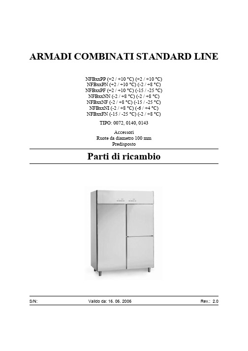
Parti di ricambio
20 30 40
16.6.2006
Rev. 2.0
10
2
Parti di ricambio
16.6.2006
Rev. 2.0
ID Codici del produttore Modello Tipo
Modulo:Unità refrigerata
10 141555100070
5
Parti di ricambio
16.6.2006
Rev. 2.0
80 100 120
140
90 110
130
150
6
Parti di ricambio
16.6.2006
Rev. 2.0
ID Codici del produttore Modello Tipo
Modulo:Termostato e componenti elettrici
N
72
10 141555100050
F
72
10 141552210730
P, N
140, 143
10 141555100055
F
140, 143
20 141632425104
72
20 141622800025
P, N
140, 143
20 141622800018
F
140, 143
1648008200
72
1495230034
140, 143
1648001017
140, 143
1435060035000
72
1435060035001
72
14354008
SMC - 气缸MGP系列

16
8
OUT IN
201 151
40 60 80 101 121 141 161 181 201 30 45 60 75 90 106 121 136 151
20
10
OUT IN
※导线长度记号 0.5m …………… 无记号 1m …………… M 3m …………… L 5m …………… Z
(例) M9NW (例) M9NWM (例) M9NWL (例) M9NWZ
※○符号的无触点磁性开关按订货生产。 ※D-P3DW型在缸径ø25~ø100上可安装。
※除上述记载型号以外,还有其它可能适合的磁性开关,详见P.22。 ※带导线前置插头磁性开关详见Best Pneumatics No.e P.1784、1785。
带端锁/MGP-H/R
LOCK
滑动轴承
• 球轴承
• 高精度球轴承
Best Pneumatics
P.289
Best Pneumatics
P.307
洁净室规格/12/13-MGP
球轴承
Best Pneumatics
P.283
耐水性强型/MGP R/V
Best Pneumatics
P.283
强力导杆型/MGPS
D-P3DW□型的场合,请参考单行样本(S20-201)。 ※磁性开关同包出厂(未组装)。
导线前 置插头
适合负载
IC回路 ―
IC回路 继电器、 ― PLC
IC回路
―
IC回路 ― ― 继电器、
IC回路 PLC
3
关于磁性开关的规格,请参见→P.21~23。
Ą磁性开关合适的安装位置(行程末端检测时)及 安装高度。
(ø12~ø25-25行程时无突出长度)
festo摆动气缸工作原理

festo摆动气缸工作原理
FESTO摆动气缸是一种气动执行元件,它利用压缩空气作为动力源,驱动输出轴在一定角度范围内作往复回转运动。
这种气缸广泛应用于需要角度位移或摆动的自动化控制系统中,如机器人、自动化装配线、阀门控制等。
FESTO摆动气缸的工作原理主要基于气动驱动和机械转换。
以下是摆动气缸的基本工作原理:
1. 气动驱动:当压缩空气输入到气缸的一侧时,气缸内的活塞或叶片受到气压的作用,产生推力。
这个推力通过机械结构转换为旋转力矩,驱动输出轴旋转。
2. 机械转换:摆动气缸内部通常包含齿轮、齿条或其他机械传动机构,这些机构将活塞或叶片的直线运动转换为旋转运动,从而实现输出轴的摆动。
3. 摆动角度调节:许多摆动气缸具有可调节的摆动角度,这通常通过调整气缸内的挡块或限位器来实现。
用户可以根据需要设定输出轴的摆动范围。
4. 双作用设计:FESTO摆动气缸可以是双作用的,这意味着它们可以从两个方向接收压缩空气,从而实现双向摆动。
5. 缓冲和定位:为了提高摆动气缸的稳定性和减少冲击,许多气缸设计有缓冲装置,如弹性垫或液压缓冲器。
此外,气缸还可能配备有定位装置,用于精确控制输出轴的位置。
6. 附件和连接:摆动气缸可以配备各种附件,如连接板、挡块、
液压缓冲器等,以便于安装和集成到自动化系统中。
FESTO摆动气缸的精确度和可靠性使其在自动化和控制技术领域中得到广泛应用。
通过适当的选型和安装,这些气缸可以提供稳定和可重复的运动,满足各种工业应用的需求。
ST轴用组合密封圈
140 155.5
SYTD-22-150
150 165.5
SYTD-22-160
160 175.5
SYTD-22-180
180 195.5
SYTD-22-200
200
221
SYTD-22-220
220
241
10.5
SYTD-22-250
250
271
SYTD-22-280
280 304.5
SYTD-22-300 SYTD-22-320 SYTD-22-360
0.6~0.4
132X5.3 145X5.3 155X5.3 165X5.3 185X5.3 206X7 230X7 258X7 290X7 307X7 325X7 365X7 412X7 462X7
300 324.5
8.1
320 344.5 360 384.5
12.25
1.5 1.0~0.6
SYTD-22-400
400 424.5
SYTD-22-450
450 474.5
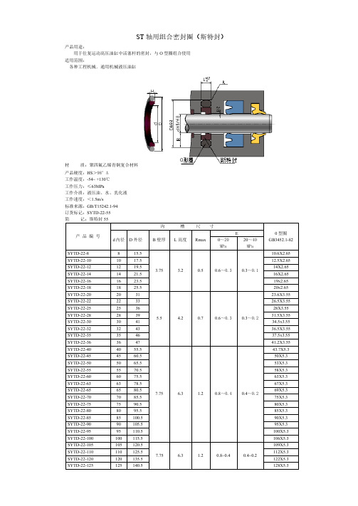
安装说明:1:活塞杆直径大于 30mm,斯特封可直接装入闭式沟槽中,安装方法如图。 2:活塞杆直径小于 30mm,宜采用开口式沟槽。 3:密封件装配之后,可用外径小于公称直径 3%的心轴在槽中进行校准。
ST 轴用组合密封圈(斯特封)
产品用途: 用于往复运动高压油缸中活塞杆的密封,与 O 型圈组合使用
适用范围: 各种工程机械﹑通用机械液压油缸
材 质:聚四氟乙烯青铜复合材料
产品硬度:HS>98°A 工作温度:-54~ +130℃ 工作压力:≤63MPa 工作介质:液压油、水、乳化液 工作速度:<1.5m/s 标准来源:GB/T15242.1-94 订货标记:SYTD-22-55 简 记:斯特封 55
费斯托(Festo)无锈钢气缸产品说明书

Stainless-steel cylindersStainless-steel cylinders Key featuresTheir applicationsReliable components need to be fully functional and operational, even in harsh operating conditions. The aim is to maximise availability of machinery while minimising downtimes. Stain-less-steel cylinders are therefore used in applications where the surface fin-ish of normal pneumatic drives would not be able to withstand the surround-ing media. However, designing a corro-sion-resistant system involves more than simply selecting a suitable steel: it also requires the selection of a matching concept for mounting compo-nents and accessories.Sample application:The atmosphere in the maturing cellar of a cheese factory consists of an un-pleasant mix of ammonia, lactic acid and 98% humidity.Our strengthFesto’s stainless-steel cylinders arecharacterised by resistant materials,such as 1.4301 and 1.4401. Thesepopular high-alloy, stainless austeniticchrome-nickel and chrome-nickel-mo-lybdenum steels protect against chem-ical or electrochemical stress as wellas damage to the surface materialscaused by cleaning agents or disinfect-ants. These groups of materials areparticularly resistant to uniformsurface corrosion and offer increasedprotection against pitting and crevicecorrosion.The benefits to youFesto’s worldwide service network en-sures optimum availability of stain-less-steel cylinders. As well as a com-prehensive range of standards-basedcylinders to DIN ISO 15552 and 6432,we also offer a range of matchingmounting components and accesso-ries. The stainless-steel cylinders areassembled with grease that is compli-ant with NSF-H1 and wipers in accord-ance with BGVV (Federal Institute forRisk Assessment) guidelines. Thismeans that they are suitable for use inthe food area. We will be pleased toprovide you with further informationabout future additions to our stain-less-steel range. Just get in touch withus.Good to knowOur many years of experience in thearea of stainless steel are invaluablewhen you are investigating solutionsfor harsh environments. Our expertswill answer any questions you mighthave about surface finishes andchemical resistance.2d I nternet: /catalogue/...Subject to change – 2023/08Stainless-steel cylinders Key featuresResistanceComplete resistance to pitting and crevice corrosion is not always possi-ble, even with ideal application param-eters. The following parameters in-crease the pitting effect of chloride ions:• Concentration of chloride ions • Duration of contact• Temperature• Decreasing pH valueIt must therefore be ensured during design, assembly and operation that all parts of the machinery can be prop-erly cleaned to avoid an accumulation of chloride ions.Selected sealing materials ensure veryhigh resistance to a wide range ofchemical compounds.Further information on media resist-ance can be obtained on the Internetat .In principle, we recommend that thecylinder be cleaned with the piston rodin the retracted position to avoid therisk of washing out the lifetimelubrication.Various types of machinery contamina-tion make cleaning processes neces-sary in many industry sectors. The de-gree of cleaning required ranges fromwiping the machinery with a dry clothto wet cleaning to foam cleaning withdifferent exposure times andconcentrations.It is therefore impossible to make ageneral recommendation oncompatibility.Wet cleaning Foam cleaning3 2023/08 – Subject to change d I nternet: /catalogue/...Stainless-steel cylindersProduct range overview4d I nternet: /catalogue/...Subject to change – 2023/08Stainless-steel cylinders Product range overview5 2023/08 – Subject to change d I nternet: /catalogue/...Standards-based cylinders CRDSNU to ISO6432, stainless steel Key featuresVariantsCRDSNU Basic version CRDSNU-S2:Through piston rodCRDSNU-MQ:Short end cap without swivelmountingCRDSNU-MG/CRDSNU-B-MG:Bearing cap without mounting threadCushioning typesCushioning P Cushioning PPS Cushioning PPVMode of operation• The drive is equipped with polymerflexible end-position cushioning • The drive is equipped with self-ad-justing end-position cushioning• The drive is equipped withadjustable end-position cushioningApplication• Small loads• Low speeds• Low impact energies • Small to medium loads• Low to medium speeds• Medium impact energies• Medium to high loads• High speeds• High impact energiesAdvantages• No adjustment required• Saves time • No adjustment required• Saves time• Powerful• Very powerful6d I nternet: /catalogue/...Subject to change – 2023/08Standards-based cylinders CRDSNU to ISO6432, stainless steel Peripherals overview7 2023/08 – Subject to change d I nternet: /catalogue/...Standards-based cylinders CRDSNU to ISO6432, stainless steelType codes8d I nternet: /catalogue/...Subject to change – 2023/08Standards-based cylinders CRDSNU to ISO6432, stainless steel Data sheet-N- Diameter12 ... 25 mm-T-Stroke length1 ... 500 mmLonger strokes on request-É-Spare parts service2025G1/8G1/8M8M10x1.251) An increase in the minimum operating pressure is possible with variants2) Additional information /sp aCertificates.1) Note operating range of proximity switches2) Corrosion resistance class CRC 3 to Festo standard FN 940070High corrosion stress. Outdoor exposure under moderate corrosive conditions. External visible parts with primarily functional surface requirements which are in direct contact with a normal industrial environment.9 2023/08 – Subject to change d I nternet: /catalogue/...Standards-based cylinders CRDSNU to ISO6432, stainless steelData sheet1)Note the ATEX certification of the accessories.The values are reduced by approx. 50% at an ambient temperature of 80°C10d I nternet: /catalogue/...Subject to change – 2023/08Standards-based cylinders CRDSNU to ISO6432, stainless steelData sheetMax. transverse force Fq as a function of projection lBasic versionS2 – Through piston rodl [mm]F q [N ]0.111010010000102030405060l [mm]0.111010010000204060801001201030507090110DSNU-12/16DSNU-20DSNU-2512341) Additional information /sp a CertificatesStandards-based cylinders CRDSNU to ISO6432, stainless steel Data sheetStandards-based cylinders CRDSNU to ISO6432, stainless steel Data sheetStandards-based cylinders CRDSNU to ISO6432, stainless steel Data sheetStandards-based cylinders CRDSNU to ISO6432, stainless steel Data sheetStandards-based cylinders CRDSNU to ISO6432, stainless steel Ordering dataStandards-based cylinders CRDSNU to ISO6432, stainless steel Ordering data-NoteH-The bearing cap on stocked parts is made of one piece.When ordered using the modular product system, the bearing cap is made oftwo pieces, which makes it possible to exchange the wiper in the event of arepair.Standards-based cylinders CRDSNU to ISO6432, stainless steel Ordering data[1]-...Longer strokes on request[2]PPS, A1, A2, A3Not with S6, TT[3]A2, S2, TT Not with MG[4]S2Not with MQ[5]K3Not with K2, K5[6]TT Not with S6[7]EX4Not with S6, TT[8]PPS Not with MQ for piston @ 16[9]A2, TT Not with S2, K3[10]P Not with B except for piston @ 16Round cylinders CRDSNU, stainless steel Key featuresVariantsCRDSNU Basic version CRDSNU-S2:Through piston rodCRDSNU-MQ:Short end cap without swivelmountingCRDSNU-MG:Bearing cap without mounting threadCushioning typesCushioning P Cushioning PPS Cushioning PPVMode of operation• The drive is equipped with polymerflexible end-position cushioning • The drive is equipped with self-ad-justing end-position cushioning• The drive is equipped withadjustable end-position cushioningApplication• Small loads• Low speeds• Low impact energies • Small to medium loads• Low to medium speeds• Medium impact energies• Medium to high loads• High speeds• High impact energiesAdvantages• No adjustment required• Saves time • No adjustment required• Saves time• Powerful• Very powerfulRound cylinders CRDSNU, stainless steel Peripherals overview-N-Diameter32 ... 100 mm-T-Stroke length1 ... 500 mmLonger strokes on request-É-Spare parts service63801001) An increase in the minimum operating pressure is possible with variants2) Additional information /sp a Certificates.1) Note operating range of proximity switches2) Corrosion resistance class CRC 3 to Festo standard FN 940070High corrosion stress. Outdoor exposure under moderate corrosive conditions. External visible parts with primarily functional surface requirements which are in direct contact with a normal industrial environment.3) Corrosion resistance class CRC 4 to Festo standard FN 940070Particularly high corrosion stress. Outdoor exposure under extreme corrosive conditions. Parts exposed to aggressive media, e.g. in the chemical or food industries. Such applications may need to be safeguarded by means of special testing (d also FN 940082), using appropriate media.1) Note the ATEX certification of the accessories.1) The values are reduced by approx. 50% at an ambient temperature of 80°CMax. transverse force Fq as a function of projection lBasic versionS2 – Through piston rodl [mm]F q [N ]0.1110100100001002003004005006007008009001000l [mm]0.111010010000400800120016002000DSNU-32DSNU-40DSNU-50/63DSNU-80/100Materials Sectional view 1234-NoteH-The bearing cap on stocked parts is made of one piece.When ordered using the modular product system, the bearing cap is made of two pieces, which makes it possible to exchange the wiper in the event of a repair.Round cylinders CRDSNU, stainless steel Ordering data[1]-...Longer strokes on request[2]PPS, A1, A2, A3Not with S6, TT[3]A2, S2, TT Not with MG[4]S2Not with MQ[5]K3Not with K2, K5[6]TT Not with S6[7]EX4Not with S6, TTRound cylinders CRHD, stainless steel Peripherals overviewRound cylinders CRHD, stainless steelType codesRound cylinders CRHD, stainless steel Data sheet-N- Diameter32 ... 100 mm -T-Stroke length10 ... 500 mm -É-Spare parts service VariantS6The variant S6 is not suitable for direct contact with food products because ofthe seals and the grease used.1) Note operating range of proximity switches2) Additional information /sp a Certificates.3) Corrosion resistance class CRC 3 to Festo standard FN 940070High corrosion stress. Outdoor exposure under moderate corrosive conditions. External visible parts with primarily functional surface requirements which are in direct contact with a normal industrial environment.Round cylinders CRHD, stainless steel Data sheetPermissible transverse force Fq as a function of stroke length l[1] @ 32[2] @ 40[3] @ 50, 63[4] @ 80, 100MaterialsSectional view1234Round cylinders CRHD, stainless steel Data sheetRound cylinders CRHD, stainless steel Data sheetRound cylinders CRHD, stainless steel Data sheetRound cylinders CRHD, stainless steel Data sheetStandards-based cylinders CRDNG to ISO15552, stainless steel Peripherals overviewVariantCRDNG-S2Standards-based cylinders CRDNG to ISO15552, stainless steel Peripherals overviewStandards-based cylinders CRDNG to ISO15552, stainless steelType codesStandards-based cylinders CRDNG to ISO15552, stainless steel Data sheet-N- Diameter32 ... 125 mm -T-Stroke length10 ... 2000 mm -É-Spare parts service VariantS2S6The variant S6 is not suitable for directcontact with food products because ofthe seals and the grease used.Conforms to standard• ISO 15552• ISO 6431•VDMA 245621) Note operating range of proximity switches2) Additional information /sp a Certificates.3) Corrosion resistance class CRC 4 to Festo standard FN 940070Particularly high corrosion stress. Outdoor exposure under extreme corrosive conditions. Parts exposed to aggressive media, e.g. in the chemical or food industries. Such applications may need to be safeguarded by means of special testing (aalso FN 940082), using appropriate media.Standards-based cylinders CRDNG to ISO15552, stainless steel Data sheetMaterialsSectional view CRDNG1234Standards-based cylinders CRDNG to ISO15552, stainless steel Data sheetStandards-based cylinders CRDNG to ISO15552, stainless steel Data sheetStandards-based cylinders CRDNG to ISO15552, stainless steel Data sheet1) Assembly grease included in the scope of deliveryAccessories for stainless-steel cylindersData sheetFoot mounting CRHBN Scope of delivery:CRHBN-... x1: 1 footCRHBN-... x2: 2 feet, 1 nutMaterial:High-alloy steel1) Corrosion resistance class CRC 4 to Festo standard FN 940070Particularly high corrosion stress. Outdoor exposure under extreme corrosive conditions. Parts exposed to aggressive media, e.g. in the chemical or food industries. Such applications may need to be safeguarded by means of special testing (a also FN 940082), using appropriate media.Swivel mounting CRSBN Material:High-alloy steel1) Corrosion resistance class CRC 4 to Festo standard FN 940070Particularly high corrosion stress. Outdoor exposure under extreme corrosive conditions. Parts exposed to aggressive media, e.g. in the chemical or food industries. Such applications may need to be safeguarded by means of special testing (a also FN 940082), using appropriate media.Accessories for stainless-steel cylinders Data sheetFoot mounting CRH Material:High-alloy steel1) Corrosion resistance class CRC 4 to Festo standard FN 940070Particularly high corrosion stress. Outdoor exposure under extreme corrosive conditions. Parts exposed to aggressive media, e.g. in the chemical or food industries. Such applications may need to be safeguarded by means of special testing (a also FN 940082), using appropriate media.Foot mounting CRHNC Material:High-alloy steel1) Corrosion resistance class CRC 4 to Festo standard FN 940070Particularly high corrosion stress. Outdoor exposure under extreme corrosive conditions. Parts exposed to aggressive media, e.g. in the chemical or food industries. Such applications may need to be safeguarded by means of special testing (a also FN 940082), using appropriate media.Accessories for stainless-steel cylindersData sheetFlange mounting CRFBN Material:High-alloy steel1) Corrosion resistance class CRC 4 to Festo standard FN 940070Particularly high corrosion stress. Outdoor exposure under extreme corrosive conditions. Parts exposed to aggressive media, e.g. in the chemical or food industries. Such applications may need to be safeguarded by means of special testing (a also FN 940082), using appropriate media.Flange mounting CRFV Material:High-alloy steel1) Corrosion resistance class CRC 4 to Festo standard FN 940070Particularly high corrosion stress. Outdoor exposure under extreme corrosive conditions. Parts exposed to aggressive media, e.g. in the chemical or food industries. Such applications may need to be safeguarded by means of special testing (a also FN 940082), using appropriate media.。
- 1、下载文档前请自行甄别文档内容的完整性,平台不提供额外的编辑、内容补充、找答案等附加服务。
- 2、"仅部分预览"的文档,不可在线预览部分如存在完整性等问题,可反馈申请退款(可完整预览的文档不适用该条件!)。
- 3、如文档侵犯您的权益,请联系客服反馈,我们会尽快为您处理(人工客服工作时间:9:00-18:30)。
气动执行元件
ST 系列止动气缸New
单作用(后弹簧),双作用,磁传
缸径 32,50
系列止动气缸常用于流水线上工
件的阻挡。
气缸伸出时可把流水线上的
工件挡住,而无须停止流水线;气缸缩
回时物件可继续传送。
该系列止动气缸采用紧凑型设计,
法兰式安装,活塞杆端部为滚轮杠杆结
构,止动平稳,无冲击震动。
有单作用
50 两种缸径可选。
紧凑型单作用(后弹簧),双作用PT 1/8 阳极氧化铝合金缸筒,镀铬钢活塞杆,丁腈橡胶密封件法兰式缸径 32:20 mm 缸径 50:30 mm 0 ~ 60°C 0.1 ~ 0.85 MPa 50 ~ 700 mm/sec 洁净空气,不需润滑。
如果使用了油雾润滑,应不间断的使用油雾润滑。
(建议使用镀铬钢活塞杆
»»滚轮杠杆式,止动平稳
»»紧凑型,可法兰式安装
»»该系列止动气缸带有内置磁环,在缸筒外部平行于活塞杆轴线的导槽内可直接放置 CST 型磁性接近开关,以得到活塞的位置信号。
注:磁性接近开关及其固定夹需单独订 货。
New V = 冲击速度
m = 最大需用负载
气动执行元件
New
型号
S-CST-01。