航模发动机图纸
B25航模图纸
Power Pod (1)
Hatch Frame
(B-folds All-around)
Nacelle Former B (Le.) Hourglass (Le,) Nose Armament (x2)
Shell Former B
Horizontal Stabilizer Ver$cal Stabilizer (Right)
P3
Nose Cover
Exhaust (Le+)
Front Line
Back CenterPoint
Exhaust (Right)
Wire Diagrams:
Cargo Bay pushrods: Width: ≈ 0.375” Height: ≤ 1.7” Symmetrical L-bends Please refer to the build video for further instructions:
Nacelle Ring 1 (Right)
Nacelle Ring 2 (Right)
Nacelle Ring 3 (Right)
Nacelle Ring 4 (Right)
Nacelle Ring 5 (Right)
Hourglass (Right)
Nacelle Ring 6 (Right)
Nacelle Ring 7 (Right)
Fuse Former C
Wire Conduit
Inboard Wing Sec/on
A4
Fuse Former E
A5
Cargo Bay Wall
(Wing Punch-out)
Fuselage Front
(Wing Punch-out)
航模微风机型制作图纸
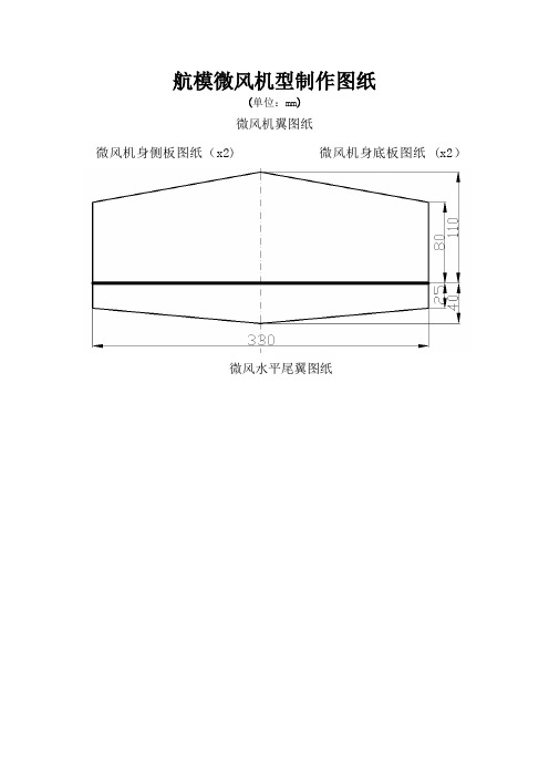
航模微风机型制作图纸
(单位:mm)
微风机翼图纸
微风机身侧板图纸(x2) 微风机身底板图纸 (x2)
微风水平尾翼图纸
微风垂直尾翼图纸
航模微风机型制作图纸从广告店做的KT板写真
用美工刀下料
用倒角刀开槽
机翼的处理方式
垂尾和加强片的制作
倒角处理过的机身精度非常好呀
假装一下
粘接机身
中间夹了一点竹条,增强机头强度,我就爱摔机头
粘接好的样子
尾翼前缘也加了竹条
塑料包装盒的直角部分
放在翼口加强正好
我的机翼是这么搞的
直角部分,机翼前缘有竹丝不用加强了。
前起落架的细节
起落架的总成
后起落架转向偏航总成
拉力线动力总成
作简单
了飞机的重心
舵机和双鱼线的链接,很大程度上减少了虚位
到现在为止,所有的地方都做好了,整体照片!。
航模图纸

3DX 3D Park Flyer Printing InstructionsThank you for downloading Foamy Factory’s 3DX 3D Park Flyer plans! To get the most out of your plans, please follow the following printing guide. If you have any questions, feel free to email me at tim@**Copyright Notice – The plans presented are freely distributed. These plans may be printed by commercial means for personal use only. These plans may not be used for commercial purposes of any sort without the written consent of Timothy Hart, Foamy Factory Models. (if you have any problems making copies at a commercial printer, show them this copyright notice)Due to variances in printers and printer drivers, there may be some size discrepancies in the final printed output. The prototype tiled plans were printed on a Canon BJC 2010 printer and came out within 1/32” of the final noted size. Small variances are OK and can be expected depending on printer used. As long as the overall dimensions are within about ½”, the plane will fly fine and it is nothing to worry about. I have tried to compensate for as many variables as possible, but it is impossible to test under all circumstances. Follow the guide and you will end up with plans that are very close, if not exact.First of all, make sure you have the latest version of Adobe Acrobat Reader. These plans are formatted for version 5. If you have an earlier version, go to and download the latest free Acrobat reader.To print tiled plans on 8.5x11” or A4 paper3dx-updated.pdf and 3dx-updated-a4.pdf - This pdf file is the same plan as the full sheet plan, but it is formatted to be printed on 16 tiled 8.5x11 inch or 20 A4 sheets of paper. First, print a test page of page 1. Check the inch scale at the bottom right of the page. If it is right on, and the margin box is showing all the way around, print all of the pages.If the margin box is not showing all the way around, check the “Auto-rotate and center pages” box. Make sure that it is the ONLY box checked in the “Copies and Adjustments” section of the print setup screen. Print a test page. Everything should be OK at this point. If everything is good, print all 18 pages. If there still major discrepancies, check your printer drivers and make sure they are updated. Also, check your printer properties and make sure you have the correct paper size selected.Putting it all togetherMake sure when taping the plans together, you line up the margin marks, not the edges of the paper. There should be 3 rows of 6 sheets of paper. Arrange the sheets by row. Very carefully cut along the right and top margin of the margin boxes. Then, tape the bottom row together, then the middle, then the top. Align the prints as close as possible using the margin boxes and the drawing. Then, once you have 3 rows taped together, align and tape the top of the bottom row to the bottom of the middle row of sheets. Then align and tape those to the bottom of the top row. Now you have a full sheet of 3DX plans! It sounds a bit complicated, but you’ll get it…Once I have that done, I make templates of the parts out of poster board and start cutting foam!Full Sheet Plans3dx-updated-fullsheet.pdf - This pdf file is formatted to be printed full size on 36x48 inch paper. Put this file on a disk, then take the disk to your local Kinko's or printing center. Print the plans directly from the file on the disk. Do not print this on a small sheet of paper then try to enlarge it. You will get very weird results.3dx-updated-A0.pdf - This pdf file is formatted to be printed on A0 paper. Put this file on a disk, then take it to your local Kinko's or printing center. Print the plans directly from the file on the disk.Make sure when printing that the "fit to page" or "center on page" checkbox is NOT checked in the print properties box for the printer when printing full sheet plans. Make sure you tell the clerk at the print shop the above info.Once the plans are printed, be sure to check the inch scale on the bottom left side of the plans. Not all printers handle files the same. Try to get the inch scale as close as possible. Also, check the wingspan. It should be 36” (or very close). I took the files to my local Kinko's printing center and the plans came out exact.If you have any questions, feel free to email me at tim@ Have fun and send some pictures of your completed model!Cheers,Tim Harttim@Copyright © 2003, All Rights Reserved, Foamy Factory Models。
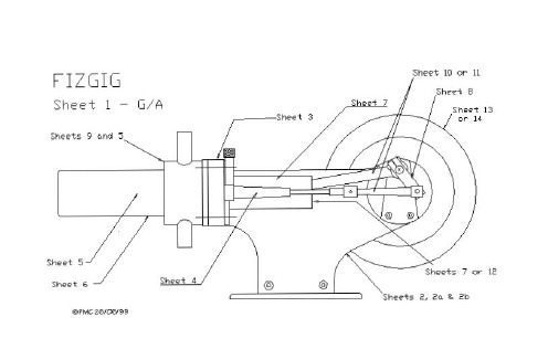
Stirling Engine Plans 斯特林发动机模型简易图纸
\」回3132'
斗护/泣T
回::J '
③
I
3 /3 2' To p 7M
E:>f MC 25i叫
⑩
FIZGIG
Shee 吃
12
Li gh 吃 weigh 吃
Pis 吃 on ,
'-'μ r ~ ~
@口
2
311 坦
>SSU E' 0 (B E'-t oJ
C C>n俨。d
M龟 w e e n
c e ntr e ~
Sheet 7
Cylinde 俨&
豆二
Pis 吃 on
@口
(8" 变 α 〉
37/6 ~
"♂
E
Lodite ω〉唁
( tetedr T
~-- Approx
See de~ωled no 飞 E for fit协 9 p'" 毛~ to cy们 nder
@
一一γ
→忖←
U~
'"
也旬'
白
S .,..,. Sh ee t II for
"' r . QOk . d
"" hol. . T Ip of 1/驴
, .啊<co肝脏 l
《 ?①
},
,-,
E
g
E:>, ~c …
FIZGIG
Issue 0
4
Sheet 2b (Be 吃 Q)
1110' or 2MN bedplQte 0 口
S ~ ve 俨 5old~r
3/1豆
航模图纸-KT板-上单翼-像真-F-22(All in one)

Bevel edges ofnozzles as shownBevel edges ofnozzles as shownFuselage top spine(Make 1)34 deg bevel (.15")34 deg bevel (.15")Aft fuselage bottom (Make 1)Vertical ta (Make 2Designed by SAll parts mad e from 6m foam unless othCopyright © 2007 peron control horns m 1/32" plywood)e plates for thrust oring motor mount 1 each from 1/8" ply)Epoxy to motor stick hereby Steve Sh umate m 6mm De pron or BlueCo re s otherwise specified 07 All Rig hts Reserved J i g f o r s e t t i n g t a i l d i h e d (M a k e63 de g b e v e l (.26")63 d e g b e v e l (.26")76 d e g b e v e l (.5")76 d e g b e v e l (.5")B e v e l a n d t r im a s r e q u i r e d t o f i tf l u s h w it h f u s e lag e s i d e s B e v e l a n d t r im a s r e q u i r e d t o f i t f l u sh wi t h f u s e l a g e s i d e s63 deg bevel (.26")Aft fuselage (Make 1 from 363 deg bevel (.2selage top piece from 3mm Depron)vel (.26")Trim pieces fo(Make 2ces for outboard of vertical t ail ake 2 from 3mm Depro n)Vertical tail (Make 2)Install aft fuselage sides hereVertical tail slot (cut at 28 deg angl e)t i n g v e r t i c a l i h e d r a l k e 2)S t a b i l a t o r p i v o t t u b (g r o o v e e d g e a n d a t w i t h e p o x y )Forward fuselage bottom (Make 1)Tab fits into slot in wingForward fuselage top (Make 1)Inlet d (Make 2 fThrust vector servo (HS-85MG shown)34 deg beStabilator servoTab fits into slot in wingAft fuselage side(Make 2)nlet diverter ke 2 from 3mm)Inboard inlet side (Make 2 from 3mm)Fuselage centerline s upportand motor mount (Make 2 and laminat e)34 deg bevel (.15")34 deg bevel (.15")34 deg bevel (.08")34 deg bevel (.08")eg bevel (.08")Cutout to clear rudder servoTail booms(Make 10 and laminate 5 each to make two boom s)Motor stick cutoutTemporary bulkhead to help position fusel age sides on wing during assembly (Make 4)Cut channel toclear stab pivot tubeTurtledeck top (Make 2)(this piece is slightly over size in width to allow trimmin g to shape)Optional launch grip fairings Make 2 and sand to shapeT5T4240Scale in inch2T1inches4T1T2Nose cone top template (use to help carve to shape)Cut slot for fuselagecenter spine Install aft fuselage sides hereCut slot for fucenter spiT3Wing (Make 1)Vertical tail bracesfor fuselage er spineT4T528 deg bevel (.12")S t a b i l a t o r p i v o t t u b e s (g r o o v e e d g e a n d a t t a c h w i t h e p o x y )t t u b e s d a t t a c hForward fuselageF234 d eg bev el (.15")29 d e g be v e l (.12")Canopy(Make 10 and laF3Forward fuselage sid elower half(Make 2)34 deg bevel (.15")34 de g b eve l (.15")F2F3F4 Forward fuselage sid eupper half(Make 2)29 d e g b e v e l (.12")nopynd laminate)T1T1T3T2F1F3Cut bulkhead in half along this line before assembly (will re-attachduring assembly)F2Cut bulkhead in half along this line before assembly (will re-attachduring assembly)Cut bulkhead in half along this line before assembly (will re-attachduring assembly)F4。
航空发动机原理图文解析

航空发动机原理--螺桨风扇发动机螺桨风扇发动机是一种介于涡轮风扇发动机和涡轮螺旋桨发动机之间的一种发动机形式,其目标是将前者的高速性能和后者的经济性结合起来,目前正处于研究和实验阶段。
螺桨风扇发动机的结构见图,它由燃气发生器和一副螺桨-风扇(因为实在无法给这个又象螺旋桨又象风扇的东东起个名字,只好叫它螺桨-风扇)组成。
螺桨-风扇由涡轮驱动,无涵道外壳,装有减速器,从这些来看它有一点象螺旋桨;但是它的直径比普通螺旋桨小,叶片数目也多(一般有6~8叶),叶片又薄又宽,而且前缘后掠,这些又有些类似于风扇叶片。
根据涡轮风扇发动机的原理,在飞行速度不变的情况下,涵道比越高,推进效率就越高,因此现代新型不加力涡轮风扇发动机的涵道比越来越大,已经接近了结构所能承受的极限;而去掉了涵道的涡轮螺旋桨发动机尽管效率较高,但由于螺旋桨的速度限制无法应用于M0.8~M0.95的现代高亚音速大型宽体客机,螺桨风扇发动机的概念则应运而生。
由于无涵道外壳,螺桨风扇发动机的涵道比可以很大,以正在研究中的一种发动机为例,在飞行速度为M0.8时,带动的空气量约为内涵空气流量的100倍,相当于涵道比为100,这是涡轮风扇发动机所望尘莫及的,将其应用于飞机上,可将高空巡航耗油率较目前高涵道比轮风扇发动机降低15%左右。
同涡轮螺旋桨发动机相比,螺桨风扇发动机的可用速度又高很多,这是由它们叶片形状不同所决定的。
普通螺旋桨叶片的叶型厚度大以保证强度,弯度大以保证升力系数,从剖面来看,这种叶型实际上就是典型的低速飞机的机翼剖面形状,它在低速情况下效率很高,但一旦接近音速,效率就急剧下降,因此装有涡轮螺旋桨发动机的飞机速度限制在M0.6~M0.65左右;而螺桨-风扇的既宽且薄、前缘尖锐并带有后掠的叶型则类似于超音速机翼的剖面形状,这种叶型的跨音速性能就要好的多,在飞行速度为M0.8时仍有良好的推进效率,是目前新型发动机中最有希望的一种。
当然,螺桨风扇发动机也有其缺点,由于转速较高,产生的振动和噪音也较大,这对舒适性有严格要求的客机来讲是一个难题。
航模北极星水机分割图纸
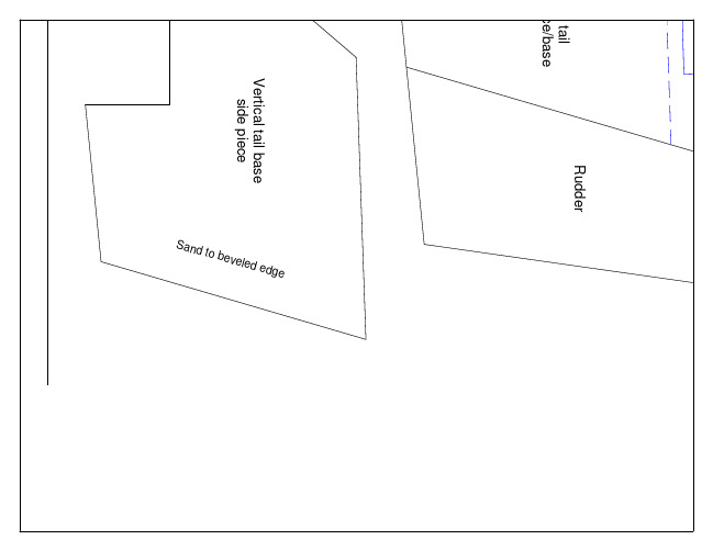
Vertical tail base side piece
Sand
to be veled edge
Scale in inches 0 2 4
Aileron
F3
Aft Fuselage Bottom
F3
1
2" /3
p
2 /3 1
pl "
y
s ar sp
(
Wing
Cut slot for rudder servo
Control Horn Make 2 from 1/32" ply
se support rtical tail ba 2" ply Ve m 1/3 Make 1 fro
Tip floats Make 10
Canopy outline for reference
Copyright © 2008
Designed by Steve Shumate
Nosecone top template
Motor mount Make 1 from 1/8" ply
rs
(c
ut
i ot sl
n
g in w
tube main spar
th wi
fe ni k
d an
ll ta s in
ith w
y ox ep
)
ery tray a Install batt
nding
N1
F3
F2
3/8" strip on aft side
F1
Motor Battery Tray
F1
Start bending here
1 /3 2 " pl y
航模零基础系列:发动机

学航模零基础系列教程发动机CattleCattle带您进入航模的世界!Cattle与您一路同行,让我们从今天开始吧!戏说发动机V1.2发动机,看到这个,第一感觉那可真是一个大的不得了的工程,既然是一个不得了的工程,想要说清楚,讲个明白那可得有一本牛津大字典的容量了。
不过咱这不是科学普及嘛,就得篇幅少,通俗易懂点不是,这可真是一个抓耳挠腮,较劲脑汁的问题。
废话少说了,言归正传。
今天就写点科学普及的故事吧!欢迎拍砖了。
既然是故事,咱就言简意赅,主要让大家有个感性的总体认识。
看着有点意思呢,就接着看,看着想拍桌子了,就拍下桌子,看着枯燥了,就睡个觉,看着糊涂了尽管问。
看着不耐烦了呢,也提个醒,我也好不再烦人。
(1)发动机篇小时候望着蓝天、白云,还有那翱翔天空的白鸽,俺就想了什么时候俺也能上天呢?还记得小时候玩的那个小玩具,姑且叫它愤怒的小鸟吧。
“我是一只小小鸟,想要飞却飞不高啊”这样旋转的“机翼”就成为旋翼,旋翼产生升力就是直升机可以垂直起落的基本原理,这也许就是最早的飞行模型吧!这也是人们在跳出了小鸟拍翅飞行之谜后,利用伯努利空气动力升力原理,用科学理论掀开的历史伟大一页!曾经多才多艺的达·芬奇他老人家也设计过一个类似的飞机模型,不过还是没有超越纸上谈兵的地步。
还是莱特兄弟靠谱,在历史上留下了重要一笔(据说中国的冯如也是第一个飞上蓝天的,当然了嫦娥就不说了,孰是孰非就不争了,作为中国人,反正我信了)。
飞机的发展历史就不多说了,再说就跑题了,有一千零一夜的时候再续了。
鸟儿能飞,因为她有一双翱翔的翅膀,飞机能飞,因为它有一颗强大的心脏----发动机。
现代的发动机,不管是涡轮、涡轴、还是涡扇、涡喷。
其本质都是一样的,都是热力发动机。
根据伟大的牛顿爵士第三定律—作用力与反作用力,还有一堆天书般的公式与经验公式,总之,经过热能与动能的转换,加热、压缩的空气就成了发动机的推进动力。
发动机发展至今,其基本组件还是那几个,就像人一样,相貌虽不同,但总归咋一看还都是有鼻子有眼的。
航模图纸-KT板-上单翼-像真-Su-37(All in one)

ns e r t 6g n d eNacelle t op doubler 2(Make 4)Nacelle botto m doubler 1 - In board(Make 2)NaceNacelle t op double r 1(Make 4)Fuselage side rails(Make 4)boardNacelle bottom doubler 2 - Inboard(Make 2)All parDesCopyTrim off this part if using single motorCenterline spike(Make 1)ll parts made fro m 6mm Depron or Bl ueCore foam unless other wise specifiedDesigned by Steve Shum ate Copyright © 2007 All Rights Reser vedInboard nacelle side (Make 2)Outboard nacelle side (Make 2)Nacelle bottom (Make 2)Forward fuselage bottom (Make 1)Trim as shown for twin motor i .75" square x 1/16" ply bearing supports.75" square x 1/16" ply bearing supportsD a s h e d r e d l i n e s h o w s t i p f o r S u -30 v a r i a n t sotor installationVertical tail (Make 2)R e d d a s h e d l in e s in d i c a t e s t r a k e d e s i g n f o r n o n -c a n a r d S u -30 v a r i a n t sStab (Mak(makStabilator control horn (Make 2 from 1/16" ply)Stabilator control horn doublers/end stops (Make 6 from 1/16" ply)1/2" dia.Rudder control horns (make 2 from 1/32" plywo od)I n s e r t 6m m x 11.5"1/32" p l y s p a r i n s lo t f or e x t r a s t r e n g t h (o p t )Glue one doubler to control horn as shownNote: If using a motor other tha n the LSPJ, modify the height of the side pla tes to ensure the centerline of the motor is al igned with the pivot bolt (to minimize strain on the servo)Epoxy to motor stick here Epoxy to motor stick hereO u t b o a r d Insert 1/32" p spar inside sl (6mm x 4.0"。