网络实验三
实验三 常见网络命令的使用
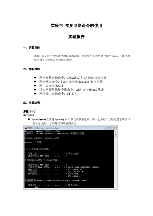
实验三常见网络命令的使用实验报告一、实验目的理解、验证常用网络命令的原理和功能,掌握常用的网络命令使用方法,合理使用相关命令对网络进行管理与维护二、实验内容●网络参数查询命令:IPCONFIG和IP地址相关计算●网络测试命令:Ping 命令和Tracert命令检测●路由表命令ROUTE●以太网硬件地址查询命令:ARP 命令和MAC绑定●网络端口查询命令:NETSTAT三、实验过程步骤(一)IPCONFIG⏹ipconfig——当使用ipconfig时不带任何参数选项,那么它为每个已经配置了的接口显示ip地址、子网掩码和缺省网关值。
⏹ipconfig /all——当使用all 选项时,ipconfig能为dns 和wins 服务器显示它已配置且所要使用的附加信息(如ip地址等),并且显示内置于本地网卡中的物理地址(mac)。
如果ip地址是从dhcp服务器租用的,ipconfig将显示dhcp服务器的ip地址和租用地址预计失效的日期。
实验步骤(二)ping命令⏹ping 127.0.0.1⏹-t。
引导ping继续测试远程主机直到按Ctrl+C中断该命令。
⏹-n count。
缺省情况下,ping发送四个ICMP包到远程主机,可以使用-n参数指定被发送的包的数目。
⏹-l length。
使用-l参数指定ping传送到远程主机的ICMP包的长度。
缺省情况下,ping发送长度为32bytes的包。
-f。
使ping 命令在每个包中都包含一个Do Not Fragment(不分片)的标志,它禁止包(packet)经过的网关把packet分片。
⏹-i ttl。
设定Time To Live(存活时间)。
用ttl 指定其值。
实验步骤(三)tracert命令⏹tracert 202.114.32.1实验步骤(四)ROUTE命令⏹route change——你可以使用本命令来修改数据的传输路由,不过,你不能使用本命令来改变数据的目的地。
计算机网络实验三参考答案

1. What is the IP address and TCP port number used by the client computer (source) that is transferring the file to ? To answer this questio n, it’s probably easiest to select an HTTP message and explore the details of the TCP packet used to carry this HTTP message, using the “details of the selected packet header window” (refer to Figure 2 in the “Getting Started with Wireshark” Lab if you’re uncertain about the Wireshark windows).Ans: IP address:192.168.1.102 TCP port:11612. What is the IP address of ? On what port number is it sending and receiving TCP segments for this connection?Ans: IP address:128.119.245.12 TCP port:80If you have been able to create your own trace, answer the following question:3. What is the IP address and TCP port number used by your client computer(source) to transfer the file to ?ANS: IP address :10.211.55.7 TCP port:492654. What is the sequence number of the TCP SYN segment that is used to initiate the TCP connection between the client computer and ? What is it in the segment that identifies the segment as a SYN segment?ANS: sequence number: 0 Syn Set = 1 identifies the segment as a SYN segment5. What is the sequence number of the SYNACK segment sent by to the client computer in reply to the SYN? What is the value of the ACKnowledgement field in the SYNACK segment? How did determine that value? What is it in the segment that identifies the segment as a SYNACK segment?ANS: The sequence number: 0ACKnowledgement number : 1 which is sequence number plus 1Both the sequence flag and the ACKnowledgement flag been set as 1, identifies the segment as SYNACK segment.6. What is the sequence number of the TCP segment containing the HTTP POST command? Note that in order to find the POST command, you’ll need to dig into the packet content field at the bottom of the Wireshark window, looking for a segment with a “POST” within its DATA field.Ans: The sequence number : 17. Consider the TCP segment containing the HTTP POST as the first segment in the TCP connection. What are the sequence numbers of the first six segments in the TCP connection (including thesegment containing the HTTP POST)? At what time was each segment sent? When was the ACK for each segment received? Given the difference between when each TCP segment was sent, and when its acknowledgement was received, what is the RTT value for each of the six segments? What is the EstimatedRTT value (see page 249 in text) after the receipt of each ACK? Assume that the value of the EstimatedRTT is equal to the measured RTT for the first segment, and then is computed using the EstimatedRTT equation on page 249 for all subsequent segments.Note: Wireshark has a nice feature that allows you to plot the RTT for each of the TCP segments sent. Select a TCP segment in the “listing of captured packets” window that is being sent from the client to the server. Then select: Statistics->TCP Stream Graph- >Round Trip Time Graph.Segment 1 Segment 2 Segment 3Segment 4Segment 5Segment 6After Segment 1 : EstimatedRTT = 0.02746After Segment 2 : EstimatedRTT = 0.875 * 0.02746 + 0.125*0.035557 = 0.028472 After Segment 3 : EstimatedRTT = 0.875 * 0.028472 + 0.125*0.070059 = 0.033670 After Segment 4 : EstimatedRTT = 0.875 * 0.033670 + 0.125*0.11443 = 0.043765 After Segment 5 : EstimatedRTT = 0.875 * 0.043765 + 0.125*0.13989 = 0.055781 After Segment 6 : EstimatedRTT = 0.875 * 0.055781 + 0.125*0.18964 = 0.072513 8. What is the length of each of the first six TCP segments?(see Q7)9. What is the minimum amount of available buffer space advertised at the received for the entire trace? Does the lack of receiver buffer space ever throttle thesender?ANS:The minimum amount of buffer space (receiver window) advertised at for the entire trace is 5840 bytes;This receiver window grows steadily until a maximum receiver buffer size of 62780 bytes.The sender is never throttled due to lacking of receiver buffer space by inspecting this trace.10. Are there any retransmitted segments in the trace file? What did you check for (in the trace) in order to answer this question?ANS: There are no retransmitted segments in the trace file. We can verify this by checking the sequence numbers of the TCP segments in the trace file. All sequence numbers are increasing.so there is no retramstmitted segment.11. How much data does the receiver typically acknowledge in an ACK? Can youidentify cases where the receiver is ACKing every other received segment (seeTable 3.2 on page 257 in the text).ANS: According to this screenshot, the data received by the server between these two ACKs is 1460bytes. there are cases where the receiver is ACKing every other segment 2920 bytes = 1460*2 bytes. For example 64005-61085 = 292012. What is the throughput (bytes transferred per unit time) for the TCP connection? Explain how you calculated this value.ANS: total amount data = 164091 - 1 = 164090 bytes#164091 bytes for NO.202 segment and 1 bytes for NO.4 segmentTotal transmission time = 5.455830 – 0.026477 = 5.4294So the throughput for the TCP connection is computed as 164090/5.4294 = 30.222 KByte/sec.13. Use the Time-Sequence-Graph(Stevens) plotting tool to view the sequence number versus time plot of segments being sent from the client to the server. Can you identify where TCP’s slow start phase begins and ends, and where congestion avoidance takes over? Comment on ways in which the measured data differs from the idealized behavior of TCP that we’ve studied in the text.ANS: Slow start begins when HTTP POST segment begins. But we can’t identify where TCP’s slow start phase ends, and where congestion avoidance takes over.14. Answer each of two questions above for the trace that you have gathered when you transferred a file from your computer to ANS: Slow start begins when HTTP POST segment begins. But we can’t identify where TCP’s slow start phase ends, and where congestion avoidance takes over.。
计算机网络-实验3-可靠数据传输协议-GBN协议的设计与实现

实验3:可靠数据传输协议-GBN协议的设计与实现
1.实验目的
理解滑动窗口协议的基本原理;掌握GBN的工作原理;掌握基于UDP设计并实现一个GBN协议的过程与技术。
2.实验环境
接入Internet的实验主机;
Windows xp或Windows7/8;
开发语言:C/C++(或Java)等。
3.实验内容
1)基于UDP设计一个简单的GBN协议,实现单向可靠数据传输(服务器到客户的数据传输)。
2)模拟引入数据包的丢失,验证所设计协议的有效性。
3)改进所设计的GBN协议,支持双向数据传输;
4.实验设计
1)Client:
函数列表:
各函数功能:
状态转换图:
2)Server:
状态转换图:
3)数据包结构:
发送方:数据包包括序列号与内容接收方:只含接收到的数据包的序号
5.实验结果1)Client:
2)Server:
详细对照:。
网络安全协议分析实验3_TCP_SYN扫描_协议分析TCP_ACK扫描_协议分析
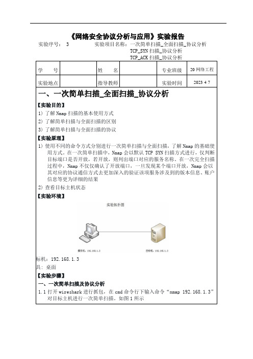
《网络安全协议分析与应用》实验报告实验序号: 3 实验项目名称:一次简单扫描_全面扫描_协议分析TCP_SYN扫描_协议分析TCP_ACK扫描_协议分析学号姓名专业班级20网络工程实验地点指导教师实验时间2023-4-7 一、一次简单扫描_全面扫描_协议分析【【实验目的】1)了解Nmap扫描的基本使用方式2)了解简单扫描与全面扫描的区别3)了解简单扫描与全面扫描的协议【实验原理】1)使用不同的命令方式分别进行一次简单扫描与全面扫描,了解Nmap的基础使用方式。
在一次简单扫描中,Nmap会以默认TCP SYN扫描方式进行,仅判断目标端口是否开放,若开放,则列出端口对应的服务名称。
在一次完全扫描过程中,Nmap不仅仅确认了开放端口,一旦发现某个端口开放,Nmap会以其对应的协议通信方式去更加深入的验证该项服务涉及到的版本信息、账户信息等更为详细的结果2)查看目标主机状态【【实验环境】目标机:192.168.1.3工具: 桌面【【实验步骤】一、一次简单扫描及协议分析1.1打开wireshark进行抓包,在cmd命令行下输入命令“nmap 192.168.1.3”对目标主机进行一次简单扫描。
如图1所示图11.2可以看到目标主机有许多tcp端口处于开放状态,SERVICE一栏显示了各端口对应的服务。
切换到wireshark,在过滤器中输入:ip.addr == 192.168.1.3,确定。
如图2所示图21.3通过wireshark抓包可以看到一次简单扫描为TCP SYN扫描方式,我们针对其对目标机445端口的扫描进行分析(其余端口请自行分析)。
Nmap由本地端口46062向目标机的445端口发送TCP SYN数据包请求连接。
如图3所示图31.4目标机接收到来自扫描机的TCP请求之后向其46062端口发送SYN,ACK确认包。
如图4所示图41.5扫描机向目标机发送RST数据包进行连接复位,目标机清除445连接。
计算机网络上机实验三
实验:二层以太网组网和交换机的配置实验一:二层以太网组网实验【实验目的】1. 了解局域网各组成部分。
2. 掌握网络设备类型选择、软硬件设置方法。
3. 掌握基本的网络故障的判断、解决方法。
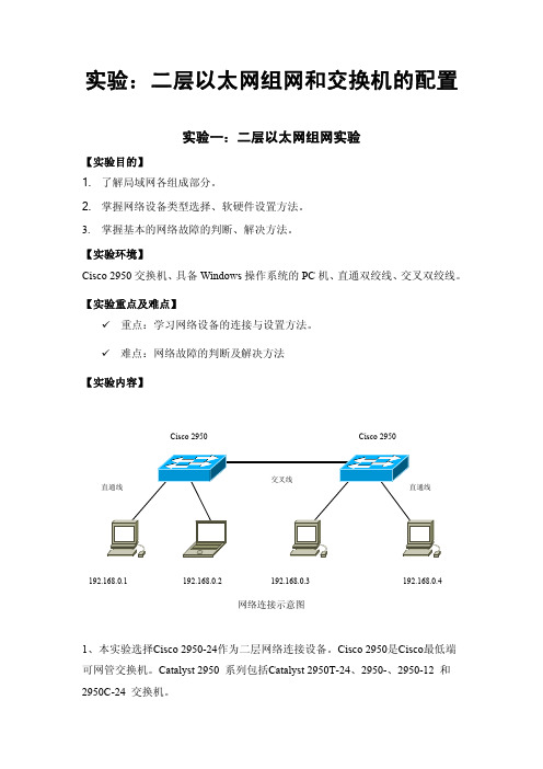
【实验环境】Cisco 2950交换机、具备Windows 操作系统的PC 机、直通双绞线、交叉双绞线。
【实验重点及难点】9 重点:学习网络设备的连接与设置方法。
9 难点:网络故障的判断及解决方法【实验内容】网络连接示意图1、本实验选择Cisco 2950-24作为二层网络连接设备。
Cisco 2950是Cisco 最低端可网管交换机。
Catalyst 2950 系列包括Catalyst 2950T-24、2950-、2950-12 和2950C-24 交换机。
192.168.0.4 192.168.0.1 192.168.0.2 192.168.0.3 Cisco 2950 Cisco 2950Catalyst 2950-24 交换机有24 个10/100 端口;2950-12 有12 个10/100 端口;2950T-24 有24个10/100 端口和2 个固定10/100/1000 BaseT 上行链路端口;2950C-24 有24 个10/100 端口和2 个固定100 BaseFX 上行链路端口。
本次实验不考虑对交换机进行设计,只按照交换机的默认设置。
按照如上连接图进行网络连接。
具体连接过程如下:1)Cisco 2950交换机连接,将两台交换机接通电源,系统自检正常以后,任意选择两个交换机的端口,通过交叉线进行连接。
2)将如图PC机及笔记本加电,并通过直通线分别接入各交换机,观察各接入端口,待端口为绿色是为正常。
Cisco 2950交换机的端口在接入PC机时,其端口有30秒的测试过程,此过程中状态灯为黄色,若端口检测正常,则会转变为绿色。
在此步骤中思考以下问题:1)实验中Cisco 2950加电启动的过程?2)Cisco 2950交换机端口数是多少?3)Cisco 2950在接入设备时状态灯的变化过程。
实验三交换式以太网的组建

实验三交换式以太⽹的组建实验三交换式以太⽹的组建⼀、实验⽬的通过实训使学⽣掌握计算机局域⽹的⽹络配置与测试⽅法。
⼆、实验设备WIN2000计算机、局域⽹环境、交换机。
三、实验内容IP地址设置、⽹络测试四、实验步骤(⼀)Windows 2000/⽹络配置:IP地址配置⼀般情况下,中⽂Windows 2000会按照系统默认的⽅式设置本地连接的属性,我们需要根据实际情况设置TCP/IP协议,步骤如下:1.当⽹卡正确安装完后,您会发现在桌⾯上出现了⼀个“⽹上邻居”图标,⽤右键单击它并选中“属性”。
2.在“⽹络和拨号连接”窗⼝中⽤右键单击“本地连接”图标,并选中“属性”。
3.选择“本地连接属性”对话框中的“Internet协议(TCP/IP)”项,并单击“属性”按钮。
4.在“Internet 协议(TCP/IP)属性”对话框中,选择“使⽤下⾯的IP地址”选项,依次输⼊⽹络中⼼提供给你的IP地址(202.***.***.***)、⼦⽹掩码(255.255.255.***)、默认⽹关(202.113.96.2);再选择“使⽤下⾯的DNS服务器地址”选项,添⼊⽹络中⼼DNS 服务器地址(202.113.96.10)。
5.按“确定”结束TCP/IP设置。
到此,您就已经完成了上⽹所需的⽹络配置。
(⼆)Windows 2000/⽹络配置:⽹络测试当进⾏完⽹络的配置后,如果⼀切正常的话,⽤户的计算机应该与校园⽹连通了,接下来就可以使⽤⼀些常见的Internet服务了。
测试⽹络连通情况时,通常使⽤ping命令。
在Windows 2000环境中,从【开始】,选【运⾏(R)】项,在【运⾏】对话框中输⼊“cmd”后单击“确定”按钮,进⼊DOS环境下。
运⾏ping命令检测⽤户计算机与⽹关(路由器)的连通情况。
1.请先检测局域⽹的⽹关,例如:某局域⽹的⽹关为202.200.48.129,则运⾏命令:ping 202.200.48.129 ,如果⽹关连通正常,则出现如下信息,如图:如果⽹关不通,则会出现如下的信息:Request timed out.Request timed out.Request timed out.Request timed out.那么,请您仔细检查您的⽹卡安装及⽹络配置是否正确。
计算机网络实验 实验三 PAP、chap认证
步骤1.基本配置 Red-Giant(config)# hostname Ra 由器主机名Ra Ra(config)# Red-Giant(config)# hostname Rb 由器主机名Rb 配置路
配置路
对路由器Ra进行的配置
Ra(config)# interface serial 1/3 Ra(config-if)# ip address 172.16.2.1 255.255.255.0 配置接口地址 Ra(config-if)# no shutdown Ra# show int serial 1/3
对Rb进行配置
Rb(config)# interface serial 1/3 ( DCE), DTE Rb(config-if)# ip address 172.16.2.2 255.255.255.0 Rb(config-if)# clock rate 64000 (DCE端进行 时钟配置) Rb(config-if)# no shutdown
验证测试
注意事项:先关掉电源开关,然后打开,再调 试debug命令。 Ra# debug ppp authentication 观察pap验证 过程 Rb# debug ppp authenticationຫໍສະໝຸດ 步骤2.配置PPP PAP认证
Rb(config)# username Ra password 0 star ! 在验证方配置被验证方用户名、密码 Ra(config-if) # encapsulation ppp 接口 下封装PPP协议 Ra(config-if) # ppp pap sent-username Ra password 0 star ! PAP认证的用户名、密码 Rb(config-if)# encapsulation ppp Rb(config-if)# ppp authentication pap ! ppp 启用pap认证方式
计算机网络实验报告实验3
计算机网络实验报告实验3一、实验目的本次计算机网络实验 3 的主要目的是深入理解和掌握计算机网络中的相关技术和概念,通过实际操作和观察,增强对网络通信原理、协议分析以及网络配置的实际应用能力。
二、实验环境本次实验在计算机网络实验室进行,使用的设备包括计算机、网络交换机、路由器等。
操作系统为 Windows 10,实验中使用的软件工具包括 Wireshark 网络协议分析工具、Cisco Packet Tracer 网络模拟软件等。
三、实验内容与步骤(一)网络拓扑结构的搭建使用 Cisco Packet Tracer 软件,构建一个包含多个子网的复杂网络拓扑结构。
在这个拓扑结构中,包括了不同类型的网络设备,如交换机、路由器等,并配置了相应的 IP 地址和子网掩码。
(二)网络协议分析启动 Wireshark 工具,捕获网络中的数据包。
通过对捕获到的数据包进行分析,了解常见的网络协议,如 TCP、IP、UDP 等的格式和工作原理。
观察数据包中的源地址、目的地址、协议类型、端口号等关键信息,并分析它们在网络通信中的作用。
(三)网络配置与管理在实际的网络环境中,对计算机的网络参数进行配置,包括 IP 地址、子网掩码、网关、DNS 服务器等。
通过命令行工具(如 Windows 中的 ipconfig 命令)查看和验证配置的正确性。
(四)网络故障排查与解决设置一些网络故障,如 IP 地址冲突、网络连接中断等,然后通过相关的工具和技术手段进行故障排查和解决。
学习使用 ping 命令、tracert 命令等网络诊断工具,分析故障产生的原因,并采取相应的解决措施。
四、实验结果与分析(一)网络拓扑结构搭建结果成功构建了包含多个子网的网络拓扑结构,各个设备之间能够正常通信。
通过查看设备的状态指示灯和配置信息,验证了网络连接的正确性。
(二)网络协议分析结果通过 Wireshark 捕获到的数据包,清晰地看到了 TCP 三次握手的过程,以及 IP 数据包的分片和重组。
计算机网络实验三:路由器的配置评分标准
实验三:路由器的配置评分标准若实验报告每一项内容基本达到以下要求则可评为80分,95分封顶,实验报告总分为:实验过程及结果得分*80%+实验总结*20%。
一旦发现抄袭现象,则总分一律评为50分以下。
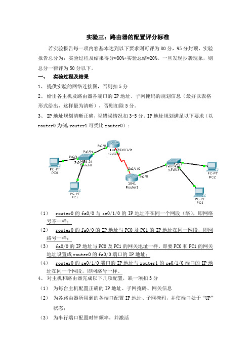
一、实验过程及结果1、提供实验的网络连接图,否则扣5分2、给出各主机及路由器各端口的IP地址、子网掩码的规划信息(最好以表格形式给出,这样最为清晰),否则扣除5分。
3、IP地址规划清晰正确,视错误情况扣3-5分。
IP地址规划满足以下要求(以router0为例,router1可类比router0):(1)router0的fa0/0与se0/1/0的IP地址不在同一个网段(络),即网络号不一样;(2)router0的fa0/0的IP地址与PC0及PC1的IP地址在同一网段,即网络号一样;(3)fa0/0的IP地址与PC0及PC1的网关地址一样。
即要PC0和PC1的网关地址设置成router0的fa0/0端口的IP地址;(4)router0的se0/1/0端口的IP地址与router1的se0/1/0端口的IP地址在同一个网段,即网络号一样。
4、对主机和路由器完成以下几项配置,缺一项扣3分(1)为每台主机配置正确的IP地址、子网掩码、网关信息(2)为各路由器所用到的各端口配置IP地址、子网掩码,并使端口处于“UP”状态;(3)为串行端口配置时钟频率,并激活(4)为各路由器配置路由信息协议(RIP)(5)使用show ip route查看路由器的路由表情况,并解释5、路由器的各项配置均有配置过程截图(只保留有用和正确的部分,图片文字能看的清,大小缩放合适)或文字形式的详细的配置命令。
若配置命令不完全、存在错误,视缺失和错误情况酌情扣3-6分6、对截图或配置过程进行必要的文字说明(忌啰嗦),即交代实验原理、思路、实验设计的想法等。
否则酌情扣2-3分6、有实验结果验证及说明,否则扣5分7、实验过程阐述思路清晰,有调理。
实验三 虚拟局域网配置

实验三虚拟局域网配置在当今数字化的时代,网络技术的发展日新月异,虚拟局域网(VLAN)作为一种重要的网络技术,为企业和组织的网络管理带来了诸多便利。
本次实验的主要目的就是深入了解并掌握虚拟局域网的配置方法,通过实际操作来加深对其原理和应用的理解。
虚拟局域网(Virtual Local Area Network,简称 VLAN)是一种将物理网络划分成多个逻辑网络的技术。
它可以在不改变物理拓扑结构的情况下,根据不同的需求将网络中的设备划分到不同的 VLAN 中,从而实现网络的隔离和优化。
在开始实验之前,我们需要准备好以下实验设备和环境:1、若干台支持 VLAN 功能的交换机。
2、若干台计算机。
3、网络连接线若干。
接下来,让我们逐步进行虚拟局域网的配置。
第一步,规划 VLAN 。
首先要明确我们需要划分的 VLAN 数量以及每个 VLAN 所包含的设备。
例如,我们可以将一个公司的网络划分为财务部 VLAN、市场部 VLAN、研发部 VLAN 等。
每个部门的设备将被分配到相应的VLAN 中,以实现部门之间的网络隔离和数据安全。
第二步,连接设备。
将计算机通过网络连接线连接到交换机的端口上。
确保连接稳定,并且设备之间能够正常通信。
第三步,进入交换机的配置模式。
通过控制台或者远程登录的方式,进入交换机的管理界面。
第四步,创建 VLAN 。
在交换机的配置命令中,使用特定的命令来创建 VLAN 。
例如,“vlan 10”表示创建 VLAN 10 。
为每个需要的VLAN 重复此操作。
第五步,将端口分配到 VLAN 。
指定哪些端口属于哪个 VLAN 。
这可以通过将端口设置为特定 VLAN 的访问模式来实现。
比如,“interface GigabitEthernet 0/1”进入端口配置模式,然后“switchport access vlan 10”将该端口分配到 VLAN 10 。
第六步,配置 VLAN 间的通信。
如果需要不同 VLAN 之间进行通信,还需要配置 VLAN 间的路由功能。
计算机网络原理实验三winsock套接字编程实验报告

实验三、WINSOCK套接字编程实验报告序号:姓名:学号:成绩1.实验目的:用C或JA V A语言编写客户端、服务器程序,实现基于TCP或UDP的网络通信数据传输服务,熟悉基于TCP或UDP的Socket编程原理。
2.实验环境:建立在TCP/IP 网络体系结构之上计算机网络实验环境。
各计算机除了安装TCP/IP 软件外,还安装了TCP/IP 开发系统。
计算机具备Windows环境中套接字socket 的编程接口功能,可为用户提供全网范围的进程通信功能。
3.实验指导:参见套接字编程实验指导4.实验步骤(1)运行指导书中给出的参考程序,分析实验结果,并回答问题(1)-(3)运行结果:(2)根据给定参考程序修改代码,完善修改服务器和客户端的功能。
并回答问题(4)-(5)5.实验结果分析(1)为什么在服务器和客户端要包含winsock2.h文件?答:因为在服务器和客户端的程序中要使用WinSock库中的函数如WSACleanup()等,必须包含头文件winsock2.h。
(2)为什么在服务器和客户端程序中要加入#pragma comment(lib,"ws2_32.lib") 语句,如果不加会出现什么问题?答:语句#pragma comment(lib, "Ws2_32.lib ")表示链接Ws2_32.lib这个库,在服务器和客户端程序中使用到了Ws2_32.lib中的相关函数,如果不加入这个语句,开发环境就无法解析一些Ws2_32.lib中的符号。
删除#pragma comment(lib,"ws2_32.lib") 语句后的运行结果:(3)为什么在服务器和客户端程序中要使用WSAStartup函数,如果不用,程序会有什么问题?答:在利用套接字编程时,第一步需要通过WSAStartup函数来加载套接字库,如果不使用WSAStartup函数就不能够建立套接字,因而无法建立服务连接。
西工大计算机网络实验三

实验报告实验名称--SOCKET编程一、实验目的(1)加深对TCP和UDP的理解;(2)实现两台计算机之间TCP/UDP通信。
二、实验过程原理:socket是在应用层和传输层之间的一个抽象层,它把TCP/IP层复杂的操作抽象为几个简单的接口供应用层调用以实现进程在网络中通信。
如下图所示:TCP通信原理如图:代码:服务器端:#pragma comment(lib, "WS2_32.lib")#include<Winsock2.h>#include<iostream>#include<stdlib.h>using namespace std;int main(){int i=0;WSADATA wsaData;SOCKET oldSocket,newSocket;//客户地址长度int iLen=0;//发送的数据长度int iSend=0;//接收的数据长度int ircv =0;//处世要发送给客户的信息char buf[20]="I am a server";//接收来自用户的信息char fromcli[512];//客户和服务器的SOCKET地址结构struct sockaddr_in ser,cli;if(WSAStartup(MAKEWORD(2,2),&wsaData)!=0){cout<<"failed to load winsock"<<endl;return 0;}cout<<"server waiting"<<endl;cout<<"---------------"<<endl;//创建服务器端帧听SOCKEToldSocket=socket(AF_INET,SOCK_STREAM,0);if(oldSocket==INVALID_SOCKET){cout<<"socket() failed:"<<WSAGetLastError()<<endl;return 0;}//以下是建立服务器端的SOCKET地址结构ser.sin_family=AF_INET;ser.sin_port=htons(5050);//使用系统指定的ip地址INADDR_ANY// ser.sin_addr.s_addr=htonl(INADDR_ANY);ser.sin_addr.s_addr= inet_addr("192.168.8.58");if(bind(oldSocket,(LPSOCKADDR)&ser,sizeof(ser))==SOCKET_ERROR) {cout<<"bind() failed:"<<WSAGetLastError()<<endl;return 0;}//进入侦听状态if(listen(oldSocket,5)==SOCKET_ERROR){cout<<"listen() failed:"<<WSAGetLastError()<<endl;return 0;}//接收客户端的连接iLen=sizeof(cli);newSocket=accept(oldSocket,(struct sockaddr*)&cli,&iLen);//产生一个新的SOCKETif(newSocket==INVALID_SOCKET){cout<<"accept() failed:"<<WSAGetLastError()<<endl;//return 0;}//进入一个无限循环,等待客户发送数据while(1){i++;//服务器初始化接收缓冲区memset(fromcli,0,512);ircv=recv(newSocket,fromcli,sizeof(fromcli),0);if(ircv==SOCKET_ERROR){cout<<"rcv() failed:"<<WSAGetLastError()<<endl;break;}else if(ircv==0)break;else {cout<<"-----服务器接收的内容为--------"<<fromcli<<endl;}if(strcmp(fromcli,"quit")==0)break;}closesocket(newSocket);closesocket(oldSocket);WSACleanup();}客户端:#pragma comment(lib, "WS2_32.lib")#include<winsock2.h>#include<iostream>#include<stdio.h>using namespace std;#define DATA_BUFFER 512int main(){WSADATA wsaData;SOCKET sClient;char ch;int i=0;char *Serip="192.168.8.58";//随着程序所在主机的地址改变而改变int SeriPort=5050;//从服务器接收的数据的长度int iLen;//发送的数据长度int isnd;//接收缓冲区char buf[DATA_BUFFER];//发送缓冲区char sndbuf[DATA_BUFFER];//服务器端SOCKET地址结构struct sockaddr_in ser;//接收/发送缓冲区的初始化memset(buf,0,sizeof(buf));memset(sndbuf,0,DATA_BUFFER);if(WSAStartup(MAKEWORD(2,2),&wsaData)!=0){cout<<"failed to load winsock"<<endl;return 0;}//填写要连接的服务器地址信息ser.sin_family=AF_INET;ser.sin_port=htons(SeriPort);ser.sin_addr.s_addr=inet_addr(Serip);//建立客户端字节流式套接字sClient=socket(AF_INET,SOCK_STREAM,0);if(sClient==INVALID_SOCKET){cout<<"socket() failed :"<<WSAGetLastError()<<endl;return 0;}//请求与服务器建立连接// cout<<"set link";if(connect(sClient,(struct sockaddr *)&ser,sizeof(ser))==INVALID_SOCKET){cout<<"connect() failed: "<<WSAGetLastError()<<endl;return 0;}else{//向服务器端发送数据while(1){cout<<endl;i++;cout<<"第"<<i<<"发送"<<endl;cin>>sndbuf;isnd=send(sClient,sndbuf,sizeof(sndbuf),0);if(isnd==0)return 0;else if(isnd==SOCKET_ERROR){cout<<"send() failed:"<<WSAGetLastError()<<endl;return 0;}cout<<"-----客户端发送内容为----"<<sndbuf<<endl;}}closesocket(sClient);WSACleanup();}本机上客户端与服务器端通信结果如图:在两台服务器上分别运行服务器端和客户端,结果如图:UDP通信原理如图:代码:服务器端:#include "stdafx.h"#include <winsock2.h>#include <stdio.h>#include <stdlib.h>#define buffer_length 512#pragma comment(lib, "WS2_32.lib")void main(){WSADATA wsadata;SOCKET sSocket;int ilen;int irecv;char recv_buf[buffer_length];char send_buf[buffer_length];//服务器和客户SOCKET地址结构struct sockaddr_in seradd,cliadd;if(WSAStartup(MAKEWORD(2,2),&wsadata)!=0){printf("failed to load winsocket\n");return;}sSocket=socket(AF_INET,SOCK_DGRAM,0);if(sSocket==INVALID_SOCKET){printf("socket() failed:%d\n",WSAGetLastError());return;}//初始化服务器SOCKET地址结构seradd.sin_family=AF_INET;seradd.sin_port=htons(6666);//seradd.sin_addr.s_addr=htonl(INADDR_ANY);seradd.sin_addr.s_addr= inet_addr("0.0.0.0");if(bind(sSocket,(LPSOCKADDR)&seradd,sizeof(seradd))==SOCKET_E RROR){printf("地址绑定时出错:%d\n",WSAGetLastError());int rua;scanf("%d", &rua);return;}ilen=sizeof(cliadd);//初始化接收缓冲区memset(recv_buf,0,sizeof(recv_buf));irecv=recvfrom(sSocket,recv_buf,buffer_length,0,(structsockaddr*)&cliadd,&ilen);if(irecv==SOCKET_ERROR){printf("接收出错%d\n",WSAGetLastError());int rua;scanf("%d", &rua);return;}else if(irecv==0)return;else{printf("\n%s--",recv_buf);printf("Server received from Client ip:[%s],port:[%d]\n",inet_ntoa(cliadd.sin_addr),ntohs(cliadd.sin_port));}while(1){//在此函数中cli为传出参数irecv=recvfrom(sSocket,recv_buf,buffer_length,0,(structsockaddr*)&cliadd,&ilen);if(irecv==SOCKET_ERROR){printf("接收出错%d\n",WSAGetLastError());int rua;scanf("%d", &rua);return;}else if(irecv==0)break;else{printf("\n%s--",recv_buf);printf("Server received from Client ip:[%s],port:[%d]\n",inet_ntoa(cliadd.sin_addr),ntohs(cliadd.sin_port));}scanf("%s",send_buf);sendto(sSocket,send_buf,sizeof(send_buf),0,(structsockaddr*)&cliadd,sizeof(cliadd));}closesocket(sSocket);WSACleanup();}客户端:#include "stdafx.h"#include<winsock2.h>#include <stdio.h>#define data_buffer 1024void main(){WSADATA wsadata;SOCKET sclient;//服务器地址、端口号char * serip="192.168.8.58";int Seriport=6666;char ch[]="qita";//服务器SOCKET地址结构长度int ilen;//发送/接收数据大小int isend;int irecv;//要发送给服务器的数据char send_buf[]="hello,I am a client.";char recv_buf[data_buffer];//服务器端的SOCKET地址结构struct sockaddr_in seradd, cliadd;//初始化接收缓冲区memset(recv_buf,0,sizeof(recv_buf));//字符数组初始化memset(ch,0,sizeof(ch));if(WSAStartup(MAKEWORD(2,2),&wsadata)!=0){printf("failed to load winsock\n");return;}// 服务器SOCKET地址结构初始化seradd.sin_family=AF_INET;seradd.sin_port=htons(Seriport);seradd.sin_addr.s_addr=inet_addr(serip);cliadd.sin_family=AF_INET;cliadd.sin_port=htons(7777);cliadd.sin_addr.s_addr=inet_addr("0.0.0.0");sclient=socket(AF_INET,SOCK_DGRAM,0);if(sclient==INVALID_SOCKET){printf("build socket failed!\n");return;}if(bind(sclient,(LPSOCKADDR)&cliadd,sizeof(cliadd))==SOCKET_ERR OR){printf("地址绑定时出错:%d\n",WSAGetLastError());return;}//无连接不需要进行地址与套接字的绑定,直接发送数据即可ilen=sizeof(seradd);isend=sendto(sclient,send_buf,sizeof(send_buf),0,(struct sockaddr *)&seradd,ilen);if(isend!=0&&isend!=SOCKET_ERROR){//printf("data has been sent successfully!\n");printf("客户所发的数据为:%s, 字节数为:%d\n",send_buf,isend);}else return;while(1){scanf("%s",ch);sendto(sclient,ch,sizeof(ch),0,(structsockaddr*)&seradd,sizeof(seradd));irecv=recvfrom(sclient,recv_buf,data_buffer,0,(structsockaddr*)&seradd,&ilen);if(irecv==SOCKET_ERROR){printf("接收出错%d\n",WSAGetLastError());int rua;scanf("%d", &rua);return;}else if(irecv==0)break;else{printf("\n%s--",recv_buf);printf("Server received from Client ip:[%s],port:[%d]\n",inet_ntoa(seradd.sin_addr),ntohs(seradd.sin_port));}}closesocket(sclient);WSACleanup();}本机上客户端与服务器端通信结果如图:在两台服务器上分别运行服务器端和客户端,结果如图:三、实验中出现的问题实验中,因为对TCP和UDP中的代码不熟悉,编译时也缺少了头文件,导致在编译时一直都没有通过,最后在老师的提醒下知道了错误所在,才能编译通过。
实验3北航研究生计算机网络实验

实验3北航研究生计算机网络实验引言:计算机网络是现代社会中不可或缺的一部分,实验3是北航研究生计算机网络实验课程中的一部分。
该实验旨在帮助学生深入理解计算机网络的工作原理,并通过实践操作加深对计算机网络的理解。
实验目的:1. 了解计算机网络的基本原理和概念;2. 掌握计算机网络的实验环境和工具;3. 实践操作计算机网络的基本配置和管理。
实验内容:1. 实验环境的搭建:搭建一个基于模拟器的计算机网络实验环境,如使用 GNS3 或 Packet Tracer 软件进行网络拓扑的设计与配置;2. 网络配置与管理:配置网络设备,如路由器、交换机等,并实现网络互连与通信;3. 网络协议的配置与测试:配置网络协议,如TCP/IP协议,并进行相应的测试与验证。
实验步骤:1. 实验环境的搭建:a. 选择合适的计算机网络模拟器软件,如 GNS3 或 Packet Tracer;b. 安装所选软件,并进行基本配置;c. 设计一个适合的网络拓扑并配置网络设备。
2. 网络配置与管理:a. 配置路由器和交换机以实现网络设备的互连;b. 设置网络设备的IP地址,子网掩码等;c. 配置路由表以实现数据包转发;d. 测试网络连接和通信是否正常。
3. 网络协议的配置与测试:a. 选择合适的网络协议,如TCP/IP协议;b. 配置所选协议的相关参数,如IP地址、子网掩码、网关等;c. 测试配置是否正确,如通过 ping 命令测试是否能够与其他主机进行通信;d. 验证网络协议在正常工作情况下的特性,如TCP的可靠数据传输、IP的数据路由等。
实验总结与心得:通过完成实验3,我对计算机网络的工作原理和实现有了更深入的了解。
实验中,我通过搭建实验环境和配置网络设备,学会了如何建立和管理一个基本的计算机网络。
我还通过配置和测试网络协议,掌握了常用协议的配置和测试方法,并对协议在实际网络中的应用有了更好的理解。
在实验过程中,我遇到了一些挑战,如网络设备的设置和网络连接的调试。
实验3线性网络定理

有源单口网络等效参数的测定方法
测量等效电阻 方法二:测出有源单口网络的开路电压 UOC后, 在端口接一负载电阻RL ,然后再测出负载电阻的 端电压 URL,则入端等效电阻为: R0 =(UOC/URL-1) RL
实验内容
1. 戴维南等效电源参数的测量 实验电路如图所示.用万用表测量网络ab端的开路 电压Uoc和短路电流 Isc,1K电阻接于ab端测电压 URL,记录结果在下表中,用两种方法计算R0,并与理 论值进行分析,分析误差原因.
实验注意事项
(1)测量时应合理选择仪表及其量程。
(2)实验中,若出现独立电压源置零的情况,可 用一根短路导线代替电压源置零,不可将提供的 电压源短接。 (3)若用万用表直接测量R0 、RL 时,网络内的 独立源必须置零,以免损坏万用表。 (4)自主设计实验时,应先估计及确定所设计电 路等效参数的合理范围。
有源单口网络等效参数的测定方法
1. 测量开路电压 当电压表内阻比被测单口网络内阻大很多,可直 接用电压表或万用表的电压档测量。 2. 测量等效电阻 方法一:开路短路法测 R0 用电压表直接测量其输出端的开路电压,短路电 流,则等效电阻为:R0 =Uoc/Isc 这种方法最简便,但如果单口网络内阻很小,将 其端口短路则易损坏其内部元件。
实验三 线性网络定理
练习设计实验电路和拟定实验步骤 学会几种测量等效电源参数的方法。
实验原理(一)
叠加定理: 在线性电路中,任一支路中的电流(或电压)等 于电路中各个独立源分别单独作用时在该支电路 中产生的电流(或电压)的代数和,所谓一个电 源单独作用是指除了该电源外其他所有电源的作 用都去掉,即理想电压源所在处用短路代替,理 想电流源所在处用开路代替,但保留它们的内阻, 电路结构也不作改变。
【免费下载】计算机网络实验三 交换机基本配置 实验报告

实验报告3班级:07东方信息姓名:学号:实验时间:4-26 机房:9#205 组号:7 机号:一、实验题目实验三交换机基本配置二、实验设备CISCO交换机,网线,CONSOLE线,PC机(带COM口)三、实验内容学习基本的CISCO交换机配置四、原理交换技术是一个具有简化、低价、高性能和高端口密集特点的交换产品,体现了桥接技术的复杂交换技术在OSI参考模型的第二层。
与桥接器一样,交换机按每一个包中的MAC地址相对简单地决策信息转发。
而这种转发决策一般不考虑包中隐藏的更深的其他信息。
与桥接器不同的是交换机转发延迟很小,接近单个局域网性能,远远超过了普通桥接互联网络之间的转发性能。
五、实际步骤建立超级连接建立CONSOLE连接进入特权命令状态进入全局状态模式设置交换机的名字为SWITCH_2进入接口设置状态,设置接口参数(1)进入接口设置状态(2)设置交换机的duplex方式退出配置状态,在特权命令状态,验证端口工作状态检查4台机的通信状态设置switch2为端口VTP的server检查连通状态实验数据:FastEthernet0/22 unassigned YES unset down down FastEthernet0/23 unassigned YES unset down down FastEthernet0/24 unassigned YES unset up upGigabitEthernet0/1 unassigned YES unset down down GigabitEthernet0/2 unassigned YES unset down down Configuring global parameters:Enter host name [Switch]:The enable secret is a password used to protect access toprivileged EXEC and configuration modes. This password, afterentered, becomes encrypted in the configuration.Enter enable secret:% No defaulting allowedEnter enable secret:% No defaulting allowedEnter enable secret:% No defaulting allowedEnter enable secret: switch>The enable password is used when you do not specify anenable secret password, with some older software versions, andsome boot images.Enter enable password: ciscoThe virtual terminal password is used to protectaccess to the router over a network interface.Enter virtual terminal password: ciscoConfigure SNMP Network Management? [no]: nConfiguring interface parameters:Do you want to configure Vlan1 interface? [yes]: nDo you want to configure FastEthernet0/1 interface? [yes]: nDo you want to configure FastEthernet0/2 interface? [yes]: nDo you want to configure FastEthernet0/3 interface? [yes]: nDo you want to configure FastEthernet0/4 interface? [yes]: nDo you want to configure FastEthernet0/5 interface? [yes]: nDo you want to configure FastEthernet0/6 interface? [yes]: nDo you want to configure FastEthernet0/7 interface? [yes]: nDo you want to configure FastEthernet0/8 interface? [yes]: nDo you want to configure FastEthernet0/9 interface? [yes]: nDo you want to configure FastEthernet0/10 interface? [yes]: n Do you want to configure FastEthernet0/11 interface? [yes]: n Do you want to configure FastEthernet0/12 interface? [yes]: n Do you want to configure FastEthernet0/13 interface? [yes]: n Do you want to configure FastEthernet0/14 interface? [yes]: n Do you want to configure FastEthernet0/15 interface? [yes]: n Do you want to configure FastEthernet0/16 interface? [yes]: n Do you want to configure FastEthernet0/17 interface? [yes]: n Do you want to configure FastEthernet0/18 interface? [yes]: n Do you want to configure FastEthernet0/19 interface? [yes]: n Do you want to configure FastEthernet0/20 interface? [yes]: n Do you want to configure FastEthernet0/21 interface? [yes]: n Do you want to configure FastEthernet0/22 interface? [yes]: n Do you want to configure FastEthernet0/23 interface? [yes]: n Do you want to configure FastEthernet0/24 interface? [yes]: n Do you want to configure GigabitEthernet0/1 interface? [yes]: nDo you want to configure GigabitEthernet0/2 interface? [yes]: n Would you like to enable as a cluster command switch? [yes/no]: nThe following configuration command script was created:hostname Switchenable secret 5 $1$Aj2X$oQ4NIEhr7TX023s32vivd1 enable password ciscoline vty 0 15password ciscono snmp-server!!interface Vlan1shutdownno ip address!interface FastEthernet0/1!interface FastEthernet0/2!interface FastEthernet0/3!interface FastEthernet0/4!interface FastEthernet0/5!interface FastEthernet0/6!interface FastEthernet0/7!interface FastEthernet0/8!interface FastEthernet0/9!interface FastEthernet0/10!interface FastEthernet0/11!interface FastEthernet0/12!interface FastEthernet0/13!interface FastEthernet0/14!interface FastEthernet0/15!interface FastEthernet0/16!interface FastEthernet0/17!interface FastEthernet0/18!interface FastEthernet0/19!interface FastEthernet0/20!interface FastEthernet0/21!interface FastEthernet0/22!interface FastEthernet0/23!interface FastEthernet0/24!interface GigabitEthernet0/1!interface GigabitEthernet0/2!end[0] Go to the IOS command prompt without saving this config.[1] Return back to the setup without saving this config.[2] Save this configuration to nvram and exit.Enter your selection [2]: 1Configuring global parameters:Enter host name [Switch]: switch_2The enable secret is a password used to protect access to privileged EXEC and configuration modes. This password, after entered, becomes encrypted in the configuration.Enter enable secret: ciscoThe enable password is used when you do not specify an enable secret password, with some older software versions, and some boot images.Enter enable password: cisco% Please choose a password that is different from the enable secret Enter enable password:C2950 Boot Loader (C2950-HBOOT-M) Version 12.1(11r)EA1, RELEASE SOFTWARE (fc1) Compiled Mon 22-Jul-02 17:18 by antoninoWS-C2950T-24 starting...Base ethernet MAC Address: 00:0e:d7:75:23:00Xmodem file system is available.Initializing Flash...flashfs[0]: 357 files, 4 directoriesflashfs[0]: 0 orphaned files, 0 orphaned directoriesflashfs[0]: Total bytes: 7741440flashfs[0]: Bytes used: 4661760flashfs[0]: Bytes available: 3079680flashfs[0]: flashfs fsck took 6 seconds....done initializing flash.Boot Sector Filesystem (bs:) installed, fsid: 3Parameter Block Filesystem (pb:) installed, fsid: 4Loading "flash:c2950-i6q4l2-mz.121-22.EA4.bin"...############################################################################################################## ################################################################################ #############File "flash:c2950-i6q4l2-mz.121-22.EA4.bin" uncompressed and installed, entry point: 0x80010000executing...Restricted Rights LegendUse, duplication, or disclosure by the Government issubject to restrictions as set forth in subparagraph(c) of the Commercial Computer Software - RestrictedRights clause at FAR sec. 52.227-19 and subparagraph(c) (1) (ii) of the Rights in Technical Data and ComputerSoftware clause at DFARS sec. 252.227-7013.cisco Systems, Inc.170 West Tasman DriveSan Jose, California 95134-1706Cisco Internetwork Operating System SoftwareIOS (tm) C2950 Software (C2950-I6Q4L2-M), Version 12.1(22)EA4, RELEASE SOFTWARE(fc1)Copyright (c) 1986-2005 by cisco Systems, Inc.Compiled Wed 23-Mar-05 15:33 by yenanhImage text-base: 0x80010000, data-base: 0x80562000Initializing flashfs...flashfs[1]: 357 files, 4 directoriesflashfs[1]: 0 orphaned files, 0 orphaned directoriesflashfs[1]: Total bytes: 7741440flashfs[1]: Bytes used: 4661760flashfs[1]: Bytes available: 3079680flashfs[1]: flashfs fsck took 7 seconds.flashfs[1]: Initialization complete.Done initializing flashfs.POST: System Board Test : PassedPOST: Ethernet Controller Test : PassedASIC Initialization PassedPOST: FRONT-END LOOPBACK TEST : Passedcisco WS-C2950T-24 (RC32300) processor (revision M0) with 21039K bytes of memory .Processor board ID FOC0752Y4TULast reset from system-resetRunning Enhanced Image24 FastEthernet/IEEE 802.3 interface(s)2 Gigabit Ethernet/IEEE 802.3 interface(s)32K bytes of flash-simulated non-volatile configuration memory.Base ethernet MAC Address: 00:0E:D7:75:23:00Motherboard assembly number: 73-6114-10Power supply part number: 34-0965-01Motherboard serial number: FOC07522WWRPower supply serial number: DAB0750HHKWModel revision number: M0Motherboard revision number: A0Model number: WS-C2950T-24System serial number: FOC0752Y4TU--- System Configuration Dialog ---Would you like to enter the initial configuration dialog? [yes/no]:00:00:14: %SPANTREE-5-EXTENDED_SYSID: Extended SysId enabled for type vlan 00:00:18: %SYS-5-RESTART: System restarted --Cisco Internetwork Operating System SoftwareIOS (tm) C2950 Software (C2950-I6Q4L2-M), Version 12.1(22)EA4, RELEASE SOFTWARE (fc1)Copyright (c) 1986-2005 by cisco Systems, Inc.Compiled Wed 23-Mar-05 15:33 by yenanh00:00:18: %SNMP-5-COLDSTART: SNMP agent on host Switch is undergoing a cold start00:00:22: %LINK-3-UPDOWN: Interface FastEthernet0/17, changed state to up00:00:22: %LINK-3-UPDOWN: Interface FastEthernet0/18, changed state to up00:00:22: %LINK-3-UPDOWN: Interface FastEthernet0/24, changed state to up00:00:23: %LINEPROTO-5-UPDOWN: Line protocol on Interface FastEthernet0/17, chan ged state to up00:00:23: %LINEPROTO-5-UPDOWN: Line protocol on Interface FastEthernet0/18, chan ged state to up00:00:23: %LINEPROTO-5-UPDOWN: Line protocol on Interface FastEthernet0/24, chan ged state to up00:00:54: %LINEPROTO-5-UPDOWN: Line protocol on Interface Vlan1, changed state to up% Please answer 'yes' or 'no'.Would you like to enter the initial configuration dialog? [yes/no]: nPress RETURN to get started!Switch>00:01:26: %LINK-5-CHANGED: Interface Vlan1, changed state to administratively down00:01:27: %LINEPROTO-5-UPDOWN: Line protocol on Interface Vlan1, changed state to downSwitch>enableSwitch#config terminalEnter configuration commands, one per line. End with CNTL/Z.Switch(config)#Switch con0 is now availablePress RETURN to get started.00:12:59: %SYS-5-CONFIG_I: Configured from console by console00:44:31: %LINEPROTO-5-UPDOWN: Line protocol on Interface FastEthernet0/24, changed state to down00:44:32: %LINK-3-UPDOWN: Interface FastEthernet0/24, changed state to down00:45:36: %LINK-3-UPDOWN: Interface FastEthernet0/24, changed state to up00:45:38: %LINEPROTO-5-UPDOWN: Line protocol on Interface FastEthernet0/24, chan ged state to up00:45:48: %LINEPROTO-5-UPDOWN: Line protocol on Interface FastEthernet0/24, chan ged state to down00:45:49: %LINK-3-UPDOWN: Interface FastEthernet0/24, changed state to down00:46:37: %LINK-3-UPDOWN: Interface FastEthernet0/24, changed state to up00:46:39: %LINEPROTO-5-UPDOWN: Line protocol on Interface FastEthernet0/24, chan ged state to upSwitch>Switch>enableSwitch#configure terminalEnter configuration commands, one per line. End with CNTL/Z.Switch(config)#hostname switch_2switch_2(config)#int vlan1switch_2(config-if)#ip address 172.21.12.254 255.255.255.0switch_2(config-if)#exitswitch_2(config)#interface f0/17switch_2(config-if)#speed 100switch_2(config-if)#00:56:38: %LINEPROTO-5-UPDOWN: Line protocol on Interface FastEthernet0/17, chan ged state to downswitch00:56:43: %LINEPROTO-5-UPDOWN: Line protocol on Interface FastEthernet0/17, chan ged stateswitch_2(config-if)#dupl% Incomplete command.switch_2(config-if)#duplex?duplexswitch_2(config-if)#duplex #?% Unrecognized commandswitch_2(config-if)#duplex #?% Unrecognized commandswitch_2(config-if)#duplex ?auto Enable AUTO duplex configurationfull Force full duplex operationhalf Force half-duplex operationswitch_2(config-if)#duplex autoswitch_2(config-if)#ecit^% Invalid input detected at '^' marker.switch_2(config-if)#exitswitch_2(config)#show interface f0/17^% Invalid input detected at '^' marker.switch_2(config)#exitswitch_2#01:00:53: %SYS-5-CONFIG_I: Configured from console by consoleswitch_2#show interface f0/17FastEthernet0/17 is up, line protocol is up (connected)Hardware is Fast Ethernet, address is 000e.d775.2311 (bia 000e.d775.2311) MTU 1500 bytes, BW 100000 Kbit, DLY 100 usec,reliability 255/255, txload 1/255, rxload 1/255Encapsulation ARPA, loopback not setKeepalive set (10 sec)Full-duplex, 100Mb/s, media type is 100BaseTXinput flow-control is unsupported output flow-control is unsupportedARP type: ARPA, ARP Timeout 04:00:00Last input never, output 00:00:00, output hang neverLast clearing of "show interface" counters neverInput queue: 0/75/0/0 (size/max/drops/flushes); Total output drops: 0 Queueing strategy: fifoOutput queue: 0/40 (size/max)5 minute input rate 0 bits/sec, 0 packets/sec5 minute output rate 0 bits/sec, 0 packets/sec244 packets input, 22469 bytes, 0 no bufferReceived 204 broadcasts (0 multicast)0 runts, 0 giants, 0 throttles0 input errors, 0 CRC, 0 frame, 0 overrun, 0 ignored0 watchdog, 0 multicast, 0 pause input0 input packets with dribble condition detected2681 packets output, 213708 bytes, 0 underruns0 output errors, 0 collisions, 2 interface resets0 babbles, 0 late collision, 0 deferred0 lost carrier, 0 no carrier, 0 PAUSE output0 output buffer failures, 0 output buffers swapped outswitch_2#switch_2#switch_2#switch_2#vtp mode server^% Invalid input detected at '^' marker.switch_2#vtp mode server^% Invalid input detected at '^' marker.switch_2#configure terminalEnter configuration commands, one per line. End with CNTL/Z.switch_2(config)#vtp mode serverSetting device to VTP SERVER modeswitch_2(config)#vtp domain ABCDomain name already set to ABC.switch_2(config)#vlan 2switch_2(config-vlan)#name xyzswitch_2(config-vlan)#int f0/18switch_2(config-if)#switchport mode accessswitch_2(config-if)#switchport access vlan 2switch_2(config-if)#exitswitch_2(config)#int f0/24switch_2(config-if)#switchport mode trunkswitch_2(config-if)#exitswitch_2(config)#exitswitch_2#sh01:19:47: %SYS-5-CONFIG_I: Configured from console by consoleoiw Translating "shoiw"...domain server (255.255.255.255)% Unknown command or computer name, or unable to find computer address switch_2#switch_2#switch_2#switch_2#switch_2#switch_2#switch_2#switch_2#switch_2#switch_2#switch_2#switch_2#switch_2#switch_2#switch_2#switch_2#switch_2#switch_2#switch_2#show vlan bVLAN Name Status Ports---- -------------------------------- --------- -------------------------------1 default active Fa0/1, Fa0/2, Fa0/3, Fa0/4Fa0/5, Fa0/6, Fa0/7, Fa0/8Fa0/9, Fa0/10, Fa0/11, Fa0/12Fa0/13, Fa0/14, Fa0/15, Fa0/16Fa0/17, Fa0/19, Fa0/20, Fa0/21Fa0/22, Fa0/23, Gi0/1, Gi0/22 xyz active Fa0/181002 fddi-default act/unsup1003 token-ring-default act/unsup1004 fddinet-default act/unsup1005 trnet-default act/unsupswitch_2#show vlan briefVLAN Name Status Ports---- -------------------------------- --------- -------------------------------1 default active Fa0/1, Fa0/2, Fa0/3, Fa0/4Fa0/5, Fa0/6, Fa0/7, Fa0/8Fa0/9, Fa0/10, Fa0/11, Fa0/12Fa0/13, Fa0/14, Fa0/15, Fa0/16Fa0/17, Fa0/19, Fa0/20, Fa0/21Fa0/22, Fa0/23, Gi0/1, Gi0/22 xyz active Fa0/181002 fddi-default act/unsup1003 token-ring-default act/unsup1004 fddinet-default act/unsup1005 trnet-default act/unsupswitch_2#\01:22:08: %LINEPROTO-5-UPDOWN: Line protocol on Interface FastEthernet0/18, changed state to down01:22:09: %LINK-3-UPDOWN: Interface FastEthernet0/18, changed state to down01:22:18: %LINK-3-UPDOWN: Interface FastEthernet0/18, changed state to up01:22:19: %LINEPROTO-5-UPDOWN: Line protocol on Interface FastEthernet0/18, changed state to up六、成果与总结通过这次对CISCO交换机的基本操作,让我知道了交换机的工作原理,通过实验学习了计算机PC的MAC地址的由来,通过对超级终端的设置,输入各种命令,清楚的了解了PC计算机的很多知识,比如它的操作系统版本,配置等等。
计算机网络技术实验3

计算机网络技术实验3实验目的:1. 理解计算机网络中数据包的传输过程。
2. 掌握使用网络分析工具(如Wireshark)捕获和分析网络数据包。
3. 学习网络协议的基本概念和工作机制。
实验环境:1. 计算机若干台,每台计算机均安装有操作系统(如Windows或Linux)。
2. 网络分析工具Wireshark。
3. 网络连接设备,如路由器、交换机等。
4. 网络线缆,确保计算机之间可以进行网络连接。
实验步骤:1. 网络环境搭建:- 连接计算机至路由器,确保所有计算机处于同一局域网内。
- 配置计算机的IP地址,确保它们在同一子网中。
2. 安装并配置Wireshark:- 在每台计算机上安装Wireshark软件。
- 打开Wireshark,选择适当的网络接口进行捕获设置。
3. 数据包捕获:- 启动Wireshark,开始捕获网络流量。
- 在另一台计算机上进行网络活动,如浏览网页、发送邮件等。
4. 数据包分析:- 观察Wireshark捕获的数据包,注意数据包的类型、大小、源地址和目的地址等信息。
- 使用Wireshark的过滤功能,筛选特定的数据包,如HTTP请求、TCP三次握手等。
5. 协议分析:- 选择一个TCP/IP数据包,分析其头部信息,包括序列号、确认号、窗口大小等。
- 观察TCP三次握手过程,理解其在建立连接中的作用。
6. 网络故障模拟与诊断:- 人为制造一些网络故障,如断开网络连接、修改IP地址等。
- 使用Wireshark观察故障发生时的数据包变化,分析故障原因。
7. 实验报告撰写:- 记录实验过程中的关键步骤和观察结果。
- 分析数据包捕获和分析的结果,总结网络协议的工作原理。
- 讨论网络故障模拟与诊断的过程和结果。
实验注意事项:- 在进行网络故障模拟时,确保不会对实验环境造成不可逆的损害。
- 在使用Wireshark时,注意遵守相关法律法规,不得用于非法监听或侵犯他人隐私。
- 实验过程中,注意记录详细的数据包信息,以便于后续分析。
- 1、下载文档前请自行甄别文档内容的完整性,平台不提供额外的编辑、内容补充、找答案等附加服务。
- 2、"仅部分预览"的文档,不可在线预览部分如存在完整性等问题,可反馈申请退款(可完整预览的文档不适用该条件!)。
- 3、如文档侵犯您的权益,请联系客服反馈,我们会尽快为您处理(人工客服工作时间:9:00-18:30)。
实验三使用SNORT观察网络数据包和TCP链接
一、实验内容和要求
1、学会安装使用自由软件SNORT
2、截获以太网数据包,并分析和描述TCP连接的三个阶段。
3、截获ARP协议数据包并进行分析
二、实验步骤
(1)第一部分
1、安装snort和winpcap
2、打开DOS命令窗口COMMAND。
进入snort的安装目录。
Cd /snort/bin
3、执行snort –ev 出现以下屏幕,表示安装完成并能正常使用
4、用ctrl +C结束
5、观察一个完整的TCP连接。
(2)第二部分
1、在snort的工作目录中使用命令
snort –dev –l /snort/log
开始snort并将相应的log文件记录在log目录下。
2、另开一个命令窗口,键入命令
FTP
3、观察ftp命令窗口
4、打开相应的log目录
5、查找到相应的TCP连接,并用文本分析器打开。
对照ftp命令窗口中出现的结果,分析刚才的TCP连接过程。
(3)第三部分
观察ARP协议
1、同二,打开SNORT并记录。
2、在另一命令窗口执行以下命令:
arp –a 观察高速缓存
telnet 192.168.0.3 discard 注:和一个在ARP缓存中不存在的主机进行telnet连接。
3、quit
4、分析所捕获的数据包,并且写出arp的全过程。
三、实验结果及分析
[TCP_1122-21.TXT]
三次握手
02/04-15:05:07.952971 0:21:86:23:E8:C6 -> 0:18:B9:42:F7:4D type:0x800 len:0x3E
10.12.27.108:1122 -> 10.12.31.3:21 TCP TTL:128 TOS:0x0 ID:1447 IpLen:20 DgmLen:48 DF
******S* Seq: 0x7DC0FC0D Ack: 0x0 Win: 0xFFFF TcpLen: 28
TCP Options (4) => MSS: 1460 NOP NOP SackOK
注:SYN=1,Seq=x: 0x7DC0FC0D
=+=+=+=+=+=+=+=+=+=+=+=+=+=+=+=+=+=+=+=+=+=+=+=+=+=+=+=+=+=+=+=+=+=+= +=+=+
02/04-15:05:07.953300 0:18:B9:42:F7:4D -> 0:21:86:23:E8:C6 type:0x800 len:0x3E
10.12.31.3:21 -> 10.12.27.108:1122 TCP TTL:127 TOS:0x0 ID:16936 IpLen:20 DgmLen:48 ***A**S* Seq: 0x54964E29 Ack: 0x7DC0FC0E Win: 0x4000 TcpLen: 28
TCP Options (4) => MSS: 1460 NOP NOP SackOK
注:SYN=1,ACK=1,Seq=y=0x54964E29,ack=x+1= 0x7DC0FC0D+1=0x7DC0FC0E
=+=+=+=+=+=+=+=+=+=+=+=+=+=+=+=+=+=+=+=+=+=+=+=+=+=+=+=+=+=+=+=+=+=+= +=+=+
02/04-15:05:07.953313 0:21:86:23:E8:C6 -> 0:18:B9:42:F7:4D type:0x800 len:0x36
10.12.27.108:1122 -> 10.12.31.3:21 TCP TTL:128 TOS:0x0 ID:1448 IpLen:20 DgmLen:40 DF
***A**** Seq: 0x7DC0FC0E Ack: 0x54964E2A Win: 0xFFFF TcpLen: 20
注:ACK=1,Seq=x+1=0x7DC0FC0D+1=0x7DC0FC0E,ack=y+1=0x54964E29+10x54964E2A =+=+=+=+=+=+=+=+=+=+=+=+=+=+=+=+=+=+=+=+=+=+=+=+=+=+=+=+=+=+=+=+=+=+= +=+=+ (三次握手)
=+=+=+=+=+=+=+=+=+=+=+=+=+=+=+=+=+=+=+=+=+=+=+=+=+=+=+=+=+=+=+=+=+=+= +=+=+ (开始释放)
02/04-15:06:05.833880 0:21:86:23:E8:C6 -> 0:18:B9:42:F7:4D type:0x800 len:0x36
10.12.27.108:1122 -> 10.12.31.3:21 TCP TTL:128 TOS:0x0 ID:1634 IpLen:20 DgmLen:40 DF
***A***F Seq: 0x7DC0FC4A Ack: 0x54964F16 Win: 0xFF13 TcpLen: 20
注:FIN=1,seq=u=0x7DC0FC4A
=+=+=+=+=+=+=+=+=+=+=+=+=+=+=+=+=+=+=+=+=+=+=+=+=+=+=+=+=+=+=+=+=+=+= +=+=+
02/04-15:06:05.834209 0:18:B9:42:F7:4D -> 0:21:86:23:E8:C6 type:0x800 len:0x3C
10.12.31.3:21 -> 10.12.27.108:1122 TCP TTL:127 TOS:0x0 ID:2422 IpLen:20 DgmLen:40 DF
***A**** Seq: 0x54964F16 Ack: 0x7DC0FC4B Win: 0xFFC3 TcpLen: 20
注:ACK=1,seq=v=0x54964F16,ack=u+1=0x7DC0FC4A+1=0x7DC0FC4B
=+=+=+=+=+=+=+=+=+=+=+=+=+=+=+=+=+=+=+=+=+=+=+=+=+=+=+=+=+=+=+=+=+=+= +=+=+
02/04-15:06:05.834214 0:18:B9:42:F7:4D -> 0:21:86:23:E8:C6 type:0x800 len:0x3C
10.12.31.3:21 -> 10.12.27.108:1122 TCP TTL:127 TOS:0x0 ID:2423 IpLen:20 DgmLen:40 DF
***A***F Seq: 0x54964F16 Ack: 0x7DC0FC4B Win: 0xFFC3 TcpLen: 20
注:FIN=1,ACK=1,seq=w= 0x54964F16,ack=u+1=0x7DC0FC4A+1=0x7DC0FC4B
=+=+=+=+=+=+=+=+=+=+=+=+=+=+=+=+=+=+=+=+=+=+=+=+=+=+=+=+=+=+=+=+=+=+= +=+=+
02/04-15:06:05.834218 0:21:86:23:E8:C6 -> 0:18:B9:42:F7:4D type:0x800 len:0x36
10.12.27.108:1122 -> 10.12.31.3:21 TCP TTL:128 TOS:0x0 ID:1635 IpLen:20 DgmLen:40 DF
***A**** Seq: 0x7DC0FC4B Ack: 0x54964F17 Win: 0xFF13 TcpLen: 20
注:ACK=1,seq=u+1=0x7DC0FC4A+1=0x7DC0FC4B,ack=w+1=0x54964F16+1=0x54964F17 =+=+=+=+=+=+=+=+=+=+=+=+=+=+=+=+=+=+=+=+=+=+=+=+=+=+=+=+=+=+=+=+=+=+= +=+=+ (释放完成)
[ARP.TXT]
02/04-15:03:29.589314 ARP who-has 10.12.27.108 tell 10.12.27.125
注:告诉(10.12.27.125)(10.12.27.108)的物理地址
02/04-15:03:29.589320 ARP reply 10.12.27.108 is-at 0:21:86:23:E8:C6
注:告诉(10.12.27.125)(10.12.27.108)的物理地址是(0:21:86:23:E8:C6)
四、心得体会
根据实验要求学会安装使用自由软件SNORT ,截获以太网数据包,并分析和描述TCP 连接的三个阶段,截获ARP协议数据包并进行分析。
此次实验主要是为了观察网络数据包和TCP链接,刚开始时因为机房机子问题,无法连接导致实验无法进行,后来换了一台,实验很顺利,截获的数据包也很完整。