JX-3热解析说明书2011-2-25 水印
XP372 使用手册

JX-300XP系统XP372使用手册浙江中控技术股份有限公司声 明⏹ 严禁转载本手册的部分或全部内容。
⏹ 在不经预告和联系的情况下,本手册的内容有可能发生变更,请谅解。
⏹ 本手册所记载的内容,不排除有误记或遗漏的可能性。
如对本手册内容有疑问,请与我公司联系,联系邮箱:SMS@ 。
商 标中控、SUPCON 、SPlant、 Webfield 、ESP-iSYS 、MultiF 、InScan 、SupField 以上商标或标识均是浙江中控技术股份有限公司已经注册或已经申请注册或正在使用的商标和标识,拥有以上商标的所有权,未经浙江中控技术股份有限公司的书面授权,任何个人及企业不得擅自使用上述商标,对于非法使用我司商标的行为,我司将保留依法追究行为人及企业的法律责任的权利。
文档标志符定义警告:标示有可能导致人身伤亡或设备损坏的信息。
WARNING : Indicates information that a potentially hazardous situation which, if not avoided, could result in serious injury or death.电击危险:标示有可能产生电击危险的信息。
RISK OF ELECTRICAL SHOCK: Indicates information that Potential shock hazard where HAZARDOUS LIVE voltages greater than 30V RMS, 42.4V peak, or 60V DC may be accessible.防止静电:标示防止静电损坏设备的信息。
ESD HAZARD: Indicates information that Danger of an electro-static discharge to which equipment may be sensitive. Observe precautions for handling electrostatic sensitive devices注意:提醒需要特别注意的信息。
JX-3热解析的操作规程
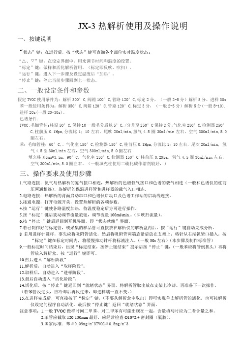
JX-3热解析使用及操作说明一、按键说明“状态”键:在运行后,按“状态”键可查询各个部位实时温度状态。
“△、▽”键:在设定界面中,用来调节时间和温度的设置。
“标定”键:做样和活化解析管用。
(标定即反吹、吹扫)。
“运行”键:进入下一步骤及设定温度后“加热”。
“停止”键:停止当前步骤回到上一状态。
二、一般设定条件和参数假定TVOC使用条件为:解析300°C,阀箱100°C,管路120°C,标定2分,(一般2-5分)解析5分。
进样30s 苯一般使用条件为:解析350°C,阀箱120°C,管路120°C,标定5分,(一般2-5分)解析5分(一般5-10). 进样20s(一般20-30s)。
色谱条件:TVOC:毛细管柱:柱温50°C,保持10一般毛分后以5°C,/分升至250°C保持2分。
气化室250°C,检测器250°C,柱前压0.1Mpa,分流比1;10左右,尾吹20ml/min,氢气4.5圈30ml/min左右,空气300ml/min,5.0圈左右。
苯:毛细管柱:60°C,。
气化室150°C,检测器150°C,柱前压0.1Mpa,分流比1;10左右,尾吹20ml/min, 氢气4.5圈30ml/min左右,空气300ml/min,5.0圈左右填充柱:Ø3mm*3.5m: 90°C, 气化室150°C,检测器150°C,柱前压0.2Mpa. 氢气4.5圈30ml/min左右,空气300ml/min,5.0圈左右。
(一般填充柱使用二硫化碳作溶剂较好,)三、操作要求及使用步骤1.气路连接:氮气与热解析的氮气接口相连,热解析的色谱载气接口和色谱的载气相连(一般和色谱仪的柱前压两通相连),热解析的保温进样管和进样器的载气入口相连。
2.电路连接:热解析的背面启动串口和色谱仪启动口及色谱工作站的启动线连接。
DiI (细胞膜红色荧光探针)说明书

DiI (细胞膜红色荧光探针)产品编号 产品名称包装 C1036DiI (细胞膜红色荧光探针)10mg产品简介:DiI 即DiIC 18(3),全称为1,1'-dioctadecyl-3,3,3',3'-tetramethylindocarbocyanine perchlorate ,是最常用的细胞膜荧光探针之一,呈现橙红色荧光。
DiI 是一种亲脂性膜染料,进入细胞膜后可以侧向扩散逐渐使整个细胞的细胞膜被染色。
DiI 在进入细胞膜之前荧光非常弱,仅当进入到细胞膜后才可以被激发出很强的荧光。
DiI 被激发后可以发出橙红色的荧光,DiI 和磷酯双层膜结合后的激发光谱和发射光谱参考下图。
其中,最大激发波长为549nm ,最大发射波长为565nm 。
DiI 的分子式为C 59H 97ClN 2O 4,分子量为933.88,CAS number 为41085-99-8。
DiI 可以溶解于无水乙醇、DMSO 和DMF ,其中在DMSO 中的溶解度大于10mg/ml 。
发现较难溶解时可以适当加热,并用超声处理以促进溶解。
DiI 被广泛用于正向或逆向的,活的或固定的神经等细胞或组织的示踪剂或长期示踪剂(long-term tracer)。
DiI 通常不会影响细胞的生存力(viability)。
被DiI 标记的神经细胞在体外培养的条件下可以存活长达4周,在体内可以长达一年。
DiI 在经过固定的神经元细胞膜上的迁移速率为0.2-0.6mm/day ,在活的神经元细胞膜上的的迁移速率为6mm/day 。
DiI 除了最简单的细胞膜荧光标记外,还可以用于检测细胞的融合和粘附,检测发育或移植过程中细胞迁移,通过FRAP(Fluorescence Recovery After Photobleaching)检测脂在细胞膜上的扩散,检测细胞毒性和标记脂蛋白等。
用于细胞膜荧光标记时,DiI 的常用浓度为1-25µM ,最常用的浓度为5-10µM 。
骨化三醇胶丸说明书
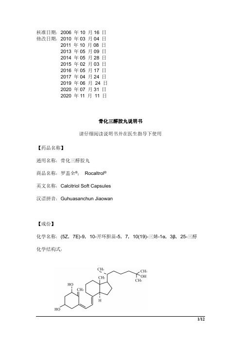
核准日期:2006年10月16日修改日期:2010年03月04日2011年10月08日2013年05月09日2014年05月28日2015年02月03日2016年05月17日2017年04月24日2019年06月24日2020年07月31日2020年11月11日骨化三醇胶丸说明书请仔细阅读说明书并在医生指导下使用【药品名称】通用名称:骨化三醇胶丸商品名称:罗盖全®;Rocaltrol®英文名称:Calcitriol Soft Capsules汉语拼音:Guhuasanchun Jiaowan【成份】化学名称:(5Z,7E)-9,10-开环胆甾-5,7,10(19)-三烯-1α,3β,25-三醇化学结构式:分子式:C27H44O3分子量:416.6【性状】本品为胶丸,内容物为无色至淡黄色或淡棕色或淡棕黄色的澄清油状液体。
【适应症】1.绝经后骨质疏松;2.慢性肾功能衰竭,尤其是接受血液透析患者之肾性骨营养不良症;3.术后甲状旁腺功能低下;4.特发性甲状旁腺功能低下;5.假性甲状旁腺功能低下;6.维生素D依赖性佝偻病;7.低血磷性维生素D抵抗型佝偻病等。
【规格】0.25 µg/粒【用法用量】应根据每个患者血钙水平谨慎制定本品的每日最佳剂量。
开始以本品治疗时,应尽可能使用最小剂量,并且不能在没有监测血钙水平的情况下增加用量。
确定了本品的最佳剂量后,应每月复查一次血钙水平(或参照下面有关个别适应症之详细说明)。
采集血钙标本时,不能使用止血带。
若血钙超过正常范围(9~11mg/100ml或2250~2750µmol/l)1mg/100ml(250µmol/l),或血肌酐大于120µmol/l,则必须减少剂量或完全中止治疗直至血钙正常。
在血钙增高期间,必须每日测定血钙及血磷水平。
血钙正常后可服用本品,但日剂量应低于前剂量0.25µg。
每日应估计钙摄入量并酌情进行调整。
红狮Crimson 2 系列G3 HMI设备说明书

G3系列HMI,图片小于实际尺寸。
web和网络支持多种不同类型的硬件。
可、驱最简洁、最灵活的软件,请访问了解我们的全线HMI产品(HMi)B操作界面 – H M I板上的以太网端口公开各类数据,允许对诊断信息或者数据记录器记录的值进行远程访问。
CompactFlash (CF 卡)帮助实现几乎无限的数据存储能力集成CF 卡插槽可以插接便宜、常见的I 类和II 类CompactFlash 卡,让您能够轻松地收集、保留以及传输数据。
如需更新已在客户处安装的设备内部的数据库,您可以通过Crimson 将该数据库的副本保存到CompactFlash 卡中,把该卡交付给客户,然后让G3从该卡中加载数据库。
USB 端口让数据传输与下载 更加快捷G3 HMI 系列有一个方便的USB 端口,可用于从PC 中快速下载配置文件,还可用于将趋势和数据记录快速上传到PC 中进行分析。
强大的处理能力G3 HMI 系列配备板载32位处理器,拥有无与伦比的计算能力。
功能齐全的Crimson 软件包含内置的“C ”编译器,可用于为复杂应用、配方处理、实时计划、数学表达式求值等等创建自定义程序。
配置与编程更迅捷Crimson 2是强大的基于图标的配置、显示、控制以及数据记录工具集合,它们专为充分利用G3 HMI 系列的架构而设计。
多数简单应用程序可通过分步过程快速设置,以配置通信协议、定义要访问的数据标记以及创建用户界面。
一整套拖放图形项不但简化了界面的创建,而且能够产生专业效果。
编程、数据记录和配置G3的web 服务器等更多高级功能既直观又容易启用。
价格最低的全功能HMI只需比许多精简版HMI 更低的价钱,您就可以增加只有G3 HMI 系列才提供的强大功能和易性。
G3系列标配有三个串行通信端口、以太网、协议转换器、USB 和CF 卡插槽。
并且,无需支付额外费用,您就可以获得功能齐全的Crimson 2软件,它包含拖放配置和数据标识功能、易用的界面工具、灵活的编程环境、强大的数据记录功能以及我们独有的虚拟面板和用于远程访问与控制的web 服务器功能。
JNASE高精度热气站说明书
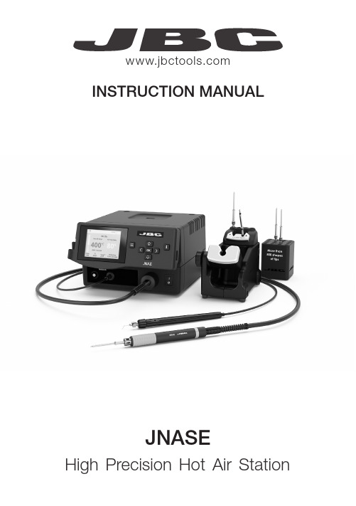
JNASEHigh Precision Hot Air StationINSTRUCTION MANUALManual ..............................1 unit Ref. 0024293Heater Hose Set ............1 unit Ref. NH-AStand ................................1 unit Ref. NA-SA JNAE Control Unit .........1 unit Ref. JNAE-A (85V -265V)Packing ListThe following items are included:Pick & Place ...................1 unit Ref. T260-A Matalic Needles andCups Set ......................... 1 unit Ref. 0026490Heating Element .............1 unit Ref. J125012Power Cord ................... 1 unit Ref. 0023715 (120V) 0023714 (230V) 0024092 (100V)Cartridge Holder .......... 1 unitRef. SCH-APedal ................................ 1 unitRef. P-4052Power SocketFuseUSB ConnectorRobot RS232 ConnectorP-405 Pedal ConnectorEquipotential Connector Auxiliar Connector Pick and Place Activation SwitchHeater Hose Set Ref. NH-AStand Ref. NA-SAUSB-A ConnectorFeatures and ConnectionsMain SwitchProcess ScreenHeating Element Ref. J125012Pick and Place Ref. T260-A3MarkCompatible CartridgesThe JNASE station works with J125 cartridges and NH-A Heater hose set.Find the model that best suits your soldering needs in ArrayØ 0.8 mmØ 1.0 mmØ 1.2 mmOK 20ºC 80%OK20ºC80%Choose the needle that best fits the component and the suction cup if needed and start as follows:OperationThis tool helps you place and remove SMDs of any size easily thanks to the suction pump.Pick & PlacePick & Place Ref. T260-ABent Needles and Cups Set*Ref. 0026490Insert the needle withthe cup for a correct suction process. Make sure the needle does not protrude from the cup.Maximum working temp: 250ºC (482ºF)*Set includes the following items (2 units of each reference):- Ref. 0026637: 20G, 60º, Ø0.60 mm/0,0236 in - Ref. 0026639: 30G, 60º, Ø0.159 mm/0.00626 in - Ref. 0026638: 25G, 60º, Ø0.26 mm/0.01023 in - Cup ref. 00940112, used with needle ref. 0026637PedalSelect menu .Then by pressing select “TOOL” and confirm with .Select “PEDAL FUNCTION” and confirm with OK button. Then choose between “HOT AIR” and “SUCTION”. Confirm again with OK button. JBC PreheatersFor rework jobs the use of preheaters is highly recommended.Applying high temperatures (350 ºC - 450 ºC / 660 ºF - 840º F) for a long time can damage both, the printed circuit and the electronic components. In addition, significant temperature differences between two points on a PCBA can also damage it due to the stress generated by expansion. Preheating is a process that minimizes thermal stress and allows the welding process to take no longer than it should.For most rework processes JBC recommends a preheat temperature between 90 and 130 ºC / 195 and 265 ºF and not exceed a heating rate of 4 ºC/s. With the use of JBC preheaters, a homoge-neous and controlled heating is achieved within the recommended parameters.7JNASE Work ScreenThe JNASE offers an intuitive user interface which provides quick access to station parameters. Default PIN: 0105Menu OptionsCurrent Air Temp.Air Temp.SelectedHeater Status IndicatorSelected Air flowStationToolsCountersResetSet the station parametersSet the tool parametersDisplay the hours worked in each cycleIt is possible tochoose the language from a list.Allows you to carry out an overall station reset restoring all the parameters to their default values.Station troubleshooting available on the product page at Troubleshooting8- Do not use the units for any purpose other than soldering or rework. Incorrect use may cause fire.- The power cord must be plugged into approved bases. Make sure that it is properly grounded before use. When unplugging it, hold the plug, not the wire.- Do not work on electrically live parts.- The tool should be placed in the stand when not in use to turn off the hot air.The soldering tip, the metal part of the tool and the stand may still be hot even when the station is turned off. Handle with care, including when adjusting the stand position.- Do not leave the appliance unattended when it is on.- Do not cover the ventilation grills. Heat can cause inflamable products to ignite.- Avoid the contact of flux with skin or eyes to prevent irritation - Be careful with the fumes produced when soldering.- Keep your workplace clean and tidy. Wear appropriate protection glasses and gloves when working to avoid personal harm.- Utmost care must be taken with liquid tin waste which can cause burns.- This appliance can be used by children over the age of eight and also persons with reduced physical, sensory or mental capabilities or lack of experience provided that they have been given adequate supervision or instruction concerning use of the appliance and understand the hazards involved. Children must not play with the appliance.- Maintenance must not be carried out by children unless supervised.SafetyIt is imperative to follow safety guidelines to prevent electricshock, injury, fire or explosion.11产品中有害物质的名称及含量有害物质含量表部件名称有害物质铅(Pb)汞(Hg)镉(Cd)六价铬(Cr(VI))多溴联苯(PBB)多溴二苯醚(PBDE)烙铁头O O O O O O手柄O O O O O O电源线O O O O O O主机O O O O O O电源插座O O O O O O保险丝O O O O O O主开关O O O O O O电位连接X O O O O O变压器O O O O O O线路板X O O O O O O 表示该有害物质在该部件所有均质材料中的含量均在GB/T 26572 规定的限量要求以下。
(推荐浙大中控)JX-300XP知识讲解
(推荐浙大中控)JX-300XP知识讲解JX-300XP一、判断题1.一个XP202机柜最多配置7只机笼,其中1只电源机笼、6只I/O机笼。
(×)2.主控制卡和数据转发卡均可进行冗余设置,冗余设置方法为:插上短路块代表冗余,取下短路块代表单卡工作。
(×)3.在组态设置时,主控制卡地址只能从1开始,且只能为奇数。
(×)4.在组态设置时,数据转发卡的地址只能从2开始。
(×)5.在机柜XP202的供电过程中,一只电源能同时给1、2#或3、4#机笼供电。
(√)6.模拟量信号输出卡XP322可输出0~5V和1~5V的标准电压信号。
(×)7.主控制卡XP243存放目标代码(SCconTrol)的容量为348K。
(√)8.XP243主控制卡与XP233数据转发卡之间是通过SCnetII网络相联接的。
(×)9.JX-300XP DCS 除了电源、主控制卡、数据转发卡和网络外,其余I/O卡可任意冗余。
(×)10.JX-300XP DCS 支持带电插拔卡件。
(√)11.JX-300XP DCS在不开控制站机柜门的情况下,可以从监控软件画面上了解到控制站机柜中卡件的详细布置图和各I/O卡件的工作情况及发生故障的情况。
(√)12.JX-300XP系统中,SCNET-II网络可以采用星型或者总线型的网络拓扑方式。
(√)13.JX-300XP中,每个I/O机笼与其他机笼通过1条SBUS电缆连接,因此SBUS网络实际上是不冗余的。
(×)14.SBUS-S2总线上的最大节点数目为6。
(×)15.SBUS-S1是不冗余的。
(√)16.主控卡和数据转发卡之间的网络是SBUS-S1。
(×)17.数据转发卡和机笼内I/O卡件之间的网络是SBUS-S2。
(×)18.连接远程机笼时,如果使用XP433M,则可以不配置光电转换盒。
(√)19.光纤接续盒需要进行光纤熔接。
3 x 2 3 GN 电子湿热转热炉产品说明书

4 Spare parts list
Lista ricambi
Brand/Marchio: Factory code:
All 9PDX
From sr. Nr/ Da Ser. Nr.: ***
From status level / Da scatto: **
Page: 1
Ed. 2015 09 Doc. Nr.: 875401M00
60 0282217501 057534 Guarnizione resistenza
Gasket, heating element
61 0682800000 054842 Motoventilatore forno
Fan motor, oven
62 0446578602 057937 Termostato
5 0855889602 054844 Guide Dx
6 0514846900 054868 Supporto anteriore guide
7 0805833900 054855 Cerniera superiore porta
8 0875854503 054849 Controporta
9 0543805500 054850 Guarnizione per vetro
Page: 3
Ed. 2015 09 Doc. Nr.: 875401M00
3 x 2/3 GN ELECTRIC HUMIDIFIED CONVECTION OVEN FORNO CONVEZIONE ELETTRICO UMIDIFICATO 3 x 2/3 GN
Pos
Factory Code
Ref. Group Page Notes
a
CLASSIC III 线性电焊机操作手册说明书
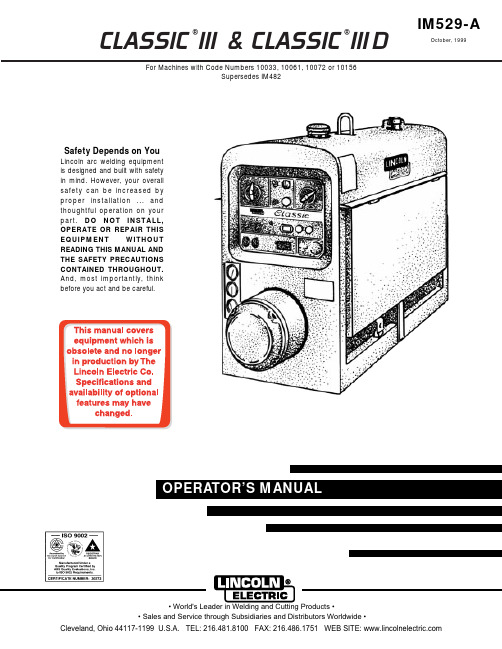
CLASSIC ®III & CLASSIC ®III DFor Machines with Code Numbers 10033, 10061, 10072 or 10156Supersedes IM482IM529-AOctober, 1999Safety Depends on YouLincoln arc welding equipment is designed and built with safety in mind. However, your overall safety can be increased by proper installation ... and thoughtful operation on your part.DO NOT INSTALL,OPERATE OR REPAIR THIS EQUIPMENT WITHOUT READING THIS MANUAL AND THE SAFETY PRECAUTIONS CONTAINED THROUGHOUT.And, most importantly, thinkbefore you act and be careful.Mar ‘95Mar. ‘93for selecting a QUALITY product by Lincoln Electric. We want you to take pride in operating this Lincoln Electric C ompany product ••• as much pride as we have in bringing this product to you!Read this Operators Manual completely before attempting to use this equipment. Save this manual and keep it handy for quick reference. Pay particular attention to the safety instructions we have provided for your protection.The level of seriousness to be applied to each is explained below:vvviTECHNICAL SPECIFICATIONS – CLASSIC III AND IIID Machine*Based on a 10 min. period.@Meets Canadian StandardsProduct Name Description Horsepower OperatingSpeedsDisplacement Ignition CapacitiesClassic III Classic III D4 Cylinder4 CycleWater-CooledGasoline EngineCast Iron Cylinder,Block/Crankcase4 Cylinder4 CycleWater-CooledDiesel EngineCast Iron Cylinder,Block/Crankcase45 HP@ 1700 RPM38.9 HP@ 1700 RPMFull Load:1725 RPMHigh Idle:1800 RPMLow Idle:1350 RPM164.7 Cu In(2.7 ltrs)Distributor TypeElectronicDieselFuel:15 Gals (57 Ltrs)Lubricating Oil:7.0 Qts (6.7 Ltrs)Coolant:9.3 Qts (8.8 Ltrs)EngineB AWire Feed Module (K623-1) - Provides constant voltage (C V) output with improved arc stability for Innershield welding. Excellent for MIG welding. Recommended wire feeders are the LN-7, LN-23P and LN-25. (Factory installed on the K1428-3 and K1433-2).NameplatesWhenever routine maintenance is performed on this machine - or at least yearly - inspect all nameplates and labels for legibility. Replace those which are no longer clear. Refer to the parts list for the replace-ment item number.I = Inspect C = Clean R = Replace NOTES:(1)Consult Engine Operators Manual for oil recommendations.(2)Or equivalent.(3)First inspection after 50 hours; every 500 thereafter.(4)Gasoline engine only.(5)Diesel engine only. (Welder Code Numbers 10061 and below)(6)Diesel engine only. (Welder Code Numbers above 10061)(7)Consult Engine Operators Manual for additional maintenance schedule information.5-6-94C S20919-1TROUBLESHOOTINGHave qualified personnel do the troubleshooting work. Turn the engine off before working inside the machine. In some cases, it may be neces-sary to remove safety guards to perform required maintenance. Remove guards only when necessary and replace them when the maintenance requiring their removal is com-plete. Always use the greatest care when work-ing near moving parts.Do not put your hands near the engine cooling blower fan. If a problem cannot be corrected by following the instructions, take the machine to the nearest Lincoln Field Service Shop.------------------------------------------------------------ELECTRIC SHOCK can kill.•Do not touch electrically live parts or electrode with skin or wet clothing.•Insulate yourself from work and ground• Always wear dry insulating gloves.EXHAUST can kill.Use in open, well ventilated areas or vent exhaust outside.------------------------------------------------------------------------MOVING PARTS can injure.•Do not operate with doors open or guards off.• Stop engine before servicing.• Keep away from moving parts.------------------------------------------------------------------------See additional warning information at the front of this operator’s manual------------------------------------------------------------(1)FLASHING THE FIELDS:1.Stop the engine welder and remove the cover from the exciter.2.Turn the “Fine Adjustment Control” (rheostat) to “100” on the dial.ing a 12 volt automotive battery, connect it’s negative terminal to the negative brushholder. Thenegative brushholder is the one nearest to the rotor lamination. See the wiring diagram. With theengine NOT running, touch the positive battery terminal to the positive brushholder. Remove thebattery from the circuit.4.Replace the exciter cover. Start the welder and the generator voltage should build up.ENGINE TROUBLESHOOTING - (TM27 Gasoline Engine Only)**See engine manual.L 9260C L A S S I C I I ID W I R I N G D I A G R A ME : T h i s d i a g r a m i s f o r r e f e r e n c e o n l y . I t m a y n o t b e a c c u r a t e f o r a l l m a c h i n e s c o v e r e d b y t h i s m a n u a l . T h e s p e c i f i c d i a g r a m f o r a p a r t i c u l a r c o d e i s p a s t e d i n s i d e a c h i n e o n o n e o f t h e e n c l o s u r e p a n e l s . I f t h e d i a g r a m i s i l l e g i b l e , w r i t e t o t h e S e r v i c e D e p a r t m e n t f o r a r e p l a c e m e n t . G i v e t h e e q u i p m e n t c o d e n u m b e r ..Now Available...12th EditionThe Procedure Handbook of Arc WeldingWith over 500,000 copies of previous editions published since 1933, the Procedure Handbook is considered by many to be the “Bible” of the arc welding industry.This printing will go fast so don’t delay. Place your order now using the coupon below.The hardbound book contains over 750 pages of welding information, techniques and procedures. Much of this material has never been included in any other book.A must for all welders, supervisors, engineers and designers. Many welding instructors will want to use the book as a reference for all students by taking advantage of the low quantity discount prices which include shipping by 4th class parcel post.$15.00postage paid U.S.A. MainlandHow To Read Shop DrawingsThe book contains the latest information and application data on the American Welding Society Standard Welding Symbols. Detailed discussion tells how engineers and draftsmen use the “short-cut” language of symbols to pass on assembly and welding information to shop personnel.Practical exercises and examples develop the reader’s ability to visualize mechanically drawn objects as they will appear in their assembled form.187 pages with more than 100 illustrations. Size 8-1/2” x 11”Durable, cloth-covered board binding.$4.50postage paid U.S.A. MainlandNew Lessons in Arc WeldingLessons, simply written, cover manipulatory techniques;machine and electrode characteristics; related subjects,such as distortion; and supplemental information on arc welding applications, speeds and costs. Practice materials,exercises, questions and answers are suggested for each lesson.528 pages, well illustrated, 6” x 9” size, bound in simulated,gold embossed leather.$5.00postage paid U.S.A. MainlandNeed Welding Training?The Lincoln Electric C ompany operates the oldest and most respected Arc Welding School in the United States at its corporate headquarters in C leveland, Ohio. Over 100,000stu-dents have graduated. Tuition is low and the training is “hands on”For details write:Lincoln Welding School 22801 St. Clair Ave.Cleveland, Ohio 44117-1199.and ask for bulletin ED-80 or call 216-383-2259 and ask for the Welding School Registrar.Lincoln Welding SchoolBASIC COURSE $700.005 weeks of fundamentalsThere is a 10%discount on all orders of $50.00 or more for shipment at one time to one location.Orders of $50 or less before discount or orders outside of North America must be prepaid with charge, check or money order in U.S. Funds Only.Prices include shipment by 4th Class Book Rate for U.S.A. Mainland Only.Please allow up to 4 weeks for delivery.UPS Shipping for North America Only.All prepaid orders that request UPS shipment please add:$5.00For order value up to $49.99$10.00For order value between $50.00 & $99.99$15.00For order value between $100.00 & $149.00For North America invoiced orders over $50.00 & credit card orders, if UPS is requested, it will be invoiced or charged to you at cost.Outside U.S.A. Mainland order must be prepaid in U.S. Funds. Please add $2.00 per book for surface mail or $15.00 per book for air parcel post shipment.METHOD OF PAYMENT:(Sorry, No C.O.D. Orders)CHECK ONE:Name:_______________________________________________Please Invoice (only if order is over $50.00)Address:_______________________________________________Check or Money Order Enclosed, U.S. Funds only _______________________________________________Credit Card - Telephone:_______________________________________________Signature as it appears on Charge Card:Account No.Exp Date|_|_||_|_|______________________Month YearUSE THIS FORM TO ORDER:Order from:BOOK DIVISION, The Lincoln Electric Company, 22801 St. Clair Avenue, Cleveland, Ohio 44117-1199BOOKS OR FREE INFORMATIVE CATALOGS Telephone: 216-383-2211 or, for fastest service, FAX this completed form to: 216-361-5901.Lincoln Welding School Titles:Price Code QuantityCost(ED-80)New Lessons in Arc Welding $5.00L Seminar Information Procedure Handbook “Twelfth Edition”$15.00PH (ED-45)How to Read Shop Drawings $4.50H Educational Video Information Incentive Management $5.00IM (ED-93) A New Approach to Industrial Economics $5.00NA James F. Lincoln Arc Welding The American Century of John C. Lincoln $5.00AC Foundation Book Information Welding Preheat Calculator $3.00WC-8(JFLF-515)Pipe Welding Charts $4.50ED-89SUB TOTALAdditional Shipping Costs if anyTOTAL COSTJapaneseChineseKoreanArabicREAD AND UNDERSTAND THE MANUFACTURER’S INSTRUCTION FOR THIS EQUIPMENT AND THE CONSUMABLES TO BE USED AND FOLLOW YOUR EMPLOYER’S SAFETY PRACTICES.SE RECOMIENDA LEER Y ENTENDER LAS INSTRUCCIONES DEL FABRICANTE PARA EL USO DE ESTE EQUIPO Y LOS CONSUMIBLES QUE VA A UTILIZAR, SIGA LAS MEDIDAS DE SEGURIDAD DE SU SUPERVISOR.LISEZ ET COMPRENEZ LES INSTRUCTIONS DU FABRICANT EN CE QUI REGARDE CET EQUIPMENT ET LES PRODUITS A ETRE EMPLOYES ET SUIVEZ LES PROCEDURES DE SECURITE DE VOTRE EMPLOYEUR.LESEN SIE UND BEFOLGEN SIE DIE BETRIEBSANLEITUNG DER ANLAGE UND DEN ELEKTRODENEINSATZ DES HER-STELLERS. DIE UNFALLVERHÜTUNGSVORSCHRIFTEN DES ARBEITGEBERS SIND EBENFALLS ZU BEACHTEN.JapaneseChineseKoreanArabicLEIA E COMPREENDA AS INSTRUÇÕES DO FABRICANTE PARA ESTE EQUIPAMENTO E AS PARTES DE USO, E SIGA AS PRÁTICAS DE SEGURANÇA DO EMPREGADOR.• Sales and Service through Subsidiaries and Distributors Worldwide •Cleveland, Ohio 44117-1199 U.S.A. TEL: 216.481.8100 FAX: 216.486.1751 WEB SITE: 。
WDJD-3多功能数字直流激电仪说明书
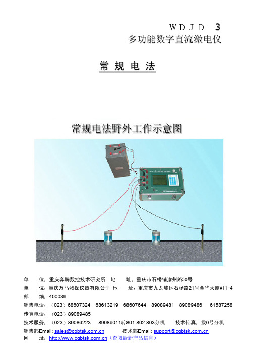
二 仪器主要技术指标 1. 接收部分 电压通道 测量精度 Vp 10mV时 Vp 10mV时 输入阻抗 50 视极化率测量精度 1 补偿范围 电流通道 5 测量精度 Ip 10mA时
0.5% 1% 1个字
1个字 1个字
0.5%
1个字
2
Ip 10mA时 1% 1个字 对50Hz工频干扰 共模干扰与差模干扰 压制优于80dB 2. 发射部分 最大发射功率 45 9 最大供电电压 5 最大供电电流 供电脉冲宽度 秒 占空比为 3. 其它 工作温度 -10 +50 95 RH +60 储存温度 -20 仪器电源 号电池 或同样规格的镍镉电池 节 55 整机电流 重 量 体积 310mm 210mm 210mm 仪器工作原理 如图3-1所示 仪器由CPU单元 发送和接收三部分组成 电压信号从 输入 经过阻抗变换滤波后与 补偿信号相减 再经程 控放大送到 进行转换 电流信号则由标准电阻采样后 经隔放 滤波 程控放大送 进行转换 由单片机从 取出电压与电流信号的转换结 果 送显示器显示 仪器采用人机对话方式来完成各种测量功能 三
3 多功能数字直流激电仪
常 规 电 法
使用说明书
单 单 邮
位 编
重庆奔腾数控技术研究所 400039 023 68607324 023 89089485 023 89086223
地
址
重庆市石桥铺渝州路50号
位 重庆万马物探仪器有限公司 地 68613219
址 重庆市九龙坡区石杨路21号金华大厦A11-4 68607644 89089481 89089486 61587258
销售电话 传真电话 技术服务
89086011转801 802 803分机
技术传真 拨0号分机
山立组合式冷干机界面使用说明书

山立组合式冷干机界面使用说明书(总6页)--本页仅作为文档封面,使用时请直接删除即可----内页可以根据需求调整合适字体及大小--SLAD-160ZW-M仪表板及显示器操作说明一.仪表板说明1-1#冷媒高压表:指示冷媒的冷凝压力值。
2-1#冷媒低压表:指示蒸发器内冷媒的饱和压力值。
3-2#冷媒高压表:指示冷媒的冷凝压力值。
4-2#冷媒低压表:指示蒸发器内冷媒的饱和压力值。
5-空气压力表:指示压缩空气在干燥机进口处的压力值。
6-显示器:显示设备状态,设置运行参数。
7-温度控制器:加热器超温保护用用温度控制器,显示加热器的温度值,设置值为180℃。
8-1#加热器加热指示灯:此灯亮表示设备1#加热器正在加热运行。
9-2#加热器加热指示灯:此灯亮表示设备1#加热器正在加热运行。
10-3#加热器加热指示灯:此灯亮表示设备1#加热器正在加热运行。
11-A塔吸附指示灯:该灯亮表示A塔在吸附。
12-B塔一级再生指示灯:该灯亮表示B塔一级再生阀打开。
13-B塔二级再生指示灯:该灯亮表示B塔二级再生阀打开。
14-B塔吸附指示灯:该灯亮表示B塔在吸附。
15-A塔一级再生指示灯:该灯亮表示A塔一级再生阀打开。
16-A塔二级再生指示灯:该灯亮表示A塔二级再生阀打开。
17-远程/就地转换开关:用于远程/就地控制之间的转换。
18-启动按钮:远程/就地转换开关在就地档,可开启设备。
19-停止按钮:远程/就地转换开关在就地档,可停止设备。
或冷干机发生故障后,排除外部故障。
按停止按钮复位PLC内部程序。
20--电源指示灯:该灯亮表示通电21-1#机运行指示灯:此灯亮表示设备冷干机1#制冷压缩机正在运行。
22-2#机运行指示灯:此灯亮表示设备冷干机2#制冷压缩机正在运行。
此压缩机在负荷低的情况下停止工作,在负荷高的情况下恢复工作。
23-待启动指示灯:表示按停止按钮正常停机后,过五分钟后此灯亮,此时可以按启动按钮可再次启动设备。
24-故障指示灯:此灯亮表示出现故障,设备会停机,需检查排除故障. 故障排除后按停止按钮复位控制器(PLC)内部程序,按启动按钮才能启动设备。
Schneider Electric TeSys GV3 产品数据手册说明书
T h e i n f o r m a t i o n p r o v i d e d i n t h i s d o c u m e n t a t i o n c o n t a i n s g e n e r a l d e s c r i p t i o n s a n d /o r t e c h n i c a l c h a r a c t e r i s t i c s o f t h e p e r f o r m a n c e o f t h e p r o d u c t s c o n t a i n e d h e r e i n .T h i s d o c u m e n t a t i o n i s n o t i n t e n d e d a s a s u b s t i t u t e f o r a n d i s n o t t o b e u s e d f o r d e t e r m i n i n g s u i t a b i l i t y o r r e l i a b i l i t y o f t h e s e p r o d u c t s f o r s p e c i f i c u s e r a p p l i c a t i o n s .I t i s t h e d u t y o f a n y s u c h u s e r o r i n t e g r a t o r t o p e r f o r m t h e a p p r o p r i a t e a n d c o m p l e t e r i s k a n a l y s i s , e v a l u a t i o n a n d t e s t i n g o f t h e p r o d u c t s w i t h r e s p e c t t o t h e r e l e v a n t s p e c i f i c a p p l i c a t i o n o r u s e t h e r e o f .N e i t h e r S c h n e i d e r E l e c t r i c I n d u s t r i e s S A S n o r a n y o f i t s a f f i l i a t e s o r s u b s i d i a r i e s s h a l l b e r e s p o n s i b l e o r l i a b l e f o r m i s u s e o f t h e i n f o r m a t i o n c o n t a i n e d h e r e i n .Product data sheetCharacteristicsGV3P18TeSys GV3 Manual Starter and Protector,thermal magnetic circuit protector, rotary knob,12…18 A, EverLink BTR connectorsProduct availability: Stock - Normally stocked in distribution facilityMainRange TeSys Product name TeSys GV3Device short name GV3P Device application MotorTrip unit technologyThermal-magneticComplementaryPoles description 3P Network type ACUtilisation category AC-3 IEC 60947-4-1Category A IEC 60947-2Network frequency 50/60 Hz IEC 60947-4-1Fixing mode 35 mm symmetrical DIN rail clipped Panel screwed with 3 x M4 screws)Operating position Any positionMotor power kW7.5 KW 400/415 V AC 50/60 Hz 9 KW 500 V AC 50/60 Hz 15 kW 690 V AC 50/60 HzBreaking capacity100 KA Icu 230/240 V AC 50/60 Hz IEC 60947-2100 KA Icu 400/415 V AC 50/60 Hz IEC 60947-250 KA Icu 440 V AC 50/60 Hz IEC 60947-26 KA Icu 690 V AC 50/60 Hz IEC 60947-212 kA Icu 500 V AC 50/60 Hz IEC 60947-2[Ics] rated service short-circuit breaking capacity100 % 230/240 V AC 50/60 Hz IEC 60947-2100 % 440 V AC 50/60 Hz IEC 60947-2100 % 400/415 V AC 50/60 Hz IEC 60947-250 % 500 V AC 50/60 Hz IEC 60947-250 % 690 V AC 50/60 Hz IEC 60947-2Control type Rotary knob Line Rated Current18 A Thermal protection adjustment range 12…18 A Magnetic tripping current 252 A[Ue] rated operational voltage 690 V AC 50/60 Hz IEC 60947-2[Ui] rated insulation voltage690 V AC 50/60 Hz IEC 60947-2[Ith] conventional free air thermal current 18 A IEC 60947-4-1[Uimp] rated impulse withstand voltage 6 kV IEC 60947-2Power dissipation per pole 8 WMechanical durability 50000 cyclesElectrical durability 50000 cycles AC-3 440 V In Maximum operating rate 25 cyc/hRated dutyContinuous IEC 60947-4-1Connections - terminals EverLink BTR screw connectors 2 0.00…0.04 in² (1…25 mm²) solidEverLink BTR screw connectors 2 0.00…0.04 in² (1…25 mm²) flexible without ca-ble endEverLink BTR screw connectors 2 0.00…0.04 in² (1…25 mm²) flexible with cableendTightening torque44.25 Lbf.In (5 N.m) EverLink BTR screw connectors 0.04 in² (25 mm²)70.81 lbf.in (8 N.m) EverLink BTR screw connectors 0.05 in² (35 mm²) Suitability for isolation Yes IEC 60947-1Phase failure sensitivity Yes IEC 60947-4-1Height 5.20 in (132 mm)Width 2.17 in (55 mm)Depth 5.35 in (136 mm)Net weight 2.12 lb(US) (0.96 kg)EnvironmentStandards EN/IEC 60947-2EN/IEC 60947-4-1CSA C22.2 No 60947-4-1UL 60947-4-1Product certifications IECEE CB SchemeULCSACCCEACATEXBVLROS (Lloyds register of shipping)DNV-GLABSProtective treatment THIP degree of protection IP20 IEC 60529IK degree of protection IK09Ambient air temperature for operation-4…140 °F (-20…60 °C)Ambient air temperature for storage-40…176 °F (-40…80 °C)Fire resistance1760 °F (960 °C) IEC 60695-2-1Operating altitude9842.52 ft (3000 m)Ordering and shipping detailsCategory22366 - MAN STR PROTECTORS-GV1/GV3Discount Schedule I11GTIN00785901492252Package weight(Lbs) 1.00 kg (2.2 lb(US))Returnability YesCountry of origin FROffer SustainabilitySustainable offer status Green Premium productREACh Regulation REACh DeclarationEU RoHS Directive Compliant EU RoHS DeclarationMercury free YesRoHS exemption information YesChina RoHS Regulation China RoHS DeclarationEnvironmental Disclosure Product Environmental ProfileCircularity Profile No need of specific recycling operations End of Life InformationWEEE The product must be disposed on European Union markets following specificwaste collection and never end up in rubbish bins.Contractual warrantyWarranty18 monthsProduct data sheetPerformance CurvesGV3P18Thermal-Magnetic Tripping CurvesAverage Operating Times at 20 °C Related to Multiples of the Setting Current1a 3 poles from cold state (Ir minimum): GV3P 1b 3 poles from cold state (Ir maximum): GV3P 2a 3 poles from hot state (Ir minimum): GV3P 2b 3 poles from hot state (Ir maximum): GV3PCurrent Limitation on Short-Circuit (3-Phase 400/415 V)Dynamic StressI peak = f (prospective Isc) at 1.05 Ue = 435 V1Maximum peak current270-80 A (GV3P80), 62-73 A (GV3P73)348-65 A (GV3P65)437-50 A (GV3P50)530-40 A (GV3P40)623-32 A (GV3P32)717-25 A (GV3P25)812-18 A (GV3P18)99-13 A (GV3P13)Maximum Thermal Limit on Short-Circuit Thermal Limit in kA2s in the Magnetic Operating Zone Sum of I2dt = f (prospective Isc) at 1.05 Ue = 435 V170-80 (GV3P80) - 62-73 (GV3P73) 248-65 A (GV3P65)337-50 A (GV3P50)430-40 A (GV3P40)523-32 A (GV3P32)617-25 A (GV3P25)712-18 A (GV3P18)89-13 A (GV3P13)Dimensions DrawingsGVl3L, GV3PDimensions(1)Blocks GVAN ●●, GVAD ●● and GVAM11.(2)Blocks GV3AU ●● and GV3AS ●●.X1 = Electrical clearance (ISC max) 40 mm for Ue ≤ 500 V, 50 mm for Ue ≤ 690 VNOTE: Leave a space of 9 mm between 2 circuit breakers: either an empty space or side-mounting add-on contact blocks. Side by side mounting is possible up to 40 °C.Mounting on Rail AM1 DE200 or AM1 ED201Panel Mounting, using M4 ScrewsMounting on Pre-Slotted Plate AM1 PAConnections and Schema GV3P••。
JX-3热解析说明书2011-2-25 水印

电话:(010)68033419,68033420,68033421
4
BCHP
受控文件
5
十、仪器的故障原因与排除方法:
故障现象 仪器不能启动 进样出峰小 重复性差
进样不出峰 或响应值小
进样杂峰多
故障原因
1、电路没有接通 2、保险管坏 气路连接处漏气 1、气路系统漏气 3、样品配置不准 3、加热时间不一致 1、进样针头堵
(13)连接。 c) 打开氮气,调整稳压阀(9)将压力调节至与色谱柱前压相同。接
通电源,打开电源开关(12),设置仪器的各项参数,待温度稳
2
定(出厂默认300℃)后可以进行进样操作。(具体操作方法 见附录)。 d) 打开标定及采样开关,调节流量控制(5)。 e) 如有问题请与我所技术服务部联系。
BCHP 电话:010-68033419转30、36
BCHP 化。
气路连接示意图
JX-3按键说明图
运行键:进入下一步骤
受控文件 停止键:停止当前步骤并回到上一状态
设置键:在自检结束后按设置键进入设 定界面
状态键:在运行之后按状态键可查询各 个部位实时温度状况
标定键:做标样及活化解析管时使用 上下键:在设定界面中用来调节时间和
温度的设置
8
连接方法一:(此方法是用热解析仪控制气相色谱的载气,不用对 色谱的气路进行改动)
BCHP
BCHP JX-3型热解析仪 使 用 说
受控文件 明 书 北京中惠普分析技术研究所
在使用仪器前,请您认真阅读此使用说明。 敬告: 1、加热盒温度较高请避免直接接触加热体 2、请使用符合标准的解吸管;为了达到最佳的分析效果建议
BCHP 使用不锈钢Tenax解析管
3、载气(氮气)请使用钢瓶气 4、有EPC或其他电子流量稳定电路的气相色谱仪请参考附录
关于申报资料中参考文献统一格式的通知——02.25

关于申报资料中参考文献统一格式的通知为提高申报资料质量,保证各项目研究人员撰写资料时参考文献的统一性,特统一发布各种类型参考文献的标准格式如下,请各相关人员知悉:1、期刊论文格式:[序号]主要责任者.文献题名[J].刊名,年,卷(期):起止页码.范例:[1]黄战军,潘莹等.依折麦布联合阿托伐他汀的调脂疗效和安全性的临床研究[J].齐齐哈尔医学院学报,2011,32(20):3270-3272.2、FDA下载的资料(包括FDA下载的说明书、综述资料)格式:[序号]FDA.资料名称:页码(下载地址链接)范例:[2]FDA.Pharmacology Review(s):13-14(/drugsatfda_docs/nda/2009/022348_caldolor_toc.cfm)3、报纸文章格式:[序号]主要责任者.文献题名[N].报纸名,出版日期(版次).范例:[3]谢希德.创造学习的新思路[N].人民日报,1998-12-25(10).4、药品说明书格式:[序号]药品通用名(商品名)药品使用说明书.批准文号:xxxxxxxx,生产企业.范例:[4]依折麦布片(益适纯)药品使用说明书.批准文号:H20110326,先灵葆雅.5、非书籍中引用的药品标准格式:[序号]药品通用名称,标准来源,标准号:XXXXXXX(若有)/或起止页码(若有,可附下载地址)范例1:[1]依折麦布片,国家食品药品监督管理局进口药品注册标准,标准号:JX20070201.范例2:[2]Ibuprofen,欧洲药典EP7.0:2225-2227(/Pharmacopoeia/EP7/DATA/0721E.PDF)6、出版书籍格式:[序号]主要责任者.文献题名[M].出版地:出版者,出版年份.起止页码(可选)范例:[6]国家药典委员会.中华人民共和国药典2010年版二部[M].北京:中国医药科技出版社.附录75-767、专利格式:[序号]专利申请者或所有者.专利题名:专利国别,专利号[P].公告日期或公开日期.范例:[7]姜锡洲.一种温热外敷药制备方案:中国,CN88105607.3[P].1989-07-26.8、药监系统官方网站发布的管理规范、技术指南、指导原则格式:发布机构英文缩写(国内/国外指导原则):《原则题名》,发布年份.官网链接范例1:[1]SFDA/CDE(国内指导原则):《化学药物临床药代动力学研究技术指导原则》,2007.范例2:[2]SFDA:《化学和生物制品临床试验的生物统计学技术指导原则》,2008.。
JFD-3局部放电检测分析系统使用说明书

使用指南
目录
第一章 第二章 第三章 第四章 第五章 第六章 第七章
局放理论概述。 局放测试的试验系统接线。 数字式局部放电检测分析系统的工作原理。 数字式局部放电检测分析系统使用操做说明。 抗干扰措施和局部放电图谱简介。 局部放电测试当中应该注意的问题 产品保养及售后服务
3
使用指南
第一章 局放理论概述
在开始我们的实验以前,我们首先应该对局部放电有个初步的了 解,为什么要测量局部放电?局部放电有什么危害?怎样准确测量局 部放电?有了上述理论基础可以帮助我们理解测量过程中的正确操 作。
一、局部放电的定义及产生原因
在电场作用下,绝缘系统中只有部分区域发生放电,但尚未击 穿,(即在施加电压的导体之间没有击穿)。这种现象称之为局部放电。 局部放电可能发生在导体边上,也可能发生在绝缘体的表面上和内 部,发生在表面的称为表面局部放电。发生在内部的称为内部局部放 电。而对于被气体包围的导体附近发生的局部放电,称之为电晕。由 此 总结一下局部放电的定义,指部分的桥接导体间绝缘的一种电气 放电,局部放电产生原因主要有以下几种: 1、 电场不均匀。 2、 电介质不均匀。 3、 制造过程的气泡或杂质。最经常发生放电的原因是绝缘体内部
Uc(t)几乎瞬间地从 Vc 降到 Vr,Vr 是残余电压;而气泡上电压 Uc‘(t)
将随 U(t)的增大而继续由 Vr 升高到 Vc 时,气泡再—次击穿,发生
又—次局部放电,但此时相应的外施电压比 Us 小,为(Us-Ur),这是
因为气泡上有残余电压 Vr 的内电场作用的结果。Vr 是与气泡残余电
库(pc)表示,通常以稳定出现的最大视在放电电荷作为该试
品的放电量。
2 放电重复率——在测量时间内每秒中出现的放电次数的平均
JXG系列说明书曲阜嘉信变频器

JXG系列说明书曲阜嘉信变频器12020年4月19日第一章产品简介1.1简介我公司生产的JX系列高性能变频调速器选用了最新的功率模块和单片机控制,采用先进的电压空间矢量控制方式,可实现自动转矩提升、自动转差补偿、自动电压调整、自动节能运行等多种智能化控制,具有精度高、噪音低、转矩大、性能可靠等特点,适用于三相异步电动机的无级调速,与本公司生产的YVP系列变频调速三相异步电动机配套使用效果更佳,可广泛应用于塑料、造纸、化工、食品、制药、印染、供水等行业,是交流调速电机节能改造和设备更新换代的理想产品。
本产品具有完善的调速及保护功能:●宽广的频率调节范围输出频率可在0.5~400Hz之间任意调节;- 1 -2020年4月19日●较高的调速精度数字设定:最高频率的±0.01%;模拟设定:最高频率的±0.3% ;●完善的保护功能对于过流、过压、过载、欠压、过热、短路、缺相等故障可实现快速而有效的保护,确保变频器的安全。
加减速时间设置不当时可失速保护,避免变频器在急剧加速或减速时发生故障。
1.2技术指标- 2 -2020年4月19日- 3 - 2020年4月19日1.3开箱、存放、搬运1.3.1开箱JX-G系列变频器出厂之前已经过严格的检验,但在运输途中可能受损,因此开箱后,首先检查以下各项是否齐全,规格型号与定单是否相符:●完整的JX-G变频器;●产品使用说明书;●装箱单、质保卡;●如有疑问或产品出现损坏等,请与经销商或本公司联系。
1.3.2存放本产品存放时应注意以下事项:●置于无尘和干燥通风的场所;●环境温度在-20℃~+60℃范围内;●远离腐蚀性气体、液体;- 4 -2020年4月19日相对湿度小于90%,且无凝露现象。
变频器长时间存放会导致电解电容老化,如需长期存放时,必须保证至少半年内通电一次,通电应在4~6小时以上,通电时输入电压应用调压器缓缓升高至额定电压值。
1.3.3搬运本产品在搬运过程中,应避免强烈振动、摔跌和磕碰;开箱搬运时,切勿丢弃或遗失附件以及说明书等。
Nieco 电子炉 JF64-3 产品说明书

F O R Y O U R S A F E T Y :Do not store or use gasoline or other flammable vapors or liquids in the vicinity of this or any otherappliance.A P P ROVA L S :IMPORTANT: RETAIN THIS MANUAL IN A SAFE PLACE FOR FUTURE REFERENCEBroiler area must be kept free of combustible materials, and the flow of combustion and ventilation air must not be obstructed. Operating personnel must not perform any maintenance or repairfunctions. Contact your Nieco Authorized Dealer.Table of ConTenTsa.General Information . . . . . . . . . . . . . . . . . . . . . . . . . . . . . . . . . . . . . . . . . . .3A.1Description . . . . . . . . . . . . . . . . . . . . . . . . . . . . . . . . . . . . . . . . . . . . .3A.2 Warranty Information . . . . . . . . . . . . . . . . . . . . . . . . . . . . . . . . . . . . .3A.3 Service/Technical Assistance . . . . . . . . . . . . . . . . . . . . . . . . . . . . . . .4A.4 Safety Information . . . . . . . . . . . . . . . . . . . . . . . . . . . . . . . . . . . . . . .4 b.Machine Installation . . . . . . . . . . . . . . . . . . . . . . . . . . . . . . . . . . . . . . . . . . .6B.1 Pre-Installation . . . . . . . . . . . . . . . . . . . . . . . . . . . . . . . . . . . . . . . . . .6B.2 Mounting . . . . . . . . . . . . . . . . . . . . . . . . . . . . . . . . . . . . . . . . . . . . . .6B.3 Leveling . . . . . . . . . . . . . . . . . . . . . . . . . . . . . . . . . . . . . . . . . . . . . . .6B.4 Hood Requirements . . . . . . . . . . . . . . . . . . . . . . . . . . . . . . . . . . . . . .6B.5 Clearance . . . . . . . . . . . . . . . . . . . . . . . . . . . . . . . . . . . . . . . . . . . . . .6B.6 Gas Connection . . . . . . . . . . . . . . . . . . . . . . . . . . . . . . . . . . . . . . . . .7B.7 Flexible Gas Line Installation . . . . . . . . . . . . . . . . . . . . . . . . . . . . . . .7B.8 Restraining Device . . . . . . . . . . . . . . . . . . . . . . . . . . . . . . . . . . . . . . .8B.9 Electrical Connection . . . . . . . . . . . . . . . . . . . . . . . . . . . . . . . . . . . . .8B.10Pre-Operation Check . . . . . . . . . . . . . . . . . . . . . . . . . . . . . . . . . . . . .8C. operation . . . . . . . . . . . . . . . . . . . . . . . . . . . . . . . . . . . . . . . . . . . . . . . . . . . .9C.1Controls and Indicators . . . . . . . . . . . . . . . . . . . . . . . . . . . . . . . . . . .9C.2 Step-by-Step Lighting Procedure . . . . . . . . . . . . . . . . . . . . . . . . . . .10C.3 Shutdown Procedure . . . . . . . . . . . . . . . . . . . . . . . . . . . . . . . . . . . .11C.4 Control Operation . . . . . . . . . . . . . . . . . . . . . . . . . . . . . . . . . . . . . . .12D.assembly/Disassembly and Cleaning . . . . . . . . . . . . . . . . . . . . . . . . . . . .13e.Troubleshooting Guide . . . . . . . . . . . . . . . . . . . . . . . . . . . . . . . . . . . . . . . .25f.Parts location Drawings . . . . . . . . . . . . . . . . . . . . . . . . . . . . . . . . . . . . . .26G.Parts Replacement list . . . . . . . . . . . . . . . . . . . . . . . . . . . . . . . . . . . . . . . .28H.Wiring Diagrams . . . . . . . . . . . . . . . . . . . . . . . . . . . . . . . . . . . . . . . . . . . . .31I.specifications . . . . . . . . . . . . . . . . . . . . . . . . . . . . . . . . . . . . . . . . . . . . . . .32a. GeneRal InfoRMaTIona.1 DescriptionThe Nieco®Model JF64-3G automatic broiler features high release convection burners, Patent pending BroilVection™ air system that uses waste heat to greatly reduce energy needs, easy cleaning and a simple and intuitive control package to help eliminate broiling problems and provide the operator with even greater control over the broiling environment.This manual provides the safety, installation and operating procedures for the Nieco Automatic Broiler Model JF64-3G. We recommend that all informationcontained in this manual be read prior to installing and operating the broiler.a.2 Warranty InformationPlease read the full text of the limited Warranty in this manual.If the unit arrives damaged, contact the carrier immediately and file a damage claim with them. Save all packing materials when filing a claim. Freight damage claims are the responsibility of the purchaser and aRe noT covered under warranty.The warranty does not extend to:•Damages caused in shipment or damage as a result of improper use.•Installation of electrical service.•Normal maintenance as outlined in this manual.•Malfunction resulting from improper maintenance not in accordance with the steps contained in this manual and any applicable training.•Damage caused by abuse or careless handling outside of the normal operating procedures contained in this manual.•Damage from moisture into electrical components.•Damage from tampering with or removal of any safety device.IMPoRTanT!Keep these instructions for future reference. If the unit changes ownership,be sure this manual accompanies the equipment.a.4 Important safety Information (Continued.)In addition to the warnings and cautions in this manual, use the following guidelines for safe operation of your Nieco Automatic Broiler:•Read and follow all instructions before using this equipment.•Install or locate broiler only for its intended use as described in this manual.•Do not operate this equipment if it has a damaged cord or plug, if it is not working properly or if it has been otherwise damaged.•This equipment should only be serviced by authorized personnel. Contact your local Nieco Distributor for adjustment or repair.•Use only genuine Nieco replacement parts for your broiler. Failure to do so will void the warranty and may significantly alter the performance of your broiler. The use of non-Nieco parts is capable of affecting these criteria, and may affect broiler performance, parts longevity and food safety. The following warnings and cautions appear throughout the manual and should be carefully observed:•Turn the broiler off, close the main gas valve, and disconnect the plug before performing any service, maintenance or cleaning on the broiler.•always allow the broiler to fully cool before performing any service, maintenance or cleaning. failure to wait for the broiler to cool fully may result in personal injury.•The procedures in this manual may include reference to the use of chemical products. The nieco Corporation does not endorse the use of any particular cleaning/degreasing agent.Use only those chemicals that are approved for use in your kitchen.•The broiler should be grounded according to local electrical codes to prevent the possibility of electrical shock. It requires a grounded receptacle with separate electricallines, protected by fuses or circuit breakers of the proper rating.•all electrical connections must be in accordance with local electrical codes and any other applicable codes.•The use of adequate ventilation (as rated in this manual) with this broiler is mandatory.failure to adequately ventilate this unit and provide safe operating distances (as specified in this manual) is a fire safety hazard. follow the instructions for emergency broilershutdown in the event of an emergency.•no attempt should be made to operate this appliance in the event of a power failure. WaRnInG eleCTRICal sHoCK HaZaRD. faIlURe To folloW THese InsTRUCTIons CoUlD ResUlT In seRIoUs InJURY oR DeaTH:_electrical ground is required on this appliance._Check with a qualified electrician if you are in doubt as to whether the appliance is properly grounded._Do not use water on or near the control box for risk of serious injury or death due to electrical shock.WaRnInG, HIGH TeMPeRaTURes WITH HoT sURfaCes. faIlURe To folloW THese PRoCe-DURes CoUlD ResUlT In seRIoUs InJURY:_Do not attempt to clean, disassemble or perform maintenance on this broiler until it is fully cooled as per the instructions contained in this manual.b. InsTallaTIonb.1 Pre-InstallationUncrate the broiler and inspect for shipping damage. Remove the tape securing the machine parts, and install the parts in their proper location. If there are obvious or concealed damages to any part of the broiler, please contact your freight carrier. The factory warranty does not cover freight damage.b.2 MountingFollow the mounting instructions if this function is not performed by the installer.b.3 levelingThe grease drain system is based on a gravity-flow design. Therefore, it is extremely important that the broiler be placed on a level surface.b.4 Hood RequirementsThis appliance must be installed under a ventilation hood of adequate size. Do not obstruct the flow of combustion and ventilation air. An adequate air supply must be available for safe and proper operation. For installations in the Commonwealth of Massachusetts the following shall apply: Venting shall be in compliance with NFPA Section 10.3.5.2 for the Model JF93.b.5 ClearanceKeep appliance area free from combustibles.To facilitate disassembly and service of the unit a minimum of 24” (610 mm) should be allowed on the control panel (feed end) of the broiler.b.6 Gas Connection- 3/4” n.P .T.At rated input the gas supply should deliver a minimum pressure of at least 15 mbar (6" water column)at the broiler connection for natural gas. Incoming gas supply pressure must not exceed 50 mbar (14"water column).note : The installation of this appliance must conform with local codes, or in the absence of local codes,with the National Fuel Gas Code, ANSI Z223.1, Natural Gas Installation Code, CAN/CGA-B149.1 including:1. The appliance and its individual shutoff valve must be disconnected from the gas supply piping system during any pressure testing of that system at test pressures in excess of 1/2 psi (3.45 kPa).2. The appliance must be isolated from the gas supply piping system by closing its individual manual shutoff valve during any pressure testing of the gas supply piping system at test pressures equal to or less than 1/2 psi (3.45 kPa).By public initiative, the State of California has adopted legislation (Proposition 65) which requires manufacturers of many types of products, including gas appliances, to warn consumers of their products that contain chemicals or produce substances listed by the State of California to either cause cancer, birth defects or other reproductive harm.For safety in the kitchen area, and to insure maximum service life, it is vitally important to correctly install connectors. The connector shall comply with the Standard for Connectors for Moveable Gas Appliances,ANSI Z21.69 or CAN/CGA-6.16 and a quick disconnect device that complies with the Standard for Quick-Disconnect Devices for use with gas fuel, ANSI Z21.41 or CAN1-6.9In order to avoid sharp kinks or excessive bends that could have a damaging effect on the connector, it may be necessary to attach pipe elbows in order to bring the connector into its proper plane. For easy movement of the appliance, the connector should be installed with a "lazy" loop for minimum tension.note: Gas appliances should be disconnected prior to maximum movement. (Minimal movement is possible to connect hose.)b.7 Installing Gas appliance Connectors and flexible Gas lines Correctlyb.9 electrical ConnectionPower requirements are stated on the unit nameplate and must be connected accordingly. This appli-ance, when installed must be electrically grounded in accordance with local codes, or in the absence of local codes, with the National Electrical Code, ANSI/NFPA 70, or the Canadian Electrical Code, CSA C22.2, as applicable. Before starting broiler, tighten all electrical connections in control box. An electrical wiring diagram can be found inside the control box.note:Disconnect power before servicing.b.10 Pre-operation CheckBe sure that all parts are installed in the proper location:Ventilation is turned on Broiler is plugged in Gas line is connectedb.8 Restraining Device Installation and UseThis high strength restrainer is to be used with all moveable (castered) appliances. It fully complies with American Gas Association requirements. References: Z21.69, Z83.11, and Z21.41 with current revisions.Installation is quick and positive. In Canada, device is in accordance with CAN 1-6.9-M70 Quick Disconnect Devices for use with gas fuel, and CAN 1-6.10-88 metal connectors for gas appliances.Correct length for any appliance is simply a matter of loosening two adjuster clips (1) and re-tightening.(3" to 6" shorter than appliance connector is desired length.) Restrainer is made of heavy duty steel cable, with a strong scissor hood (2) at one end, and an equally strong spring hook (3) at the other.Cotter pin (4) is supplied to secure the installation. For proper attachment to the broiler, use the supplied hardware to attach the device to the holes in the shear plate of the broiler stand.noTe: If disconnection of the restraint is necessary, reconnect the restraint after the appliancehas been returned to its originally installed position.C. oPeRaTIon15342on THe baCK of THe bRoIleR1.Belt reverse buttons. Pres and hold these buttons toreverse the direction of the belt to help free a belt jam.2. Shaft cleaning tool. Use this tool on the drive and idler shafts to scrape them clean.112C.2 lighting Procedures1.Broiler iscentered under hood and plugged in2.Gas valve isopen whenhandle is in line (parallel to) the pipeThe JF64-3G is equipped with automatic ignition. When the broiler is turned on, a hot surface ignitor turns on 5 sec-onds before the flow of gas. Gas then flows to all of the burners. If the burners are not lit within 10 seconds, the con-trol will reset and try again for 10 seconds. This occurs 3 times. If the broiler does not light after the third attempt, the ignition failure light will flash and the main on/off switch must be cycled to repeat the procedure. If this still doesn’t lightthe broiler, see the MANUAL IGNITION instructions.1. Turn the MaIn PoWeR sWITCH on.1.2.2. Allow broiler to heat for 45 minutes before cooking.C.2 lighting Procedures (Continued.)1.Allow the broiler to run free of any product for 10 minutes.This will burn the chain clean.2.Close the main gas valve and allow the broiler towithout gas for 10 minutes.3.Turn off theMain Power switch .4.Wait for thebroiler to cool.C.3 shutdown Procedures 2.Close theMaIn Gas ValVe Valve is closedwhen it is perpendi-cular to pipe.1.Turn off theMaIn PoWeR sWITCH.Your Nieco Automatic Broiler is designed to automatically stop gas flow to the broiler in the event of power failure, gas pressure loss or any other related incident. No attempt to operate this appliance should be made in the event of a power failure.1. Remove the return awning. Turn the MaIn PoWeR sWITCH on. Hold a lighter/match to the upper burner on the discharge end until the burner lights. Once the first burner is lit, verify that all burners have ignited.C.4 Control operation1. seTTInG belT sPeeDsPress up arrow to increase broil time; press the down arrow to decrease broil time. After you have set the control the display will be flashing. Press the center square to save your changes. NOTE: After makingchanges to the broil time, if you do not press the center square button, your changes will not be saved.D. CleanInG anD DIsasseMblYTurn broiler off and close the main gas valve. Disconnect the power supply to the broiler before cleaning orservicing. If this broiler is connected using a restraint, and disconnection of the restraint is necessary for clean-ing or moving the broiler, the restraint must be reconnected after the broiler has been returned to its originally installed position. allow to cool for 30 minutes prior to cleaning/disassembly. leave the ventilation system on during cooling. Use only approved cleaning, degreasing and sanitizing solutions.follow the steps for proper disassembly. Reverse the order for reassembly..parts.The tools needed toclean the partThe name of the part to be cleaned .1. Allow the broiler to run free of product for 10minutes before turning it off. This allows any residue to burn off the chains.Shut the broiler off and let it cool for 30minutes before disassembly and cleaning.Close the main gas valve and unplug the broiler before cleaning.Always leave the ventilation hood on during the 30 minute cool down e only approved cleaning solutions.Allow parts to air dry after cleaning.No-Scratch Pad Scrub PadSoft Bristle BrushSmall Orifice BrushShaft Cleaning1.2.This “Stop” sign shows a step in the procedure that must be followed exactly or personal safety could be affected.This warning symbol shows a step in the procedure that must be followed exactly or broiler performance could be affected.This “puzzle” symbol shows a step in the reassembly procedure that must be followed.3.4.5.!6.1. Lift the Front Heat Shield up and off the unit.2.Wash, rinse, and sanitize in the 3-compartmentsink.Feed End1.Slide grease pan out.Make sure grease pan is cool before putting in water or it may warp the pans.2.Take to sink area and spray with degreaser.3.Wash with a scrub pad, rinse, and sanitize in the 3-compartment sink.Scrub Pad!1.Slide lower pan out.2.Take to sink area and spray with degreaser.3.Wash with a scrub pad, rinse, and sanitize in the 3-compartment sink.Scrub Pad1.Slide Shield out.2.Take to sink area and spray with degreaser.3.Wash with a scrub pad, rinse, and sanitize in the 3-compartment sink.Feed EndScrub Pad1.Slide Drip Tray out.2.Take to sink area and spray with degreaser.3.Wash with a scrub pad, rinse, and sanitize in the 3-compartment sink.Scrub Pad1.Clean product holding area while still warm.2.Wring out a soapy towel and wash product holding area.3.Wring out a sanitized towel and wipe productholding area.Feed End1.Lift up and off.2.Take to sink area and spray with degreaser.3.Wash, rinse, and sanitize in the 3-compartment sink.Discharge EndClean: DailyScrub Pad1.Lift Insert out of Catch Pan then Remove Pan.2.Take to sink area and spray with degreaser.3.Wash, rinse, and sanitize in the 3-compartment sink.REASSEMBLY: Make sure pan inserts are on and return pan hangs on brackets.Scrub Pad1.Tilt stripper blade away from chain; lift off brackets.Make sure stripper blade is cool before putting in water or it may warp.2.Take to sink area and spray with degreaser.3.Wash with a scrub pad, rinse, and sanitize in the 3-compartment sink.REASSEMBLY: Hang stripper blade on brackets.Scrub PadHeat Resistant Gloves!1.Remove the grease box.2.Take to sink area and spray with degreaser.3.Wash with a scrub pad, rinse, and sanitize in the 3-compartment sink.SideScrub Pad1.Lift and slide the grease trough out of the broiler.2.Take to sink area and spray with degreaser.3.Wash with a scrub pad, rinse, and sanitize in the 3-compartment sink.REASSEMBLY: Be sure grease trough is pushed all the way into the broiler.SideScrub Pad1.Lift the burner latch.2.Slide burner out.3.Take to the 3-compartment sink and scrub witha scrub pad or nylon brush.4.If necessary, use a stiff toothbrush to clean any clogged burner holes.REASSEMBLY: Be sure the holes on the burner are facing up.Burner must be completely dry beforereassembly. Dry with a paper towel.Scrub Pad !EXTREMELY HOT! Be careful not to burnyourself.1.Grasp handle and lift Incendalyst™ off toremove from chimney.2.SOAK IN WARM WATER FOR 1 HOUR.RINSE WITH WATER ONLY. NEVER USE ANYCHEMICALS ON THE CATALYST.y flat to drain water and let air dry overnight.4.Make sure Incendalyst™ is dry before puttingHeat Resistant GlovesEXTREMELY HOT! Be careful not to burn yourself.1.Lift Incendalyst™ chimney up and off.2.Take to sink area and spray with degreaser.3.Wash with a scrub pad, rinse, and sanitize in the 3-compartment sink.Scrub PadHeat Resistant GlovesEXTREMELY HOT! Be careful not to burn yourself.1.Lift upper heat shield up and off.2.Take to sink area and spray with degreaser.3.Wash with a scrub pad, rinse, and sanitize in the 3-compartment sink.Scrub PadHeat Resistant GlovesCAUTION: Extremely Hote a flat head screwdriver or box cutter to clean the slots on the pilot orifices.1.Remove the left side control box cover.2.Remove the ceramic boot from the back of the flame sensor.3.Loosen the wing nut holding the flame sensor in place.4.Remove the flame sensor and clean the metal tip with a DRY, clean scrub pad.SideClean: MonthlyScrub Pad1.Lift air upper burner and air box from the top of the broiler. It is not necessary to detach them.e a stiff brush to clean any clogged burner holes.Be sure that both air box assemblies are installed and sit flush on their brackets.Scrub Pade a small brush to clean the main burner orificesOrifice BrushAs Needede. TRoUblesHooTInGHEAT SHIELD 22718HEAT SHIELD 22942GREASE PAN,FEEDER EXT .23451GREASE PAN, LOWER 23450TRAY , GREASE DRIP 23460I N C E N D A L Y S T 20860H O O D , D O U B L E 22729H E A T R E F L E C T O R 25099A I RB O X F R O N T 24750A I RB O X /B U R N E R R E A R 24752B U R N E R D O U B L E F U L L 22739P A N H O T E L 22898T R A Y S L U D G E 16307S T R I P P E R B L A D E 23364G R E A S E B O X 9452P A N , P A T T Y C A T C H 23840A W N I N G , F L O W T H R O U G H 2345631Nieco Corporation - Model JF64-3GH. WIRInG DIaGRaMs115V WiringT C e W i r i n g D i a g r32Nieco Corporation - Model JF64-3GI. sPeCIfICaTIonsAU TOM AT I C B RO I L E R Model JF64-3G D I M E N S I O N S I NC HM MLength 47.901217Height 31.50800Width42.171071E N E RG YGas connection 3/4” N.P .T.Electrical connection (specify exact voltage)120V 3A or 220V 2A Natural/LP Gas Operating Usage Average usage::BTU/hr 66,000Revision History:nieco Corporation 7950 Cameron Drive Windsor, CA 95492(707) 284-7100 Office • (707) 284-7430 Fax •e-mail:*****************Printed in the USA © 2012 Nieco Corporation All Rights Reserved P/N 99002。
JX3机械效率仪
JX3机械效率仪JX3机械效率仪使用讲明书长沙高新技术产业开发区湘仪动力测试仪器有限公司目录1、概述 (4)2、仪器功能和配置 (4)3、要紧性能特点 (5)4、要紧技术指标 (5)5、前面板 (6)5.1、参数显示 (7)5.2、键盘操作 (8)5.2.1、传感器参数设置 (8)5.2.2、温度补偿设置 (12)5.2.3、采样时刻设置 (13)5.2.4、扭矩调零 (14)5.2.5、转速修正 (19)5.2.6、声光报警 (20)5.2.7、开关量输出 (21)5.2.8、RS232设置 (22)5.2.9、CAN设置 (25)5.2.10、打印设置 (26)5.2.11、复原默认值 (26)6、后面板 (29)7、仪器使用注意事项 (29)8、仪器的使用与储备条件 (31)9、仪器附件 (32)10、售后服务 (32)11、注意事项 (33)1、正确选用传感器 (33)2正确安装传感器 (33)3、正确连接传感器和扭矩仪 (34)12、常见咨询题解答 (37)1.JC型转矩转速传感器精度等级如何划分? (37)2.JC型传感器能测静扭矩吗? (37)3.JC型传感器的过载能力有多大? (37)5.采纳何种负载方式为好? (38)6.JC型传感器与动力和负载之间以什么样的连接方式为好? (38)7.尼龙绳连接应注意什么咨询题? (38)8.传感器上的连轴器能用榔头敲到里面去吗? (38)9.传感器、负载能不在一条直线上安装吗? (39)10.传感器出厂带联轴器吗? (39)11.联轴器大小有何要求? (39)12.如何选购传感器? (39)13.低转速时什么缘故要启动小电机? (39)14.启动小电机后,仪器转速显示反而下降,什么缘故? (39)15.小电机启动后,仪器转速窗口显示并非主轴真正转速,如何办? (40)16.JC传感器能满载启动吗? (40)17.部分JC传感器上的正反开关起何作用? (40)18.JC传感器安装能否掉头使用? (40)19.扭矩窗口显示随着扭矩加载,向负扭矩方向增加,什么缘故? (40)20.二根信号线能够加长吗? (41)21.什么缘故要进行扭矩调零? (41)22.扭矩调零应在什么工况下进行? (41)23.调零方法有几种?各适合于什么情形? (41)24.扭矩调零的原则是什么? (41)25.齿轮箱实际测试只在少数几个转速点上进行,宜采纳何种方法调零? (42)26.启动小电机调零后,空载启动主轴,发觉显示出负扭矩,什么缘故? (42)27.何为自动调零?何为手动调零? (42)28.正转调零且测试后,又要反向转动,需重新调零吗? (42)29.每次试验后,零点不能复原,总是往上增加,有时通过长期不用,•又能复原原零点,什么缘故? (42)30.如何检查零点不稳的缘故所在? (42)31.扭矩传感器的输出轴端与负载器或测试对象(如齿轮箱、水泵、•风机等)无法脱开时,能够在不加负载的情形下启动主轴调零吗? (43)32.一减速箱台架框图如下,请讲明其调零方法? (43)33.如何测JC型传感器初始相位角? (44)34.温度变化会阻碍测量精度吗? (44)35.齿轮箱测试时,显现大于100%效率,什么缘故? (44)36.减速箱测试宜采纳何种方式? (45)37.何谓开式台架?何谓封闭式台架? (45)38.减速箱测试时,当输出端没有启动小电机的情形下,仪器显示专门正常,•但一旦启动小电机电机仪器的显示如转速、功率、效率都不正常,什么缘故? (45)39.速比固定的用户,例如齿轮箱用户,•其速比是输入仪器依旧按实测运算为好? .. 4640.如何幸免强干扰? (46)41.仪器对电源电压有何要求? (46)42.仪器在工作过程中显现死机等现象,什么缘故? (46)1、概述JX3机械效率仪与各种量程的磁电式相位差型扭矩传感器(如JC型扭矩传感器)配套使用。
JX5093双通道炉具打火器IC说明书
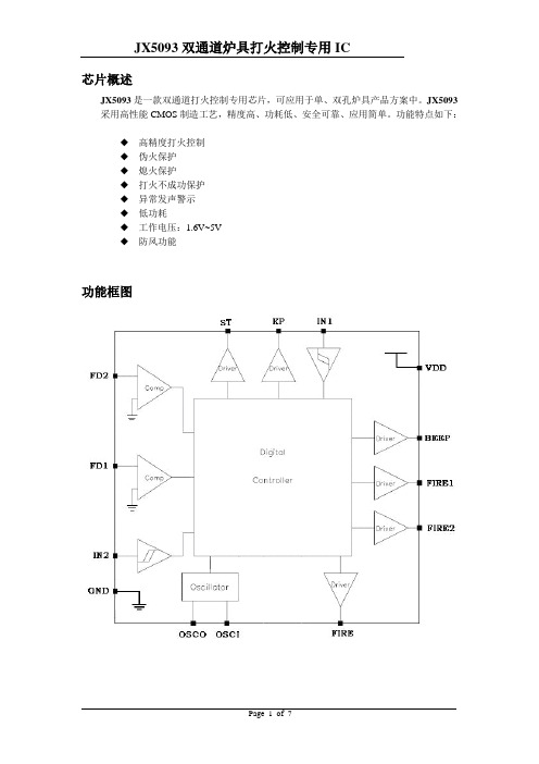
芯片概述JX5093是一款双通道打火控制专用芯片,可应用于单、双孔炉具产品方案中。
JX5093采用高性能CMOS制造工艺,精度高、功耗低、安全可靠、应用简单。
功能特点如下:◆高精度打火控制◆伪火保护◆熄火保护◆打火不成功保护◆异常发声警示◆低功耗◆工作电压:1.6V~5V◆防风功能功能框图芯片管脚定义编号 名称 输入/输出描述 1 GND -芯片地 2 ST O 磁阀启动线圈驱动端 3 KP O 磁阀维持线圈驱动端4 IN1 I ①路启动端5 IN2 I ②路启动端6 OSCO O 内部振荡器输出7 OSCI I 内部振荡器输入8 BEEP O 外部蜂鸣器驱动端9 FD2 I ②路火焰探测端 10 FD1 I ①路火焰探测端 11 FIRE O 火焰确认端 12 FIRE2 O ②路打火控制端 13 FIRE1 O ①路打火控制端 14VDD-芯片电源JX50939工作原理1)正常A)单路打火单路打火指仅启动一路打火;或者前一路打火成功后再启动另一路打火。
备注:图中,ST脉冲宽度为500ms。
B)双路打火双路打火指启动一路打火后,在7s内启动另一路打火;或者同时启动两路打火。
双路打火交叠期间,即从后一路启动开始,到任一路打火成功,FIRE1、FIRE2并不同时为H,而是交替为H,交替周期500ms。
2)异常报警A)伪火保护若①路启动端IN1由H置L时,①路探测端为负压;或②路启动端IN2由H置L时,②路探测端为负压。
则进入伪火保护状态。
KP、ST、FIRE1或FIRE2均为L。
BEEP驱动蜂鸣器发出“嘟……嘟……嘟……”报警声,至IN1、IN2全置H方停。
B)熄火保护打火成功后,若①路启动端IN1为L时,①路检测到正压;或②路启动端IN2为L时,②路检测到正压。
则进入熄火保护状态。
KP置L,关掉磁阀。
BEEP驱动蜂鸣器发出“嘟嘟……嘟嘟……嘟嘟……”报警声,至IN1、IN2全置H方停。
C)打火不成功保护若①路启动端IN1由H置L后,经过7s,①路探测端仍为正压;或②路启动端IN2由H置L后,经过7s,②路探测端仍为正压。
- 1、下载文档前请自行甄别文档内容的完整性,平台不提供额外的编辑、内容补充、找答案等附加服务。
- 2、"仅部分预览"的文档,不可在线预览部分如存在完整性等问题,可反馈申请退款(可完整预览的文档不适用该条件!)。
- 3、如文档侵犯您的权益,请联系客服反馈,我们会尽快为您处理(人工客服工作时间:9:00-18:30)。
排除方法
1、修理电路 2、更换损坏的保险管 拧紧漏气点 1、拧紧漏气点 2、重新配置样品 3、重新设置 1、更换针头
2、更换密封圈重新紧固 3、重新设定正确的温度 4、可用标准溶液直接进色谱
1、老化色谱柱 2、活化解析管 3、长时间吹解析仪 4、请使用符合标准的解析管 5、适当降低解析温度
附录: JX-3热解析的操作方法 以下涉及到的仪器名词请对照 四、仪器各部位名称 第一步:温度的设置: 在开机自检完成界面,按设置键进入设定状态:
BCHP 1. 按 和 设定解析温度,然后按设置键;
2. 按 和 设定阀箱温度,然后按设置键; 3. 按 和 设定管路温度,然后按设置键; 4. 按 和 设定标定时间,然后按设置键; 5. 按 和 设定解析时间,然后按设置键; 6. 按 和 设定进样时间,然后按设置键; 7. 按停止键退出设定状态返回到自检完成状态。 第二步:仪器的运行: 1. 在开机自检完成界面,按运行键进入加热准备状态界面,等待解
七、 仪器主要技术参数:
受控文件 温控范围: 控温精度: 解析压力: 标定模拟采样流量: 解析时间及进样时间: 重复性:
室温—380℃ ±1℃ 0—0.4MPa 0—100ml/min 1秒至60分00秒可调 >95%
解析管规格:
直径Φ6mm; 长>120mm
使用电压:
220V±10% 50—60Hz
1. 将氮气接入解析仪背面的进气口。 2. 密封热解析仪上的载气进口。
BCHP 3. 将解析仪废气出口放空。
4. 将进样针头插入到气相色谱的进样口。 5. 关闭气相色谱的载气柱前压。 6. 调整解析仪前面板上稳压阀,观察气相色谱的载气柱前压压力
表,其压力要与气相色谱的载气柱前压一致。 7. 全部连接完成后即可进行样品分析。 (解析仪的操作方法请参考说明书)
3
八、仪器成套性:
1 JX-3热解析仪
1台
2 备件
电源线
1根
BCHP 进样针头 解析管密封圈 气路密封圈 三通接头 两通接头 标定进样口密封垫 进口软气路管
Φ0.7mm Φ10×2.4 Φ6×5 铜质 铜质 Φ6 Φ3×2m
3根 10个 5个 1套 1套 3个 1根
加热盒锁扣
1套
Tenax TA吸附管
实际样品的解析操作方法 1. 将采集好样品的解析管分别与左右两侧的锁紧手轮连接,并
用力拧紧,确保不漏气。
7
2. 将解析管放入加热盒中,将加热盒锁闭,按下运行按钮,热解 析仪将自动执行解析的全过程至进样结束。 3. 进样完成后就可将解析管取出,等待做下一个样品。
小技巧:在进样完成后可直接按下标定按钮,即可实现单支解析管的活
中带有电子流量稳定的色谱连接方法。 产品满足国标 《GB/T 18883-2002》 产品满足国标 《GB/T 50325-2001》(2006版) 企业通过ISO9001:2008质量管理体系认证
产品通过CE认证
产品通过国家分析仪器质量监督检验中心检测
受控文件 产品通过国家标准物质检测中心检测 产品荣获部级科技进步二等奖
受控文件 3. 在状态就绪界面,按运行键,仪器进入解析、进样(自动完成) 状态,仪器会根据您的设置自动运行,在解析、进样完毕后自动 退出,并返回到状态就绪界面。
在设定状态界面下反复按设置键可循环选择各个设置。
在就绪状态界面下长时间按停止键可退回到自检完成状态界面,同时仪器降温。
第三步:安装保温传输进样管进样针: 在备件中取出针头,将针头与保温进样管连接并拧紧螺帽以防漏气。 (密封件用0.32的石墨压环) 第四步:调整热解析载气压力:
受控文件 八、仪器成套性 ………………………………………………(4)
九、制造商保证 ………………………………………………(4) 十、故障现象与排除方法 ……………………………………(5)
附录…………………………………………………………(6)
一、 公司介绍: 北京中惠普分析技术研究所成立于1994年,是一所集科、工、贸
2支
保险管 不锈钢气路
2A
1只
Φ1.6
1米
3 产品使用说明书
1本
受控文件 4 产品合格证
1份
5 产品保修卡
1份
九、制造商保证: 在用户遵守保管和使用规定的条件下,以制造商发货给用户之日起十
二个月内,产品因制造质量不良更换零部件或修理产品,我所无偿为用户 更换零部件或修理产品。
仪器如有问题请有我所技术服务中心联系:
析温度、阀箱温度和管路温度分别达到各自的设定温度,然后仪 器进入状态就绪界面。(按状态键可随时查看实时温度) 2. 在状态就绪界面,按标定键,仪器进入标定状态(吹扫状态), 仪器会根据您的设置自动运行,待标定结束后有提示界面,按停 止键退出,返回到状态就绪界面。(标定状态中按停止键可直接 退出并返回到状态就绪界面)
于一体的高新技术企业,是国内规模最大的气相色谱仪气源发生器的 配套厂家,产品涵盖高纯度氢气、高纯度氮气、低噪声空气源等各种
BCHP 流量单体机及各种相关组合机。系列全,品种多。最近又推出供科学
研究用超纯氢提纯仪,氢气纯度可达99.99999%和纯氧发生器、热解析 仪、等多种产品。我所于国内首推的小型全自动氢气站更是解决了中 心实验室安全集中供氢的难题。
连接方法二:(此方法是用气相色谱的载气控制热解析仪,需要对 色谱的气路进行改动)
1. 将前面板上的稳压阀关闭(左旋),此方法不需要解析仪控制色 谱气路。
2. 将氮气接入解析仪背面的进气口。 3. 找到进样口前的载气管路,用截管器(或小钢锉)将其割断,注
意截断面的平齐,然后将出气的一端接到热解析仪的载气进口。
BCHP
BCHP JX-3型热解析仪 使 用 说
受控文件 明 书 北京中惠普分析技术研究所
在使用仪器前,请您认真阅读此使用说明。 敬告: 1、加热盒温度较高请避免直接接触加热体 2、请使用符合标准的解吸管;为了达到最佳的分析效果建议
BCHP 使用不锈钢Tenax解析管
3、载气(氮气)请使用钢瓶气 4、有EPC或其他电子流量稳定电路的气相色谱仪请参考附录
1. 将热解析的载气压力调整至和气相色谱相同。 2. 关闭气相色谱的载气。 3. 将热解析仪的保温传输进样管进样针插入气相色谱的进样
6
器,调整热解析仪稳压阀,观察气相色谱的载气压力表,设 定所需压力。 第五步:调整吹扫气的流量: 1. 按下键盘上的标定按钮。 2. 调整浮子流量计流量调节旋钮,将流量调节到所需流量(或 参考国标),转子流量计调整范围0-100ml/min。
电话:(010)68033419,68033420,68033421
4
BCHP
受控文件
5
十、仪器的故障原因与排除方法:
故障现象 仪器不能启动 进样出峰小 重复性差
进样不出峰 或响应值小
进样杂峰多
故障原因
1、电路没有接通 2、保险管坏 气路连接处漏气 1、气路系统漏气 3、样品配置不准 3、加热时间不一致 1、进样针头堵
原气相色谱的任何部件及操作条件。
三、 工作原理 将采集有一定体积样品的Tenax吸附管置于热解析仪中加热,解析
被吸附物质。通过保温传输管,导入毛细管气相色谱仪进行分析,用 保留时间定性,峰高及峰面积定量。
1
四、 仪器各部位名称:
1、
7、
2、
8、
3、
9、
BCHP 4、
5、 6、
1、保温传输进样管及进样针 2、加热盒 3、液晶显示屏 4、控制面板
BCHP 以上五步是热解析的准备工作。 标准样品的解析操作方法 第一步:必须的用品:
1. 准备TVOC标准溶液(国家标准物质中心购买或其他)。 2. 活化好的Tenax 吸附管一支。 3. 微量进样器一支。 第二步:进样操作: 1. 按标定键,进入标定状态(吹扫状态) 2. 将长度不小于120mm的Tenax 解析管与热解析仪两侧的锁紧手
2、锁紧手轮没紧固漏气 3、样品箱没加热或温度低 4、色谱仪有问题
1、色谱柱需要老化 2、解析管需要活化 3、解析仪需要吹扫 4、解析管品质问题 5、解析温度过高
检查方法
1、检查电路 2、检查保险管 用检漏液检测各气路连接处。 1、检查管路
1、用外径为0.3mm的细丝疏通 进样针头
2、重新紧固手轮和解析管 3、检查设置 4、检查色谱仪是否正常
10、 11、 12、
9开关
13、 14、 15、
5、浮子流量计及流量调节
13、色谱工作站启动串口
6、载气压力表
14、色谱载气进气口
7、快速锁紧手轮
15、氮气进气口
8、标定进样口
五、 仪器安装与使用:
受控文件 1、 启动前的准备: 将仪器从包装箱内取出,检查有无因运输不当而造成的损坏,核 对仪器备件、合格证及保修卡是否齐全。 2、 仪器的安装与调节: a) 请将氮气与热解析载气进气口(14)连接。 b) 用色谱工作站连接线将热解析仪与色谱工作站启动按钮的接线口
我们坚持质量第一,用户至上的服务准则,产品遍及全国,并出 口挪威、阿根廷、韩国、乌克兰等18个国家和地区。
二、 概述: JX-3型热解析仪是一种样品前处理装置,是在我所生产的JX-2型
的基础上研制而成的。它可使气相色谱仪的应用范围大大扩展。
受控文件 JX-3型热解析仪可应用于任何型号的气相色谱仪,并且不需改动
BCHP 受控文件
BCHP
受控文件 北京中惠普分析技术研究所
地址:北京市西城区广安门外天宁寺前街2号北院F座 电话:(010)68033419 68033420 68033421 传真:(010)68033367 邮编:100055 Email: sales@ ; support@ 网站:
轮连接,用力锁紧确保不漏气。 3. 用微量进样器取TVOC标准溶液1ul(根据样品浓度),从右侧
