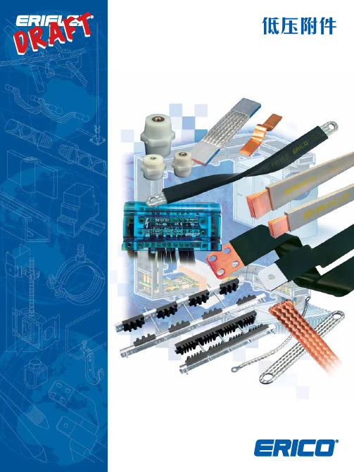
QFlex 中文产品彩页2009
microflexOperatorManual_Chinese
Am29LV640DH90REEN资料
Continuity of Specifications
There is no change to this datasheet as a result of offering the device as a Spansion product. Any changes that have been made are the result of normal datasheet improvement and are noted in the document revision summary, where supported. Future routine revisions will occur when appropriate, and changes will be noted in a revision sumtion
Please contact your local AMD or Fujitsu sales office for additional information about Spansion memory solutions.
Publication Number 22366 Revision B
Continuity of Ordering Part Numbers
AMD and Fujitsu continue to support existing part numbers beginning with “Am” and “MBM”. To order these products, please use only the Ordering Part Numbers listed in this document.
Publication# 22366 Rev: B Amendment/+8 Issue Date: September 20, 2002
Leica FlexLine TS02 TS06 TS09仪器 说明书

FlexLine, 12 251 251 252 254 256 257 257 258 259 264 268 270 271 树状菜单结构 目录结构 275 278 279
14.6 14.7 14.8
15 国际质保 , 软件许可协议 16 术语 附录 A 附录 B 索引
1
1.1
主要组件
系统描述
11 检验 & 校准 11.1 11.2 11.3 11.4 11.5 概述 准备工作 校准视准误差和竖直角指标差 校准横轴倾斜轴系误差 校准仪器和基座的圆水准器
11.6 11.7
检验 仪器激光对中器 三脚架维修
224 225 226 226 227 228 229 229 229 230 231 231 236 236 237 239 243 244 247 249
115 118 122 122 122 124 126 130 133 140 142 142 142 144 146 146 146 148 150 152 153 158 158 160 167 170 FlexLine, 9
目录
目录 9.13.5 子程序检查 9.13.6 子程序放样边坡 9.13.7 子程序检查边坡 导线测量 (欧美版) 9.14.1 概述 9.14.2 开始和配置导线测量 9.14.3 测量导线 9.14.4 继续 9.14.5 闭合导线 参考面
a) 特定按键 b) 导航键 c) 输入回车键 按键 按键 说明
d) ESC 键 e) 功能键 F1 到 F4 f) 字母数字键区
翻页键。 当有多页可用时显示下一屏。 FNC 键。 快速进入测量辅助功能。
按键
说明 用户自定义键 1。在 FNC 目录中可自已定义功能。 用户自定义键 2。在 FNC 目录中可自已定义功能。 导航键。 在屏幕上移动光标并进入特定域。 输入回车键。 确定输入,然后到下一个域。 ESC 键。 不做任何更改的退出当前屏或编辑模式。 回到高一级的目录。
ADS 2009
ADS 2009可改善专案管理、即时放大和平移、互动式3D布局检视、stretching(缩放)和cut plane(剖面)显示等功能;改良LVS(布局vs.线路图)设计同步功能,并提供自动化设计的完整控制功能,以确保布局的正确性;并更新设计规则检查功能,可以快速地将绘图汇出/汇入,让设计到生产的移转过程更加顺利。
我们本着诚信交易,节约中小企业的生产生本,致力于科技信息化发展
需要软件请联系我们QQ客服:394623568 客服电话:13294332477
点击直接咨询:/ (或把网址复制到你的IE地址栏中直接对话,人工在线)
说明:软件非免费提供下载,所有软件都是本人付费后得到的软件,软件都经过安装测试,完全可以无任何功能限制使用,如有需要请联系本人邮件或是QQ,联系时请写明你的姓名和地址,需要什么可以在列表中选择(按CTRL+F输入关键字在网页中模糊查询),或是来邮件说明具体软件名称,我会在第一时间回复您,如不能得到即时回复,请换个邮件联系我,谢谢。
QQ客服:394623568 客服电话:13294332477 MSN:caxcai@
客服邮件(Email): caxcai@ caxcai@ ; caxcai@ ; caxcai@
****************************************************************************
·WhatIF -- 用于射频系统结构的中频(IF)规划工具;
·Spectrasys -- 具有因果分析的唯一一种连续谱射频系统仿真器;
·Synthesis -- 实现可制造电路级设计的8种设计辅助工具,如为射频电路板设计精密镜像抑制滤波器。
突破性时域仿真技术
2009年Kemper产品目录:焊接、切割等说明书

welding, cutting and more...High-vacuum extraction . KEMPER Dusty (27). Mini-Weldmaster (28). High-vacuum cartridge filter (29)· Accessories ............................... 30 - 31· High-vacuum extractionand filter unit (32)26Ultra light, flexible and powerful.These are only some properties of this small power pack.Two strong turbines provide an excellent extraction efficiencyand high static pressing. The minimum weight makes it veryflexible and universal for many different applications.A Kem Tex® ePTFE membrane filter cartridge provides thefiltration of superfine dust below 0.1 μm. Thereby this unitis suitable for the separation of alveole exchangeable dusts.The advantage of surface filtration is that the filtercartridge can be cleaned.In case of the Dusty, this happens manually in that minutewhen an essential cleaning will be indicated by theinstrument itself. The collected dust can be removed easilyfrom the lower part of the unit.Different nozzles, welding torches with integrated extraction ormini exhaust arms of the extensive accessory programme canbe connected to the two lugs of this extraction and filter unit.The extraction performance can be controlled steplessly andelectronically.For further accessories see pages 30/31. KEMPER DustyPart No.Description63 100KEMPER Dusty1.6 kW · 1 x 230 V / 50 HzVoltage: 1 x 230 V / 50 HzExtraction performance:340 m³/hMotor power: 1.6 kWNoise level:74 dB (A)Filter efficiency:> 99.9 %Weight:21 kgDimensions (w x d x h):300 x 300 x 690 mmTechnical dataPart No.Description10 902 44Spare filter for KEMPER DustySpare filter69mm300m m300mm₤1,197.00₤309.7027Mini-WeldmasterThis easy to transport high vacuum extraction and filterunit is ideal for the extraction of welding fumes at frequently changing work places.Extraction hoses with a diameter of 45 mm guarantee application at locations difficult to access.Various extraction nozzles with a magnetic foot are available.It is also possible to connect one or two welding torches with integrated extraction.The Mini-Weldmaster is equipped with a two stage filter and has a filter efficiency of 99.9 %. It is also possible to retrofit the unit with an activated charcoal filter. Cleaning of the filter inserts is not necessary.Depending on the actual operating time and the substances to be captured the filter has to be changed once or twice a year.A filter monitor indicates a necessary filter change.For more convenient handling a trolley with castor wheels and an automatic start-stop is available.For further accessories see pages 30/31.Part No.Description10 900 34Pre-filter mats, (10 per set)10 900 09Main filter10 900 08Activated charcoal filterSpare filtersVoltage:1 x 230 V / 50 Hz 3 x 400 V / 50 Hz Extraction performance:340 m³/h 270 m³/h Motor power: 1.6 kW 1.1 kW Noise level:71 dB (A)71 dB (A)Filter efficiency:> 99,9 % according to BGIA classification M Weight:24 kg 28 kgDimensions (w x d x h):340 x 450 x 660 mm 340 x 450 x 660 mmTechnical dataPart No.Description 91 730Mini-Weldmaster1.6 kW · 1 x 230 V / 50 Hz 91 730 100Mini-Weldmaster1.1 kW · 3 x 400 V / 50 Hz91 731Mini-Weldmaster with activated charcoal 1.6 kW · 1 x 230 V / 50 Hz91 731 100Mini-Weldmaster with activated charcoal 1.1 kW · 3 x 400 V / 50 HzUnits₤37.30116.40233.60₤1,330.002,659.001,563.002,893.0028With its four air intakes this mobile extraction and filter unit offers a flexible unit for the extraction of polluted air directly at source.It can be used on multiple operations in the metal working industry.The unit can be connected to exhaust nozzles, mini exhaust arms or shields with integrated extraction. The use of torches with integrated extraction makes it even more flexible.The robust extraction unit is supplied with two Kem Tex ® ePTFE membrane filter cartridges, which are monitored by the electrical control and – according to the saturation rate –cleaned automatically during operation.The extraction capacity can be controlled by a stepless adjustable speed control.For further accessories see pages 30/31.High-vacuum cartridge filter unit, mobilePart No.Description82 600High-vacuum cartridge filter unit, mobile 3.3 kW · 3 x 400 V / 50 Hz 94 102 600 02Sensor clamp for the automatic start-stopFan performance:max. 600 m³/h Motor power: 3.3 kW Amperage:7 APressure:20,000 PaVoltage:3 x 400 V / 50 Hz Filter efficiency:> 99,9 %(BGIA classification M)for info on filter cartridges see page 33Compressed air supply: 3.0 - 5.0 bar Weight:178 kg Dimensions (w x d x h):655 x 825 x 1,315 mm Noise level:70 dB (A)Technical dataPart No.Description 10 902 44Spare filter forhigh-vacuum cartridge filter unit, mobileSpare filter₤6,683.00495.60₤309.7029AccessoriesTrolleyPart No.Description91 750 200Trolley for Mini-Weldmaster incl. 4 guide rollers, with brakesExtraction hosePart No.Description93 070 004Extraction hose Ø 45 mm, length: 2.5 m 93 070 005Extraction hose Ø 45 mm, length: 5.0 m 93 070 006Extraction hose Ø 45 mm, length: 10.0 mSlit nozzle 300 mmPart No.Description23 200 08Slit nozzle, 300 mm, with magnetic footSlit nozzle 600 mmPart No.Description23 200 09Slit nozzle, 600 mm, with magnetic footFunnel nozzlePart No.Description23 200 10Funnel nozzle flexible, with magnetic footWelding shieldPart No.Description280 010 030Welding shield with integrated extraction₤49.9098.70191.10₤119.50₤128.80₤126.80₤101.80₤89.8030AccessoriesAdaptor for welding torchesFor connection with a hose, Ø 45 mm.Part No.Description10 600 71Adaptor for welding torches with integrated extraction 42 - 44 mm 10 601 04Adaptor for welding torches with integrated extraction 39 - 42 mm 10 600 84Adaptor for welding torches with integrated extraction 30 - 38 mmMini-Exhaust armPart No.Description91 350Exhaust arm, Ø 50 mm, length: 740 mm, without exhaust nozzle, swivelling to all directions, tubes made of aluminium,joints made of molded plastic incl. standard fixing device.Other exhaust arm diameters on request.Mounting bracketsPart No.Description93 008 001Table mounting bracket incl. two screw clamps 93 008 002Wall mounting bracket incl. screws and rawlplugsNozzlesPart No.Description232 0002Slit nozzle, width 200 mm 232 0004Tube nozzle, Ø 50 mm232 0005Plexiglass nozzle, 245 x 220 mm232 0006Funnel nozzle, round, extraction hole Ø 210 mm₤7.307.307.30₤220.20₤44.5032.50₤54.9019.1068.4064.2031High-vacuum extraction and filter unitPart No.:91 0100 20091 0200 20091 0300 200Filter cartridges:Kem Tex ®ePTFE-membrane filter for surface filtration Filter efficiency:> 99.99 % according to BGIA classification L, M Filter efficiency:For alveole exchangeable dusts see page 33Extraction performance:3,300 m³/h 4,000 m³/h 4,500 m³/h Pressure:18,000 Pa 18,000 Pa 20,000 Pa Motor power:22.0 kW 30.0 kW 37.0 kW Voltage:3 x 400 V / 50 Hz 3 x 400 V / 50 Hz 3 x 400 V / 50 Hz Compressed air supply: 5.0 to 6.0 bar 5.0 to 6.0 bar 5.0 to 6.0 bar Weight:1,050 kg 1,150 kg 1,350 kg Dimensions (w x d x h):2,375 x 1,413 x 2,015 mm 2,826 x 1,413 x 2,015 mm 3,277 x 1,413 x 2,015 mmTechnical dataHigh-vacuum extraction and filter units of the system 9000are very suitable for the connection of several extraction elements and for the construction of central extraction systems for welding workshops, grinding shops or the like.The extracted harmful substances will be separated at the surface of the Kem Tex ® ePTFE membrane filter. The control,based on a Siemens Simatec S7, monitors the collected dust on the surface of the cartridges. On reaching a certain limit it automatically activates the cleaning process during operation of the unit.The robust filter unit, contructed of reinforced steel panels,consists of two parts being connected on site.The following table gives an overview of the standard units.Units with higher outputs are available.For further information on extraction and filtration unitssystem 9000 see pages 70 to 82.32Due to the Kem Tex ® ePTFE membrane filter the KEMPER extraction and filtration systems act as reference for all extraction units.KEMPER extraction and filtration systems are yet efficient where other filtration units are no longer able to filter even the smallest particles. Especially the range of particle sizes smaller than 0.4 μm is very important for the filtration of dusts generated during welding and cutting processes. Because the particles below 0.4 μm are alveole exchangeable.Pulmonary alveoli are the smallest units in the human lung where oxygen is exchanged between the inhaled air and the human blood. Particles reaching the pulmonary alveoli can also diffuse into the bloodstream, form deposits all over the body and, depending on the chemical structure of the particles, can cause cancer.It is absolutely essential for extraction and filtration systems to filter even those finest particles since it is the only possibility to protect your employees and yourself against serious diseases.The BGIA (German government safety organisation) tests on the particle size distribution of welding smoke has shown the following results (E308-16).The Kem Tex ® ePTFE membrane filters can filter particles smaller than 0.4 μm, which represent 98.9 % of the total dust particles, according to BGIA tests.The effective pore size of the Kem Tex ® ePTFE membrane filter is that small, that even particles with 0.1 μm already will be filtered up to 92 %. The equal zero-emission of the Kem Tex ®ePTFE membrane surpasses all current regulations even for superfine particles. Especially with superfine dusts theKem Tex ® ePTFE membrane filters prevent a penetration of the particles.Kem Tex ® ePTFE membrane filters are therefore the ultimate technology concerning all applications. They are yet efficient where conventional filters of the filter class “M” reach their limit. About 90 % less particles reach the air in comparison with conventional filters.Trust in the experience of KEMPER and keep your air clean with Kem Tex ® ePTFE membrane filters!KemTex ® ePTFE membrane filterParticles Ø in μm <0.2<0.4<0.6<0.8<1.0>1.0Quantity 8002519012% of the quantity 75.323.60.900.10.2% of the mass15.938.77.58.229.733Your distributor:P a r t N o . 691 2440-3 · P r i n t e d o n e c o l o g i c a l l y b e n e fi c i a l p a p e r .All prices are exclusive of the current VAT.Priced catalogue items will be delivered carriage paid, within the EU (mainland),incl. packaging. For orders below a net price of £400.00, a standard carriage charge of £15.00ex. VAT, for packaging, insurance and carriage will be raised.All orders are subject to our conditions of sale.Price and technical specifi cations are subject to change without notice. We do not accept any liability for misprints. With the publication of this price list, all former price list loose there validity.The technical specifi cations stated in our catalogue are subject to change withoutnotice. This catalogue is protected by copyright and remains our property.This catalogue can be reclaimed at anytime.Reprints, or partial reprints can only beaccepted with written authorisation by KEMPER .KEMPER (U.K.) Ltd. · Venture Court · 2 Debdale Road · Wellingborough · Northamptonshire NN85AA·Tel.01327872909·Fax01327872181·**************.uk·。
Bridgelux Vesta Flex 双通道控制模块说明书

® Flex Product Data Sheet DS 460Vesta Flex PlatformThe Bridgelux Vesta Flex Dual Channel Driver and Control Module family is a bundled system, guaranteed to work together out of the box, that enables seamless control of the Bridgelux Vesta Series Tunable White Arrays and Modules. The Driver's high resolution dimming and tuning algorithm provides for smooth and flicker-free CCT tuning, dimming to 0.1%, and dim-to-off. These specification grade drivers and control modules are separate devices which, when connected via an ethernet cable, form a smart and flexible lighting control system. These Vesta Flex Control Modules are intended for use with a Vesta Flex Dual Channel Driver and to be factory installed as incorporated products. The platform offers a number of driver and control module options to choose from, enabling application flexibility and interoperability with third party systems. These different control modules support wired control protocols such as DALI-2 DT8 and 0-10V as well as wireless control protocols with WiFi and Bluetooth mesh. These platforms come with ready-built iOS and Android apps and web portals which provide for commissioning, light management, and services designed to expand the capability of modern lighting systems. Vesta Flex is a future-ready solution, designed to quickly adapt to new control systems without requiring luminaire recertification.Vesta Flex Platform OverviewVesta FlexControlModuleLighting systems with 0-10V wired control devicesThe Vesta Flex Dual 0-10V Control Module is compatible with industry standard 0-10V, 1-10V current sourcing or current sinking wired control devices. The Control Module provides for two-channel control of color temperature and intensity.Product Feature MapBridgelux Vesta Flex Control Module features a control port with an RJ45 terminal which enables plug-and-playconnectivity with any Vesta Flex Dual Channel Driver control port. The Control Module receives auxiliary power from the Driver via the RJ45 control port and communicates with the Driver via a dual channel PWM signal.The control module receives its control inputs via two pairs of analog 0-10V signal wires, one pair for intensity dimming and one pair for CCT tuning.Please visit for more information on compatible Vesta Flex Dual Channel Driver and Vesta Series Tunable White arrays and modules.Product NomenclatureThe part number designation for Bridgelux Vesta Flex Dual 0-10V Control Module is explained as follows:1,2,3,4 5,6,7, 9,10,11, 14,15, 16Product FamilyBXCS = Control & SensorsProduct Version 02 = Version 2Output Protocol P = PWMMounting holesInput Voltage12 = 12VBXCSN2P02A----Control port compatible with Ves-ta Flex Dual Channel Driver12AIntegrated SensorsN = NoneOutput Channels2 = Dual Channel (WW, CW)Control InputA = Analog (Dual 0-10V)Product Generation A = Generation A Poke-in connector for 0-10V controlsTable 2:Electrical CharacteristicsElectrical CharacteristicsVesta Flex Control Modules are designed to connect and communicate with all Vesta Flex Dual Channel Drivers out of the box. Any 8P8C category ethernet cable with RJ45 connectors may be used to connect the Control Module and the Driver via the RJ45 port. The communication between the control module and the driver is asymmetric. The Vesta Flex Dual Channel Driver will not work without this asymmetric communication signal from the Vesta Flex control module.The Vesta Flex Driver automatically detects which control module is connected to it and adjusts its settings accordingly. This feature allows to simply plug-and-play any Vesta Flex Control Module with any Vesta Flex Dual Channel Driver regardless of the chosen communication protocol on the Vesta Flex Control Module.Bridgelux recommends the use of an ethernet cable that is commonly available and recognized by the Telecommunica-tions Industries Association (TIA), e.g. Cat 5e, Cat 6 and Cat 6a cables.The maximum length of such an ethernet cable is 300m.Control Port ConnectionNotes for Figure 1:1. When the Vesta Flex 0-10V Control Module is dimmed down and thesignal voltage reaches 0.85V, then the Driver output power goes tozero and the Driver goes in standby mode. When the Control Module is dimmed up and the dimming control signal voltage reaches 0.95V, then the Driver exits standby mode and turns on its output power at minimum output current. That hysteresis prevents any potental flicker when the dimming control voltage drops below 1.0V.Control CharacteristicsTable 4:Control Signal CharacteristicsMinimum Dimming LevelOffOn from standby mode Offand standby modeDimming startFigure 1: Control Signal Dim-To-Off Hysteresis Lowest CCT Tuning LimitTuning startFigure 2: Control Signal at Lowest CCT LimitNotes for Figure 2:1. When the Vesta Flex 0-10V Control Module is tuned to its lowest CCT limit and the signal voltage drops below 1.0V, then Driver output maintains its current state resulting in a constant CCT at the lowest limit.Terminal ConfigurationInput TerminalFigure 3: Terminal ConfigurationControl PortNotes for Table 6:1. The - 0-10V Dim and the - 0-10V CCT terminals are internally connected to a common ground.Mechanical Characteristics Table 7:Control Module Mechanical CharacteristicsEnvironmental and Regulatory StandardsDesign ResourcesApplication NotesPlease contact your Bridgelux sales representative for assistance on obtaining application support when designing with the Bridgelux Vesta Flex Dual Channel Driver and Control Modules. For a list of available resources, visit .3D CAD ModelsCAD models depicting the Vesta Flex Wireless Control module are available in both IGES and STEP formats. Please contact your Bridgelux sales representative for assistance.PrecautionsCAUTION: PRODUCT HANDLINGHandle the Vesta Flex Control Module with care to prevent any damage from mechanical shock.It is recommended to handle this module in a static-free environment.Do not open or disassemble the product.To maintain product warranty, the installer is responsible for ensuring that the module's operating conditions do not exceed the maximum conditions stated within this data sheet.CAUTION: PRODUCT INSTALLATIONIncorrect installation of the Vesta Flex wireless control module can cause irreparable damage to the module, connected Vesta Flex Driver and/or connected LEDs.When connecting the Vesta Flex wireless control module with the Vesta Flex Dual Channel Driver, make sure that the RJ45 connectors are locked in the RJ45 ports.The product is intended for factory installation in a panel or into a controlled equipment.DisclaimersMINOR PRODUCT CHANGE POLICYThe rigorous qualification testing on products offered by Bridgelux provides performance assurance. Slight cosmetic changes that do not affect form, fit, or function may occur as Bridgelux continues product optimization.11About Bridgelux: Bridging Light and Life™© 2020 Bridgelux, Inc. All rights reserved 2020. Product specifications are subject to change without notice. Bridgelux, the Bridgelux stylized logo design and Vesta are regis -tered trademarks of Bridgelux, Inc. Bridging Light and Life is a trademark of Bridgelux, Inc. All other trademarks are the property of their respective owners.Bridgelux Vesta Flex Dual 0-10V Control Module Data Sheet DS460 Rev. B (10/2020)46430 Fremont BlvdFremont, CA 94538 USATel (925) 583-8400At Bridgelux, we help companies, industries and people experience the power and possibilityof light. Since 2002, we’ve designed LED solutions that are high performing, energy efficient,cost effective and easy to integrate. Our focus is on light’s impact on human behavior, deliveringproducts that create better environments, experiences and returns—both experiential andfinancial. And our patented technology drives new platforms for commercial and industrialluminaires.For more information about the company, please visit /Bridgelux /Bridgelux /user/Bridgelux /company/bridgelux WeChat ID: BridgeluxInChina。
艾默生全产品宣传彩页

艾默生工业自动化产品及解决方案品质卓越全球领先的行行出众的控制技术目录变频器EV800高性能灵巧型变频器 (1)EV1000、EV2000通用变频器 (2)EV3000高性能矢量控制变频器 (4)TD2100 供水专用变频器 (5)EV3100、TD3100电梯专用变频器 (6)TD3200异步门机专用变频器、EV3200同步/异步门机专用变频器 (7)TD3300 张力控制专用变频器 (8)TD3400注塑机专用变频器 (9)SK高性能可编程变频器 (10)SP高性能系统解方案产品平台 (11)通讯组件 (12)制动组件 (13)可编程控制器EC系列可编程控制器 (14)ETC多路智能温控器 (17)EZ600文本显示器 (18)ControlStar编程软件 (19)EV800高性能灵巧型变频器控制领先内置无速度传感器矢量控制和V/F 两种控制方式精确的电机参数自辨识模型优化的空间电压矢量调制方式结构紧凑控制电路与主电路的集成设计高可靠性的线板插接工艺75×154×145mm 3业界超薄尺寸设计灵活最简单的按键设计,多功能模式键,一键多用简单的电子开关设定,即可完成I/O 的类型转换与功能配置安装便捷独特的I/O 端子压接方式方便的DIN 导轨式安装架构绿色环保输入谐波含量低,位移因数COS φ >0.97 低噪音设计,最大开关频率达18kHz●●●●●●●●●●●●型号EV800-2S0002G 2S0004G 2S0005G 2S0007G 2D0011G 2D0015G 2D0022G 适配电机(kW )0.250.370.550.75 1.1 1.5 2.2输出规格额定输出电流(A ) 1.7 2.2 3.0 4.0 5.27.09.6输出频率(Hz )0~1500过载能力150%额定负载1分钟输入电源相数、电压、频率单相,200/240V ;50/60Hz 三相,200/240V ;50/60Hz 允许电压波动-10%~+10%允许频率波动48~62Hz 型号EV800-4T0004G 4T0005G 4T0007G 4T0011G 4T0015G 4T0022G 4T0030G 4T0037G 适配电机(kW )0.370.550.75 1.1 1.5 2.2 3.0 3.7输出规格额定输出电流(A ) 1.3 1.7 2.1 2.8 3.8 5.17.29.0输出频率(Hz )0~1500过载能力150%额定负载1分钟输入电源相数、电压、频率三相,380/480V ;50/60Hz 允许电压波动-10%~+10%允许频率波动48~62Hz1规格与型号通用变频器优异的控制性能磁通矢量PWM 调制电机参数自整定(静止与旋转)调速范围达1:100(EV1000为1:50)起动转矩0.50Hz 时180%额定转矩(EV1000 1Hz 时150%)转矩自动提升与手动提升功能可选多种行业专用功能PI 过程闭环,多段速,简易PLC ,纺织摆频定长控制,运行时间累计功能高速脉冲输入输出功能特长加减速时间功能优良的环境适应能力专业“瞬停不停”算法,应对电网晃电自动限流技术、自动频率调节技术,应对负载突变所有单板进行“三防漆”防护,提高变频器防潮湿、粉尘和油污能力独立风道设计,提高抗粉尘环境音调调整技术,全面改善噪声丰富的标准配置内置脉冲编码器接口RS232/RS485标准通信接口,支持MODBUS 协议EV1000全系列标配制动单元,EV2000 7.5kW 以下配置制动单元●●●●●●●●●●●●●●●●●摆频示意图23通用变频器EV2000 (55P 及以下)系列EV2000 (55G 及以上)系列型号EV2000-4T 0055G/0075P 0075G/0011P0110G/0150P 0150G/0185P 0185G1/0220P10220G1/0300P10300G1/0370P1 0370G1/0450P10450P1/0550P1适配电机(kW ) 5.5/7.57.5/1111/1515/18.518.5/2222/3030/3737/4545/55额定容量(kVA )8.5/1111/1717/2121/2424/3030/4040/5050/6060/72输出规格额定输出电流(A )13/1717/2525/3232/3737/4545/6060/7575/9090/110输出频率(Hz )0~650过载能力G 型:150%额定电流1分钟,200%额定电流0.5秒P 型:110%额定电流1分钟,150%额定电流1秒输入电源相数、电压、频率三相,380/440V;50Hz/60Hz 允许电压波动持续波动不超过±10%,短暂波动不超过-15%~10%,电压失衡率:<3%允许频率波动±5%型号EV2000-4T0550G 0750G/0750P 0900G/0900P 1100G/1100P 1320G/1320P 1600G1/1600P 2000G/2000P 2200G/2200P 2800P 适配电机(kW )557590110132160200220280额定容量(kVA )72100116138167200250280342输出规格额定输出电流(A )110152176210253304380426520输出频率(Hz )0~650过载能力G 型:150%额定电流1分钟,200%额定电流0.5秒P 型:110%额定电流1分钟,150%额定电流1秒输入电源相数、电压、频率三相,380/440V;50Hz/60Hz 允许电压波动320V ~460V 电压失衡率:<3%允许频率波动±5%型号EV1000-2S0004G 2S0007G 2S0015G 2S0022G 4T0007G 4T0015G 4T0022G 4T0037G/37P 4T0055G/55P 适配电机(kW )0.40.75 1.5 2.20.75 1.5 2.2 3.7 5.5额定容量(kVA )1.0 1.5 3.0 4.0 1.5 3.0 4.0 5.98.9输出规格额定输出电流(A )2.5 4.07.510.0 2.33.7 5.08.813.0输出频率(Hz )0~650过载能力150%额定电流1分钟, 180%额定电流1秒G 型:150%额定电流1分钟,180%额定电流3秒p 型:120%额定电流1分钟输入电源相数、电压、频率单相,200/240V;50Hz/60Hz 三相,380/440V;50Hz/60Hz允许电压波动-15%~+10%允许频率波动±5%规格与型号EV1000规格与型号型号EV3000-4T 0022G 0037G 0055G 0075G 0110G 0150G 0185G 0185G10220G 0220G10300G 0370G 0450G 0550G 0750G 0900G 1100G 1320G 1600G 2000G 2200G 适配电机(kW ) 2.2 3.7 5.57.5111518.518.52222303745557590110132160200220额定容量(kVA )3 5.58.51117212424303040506072100116138167200250280输出规格额定输出电流(A )581317253237374545607590110152176210253304380426输出频率(Hz )0~400过载能力150%额定电流2分钟,180%额定电流10秒输入电源相数、电压、频率三相,380V;50Hz/60Hz 三相,380V ~440V;50Hz/60Hz 允许电压波动320V ~460V;电压失衡率<3%允许频率波动±5%EV3000高性能矢量控制变频器卓越的控制性能先进的控制算法:支持有速度矢量控制、无速度矢量控制,V/F 控制速度控制精度:有速度时 ±0.05%,无速度时±0.5%速度控制范围:有速度时1:1000,无速度时1:100起动转矩:有速度时200%/0r p m ;无速度时150%/0.5Hz 丰富功能支持直接转矩控制,转矩与速度在线切换,速度方式下多模式转矩限定零伺服功能多段速、简易PLC 、PID 过程闭环等优越的系统配置逆变采用智能功率模块IPM ,集驱动、保护、功率变换于一体LCD/LED 中/英文面板,支持参数拷贝内置PG 卡,支持差动/推挽/集电极开路编码器脉冲输入22kW 及以下内置制动单元,无需外配,成本低●●●●●●●●●●●45TD2100 供水专用变频器特点TD2100供水专用变频=PLC+变频器无需配置PLC 或供水控制器,即可实现多种常用供水模式。
FAF简介-中文版 2009

振德 海天 日精 海天 德玛格 海天
13
Moulding Shop
14
Clean Workshop
15
冲压车间基本信息 :
冲压机明细(总台数:57台 冲压机明细 总台数:57台) 总台数:57
吨位 18T 10T 8T 厂商 布鲁德 YAMADA 立葉 布鲁德 25T 振力 英瑜 京利 30T 拉斯特 明斯特 35T 40T 50T 60T 110T 150T 160T 京利 振力 布鲁德 布鲁德 BOS 拉斯特 艾打 KOMATSU 艾打 台数 5 6 5 6 10 3 8 1 1 1 3 1 3 1 1 2 2 2
放电加工机床配合EROWA夹具可实现快速更换电极 加 夹具可实现快速更换电极,加 放电加工机床配合 夹具可实现快速更换电极 工精密度可达± 工精密度可达± 0.002MM.
12
注塑车间概况: 注塑车间概况
注塑车间( 48台 注塑车间(共48台)
区分
立式 (共15台)
注塑机明细
厂商
雅宝 住友 沙迪克 日精 日精 沙迪克
RF
WTB
HDMI
DDR
MINI PCI
LVDS
31
Product list (昆山工場) 昆山工場 工場)
32
Product list (昆山工場) 昆山工場 工場)
33
Product list (昆山工場) 昆山工場 工場)
34
Product list (浙江工場) 浙江工場 工場)
35
C3 产品生产过 程宣传方法
C4 产品生产 过程确认方 法
C5 生产流 程
C6 出货流 程
C7 客 户反 馈 信息及售 后服务
主流外资品牌2009年度主推产品汇总

主流外资品牌2009年度主推产品汇总
佚名
【期刊名称】《《机电信息》》
【年(卷),期】2009(000)012
【摘要】2009年度一开始,关于空调产品更新换代的消息就不断传来。
几乎所有品牌都不约而同地将年度新品的宣传定位转移到节能、高效上来,以应对不断变革的市场新变化。
特别是在美的高调推出了其强大的变频家族系列产品后,国内品牌之间关于变频的竞争越演越烈。
这个时候,与大多数国产品牌庞大产销能力相比,一直处于相对弱势的大部分外资品牌也不甘示弱,一方面加大了其在节能、高效方面的继续宣传,另一方面对其变频技术优势进行升级换代,包括松下、三菱电机、日立、三菱重工、富士通、东芝等在内的主流品牌或宣传停产定速空调,或破天荒地推出数量更多的变频空调。
本刊在此特别选择了松下、三菱电机、日立、三菱重工、富土通、东芝等主流品牌的年度主推产品进行汇总刊登。
【总页数】5页(P56-60)
【正文语种】中文
【中图分类】TM925.12
【相关文献】
1.中国服装品牌年度大奖华丽转身杰克·2009(第六届)中国服装品牌年度大奖揭晓 [J],
2.艾默生CT喜获“2009年度传动产品国际领先品牌“奖 [J], 无
3.北京福乐维生物技术有限公司产品被评为“2009年度影响力品牌奖” [J],
4.艾默生CT喜获“2009年度传动产品国际领先品牌”奖 [J], 李慧
5.兰菱重工海尔2009年度蝉联“设计师最信赖十大外资(合资)品牌” [J],因版权原因,仅展示原文概要,查看原文内容请购买。
FS2009 产品说明书
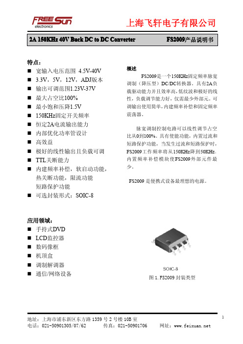
特点:�宽输入电压范围4.5V-40V� 3.3V,5V,12V,ADJ版本�输出可调范围1.23V-37V�最大占空比100%�最小饱和压降1.5V�150KHz固定开关频率�恒定2A电流输出能力�内部优化功率管设计�高效益�极好的线性输出且负载可调�TTL关断能力�内建频率补偿,软启动功能,热关断功能,限流功能短路保护功能�可选封装形式:SOIC-8应用领域:�手持式DVD �LCD监控器�数码像框�机顶盒�调制解调器�通信/网络设备概述FS2009是一个150KHz固定频率脉宽调制(降压型)DC/DC转换器。
具有2A负载驱动能力并且效率高,低纹波和极好的线性,负载调节能力好,仅需最少外部元。
可调输出使用简单,内建频率补偿和固定频率震荡器。
脉宽调制控制电路可以线性调节占空比从0到100%。
具有使能功能,内置过流和短路保护功能,当发生过流和短路保护时,FS2009工作频率将从150KHz降到50KHz。
内置频率补偿模块使FS2009外部元件最少。
FS2009是便携式设备最理想的电源。
图1.FS2009封装类型引脚设置图2.FS2009引脚结构(顶视图)表格1引脚描述引脚数引脚名描述1VIN 电压输入引脚,FS2009工作在直流电压4.5V到40V,输入外接适合大的旁路电容到地来消除输入噪声。
2OUTPUT 功率开关输出引脚(SW).输出端是提供功率输出的开关结点。
5-8GND 接地引脚,做版图时必须小心。
此引脚必须放置在硝特基二极管和输出电容到地的外面,来阻止电感电压引起的开关电流毛刺输入到FS2009。
3FB 反馈引脚(FB),通过外部电阻来分割回路,反馈是来检测和调节输出电压,反馈端电压是1.23V。
4EN 使能引脚。
驱动ON/OFF引脚为低电平则开启设备,驱动此引脚为高电平则关断设备。
功能模块图3:FS2009功能块方框图典型应用电路图4.FS2009典型应用电路12V-5V/2A最大额定值(注释1)注释1:工作在列表的最大额定值以上会造成器件永久损坏。
中文样本法国艾力锋
描述
TD 160 AL FC 100 x 32 FC 120 x 32 UD 80 A UDJ 125 A UDJ 160 A UD 250 A UD 400 A UDF 500 A FSJ FLG 250 FLG 400
第页
25 9 9 22 22 22 23 23 23 22 23 23
描述
UBS 1/5 TN UBS 4/5 TN UBS 4/5 T UBS 1/10 TN UBS 2/10 TN UBS 2/10 T UBS 3/10 TN 2 M 2 x 15,5 x 0,8 2 M 8 x 6 x 0,5 2 M 3 x 9 x 0,8 2 M 6 x 9 x 0,8 2 M 9 x 9 x 0,8 2 M 3 x 13 x 0,5 2 M 6 x 13 x 0,5 2 M 4 x 15,5 x 0,8 2 M 6 x 15,5 x 0,8 2 M 10 x 15,5 x 0,8 2 M 2 x 20 x 1 2 M 3 x 20 x 1 2 M 4 x 20 x 1 2 M 5 x 20 x 1 2 M 6 x 20 x 1 2 M 10 x 20 x 1 2 M 2 x 24 x 1 2 M 3 x 24 x 1 2 M 4 x 24 x 1 2 M 5 x 24 x 1 2 M 6 x 24 x 1 2 M 8 x 24 x 1 2 M 10 x 24 x 1 2 M 2 x 32 x 1 2 M 3 x 32 x 1 2 M 4 x 32 x 1 2 M 5 x 32 x 1 2 M 6 x 32 x 1 2 M 8 x 32 x 1 2 M 10 x 32 x 1 2 M 2 x 40 x 1 2 M 3 x 40 x 1 2 M 4 x 40 x 1 2 M 5 x 40 x 1 2 M 6 x 40 x 1 2 M 8 x 40 x 1 2 M 10 x 40 x 1 2 M 3 x 50 x 1 2 M 4 x 50 x 1 2 M 5 x 50 x 1 2 M 6 x 50 x 1 2 M 8 x 50 x 1 2 M 10 x 50 x 1 2 M 3 x 63 x 1 2 M 4 x 63 x 1 2 M 5 x 63 x 1 2 M 6 x 63 x 1 2 M 8 x 63 x 1 2 M 10 x 63 x 1 2 M 3 x 80 x 1 2 M 4 x 80 x 1 2 M 5 x 80 x 1 2 M 6 x 80 x 1 2 M 8 x 80 x 1 2 M 10 x 80 x 1
美国迪菲西电器公司产品说明书-模型702-N、702-NSE、702-NSS面包切片机

Grand Rapids, Michigan, U.S.A. 49504-5298USER’S OPERATING AND INSTRUCTION MANUAL ArrayMODEL 702-NMODEL 702-NSSBUN SLICERS0702S20000-CVMODEL 702-N, 702-NSE and 702-NSS BUN SLICERSSPECIFICATIONSDESCRIPTIONThese bun slicers have welded steel frames and stainless steel chutes. They are compact, durable slicers for counter top use in slicing a variety of buns with speed and economy.SPECIFICATIONS• Machine dimensions: Model 702-N• Machine dimensions: Model 702-NSEMODEL 702-N, 702-NSE and 702-NSS BUN SLICERS • Machine dimensions: Model 702-NSS• Weight: Approximately (70) pounds.• Standard Color: Gloss white enamel.•Standard Electrical Service:1/3 HP, 1725 RPM, 1-60-115 Volts AC, 6 Amps.•Optional Electrical Services:1/3 HP, 1725 RPM, 1-60-230 Volts AC, 3.5 Amps.1/3 HP, 1425 RPM, 1-50-220 Volts AC, 3.5 Amps.PRODUCT CAPACITIES•Maximum Product Size:4-7/8 inches Wide and 3 inches High•Blade Height (adjustable):5/8 inch to 1-1/2 inches•Maximum Cutting Depth:4-3/8 inchesMODEL 702-N, 702-NSE and 702-NSS BUN SLICERSSAFETY INSTRUCTIONSEvery effort has been made by Oliver Products Company to provide you with a safe machine. It is essential, however, that machine operators and maintenance personnel observe the following safety precautions.1. Before attempting to operate your slicer read this manual. Never allow an untrainedperson to operate this machine.2. Make sure that the machine is only connected to a properly grounded electricalsupply source of sufficient capacity for the load the slicer will put on it. Alwaysunplug the machine when it is not in use.3. Always make sure the machine has been disconnected from the power supplybefore cleaning or servicing.4. Never stick your hand or any other objects into either end of the chute. Keep yourhands away from the moving parts of the machine.5. Never attempt to adjust or service this machine until your are SURE the blade hasstopped.6. Always make sure the knife is not rubbing or hitting any metal components before re-starting the machine.7. All guards must be in place before starting the machine.8. Handle knife blades with care. Do not touch the moving knife.9. Use only proper replacement parts.10. In addition to these general safety instructions, also follow the more specific safetyinstructions given for the different areas of the machine in the operating instructions.GENERALDEFINITIONSThe use of the words WARNING, CAUTION, and NOTE in this manual should be guided by the following.WARNINGAN OPERATING PROCEDURE, TECHNIQUE, ETC., WHICH MAYRESULT IN PERSONAL INJURY IF NOT CAREFULLY FOLLOWED.CAUTIONAN OPERATING PROCEDURE, TECHNIQUE, ETC., WHICH MAYRESULT IN DAMAGE TO EQUIPMENT IF NOT CAREFULLY FOLLOWED.NOTEAN OPERATING PROCEDURE, TECHNIQUE, ETC., WHICH IS CONSIDERED ESSENTIAL TO EMPHASIZE.MODEL 702-N, 702-NSE and 702-NSS BUN SLICERSADJUSTMENTSWARNINGNEVER ATTEMPT TO ADJUST OR SERVICE THIS MACHINE UNTILYOU ARE SURE THE BLADE HAS STOPPED.OUTSIDE SIDE GUIDEThis guide is used to determine the amount of "Hinge" left on the product and can beadjusted from leaving approximately a 1/2" hinge to a complete sever.The guide is adjusted by loosening the two knobs which are below and to the outside ofthe table and by sliding the guide in or out to generate the desired amount of hinge. Re-tighten the knobs when the guide is in the desired location.CAUTIONMAKE SURE THAT THE BLADE IS NOT HITTING ANY OF THE OTHER COMPONENTS BEFORE RE-STARTING THE MACHINE.TABLE HEIGHT ADJUSTMENTThe table can be adjusted so that the height of the blade above the table is between 5/8"and 1-1/2".To change the height of the blade loosen the large knob on the front corner of themachine's base below the table. Once loosened the thumb screw below the table canbe rotated clockwise to increase the table height (decrease bottom slice thickness),or rotated counter clockwise to decrease table height, (increase bottom slice thickness).Once the desired slice thickness is achieved re-tighten the large knob on the corner ofthe base to secure the table in the new position.CAUTIONMAKE SURE THAT THE BLADE IS NOT HITTING ANY OF THE OTHER COMPONENTS BEFORE RE-STARTING THE MACHINE.INSIDE SIDE GUIDEGenerally it is best to leave the inside guide adjusted to the maximum opening, this willallow the product to pass through uninhibited for maximum slicing speed. However,some products will require its use to reduce jamming.page)nexton(continuedMODEL 702-N, 702-NSE and 702-NSS BUN SLICERSIf it seems necessary to adjust this guide loosen the two knobs which are on the top and to the inside of the table, then slide the guide in or out to conform with product width. Make a liberal adjustment to allow for product variances. Re-tighten the knobs to secure it in the desired position.SLOW-DOWN DOOR ADJUSTMENT (Model 702-N only)On the discharge end of the chute you will find a small adjustable door used to slow the product as it exits the blade. Generally heavier products require a lower door setting while lighter products require less restriction. The door is raised by turning the thumb screw in a clockwise direction. Turning the screw in the opposite direction will lower the door.Normally if a bun should stop beneath the door the next bun should dislodge it, if it does not then the door should be adjusted to provide less restriction.WARNINGNEVER STICK YOUR HAND OR ANY OTHER OBJECT INTO EITHEREND OF THE CHUTE. ALWAYS KEEP YOUR HANDS AWAY FROMTHE MOVING PARTS OF THE MACHINE.MODEL 702-N, 702-NSE and 702-NSS BUN SLICERSOPERATING INSTRUCTIONSAfter adjustments for product width and bottom slice height have been made, (see adjustment section), you are ready to begin slicing your product.Start the motor by turning the switch to the "ON" position, then place the product on the chute and allow it to slide into the blade, (do not throw the product into the machine). If the buns resist sliding freely into the blade simply use one or more additional buns to advance the first into slicing position.WARNINGNEVER STICK YOUR HAND OR ANY OTHER OBJECT INTO EITHEREND OF THE CHUTE. KEEP YOUR HANDS AWAY FROM THE MOVINGPARTS OF THE MACHINE.CAUTIONNEVER PLACE A PRODUCT IN THE MACHINE BEFORE STARTING THEMOTOR. THIS MAY PREVENT THE KNIFE FROM ROTATING ANDCAUSE MOTOR DAMAGE.On Model 702-N machines, should the sliced bun stop under the discharge door, the next bun through the blade will generally dislodge it. If this does not happen, re-adjust the slow down door or inside guide, see adjustment section of this manual.MODEL 702-N, 702-NSE and 702-NSS BUN SLICERSMAINTENANCE/CLEANING/LUBRICATIONWARNINGNEVER ATTEMPT TO CLEAN OR SERVICE THIS MACHINE UNTIL ITHAS BEEN DISCONNECTED FROM THE POWER SUPPLY AND YOUARE SURE THE BLADE HAS STOPPED. ALSO REMEMBER TO USECARE WHENEVER YOU ARE WORKING NEAR THE BLADE. MAINTENANCEOther than normal cleaning and occasional blade replacement little other regular maintenance is required.CLEANINGUse a mild detergent solution or spray cleaner on all exterior and interior surfaces as necessary. Periodically remove the OUTSIDE GUIDE AND CHUTE GUARD ASSEMBLY and BLADE GUARD, then brush, or vacuum, all foreign material from below the chute and from the blade compartment.•Remove the BLADE GUARD by removing the three knobs which hold it in place. Lift it clear of the machine and set it aside.•Remove the OUTSIDE GUIDE AND CHUTE GUARD ASSEMBLY by loosening both knobs which secure it in place, and then slide the assembly off the machine and set it aside.WARNINGALWAYS USE CARE WHEN HANDLING AND CLEANING THE BLADE.CONTINUEDMODEL 702-N, 702-NSE and 702-NSS BUN SLICERSCLEANING (continued)The BLADE should be cleaned at least daily and may be cleaned in place, the maintenance person should wear cut resistant gloves to prevent injury. More frequent cleaning of the BLADE is required when cutting fruity or sticky breads.CAUTIONATTEMPTING TO SLICE PRODUCT WITH A DIRTY BLADE MAYCAUSE MOTOR OVERLOADS -- CLEAN THE BLADE FREQUENTLY.The BLADE may also be removed for cleaning and is necessary when product is allowed to build up on the BLADE and dry. This may be a problem especially when cutting fruity or sticky breads. See “Changing the Blade” latter in this manual for instruction on how to remove the BLADE.LUBRICATIONNo lubrication is required. The motor is equipped with pre-lubricated sealed bearings which require NO lubrication, DO NOT attempt to oil or grease the motor.MODEL 702-N, 702-NSE and 702-NSS BUN SLICERSCHANGING THE BLADEWARNINGNEVER ATTEMPT TO CLEAN OR SERVICE THIS MACHINE UNTILIT HAS BEEN DISCONNECTED FROM THE POWER SUPPLY ANDYOU ARE SURE THE BLADE HAS STOPPED. ALSO REMEMBERTO USE CARE WHENEVER YOU ARE WORKING NEAR THE BLADE. CHANGING THE BLADE•Remove the BLADE GUARD by removing the three knobs which hold it in place. Lift it clear of the machine and set it aside.•Remove the OUTSIDE GUIDE AND CHUTE GUARD ASSEMBLY by loosening both knobs which secure it in place. Then slide the assembly off the machine and set it aside.•Using a 7/16 inch hex wrench remove the three screws securing the BLADE to the hub and lift the BLADE from the machine.•The BLADE can then be replaced by reversing the above procedure.•When reinstalling the BLADE, make sure that the points on the teeth are pointed in a counter clockwise direction.NOTELOOKING AT THE SHAFT END OF THE MOTOR THE BLADE SHOULDALWAYS ROTATE CLOCKWISE.WARNINGDO NOT START THE SLICER UNTIL ALL GUARDS ARE IN PLACEAND SECURELY FASTENED AND YOU HAVE MADE SURE THATTHE BLADE IS NOT HITTING ANY OF THE METAL PARTS.MODEL 702-N, 702-NSE and 702-NSS BUN SLICERSTROUBLE SHOOTINGWARNINGNEVER ATTEMPT TO CLEAN OR SERVICE THIS MACHINE UNTILIT HAS BEEN DISCONNECTED FROM THE POWER SUPPLY ANDYOU ARE SURE THE BLADE HAS STOPPED.THE SLICER MOTOR WILL NOT START OR WAS RUNNING BUT SUDDENLY STOPPED.•Check to see if the machine's plug was accidentally removed.•If plugged in, is the outlet working? Test it with another, working, small appliance. •Your slicer’s motor is equipped with a thermal overload. Should the motor become overheated it will stop. (See “Resetting the Thermal Overload” below)•If you still can not find the problem have a qualified electrician check the unit's motor and switch.RESETTING THE THERMAL OVERLOAD•To restart the machine allow the motor to cool for approximately one to two hours.Then carefully tip the machine to one side so that you can press the red reset button which is located on the end of the motor. Press the button FIRMLY. Return the machine it’s proper position, connect it to the power supply and attempt to restart the machine.NOTEATTEMPTING TO START THE MACHINE AFTER PRODUCT HAS BEENINSERTED IN THE MACHINE OR ATTEMPTING TO CUT PRODUCTWITH A DIRTY BLADE MAY CAUSE OVERLOADS.MODEL 702-N, 702-NSE and 702-NSS BUN SLICERS ASSEMBLY DRAWING MODEL 702-NMODEL 702-N, 702-NSE and 702-NSS BUN SLICERSREPLACEMENT PARTS LISTITEM NO. PARTDESCRIPTION PART NUMBER001 Frame 0702-0024002 Adapter-Blade 0702-0025005 Screw-Clamp 4560-2510-1104 006 Bushing-Strain Relief 5765-1071 007 Screw-Thumb 3/8-16 x 1-1/2 5843-0545008 Foot-Rubber 5902-0035009 Knife-Scalloped StSt 7107-7053 010 Rod-Threaded Nylon 5/16-18 x 1” 5840-8075021 Guide-Outside (Model 702-N) 0702-0017-002022 Bracket-Outside Guide 0702-0018-001 024 Table (Model 702-N) 0702-0026025 Guard-Overhead (Model 702-N) 0702-0020-002 026 Guide-Inside (Model 702-N) 0702-0019-002027 Screw-Clamp 4560-2508-1106 028 Cap-Neoprene 5106-8920 029 Screw-Thumb 1/4-20 x 1” 5843-0538030 Knob-4 Prong 5911-7034 032 Guard-Blade (Model 702-N) 0702-0022033 Door-Slow Down, Bun 0702-0023033 Door-Slow Down, Bagel 0702-0023-005034 Stop-Table 0702-0032* 040 Cover-Switch & Light 0702-0008-002 041 Cord-Power 1-60-115 VAC 0702-0028*042 Motor 1/3 HP 1-50/60-115/230 6301-1641043 Light-Pilot 115 VAC 5709-0021044 Switch-Rocker 5757-3307045 Pusher – Bagel 0702-0044046 Bracket – Pusher 0702-0045*Part not shownTo obtain Replacement Parts call Oliver Products Company at 1-800-253-3893MODEL 702-N, 702-NSE and 702-NSS BUN SLICERS ASSEMBLY DRAWING MODEL 702-NSEMODEL 702-N, 702-NSE and 702-NSS BUN SLICERSREPLACEMENT PARTS LISTITEM NO. PARTDESCRIPTION PART NUMBER001 Frame 0702-0024002 Adapter-Blade 0702-0025005 Screw-Clamp 4560-2510-1104 006 Bushing-Strain Relief 5765-1071 007 Screw-Thumb 3/8-16 x 1-1/2 5843-0545008 Foot-Rubber 5902-0035009 Knife-Scalloped StSt 7107-7053 010 Rod-Threaded Nylon 5/16-18 x 1” 5840-8075010 Set Screw 5842-6143 021 Guide-Outside (Model 702-NSE) 0702-0017022 Bracket-Outside Guide 0702-0018-001 024 Table (Model 702-NSE) 0702-0026-001 025 Guard-Overhead (Model 702-NSE) 0702-0020026 Guide-Inside (Model 702-NSE) 0702-0019027 Screw-Clamp 4560-2508-1106 030 Knob-4 Prong 5911-7034032 Guard-Blade (Others) 0702-0022-001034 Stop-Table 0702-0032 040 Cover-Switch & Light 0702-0008-002 041 Cord-Power 1-60-115 VAC 0702-0028042 Motor 1/3 HP 1-50/60-115/230 6301-1641043 Light-Pilot 115 VAC 5709-0021044 Switch-Rocker 5757-3307045 Pusher – Bagel 0702-0044046 Bracket – Pusher 0702-0045*Part Not ShownTo obtain Replacement Parts call Oliver Products Company at 1-800-253-3893MODEL 702-N, 702-NSE and 702-NSS BUN SLICERS ASSEMBLY DRAWING MODEL 702-NSSMODEL 702-N, 702-NSE and 702-NSS BUN SLICERSREPLACEMENT PARTS LISTITEM NO. PARTDESCRIPTION PART NUMBER001 Frame 0702-0024002 Adapter-Blade 0702-0025005 Screw-Clamp 4560-2510-1104 006 Bushing-Strain Relief 5765-1071 007 Screw-Thumb 3/8-16 x 1-1/2 5843-0545008 Foot-Rubber 5902-0035009 Knife-Scalloped StSt 7107-7053 010 Rod-Threaded Nylon 5/16-18 x 1” 5840-8075021 Guide-Outside (Model 702-NSS) 0702-0017-001022 Bracket-Outside Guide 0702-0018-001 024 Table (Model 702-NSS) 0702-0026-002 025 Guard-Overhead (Model 702-NSS) 0702-0020-001 026 Guide-Inside (Model 702-NSS) 0702-0019-001027 Screw-Clamp 4560-2508-1106 030 Knob-4 Prong 5911-7034031 Stop-Bread 0702-0021032 Guard-Blade (Others) 0702-0022-001 034 Stop-Table 0702-0032* 040 Cover-Switch & Light 0702-0008-002 041 Cord-Power 1-60-115 VAC 0702-0028*042 Motor 1/3 HP 1-50/60-115/230 6301-1641043 Light-Pilot 115 VAC 5709-0021044 Switch-Rocker 5757-3307045 Pusher – Bagel 0702-0044046 Bracket – Pusher 0702-0045* Part Not ShownTo obtain Replacement Parts call Oliver Products Company at 1-800-253-3893MODEL 702-N, 702-NSE and 702-NSS BUN SLICERSWIRING DIAGRAMSWiring Diagram (1/3 HP, 1Ph, 50/60 Hz, 115 VAC)Diagram No. 0702C12007WARRANTYPARTSOliver Packaging & Equipment Company (Oliver) warrants that if any part of the equipment (other than a part not manufactured by Oliver) proves to be defective (as defined below) within one year after shipment, and if Buyer returns the defective part to Oliver within one year, Freight Prepaid to Oliver’s plant in Grand Rapids, MI, then Oliver, shall, at Oliver’s option, either repair or replace the defective part, at Oliver’s expense.LABOROliver further warrants that equipment properly installed in accordance with our special instructions, which proves to be defective in material or workmanship under normal use within one (1) year from installation or one (1) year and three (3) months from actual shipment date, whichever date comes first, will be repaired by Oliver or an Oliver Authorized Service Dealer, in accordance with Oliver’s published Service Schedule.For purposes of this warranty, a defective part or defective equipment is a part or equipment which is found by Oliver to have been defective in materials workmanship, if the defect materially impairs the value of the equipment to Buyer. Oliver has no obligation as to parts or components not manufactured by Oliver, but Oliver assigns to Buyer any warranties made to Oliver by the manufacturer thereof.This warranty does not apply to:1. Damage caused by shipping or accident.2. Damage resulting from improper installation or alteration.3. Equipment misused, abused, altered, not maintained on a regular basis, operated carelessly, orused in abnormal conditions.4. Equipment used in conjunction with products of other manufacturers unless such use is approvedby Oliver Products in writing.5. Periodic maintenance of equipment, including but not limited to lubrication, replacement of wearitems, and other adjustments required due to installation, set up, or normal wear.6. Losses or damage resulting from malfunction.The foregoing warranty is in lieu of all other warranties expressed or implied AND OLIVER MAKES NO WARRANTY OF MERCHANTABILITY OR FITNESS FOR PURPOSE REGARDING THE EQUIPMENT COVERED BY THIS WARRANTY. Oliver neither assumes nor authorizes any person to assume for it any other obligations or liability in connection with said equipment. OLIVER SHALL NOT BE LIABLE FOR LOSS OF TIME, INCONVENIENCE, COMMERCIAL LOSS, INCIDENTAL OR CONSEQUENTIAL DAMAGES.THIS PAGE WAS INTENTIONALLYLEFT BLANK.WARRANTY PROCEDURE1. If a problem should occur, either the dealer or the end user must contact the Parts andService Department and explain the problem.2. The Parts and Service Manager will determine if the warranty will apply to this particularproblem.3. If the Parts and Service Manager approves, a Work Authorization Number will begenerated, and the appropriate service agency will perform the service.4. The service dealer will then complete an invoice and send it to the Parts and ServiceDepartment at Oliver Products Company.5. The Parts and Service Manager of Oliver Packaging and Equipment Company willreview the invoice and returned parts, if applicable, and approve for payment.THIS PAGE WAS INTENTIONALLYLEFT BLANK.RETURNED PARTS POLICYThis policy applies to all parts returned to the factory whether for warranted credit, replacement, repair or re-stocking.Oliver Packaging and Equipment Company requires that the customer obtain a Return Material Authorization (RMA) number before returning any part. This number should appear on the shipping label and inside the shipping carton as well. All parts are to be returned prepaid. Following this procedure will insure prompt handling of all returned parts.To obtain an RMA number contact the Repair Parts Deptartment toll free at (800) 253-3893. Parts returned for re-stocking are subject to a RE-STOCKING CHARGE.Thank you for your cooperation,Repair Parts ManagerOliver Packaging and Equipment Company。
MIX2009_Brief

应用
扩音器 便携式音箱 / 插卡音箱 插卡音箱 / USB音箱
典型应 I 系统关断控制(高电平关机,低电平工作) I D 类,F 类选择
I/O 参考电压 I 音频负输入端 O 音频负输出端 电源 地 O 音频正输出端
Shanghai Mixinno Microelectronics Co., Ltd
2/9
Rev 1.1 Aug. 2012
MIX2009 5.5W 单通道 F 类音频功率放大器
描述
MIX2009是一款高效率、无滤波器5.5W单声道 F类音 频放大器。超低的EMI非常适合应用于带FM功能的便 携式设备中。
MIX2009的单端输入架构和极高的PSRR有效地提高 了MIX2009对RF噪声的抑制能力。无需滤波器的PWM 调制结构及增益内置方式减少了外部元件、PCB面积 和系统成本,并简化了设计。高达90%的效率,快速地启 动时间和纤小的封装尺寸使得MIX2009成为便携式音 频产品的最佳选择。
MIX2009具有关断功能,极大的延长系统的待机时间。 过热保护功能增强系统的可靠性。POP声抑制功能改 善了系统的听觉感受,同时简化系统调试
MIX2009提供带散热片的ESOP8封装
特性
独有的无FM干扰类架构 D类输出功率:
-5.6W (VDD=5.0V, RL =2Ω,THD+N=10%) F类输出功率:
Shanghai Mixinno Microelectronics Co., Ltd
NSF61-9 2009 中文

9机械水暖设备9 Mechanical plumbing devices9.1 CoverageThis section covers mechanical plumbing devices, components, and materials that are typically installed within the last liter of the distribution system (endpoint devices) and are intended to dispense water for human ingestion. In-line devices are excluded from this section. Point-of-use and point-of-entry water treatment devices are excluded.9.1概述这节包括机械水暖设备,组件,材料,它们是通常安装在分配系统的最末端的设备,用来分配人类摄取的水。
这节排除嵌入设备,也不包括使用点和进入点的水处理设备。
9.1.1 Endpoint devices specifically included in the coverage of this section are:– single-handle and two-handle lavatory faucets (for example: centersets, widespread, minispread, and basin cocks), except as exempted in 9.1.2;– two-hole and single-hole bar faucets;– single-handle and two-handle kitchen faucets (for example: top mounts, concealed fittings, and wall mounts);– hot and cold water dispensers;– drinking fountains, drinking fountain bubblers, and water coolers;– glass fillers;– residential refrigerator ice makers;– flexible plumbing connectors and flexible risers intended for potable water applications;– supply stops and endpoint control valves; and– commercial kitchen devices (see 9.2.3), limited to the following:– pot and kettle fillers (see 9.2.7);– devices with extended standpipes or risers (see 9.2.5); and– pre-rinse assemblies that include an auxiliary spout or other outlet.NOTE 1 – Only the commercial kitchen devices listed above shall be evaluatedusing the 18.9 L (5 gal) normalization.NOTE 2 – The base device to which the pre-rinse component is added shall beconsidered a commercial kitchen device only if it meets the definition of either apot and kettle filler (see 9.2.7) or a device with extended standpipes or risers (see9.2.5).9.1.1包含在这节中的终端设备包括:—单把手和双把手盥洗龙头,除9.1.2中规定的之外;—单孔和双孔酒吧龙头;—带或不带喷枪的单把手和双把手厨房龙头(如:顶上安装的,连接件隐藏的和壁上安装的);—热水和冷水分配器;—饮水机,喷射式饮水机,致冷机;—玻璃杯充装器;—住宅冷冻制冰机;—供应截止阀和末端控制阀;—商业厨房设备(参照9.2.3),仅限以下:—罐和壶的充装器;—带有延长支管和升管的设备;—包括一个辅助水嘴或其它出口的前冲洗装置;注明1——只有以上列出的商业厨房设备采用18.9L标准化来评估;注明2——加入预洗组分的基本设备认为是商业厨房设备,仅当它符合壶和罐的充装器(参见9.2.7)或带有延长管和升管的设备的定义时;9.1.2 Endpoint devices specifically exempted from the coverage of this section are:– bath and shower valves, shower heads of all types, and Roman tub valves;– all drains;– backflow prevention devices;– flexible plumbing connectors and flexible risers not intended for potable water applications (i . e.washing machines, dishwashers, etc.);– pre-rinse assemblies that do not include an auxiliary spout or other outlet; and– all endpoint devices that are not specifically intended to dispense water for human consumption, including utility, laundry, laboratory, bidet, and shampoo fittings; faucets with a hose thread spout end or with a quick disconnect end; faucets that are self-closing, metering, or electronically activated; and nonlavatory hand wash stations.9.1.2不包括在这节的终端设备—浴室和喷淋阀,各种类型喷淋头,Roman管阀—所有的排水设备;—逆流阻止器;—不包括辅助水嘴或其它出口的前冲洗装置;—所有终点设备,不是专门为人类的消耗分配水,包括家用设备,洗衣房,实验室浴盆,和洗发设备,带有软管螺纹出口,或快速断开尾接的龙头,那些自动关闭,自动计量,或电子控制的龙头,非浴室洗手龙头。
XL2009中文原厂资料演示版
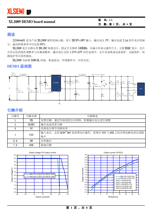
XL2009 DEMO board manual版 页本:1.1 数:第 1 页, 共 6 页描述221044A01 是为产品 XL2009 制作的演示板,用于 DC8V~36V 输入,输出电压 5V,输出电流 2.1A 的车充应用演 示,最高转换效率可以达到 93%。
XL2009 是开关降压型 DC-DC 转换芯片;固定开关频率 180KHz,可减小外部元器件尺寸,方便 EMC 设计。
芯片 具有出色的线性调整率与负载调整率,输出电压支持 1.25V~32V 间任意调节。
芯片内部集成过流保护、过温保护、短 路保护等可靠性模块。
XL2009 为标准 SOP-8L 封装,集成度高,外围器件少,应用灵活。
DEMO 原理图引脚介绍引脚号 1 2 3 4 5,6 7,8 引脚名称 FB OCSET VC VIN SW GND 输出电流设置引脚 内部电压调节旁路电容 输入电压,支持 DC8V~36V 宽范围电压操作,需要在 VIN 与 GND 之间并联电解电容以消除 噪声 功率输出 接地引脚Output current VS RCS3.0 2.8 2.64.5 4.0引脚描述 反馈引脚,通过外部电阻分压网络,检测输出电压进行调整Output voltage VS Output current5.5 5.02.4 2.2 2.0 1.8 1.6 1.4 1.2 1.0 0.8 0.6 0.4 0.2 0.00.0 0.5 1.0 1.5 2.0 2.5 3.0Output voltage(V)3.5 3.0 2.5 2.0 1.5 1.0 0.5 0.0VIN=12V,VOUT=5V,RCS=14K VIN=24V,VOUT=5V,RCS=14KOutput current(A)VIN=12V,VOUT=5V VIN=24V,VOUT=5V IOUT=1.0A,RCS=5K IOUT=1.5A,RCS=8K IOUT=1.8A,RCS=11K IOUT=2.1A,RCS=14K IOUT=2.5A,RCS=16K0246810121416Output current(A)RCS(Kohm)第 1 页 ,共 6 页XL2009 DEMO board manual版 页本:1.1 数:第 2 页, 共 6 页物料清单序号 1 2 3 4 5 6 7 8 9 10 11 12 13 14 15 16 17 18 19 20 数量 3 1 2 1 2 1 1 1 1 1 1 1 1 1 1 2 1 1 1 1 参考位号 C1,C2,CC C3 CINA,CINB COUT D1A,D1B DZ FUSE L1 L2 LED R1 R2 R3 R4 R5 R6,R8 R7 RCS U1 USB 说明 1uF,50V,Ceramic,X7R,0805 33pF,50V,Ceramic,CH,0603 47uF,50V,Electrolytic,(6.3*11) 220uF,16V,Electrolytic,(6.3*11) 40V,3A,SMA,Schottky Barrier Rectifier 6.2V,500mW,ZENER,MINI MELF 2A,63V,High Inrush,1206 47uH,3A,(10*4) 100uH,2A(8*10) Blue,0805,SMD 3.3KΩ,1%,1/16W,Thick Film,0603 10KΩ,1%,1/16W,Thick Film,0603 1KΩ,1%,1/16W,Thick Film,0603 33Ω,1%,1/4W,Thick Film,1206 75KΩ,1%,1/16W,Thick Film,0603 49.9KΩ,1%,1/16W,Thick Film,0603 43.2KΩ,1%,1/16W,Thick Film,0603 14KΩ,1%,1/16W,Thick Film,0603 36V,3A,BUCK,DC-DC Converter,SOP-8L DIP RC0603XR-073301 RC0603XR-071002 RC0603XR-071001 RC1206XR-070330 RC0603XR-077502 RC0603XR-074992 RC0603XR-074322 RC0603XR-071402 XL2009 Yageo Yageo Yageo Yageo Yageo Yageo Yageo Yageo XLSEMI 生产商型号 C2012X7R1H105K C1608CH1H330J YXA-50V-47uF YXA-16V-220uF SS34 ZMM55C6V2 F1206HI2000V063T 生产商 TDK TDK Rubycon Rubycon Fairchild ICM AEM性能数据VIN=8V VIN(V) 8.036 8.033 8.024 8.015 8.006 7.997 7.988 7.979 7.969 7.960 7.951 7.941 8.049 8.039 IIN(A) 0.073 0.139 0.204 0.271 0.339 0.407 0.476 0.546 0.616 0.687 0.759 0.832 0.892 0.965 VOUT(V) 5.039 5.039 5.038 5.038 5.038 5.038 5.038 5.038 5.038 5.038 5.038 5.038 5.038 5.038 IOUT(A) 0.1 0.2 0.3 0.4 0.5 0.6 0.7 0.8 0.9 1.0 1.1 1.2 1.3 1.4 EFF(%) 85.90 90.26 92.33 92.78 92.81 92.87 92.75 92.51 92.37 92.13 91.83 91.50 91.22 90.92 VIN(V) 12.043 12.031 12.018 12.006 11.994 11.981 11.969 12.018 12.006 11.995 11.983 11.970 11.958 12.047 IIN(A) 0.052 0.097 0.141 0.186 0.232 0.277 0.324 0.368 0.415 0.462 0.510 0.557 0.606 0.649 VIN=12V VOUT(V) 5.045 5.043 5.042 5.042 5.042 5.042 5.042 5.042 5.042 5.042 5.042 5.042 5.042 5.043 IOUT(A) 0.1 0.2 0.3 0.4 0.5 0.6 0.7 0.8 0.9 1.0 1.1 1.2 1.3 1.4 EFF(%) 80.56 86.43 89.26 90.31 90.60 91.16 91.01 91.20 91.07 90.98 90.75 90.75 90.45 90.30第 2 页 ,共 6 页XL2009 DEMO board manual8.029 8.019 8.009 7.984 7.974 7.963 7.957 8.021 8.010 8.000 VIN(V) 24.08 24.08 24.07 24.07 24.06 24.06 24.05 24.06 24.04 24.03 24.03 24.02 24.01 24.01 24.00 23.99 23.98 23.98 23.98 23.97 23.97 23.96 24.06 24.05 1.040 1.114 1.190 1.269 1.346 1.425 1.504 1.570 1.652 1.733 IIN(A) 0.030 0.054 0.076 0.099 0.122 0.145 0.168 0.192 0.215 0.239 0.262 0.286 0.310 0.334 0.358 0.382 0.406 0.431 0.455 0.480 0.504 0.527 0.552 0.577 5.038 5.039 5.038 5.039 5.040 5.040 5.040 5.041 5.042 5.041 VIN=24V VOUT(V) 5.051 5.051 5.050 5.050 5.050 5.050 5.050 5.050 5.050 5.050 5.050 5.051 5.051 5.051 5.051 5.051 5.051 5.052 5.053 5.053 5.053 5.054 5.054 5.054 IOUT(A) 0.1 0.2 0.3 0.4 0.5 0.6 0.7 0.8 0.9 1.0 1.1 1.2 1.3 1.4 1.5 1.6 1.7 1.8 1.9 2.0 2.1 2.2 2.3 2.4 EFF(%) 69.92 77.69 82.82 84.77 86.02 86.85 87.49 87.45 87.93 87.93 88.23 88.23 88.22 88.18 88.18 88.19 88.20 87.99 87.99 87.84 87.84 88.06 87.52 87.41 VIN(V) 36.07 36.06 36.05 36.05 36.05 36.05 36.04 36.04 36.04 36.03 36.03 36.02 36.02 36.02 36.02 35.99 35.99 35.98 35.98 35.97 35.97 35.97 35.97 35.96 1.5 1.6 1.7 1.8 1.9 2.0 2.1 2.2 2.3 2.4 90.50 90.25 89.86 89.52 89.22 88.83 88.44 88.07 87.64 87.26 12.028 12.016 12.003 11.991 11.978 11.967 11.955 12.027 12.014 12.001版 页 0.698 0.747 0.796 0.846 0.896 0.947 0.997 1.041 1.093 1.144 IIN(A) 0.023 0.039 0.055 0.070 0.086 0.102 0.118 0.133 0.149 0.165 0.181 0.198 0.213 0.230 0.246 0.262 0.279 0.296 0.312 0.329 0.345 0.362 0.379 0.396本:1.1 数:第 3 页, 共 6 页 5.042 5.043 5.043 5.043 5.044 5.044 5.043 5.043 5.044 5.044 VIN=36V VOUT(V) 5.059 5.059 5.058 5.058 5.058 5.059 5.059 5.059 5.06 5.06 5.06 5.06 5.061 5.062 5.062 5.063 5.065 5.064 5.065 5.066 5.066 5.067 5.068 5.067 IOUT(A) 0.1 0.2 0.3 0.4 0.5 0.6 0.7 0.8 0.9 1.0 1.1 1.2 1.3 1.4 1.5 1.6 1.7 1.8 1.9 2.0 2.1 2.2 2.3 2.4 EFF(%) 60.98 71.95 76.53 80.17 81.57 82.55 83.27 84.43 84.81 85.11 85.35 85.14 85.75 85.54 85.69 85.91 85.75 85.59 85.73 85.62 85.73 85.61 85.50 85.40 1.5 1.6 1.7 1.8 1.9 2.0 2.1 2.2 2.3 2.4 90.08 89.89 89.73 89.48 89.30 89.02 88.85 88.61 88.35 88.17第 3 页 ,共 6 页XL2009 DEMO board manual转换效率:Efficiency VS Load current100 95 90 855.2 5.3版 页本:1.1 数:第 4 页, 共 6 页线性调整率和负载调整率:Output voltage VS Output current75 70 65 60 55 50 45 40 0.0 0.2 0.4 0.6 0.8 1.0 1.2 1.4 1.6 1.8 2.0 2.2 2.4Vin=8V,Vout=5V Vin=12V,Vout=5V Vin=24V,Vout=5V Vin=36V,Vout=5VOutput voltage(V)805.1Efficiency(%)5.04.94.8VIN=8V,VOUT=5V,IOUT=0.1A~2.4A VIN=12V,VOUT=5V,IOUT=0.1A~2.4A VIN=24V,VOUT=5V,IOUT=0.1A~2.4A VIN=36V,VOUT=5V,IOUT=0.1A~2.4A4.7 0.0 0.2 0.4 0.6 0.8 1.0 1.2 1.4 1.6 1.8 2.0 2.2 2.4Load current(A)Output current(A)DEMO 实物图PCB 布局13mm21mm25mm 50mm 顶层21mm第 4 页 ,共 6 页XL2009 DEMO board manual版 页本:1.1 数:第 5 页, 共 6 页底层应用信息输入电容选择 在连续模式中,转换器的输入电流是一组占空比约为 VOUT/VIN 的方波。
2009年DC驱动产品目录说明书
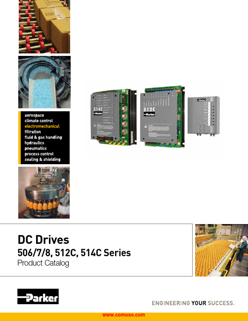
Table of Contents! WARNING - USER RESPONSIBILITYFAILURE OR IMPROPER SELECTION OR IMPROPER USE OF THE PRODUCTS DESCRIBED HEREIN OR RELATED ITEMS CAN CAUSE DEATH, PERSONAL INJURY AND PROPERTY DAMAGE.This document and other information from Parker Hannifin Corporation, its subsidiaries and authorized distributors provide product or system options for further investigation by users having technical expertise.The user, through its own analysis and testing, is solely responsible for making the final selection of the system and components and assuring that all performance, endurance, maintenance, safety and warning requirements of the application are met. The user must analyze all aspects of the application, follow applicable industry standards, and follow the information concerning the product in the current product catalog and in any other materials provided from Parker or its subsidiaries or authorized distributors.To the extent that Parker or its subsidiaries or authorized distributors provide component or system options based upon data or specifications provided by the user, the user is responsible for determining that such data and specifications are suitable and sufficient for all applications and reasonably foreseeable uses of the components or systems.OFFER OF SALEThe items described in this document are hereby offered for sale by Parker Hannifin Corporation, its subsidiaries or its authorized distributors. This offer and its acceptance by the provisions stated in the detailed ‘Offer of Sale’ which is available upon request.Global PartnershipsGlobal SupportParker is committed to helping makeour customers more productiveand more profitable through ourglobal offering of motion andcontrol products and systems. Inan increasingly competitive globaleconomy, we seek to developcustomer relationships as technologypartnerships. Working closely withour customers, we can ensure the bestselection of technologies to suit theneeds of our customers’ applications.Electromechanical Technologiesfor High Dynamic Performanceand Precision MotionParker electromechanicaltechnologies form an importantpart of Parker’s global motion andcontrol offering. Electromechanicalsystems combine high performancespeed and position control with theflexibility to adapt the systems tothe rapidly changing needs of theindustries we serve.Parker HannifinThe global leader in motion and control technologies and systemsWith annual sales exceeding$12 billion in fiscal year 2011,Parker Hannifin is the world’sleading diversified manufacturer ofmotion and control technologiesand systems, providing precision-engineered solutions for a widevariety of mobile, industrial andaerospace markets. The companyemploys approximately 58,000people in 47 countries aroundthe world. Parker has increasedits annual dividends paid toshareholders for 55 consecutiveyears, among the top five longest-running dividend-increase recordsin the S&P 500 index. For moreinformation, visit the company’s website at , or itsinvestor information site at http://About Parker Hannifin CorporationWith more than 30 years of worldwide application experience, Parker assists its customers in improving productivity and reducing energy consumption with a comprehensive, robust range of DC drives and drive systems. Parker DC drive products are sold, supported and serviced worldwide, with solutions from simple speed control to complex multi-motor coordinated process control. Parker DC drive products are easy to configure and commission, with simple but flexible function block-based configuration tools and connectivity with all major industrial fieldbus networks.Digital DC Drives Maximize Flexibility and Functionality Using the same 32-bit control architecture as our current range of AC drive products, Parker’s range of digital DC drives provides the same high level of functionality - and with it flexibility and performance - as comparable AC drive systems, while simultaneously allowing the user to integrate both AC and DC drive systems in a single machine with the same interface and software.Retrofit Existing Applications with the Latest TechnologyBy retrofitting existing DC motor applications with Parker digital DC drives, the user can avoid the cost of replacing an existing functioning, DC motor with a similar AC drive system, while still enjoying the benefits of a flexible control platform and high performance drive.DC590+ Integrator Series 2 Digital DC DriveThe DC590+ uses an advanced control platform to provide high levels of flexibility and performance for a wide range of applications. Designed for machine integrators, the DC590+ features function block programming, multiple communications and feedback options and support worldwide. Available as non-regenerative or full fourquadrant regenerative. Available from 1-2400A maximum. Fieldbus options include Profibus-DP, CANopen, Modbus RTU, Ethernet and DeviceNet.Typical applications include • Converting machinery • Hoists and cranes• Plastics processing machinery • Wire and cable manufacturing • Automotive test standsProcessSimple2400A35A15ADC Drives Product Range OverviewGlobal DC Drive Solutions to Maximize Flexibility and Increase performanceDRV Package - “Ready to Install” DC DrivesSave design time, panel space and the time and cost of component sourcing and installation with Parker’s unique DRV drive format. DRV drives include all peripheral power components typically required in a DC drive system, integrated in a self-contained package. This packagecontains the additional components within the footprint of the standard drive module and saves significant panel space while reducing complexity and improving the appearance.01010010002000HPSystemsSingle Phase Analog Non-Isolated Converter: 506/507/508Economical, compact torque and speed control of permanent magnet or shunt wound DC motors. Selectable between 110VAC or 230VAC single phase supply. Tachometer or armature voltage feedback, 3, 6, or 12A armature options.Typical applications include:• Conveyors, basic speed control • Packaging machineryDC590+ DRV - “Ready to Install” Series 2The DC590+ DRV Series version is a complete packaged drive solution, including AC line contactor, AC line fuses, DC fuse, control / field fuse and provisions for a motor blower starter. The DRV series reduces panel complexity while saving on panel space. Available to 1750 HP (2400A) maximum.Single Phase Two Quadrant Analog Isolated Converter: 512CThe 512C provides effective torque and speed control of permanent magnet or wound field DC motors. Extremely linear speed and current loops in an isolated package, ideal for single or multiple motor applications up to 32A (10 HP at highest input voltage).Typical applications include:• Centrifugal fans and pumps • Extruders and mixers• Small paper converting machinesSingle Phase Four Quadrant Analog Isolated Converter: 514CThe 514C offers full four quadrant regenerative control of permanent magnet or wound field DC motors. Ideal for applications requiring accurate or rapid deceleration of high inertia loads. Effective for single or multiple motor applications to 32A (10 HP at highest input voltage).Typical applications include:• Machine tool spindles • Wire drawing machines •Winders/Reelers01010010002000 HP1010010002000 HP010*******2000 HP010*******2000 HPAnalog DC Drives RangeDescriptionThe 506, 507 and 508 series drives break new ground in cost-effective DC motor control. Available in 3, 6 or 12A armature ratings, the feature packed minimum footprint design is ideal for speed or torque control of permanent magnet or shunt wound DC motors fed from single phase supplies.Typical applications include:• Fans and pumps • Conveyors• Packaging machineryLow cost high featured design IP20 protected coversCompact footprint and DIN rail mounting Selectable 110V or 230V supplySelectable tach or armature voltage feedbackStandardsMarkedEN61800-3 (EMC) with external filterEN50178 (safety, low voltage directive)andTechnical SpecificationAnalog DC Drives506/507/508 SeriesUp to 2 HP/12ADimensions (in/mm)Note: Color of enclosure may vary from illustrationDescriptionIsolated control circuitry, a host of features, and extremely linear control loop make the 512C ideal for single motor or multi-drive applications. The 512C is suitable for controlling permanent magnet or field wound DC motors in speed or torque control, and can be used “open loop” with armature voltage feedback, or with DC tach feedback for enhanced regulation and speed range. Chassis mount, IP00 rating. Typical applications include:• Centrifugal fans and pumps • Extruders and mixers • ConveyorsTechnical SpecificationsAnalog DC Drives512C SeriesUp to 32AStandards:Marked EN61800-3 (EMC) with external filterEN50178 (safety, low voltage directive)Common Specifications: 512C and 514C Voltage Ratings:Dimensions (in/mm):DescriptionThe regenerative 514C DC drive offers full four quadrant control of DC motors from single phase supplies. As such it is ideal for applications involving overhauling loads or where rapid and accurate deceleration is required. 514C can be used “open loop” with armature voltage feedback, or with DC tach feedback for enhanced regulation and speed range. Chassis mount, IP00 rating. Typical applications include:• Machine tool spindles • Wire drawing machines • Winders/ReelersTechnical SpecificationAnalog DC Drives514C SeriesUp to 32ANote: Color of front panel may vary from illustrationDrive mounted on a “footprint” filterEMC Filtersfor AC and DC DrivesDescriptionA range of pre-selected EMC (Electromagnetic Compatibil-ity)/RFI (Radio Frequency Interference) Filters are avail-able, suitable for all drives. These filters are a cost effective and easily implemented solution for the abatement of EMC in order to meet certain directives. Installation of the drive must be in accordance with the installation guidelines in the product manual.Filters described as “footprint” type are designed to save panel space by mounting behind the drive.Ordering© 2012 Parker Hannifin Corporation. All rights reserved.Parker Hannifin CorporationSSD Drives Division 9225 Forsyth Park Dr.Charlotte, NC 28273 USATel: (704) 588-3246 Fax: (704) 588-3249AE – UAE, Dubai Tel: +971 4 8127100 ********************AR – Argentina, Buenos Aires Tel: +54 3327 44 4129AT – Austria, Wiener Neustadt Tel: +43 (0)2622 23501-0 *************************AT – Eastern Europe, Wiener NeustadtTel: +43 (0)2622 23501 900 ****************************AU – Australia, Castle Hill Tel: +61 (0)2-9634 7777AZ – Azerbaijan, Baku Tel: +994 50 2233 458****************************BE/LU – Belgium, Nivelles Tel: +32 (0)67 280 900*************************BR – Brazil, Cachoeirinha RS Tel: +55 51 3470 9144BY – Belarus, Minsk Tel: +375 17 209 9399*************************CA – Canada, Milton, Ontario Tel: +1 905 693 3000CH – Switzerland, Etoy Tel: +41 (0)21 821 87 00*****************************CL – Chile, Santiago Tel: +56 2 623 1216CN – China, Shanghai Tel: +86 21 2899 5000CZ – Czech Republic, Klecany Tel: +420 284 083 111*******************************DE – Germany, Kaarst Tel: +49 (0)2131 4016 0*************************DK – Denmark, Ballerup Tel: +45 43 56 04 00*************************ES – Spain, Madrid Tel: +34 902 330 001 ***********************FI – Finland, Vantaa Tel: +358 (0)20 753 2500 *************************FR – France, Contamine s/Arve Tel: +33 (0)4 50 25 80 25 ************************GR – Greece, Athens Tel: +30 210 933 6450 ************************HK – Hong Kong Tel: +852 2428 8008HU – Hungary, Budapest Tel: +36 1 220 4155*************************IE – Ireland, Dublin Tel: +353 (0)1 466 6370 *************************IN – India, MumbaiTel: +91 22 6513 7081-85IT – Italy, Corsico (MI) Tel: +39 02 45 19 21 ***********************JP – Japan, Tokyo Tel: +81 (0)3 6408 3901KR – South Korea, Seoul Tel: +82 2 559 0400KZ – Kazakhstan, Almaty Tel: +7 7272 505 800****************************LV – Latvia, Riga Tel: +371 6 745 2601 ************************MX – Mexico, Apodaca Tel: +52 81 8156 6000MY – Malaysia, Shah Alam Tel: +60 3 7849 0800NL – The Netherlands, OldenzaalTel: +31 (0)541 585 000 ********************NO – Norway, Ski Tel: +47 64 91 10 00************************NZ – New Zealand, Mt Wellington Tel: +64 9 574 1744PL – Poland, Warsaw Tel: +48 (0)22 573 24 00 ************************PT – Portugal, Leca da Palmeira Tel: +351 22 999 7360**************************Parker WorldwideRO – Romania, Bucharest Tel: +40 21 252 1382*************************RU – Russia, Moscow Tel: +7 495 645-2156************************SE – Sweden, Spånga Tel: +46 (0)8 59 79 50 00 ************************SG – Singapore Tel: +65 6887 6300SK – Slovakia, Banská Bystrica Tel: +421 484 162 252**************************SL – Slovenia, Novo Mesto Tel: +386 7 337 6650**************************TH – Thailand, Bangkok Tel: +662 717 8140TR – Turkey, Istanbul Tel: +90 216 4997081 ************************TW – Taiwan, Taipei Tel: +886 2 2298 8987UA – Ukraine, Kiev Tel +380 44 494 2731*************************UK – United Kingdom, WarwickTel: +44 (0)1926 317 878 ********************US – USA, Cleveland Tel: +1 216 896 3000VE – Venezuela, Caracas Tel: +58 212 238 5422ZA – South Africa, Kempton ParkTel: +27 (0)11 961 0700*****************************。
XL2009规格书(官方版)

3A 180KHz 36V Buck DC to DC Converter With CV/CC Loop XL2009Featuresn Wide 8V to 36V Input Voltage Range n Output Adjustable from 1.25V to 32V n Maximum Duty Cycle 100%n Minimum Drop Out 0.3Vn Fixed 180KHz Switching Frequency n Maximum 3A Switching Currentn Internal Optimize Power MOSFETn High e fficiencyn Excellent line and load regulationn With output constant current loopn Built in thermal shutdown functionn Built in current limit functionn Built in output short protection function n Available in SOP8L package Applicationsn Car Chargern Battery Chargern LCD Monitor and LCD TVn Portable instrument power supplyn Telecom / Networking Equipment General DescriptionThe XL2009 is a 180 KHz fixed frequency PWM buck (step-down) DC/DC converter, capable of driving a 2.5A load with high efficiency, low ripple and excellent line and load regulation. Requiring a minimum number of external components, the regulator is simple to use and include internal frequency compensation and a fixed-frequency oscillator.The PWM control circuit is able to adjust the duty ratio linearly from 0 to 100%. An over current protection function is built inside. When short protection function happens, the operation frequency will be reduced from 180KHz to 48KHz. An internal compensation block is built in to minimize external component count.Figure1. Package Type of XL20093A 180KHz 36V Buck DC to DC Converter With CV/CC LoopXL2009Pin ConfigurationsFigure2. Pin Configuration of XL2009 (Top View) Table 1 Pin DescriptionPin Number Pin Name Description1 FB Feedback Pin (FB). Through an external resistor divider network, FB senses the output voltage and regulates it. The feedback threshold voltage is 1.25V.2 OCSET Output Constant Current Set Pin;3 VC Internal V oltage Regulator Bypass Capacity. In typical system application, The VC pin connect a 1uf capacity to VIN.4 VIN Supply V oltage Input Pin. XL2009 operates from a 8V to 36V DC voltage. Bypass Vin to GND with a suitably large capacitor to eliminate noise on the input.5,6 SW Power Switch Output Pin (SW). SW is the switch node that supplies power to the output.7,8 GND Ground Pin. Care must be taken in layout. This pin should be placed outside of the Schottky Diode to output capacitor ground path to prevent switching current spikes from inducing voltage noise into XL2009.3A 180KHz 36V Buck DC to DC Converter With CV/CC Loop XL2009 Function BlockFigure3. Function Block Diagram of XL2009Typical Application CircuitFigure4. XL2009 Typical Application Circuit (VIN=8V~36V, VOUT=5V/2.1A)3A 180KHz 36V Buck DC to DC Converter With CV/CC Loop XL2009 Ordering InformationPart Number Marking ID Lead Free Lead Free Packing TypePackage TemperatureRangeXL2009E1 XL2009E1 2500 Units on Tape & ReelXLSEMI Pb-free products, as designated with “E1” suffix in the par number, are RoHS compliant.Absolute Maximum Ratings(Note1)Parameter Symbol Value Unit Input Voltage Vin -0.3 to 40 V Feedback Pin Voltage V FB-0.3 to Vin V Output Switch Pin Voltage V Output-0.3 to Vin V Power Dissipation P D Internally limited mW Thermal Resistance (SOP8L)(Junction to Ambient, No Heatsink, Free Air)R JA100 ºC/W Operating Junction Temperature T J-40 to 125 ºC Storage Temperature T STG-65 to 150 ºC Lead Temperature (Soldering, 10 sec) T LEAD260 ºC ESD (HBM) >2000 V Note1: Stresses greater than those listed under Maximum Ratings may cause permanent damage to the device. This is a stress rating only and functional operation of the device at these or any other conditions above those indicated in the operation is not implied. Exposure to absolute maximum rating conditions for extended periods may affect reliability.3A 180KHz 36V Buck DC to DC Converter With CV/CC Loop XL2009 XL2009 Electrical CharacteristicsT a = 25℃;unless otherwise specified.Symbol Parameter Test Condition Min. Typ. Max. Unit System parameters test circuit figure4VFB FeedbackV oltageVin = 8V to 36V, V out=5VIload=0.5A to 2.5A1.225 1.25 1.275 VEfficiency ŋVin=12V ,V out=5VIout=2.1A- 89 - %Electrical Characteristics (DC Parameters)Vin = 12V, GND=0V, Vin & GND parallel connect a 100uf/50V capacitor; Iout=500mA, T a = 25℃; the others floating unless otherwise specified.Parameters Symbol Test Condition Min. Typ. Max. Unit Input operation voltage Vin 8 36 V Quiescent Supply Current I q V FB =Vin 2.1 5 mA Oscillator Frequency Fosc 144 180 216 KHz Output Short Frequency Fosp 48 KHz Switch Current Limit I L V FB =0 4 A Max. Duty Cycle D MAX V FB=0V 100 %Output Power PMOS Rdson V FB=0V, Vin=12V,I SW=3A60 80 mohm3A 180KHz 36V Buck DC to DC Converter With CV/CC LoopTypical System Application (VOUT=5V/2.1A)Figure5. XL2009 System Parameters Test Circuit (VIN=8V~36V, VOUT=5V/2.1A)0.00.51.01.52.02.53.03.54.04.55.05.5Output voltage VS Output currentO u t p u t v o l t a g e (V )Output current(A)Figure6. XL2009 System Output Constant Current Curve3A 180KHz 36V Buck DC to DC Converter With CV/CC Loop XL2009404550556065707580859095100Efficiency VS Load currentE f f i c i e n c y (%)Load current(A)Figure7. XL2009 System Efficiency Curve0.00.20.40.60.81.01.21.41.61.82.02.22.42.62.83.0Output current VS RCSO u t p u t c u r r e n t (A )RCS(Kohm)Figure8. RCS VS Output Current Select Curve3A 180KHz 36V Buck DC to DC Converter With CV/CC Loop XL2009 Schottky Diode Selection TableCurrent SurfaceMount ThroughHoleVR (The same as system maximum input voltage)20V 30V 40V 50V 60V1A √1N5817 1N5818 1N5819√1N5820 1N5821 1N5822√MBR320 MBR330 MBR340 MBR350 MBR360 √SK32 SK33 SK34 SK35 SK36√30WQ03 30WQ04 30WQ05√31DQ03 31DQ04 31DQ053A√SR302 SR303 SR304 SR305 SR3063A 180KHz 36V Buck DC to DC Converter With CV/CC Loop XL2009Package InformationSOP8 Package Mechanical Dimensions3A 180KHz 36V Buck DC to DC Converter With CV/CC Loop XL2009Featuresn Wide 8V to 36V Input Voltage Range n Output Adjustable from 1.25V to 32V n Maximum Duty Cycle 100%n Minimum Drop Out 0.3Vn Fixed 180KHz Switching Frequency n Maximum 3A Switching Currentn Internal Optimize Power MOSFETn High e fficiencyn Excellent line and load regulationn With output constant current loopn Built in thermal shutdown functionn Built in current limit functionn Built in output short protection function n Available in SOP8L package Applicationsn Car Chargern Battery Chargern LCD Monitor and LCD TVn Portable instrument power supplyn Telecom / Networking Equipment General DescriptionThe XL2009 is a 180 KHz fixed frequency PWM buck (step-down) DC/DC converter, capable of driving a 2.5A load with high efficiency, low ripple and excellent line and load regulation. Requiring a minimum number of external components, the regulator is simple to use and include internal frequency compensation and a fixed-frequency oscillator.The PWM control circuit is able to adjust the duty ratio linearly from 0 to 100%. An over current protection function is built inside. When short protection function happens, the operation frequency will be reduced from 180KHz to 48KHz. An internal compensation block is built in to minimize external component count.。
ElcomSoft产品目录2009 - ELCOMSOFT
ELCOMSOFT产品目录2009密码确认与密码恢复成立于1990年,ElcomSoft有限公司(以下简称为称为ElcomSoft)是一家私有软件公司, 总部在于俄罗斯, 莫斯科。
ElcomSoft专门为创造密码恢复工具.密码保护机密文件,正在成为越来越一天的重要组成部分,对企业及最终用户一天的生活很重要组成部分是用密码保护机密文件。
丢失密码或没有忘记密码的恢复手段就干扰办公室工作流程及造成严重损害.Elcomsoft公司的获奖的密码恢复软件采用强大的算法正在不断增强,使企业和最终用户继续使用他们的贵重数据. ElcomSoft是微软金牌认证合作伙伴以及英特尔软件合作伙伴计划成员,俄罗斯密码学协会成员,计算机安全协会成员,以及共享软件联盟终身会员.lcomSoft是值得引以自豪。
我们努力改善现有的产品,同时研究和开发新的和令人兴奋的。
我们对查询及所有的跟任何软件有关的问题提供专业的,有益的,反应迅速的答复.商业与政府登记:ElcomSoft邓白氏邓氏编码(D&B D-U-N-S®)编码:534889845北约商业和政府实体(NCAGE,也CAGE)编码:SCM11中央承包商登记处(CCR):请访问, 进入我们的NCAGE或DUNS编号.Elcomsoft和Elcomsoft标识是ElcomSoft有限公司在美国,俄罗斯和其他国家注册的商标。
Microsoft和Windows也是Microsoft Corporation在美国和/或其他国家注册的商标。
Intel和Intel标识是Intel公司在美国和其他国家注册的商标.Elcomsoft密码恢复软件包Elcomsoft密码恢复工具的完整套件允许企业和政府客户取消受保护的磁盘和系统并解密常用软件保护的档案和文件。
基于内部测试和ElcomSoft宝贵客户的反馈,这些密码恢复工具是市场上最快,最容易使用的和最便宜的工具.创新科技ElcomSoft已开辟了多项创新软件可以更方便地从操作系统, 微软Office产品,Adobe PDF文件,ZIP和RAR压缩文件,以及其他各种应用中恢复遗失的密码。
nVent ERIFLEX 分线盒及接线盒系列说明书
分线盒,接线盒,接线端子摘要nVent ERIFLEX Advanced 技术 ....................................................................................................................................................................3-4单极分线盒(UD系列) ...............................................................................................................................................................................5-16二极和四极分线盒(TD & BD系列) ........................................................................................................................................................17-22接线盒(SB系列) .....................................................................................................................................................................................23-38接线端子(SBTT,SBLL & SBLT 系列) ...................................................................................................................................................39-45四极分线盒&绝缘支撑(TR & BS 系列) ...............................................................................................................................................46-47可继开PEN系统 .........................................................................................................................................................................................48-49间隔器&附件 . (50)DIN标导轨 ..................................................................................................................................................................................................51-52对照表 .........................................................................................................................................................................................................53-552|/ERIFLEX/ERIFLEX | 3接线盒和分线盒nVent ERIFLEX Advanced 技术无�nVent ERIFLEX Advanced 技术是一款高阻抗,低烟,无卤和阻燃材料(LSHFFR ). nVent ERIFLEX 接线盒及分线盒产品在火灾情况下不产生腐蚀性气体,且烟度相对较低。
OFS AccuFLEX 和 AccuRiser 可滚动纤维缆系列产品说明书
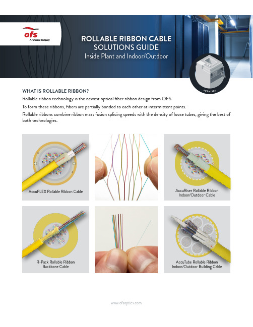
WHAT IS ROLLABLE RIBBON?Rollable ribbon technology is the newest optical fiber ribbon design from OFS.To form these ribbons, fibers are partially bonded to each other at intermittent points.Rollable ribbons combine ribbon mass fusion splicing speeds with the density of loose tubes, giving the best of both technologies.AccuFLEX Rollable Ribbon Cable AccuRiser Rollable Ribbon Indoor/Outdoor Cable R-Pack Rollable Ribbon Backbone Cable AccuTube Rollable Ribbon Indoor/Outdoor Building CableSOLUTIONS GUIDE Inside Plant and Indoor/OutdoorWHY ROLLABLE RIBBON?Maximizes Duct Utilization Smaller, Lighter Weight Enables Mass Fusion Splicing Easily Rolled and Routed Reduces Prep TimeCABLE TRAY/LADDER RACK APPLICATIONS - 12x8”More Fibers per Tray72-Fiber Rollable Ribbon Cable72-Fiber Flat Ribbon Cable 72-Fiber Tight Buffered Cable Increased density improves data center space efficiencyDifferent designs for different applications• Rollable ribbons are easily spliced with common ribbon splicing equipment • Uses standard ribbon protection sleeves • Significant productivity improvement versus single fiber splicing • Easier prep due to gel-free construction •Loss is similar to flat ribbon splicing or other fixed V-Groove splicer results FIBERS SPLICED PER DAYRollable Ribbon F I B E R S S P L I C E D P E RD A Y120010008006004002000SPLICING ROLLABLE RIBBONSFurukawa S326R High Precision CleaverFurukawa S218R-200 Thermal Fiber Stripper Furukawa S124M12 Mass Fusion SplicerROLLABLE RIBBON CABLESOLUTIONS GUIDE Inside Plant and Indoor/OutdoorACCURISER ROLLABLE RIBBON CABLE Versatile Indoor/Outdoor Cable Available in Very High Fiber Counts; Crush Resistant and Very FlexibleClassic Indoor Cable for Versatile Deployments within Buildings R-PACK ROLLABLE RIBBON BACKBONE CABLE Compact, Lightweight Cable Rated for Horizontal Backbone ApplicationsHIGHLIGHTS•Versatile cable for indoor and outdoor environments •Can run from handhole to distribution frame, eliminating splicing between outdoor and indoor cables •Crush resistant and flexible •Max fiber count 864 – AccuRiser 96-864, AccuTube RR I/O 1728• Dual rated Low Smoke/Zero Halogen–UL 1666 and CPR rated ≥ Euroclass CcaHIGHLIGHTS••• HIGHLIGHTS•Backbone distribution cable •Available in either OFNP or a Dual Rated LSZH Jacket •Route in backbone applications like ladder racking •Plenum available in 12-72 Fiber; Dual Rated Riser/LSZH available in 12-144 Fiber •CPR Rated ≥ Euroclass Cca • Indoor/outdoor rated for short runs, building to building or first handholeACCUTUBE ROLLABLE RIBBON CABLE Indoor/Outdoor Building Cable - 1728 Fibers OnlyCPR Rated: Euroclass B2caSOLUTIONS GUIDE Inside Plant and Indoor/OutdoorAvailable Vertical Spaces Raceways Plenum (Indoor Only)Riser CPR R-Pack Backbone RRAccuFlex RRAccuRiser RRAccuTube I/O RR BuildingR-PackAccuTube。
- 1、下载文档前请自行甄别文档内容的完整性,平台不提供额外的编辑、内容补充、找答案等附加服务。
- 2、"仅部分预览"的文档,不可在线预览部分如存在完整性等问题,可反馈申请退款(可完整预览的文档不适用该条件!)。
- 3、如文档侵犯您的权益,请联系客服反馈,我们会尽快为您处理(人工客服工作时间:9:00-18:30)。
主要用途: 软件控制指向性优化场馆覆盖,提高直达声与混响声的比例,
改善语言清晰度
极佳的语言清晰度和音乐
网络控
产品互通互联独特的数字滤波器功能与低延时使用强大的多通道转换法则用于
1kHz时声束清晰
很明显,在3kHz侧瓣非常强,主声束很清晰,这样会导致许多实际声学问题,不仅仅发生在混响空间内。
频率高到6kHz时,出现多个侧瓣,无法有效控制声束。
在12kHz时,同轴音箱指向特性要比传统音箱更宽。
1kHz的声束清晰
3kHz时声束清晰
6kHz时声束清晰,QFLEX频率范围要比同轴的宽的多即使在12kHz时,只有轻微干涉,侧瓣比主声束增益小
声束控制部件特性
低频率
低频和高频单元根据用途专门设计。
08
限制提供驱动器电流,保证驱动器温度在安全限制以内,同时最大化声压级
所有的措施都是保证产品能尽可能正常工作,如果出现意外情况则酌情进行必要的保护,直到暂时停机
8通道单元(QFLEX8)16通道单元 (QFLEX16)
远距离声压级要求
有效低音控制BeamEngine QFLEX
使用软件选择所需型号
支架可以装在箱体一侧
如有特殊安装需要,我们也可以提供设计上的支持。
QFlex VNET 均衡与延时设置参数设置窗口
参数控制与感应记录窗口
调整声束覆盖。
