Wonderware 培训资料教学文案
wonderware ide 培训的手册文档第一章
Lab 1 –Creating the GalaxyIntroductionIn this lab, you will create the Galaxy and connect to it using the ArchestrA IDE. This Galaxy will be used during the class to develop the sample application.ObjectivesUpon completion of this lab, you will be able to:Create a GalaxyConnect to a Galaxy using the ArchestrA IDECreate the GalaxyIn the following steps, you will create a Galaxy and connect to it.1.Open the ArchestrA IDE(Start | All Programs | Wonderware | ArchestrA IDE).The Connect To Galaxy dialog box appears with the local node name displayed in the GR node name drop-down list.In this image, TRAININGPC-ENG2is the local computer name.2.Click the New Galaxy button to create a new Galaxy.The New Galaxy dialog box appears.3.In the Galaxy name field, enter TrainingGalaxy.4.In the Galaxy type field, confirm Base_Application_Server.cab is selected.5.Click Create.The Create Galaxy dialog box appears and shows the Galaxy creation progress. This will take a few moments. Check to make sure that no error messages are displayed.6.When the Create Galaxy progress displays 100% completed, click Close.The newly created TrainingGalaxy now appears in the Galaxy name drop-down list.7.Click Connect.The Connect To Galaxy dialog box closes and, after a few seconds, the ArchestrA IDE opens.You will use the ArchestrA IDE to develop the Galaxy throughout the remainder of this class.-This page intentionally left blank -。
最新wonderware培训资料

最新wonderware培训资料最新 Wonderware 培训资料Wonderware 作为一款在工业自动化领域广泛应用的软件,其功能强大、应用广泛。
为了帮助大家更好地掌握和运用 Wonderware,我们精心准备了这份最新的培训资料。
Wonderware 软件涵盖了多个方面的功能,包括但不限于数据采集与监控、过程控制、人机界面设计等。
对于初学者来说,可能会感到有些复杂和无从下手。
但别担心,我们会逐步为您揭开它的神秘面纱。
首先,让我们来了解一下 Wonderware 的历史和背景。
Wonderware成立于_____年,多年来一直致力于为工业领域提供先进的自动化解决方案。
它在全球范围内得到了广泛的应用,涵盖了制造业、能源、水处理等多个行业。
Wonderware 软件的安装和配置是使用它的第一步。
在安装过程中,需要注意系统的兼容性以及相关的驱动程序的安装。
配置方面,包括网络设置、数据库连接等,这些都需要根据实际的应用场景进行仔细的调整和设置。
接下来是数据采集与监控功能。
Wonderware 能够实时采集各种设备和传感器的数据,并将其以直观的方式展示给用户。
通过配置数据点、建立通信协议等操作,可以实现对生产过程中的各种参数的实时监测。
比如温度、压力、流量等关键参数,一旦出现异常,系统能够及时发出警报,以便操作人员采取相应的措施。
在过程控制方面,Wonderware 提供了丰富的控制策略和算法。
用户可以根据实际的工艺流程,编写控制逻辑,实现对生产过程的精确控制。
这不仅提高了生产效率,还保证了产品的质量和稳定性。
人机界面设计是 Wonderware 的一大特色。
一个好的人机界面能够提高操作人员的工作效率和舒适度。
在设计人机界面时,要考虑到布局的合理性、颜色的搭配、操作的便捷性等因素。
可以使用图形、图表、动画等元素,让界面更加生动直观。
Wonderware 还支持与其他系统的集成,比如 ERP 系统、MES 系统等。
wonderware培训教学提纲

w o n d e r w a r e培训Wonderware培训Wonderware公司推出旗舰级 InTouch软件,这是第一个基于微软Windows®操作系统的人机界面(HMI)。
Wonderware只能在windows环境下运行,支持32位及64位操作系统,但wonderware公司建议使用32位操作系统因为64位操作系统部是很稳定,系统容易崩溃带来不必要的损失。
Wonderware软件架构:Intouch等可视部分客户端 Active factory分析部分Information Server CAL等第3方认可软件即符合(微软技术标准,工业标准) App Server发布数据三个服务器 Historian历史数据Information Server实时数据DAServer/I/OserverPLC等第三方软件Daserver/ioserver :收到采集命令,采集数据,发广播包,工作完成后,各机从DAseerver堆栈中提取数据。
概念:1.Archestry 只是一个名字2.Application server:应用程序服务器。
类似于I/Osever 客户端(阀门,泵,开关等运行配置,控制配置,run_time部分)3.Galaxy:数据库4.Galaxy Repostistory:配置的指令存储在此可以用这台机器进行开发。
5.GR是装Galaxy数据库的机器一个(工程)网络只能有一个Galaxy。
安装前准备:APPLICATION SERVER 的同时还可以安装I/OserverGR SQLSERVER可单独也可与APPLICATION 一起装。
Historation > 安装SQL server2005数据库需要建立防火墙,需专门一台机器。
Information server >安装SQL server2005数据库需要建立防火墙,需专门一台机器。
步骤1:1.每台机器装BOOTSTAP(需要主动对GR访问取数据的必须安装不是主动对GR 访问被动的接收数据的不用安装)。
wonderware-ide-培训的手册文档第一章

实验 1 –创建银河介绍在本实验中,您将创建银河,并使用 ArchestrA IDE 连接到它。
此银河将在类期间用于开发示例应用程序。
目标完成本实验后,您将能够:创建银河使用 ArchestrA IDE连接到加尔斧西创建银河在以下步骤中,您将创建一个银河并连接到它。
1.打开ArchestrA IDE(开始 |所有计划 |奇迹软件 |阿尔切斯特拉 IDE)"连接到银河"对话框显示,本地节点名称显示在GR 节点名称下拉列表中。
在此映像中,训练PC-ENG2是本地计算机名称。
2.单击"新建银河"按钮创建新的银河。
将出现"新建银河"对话框。
3.在"银河"名称字段中,输入训练银河。
4.在"银河类型"字段中,确认已选择"基础_应用程序_服务器.cab"。
5.单击"创建"。
将显示"创建银河"对话框并显示"银河"创建进度。
这将需要一些时间。
检查以确保未显示任何错误消息。
6.当创建银河进度显示100% 已完成时,单击"关闭"。
新创建的训练银河现在显示在Galaxy 名称下拉列表中。
7.单击"连接"。
"连接到银河"对话框将关闭,几秒钟后,ArchestrA IDE 将打开。
您将使用ArchestrA IDE 在本课程的其余部分中开发银河。
- 此页有意留空 -。
wonderware ide 培训的手册文档第7章,共21章

Lab 7 –Configuring Change Control and PropagationIntroductionIn this lab, using the derivation hierarchy, you will control the changes made to derived objects by locking attributes. Additionally, you will use this feature to propagate the changes from templates to existing derived objects. This helps to establish standards in the Galaxy.ObjectivesUpon completion of this lab, you will be able to:Control changes to derived objects by locking attributesPropagate changes from templates to derived objectsLock the Attributes in $TankIn the following steps, you will lock attributes, which prevent changes to those attributes on derived objects. You will then observe that the changes have been propagated down the derivation hierarchy.1.Click on the Derivation tab to display the Derivation view.The derivation from the $UserDefined template to the Mixer_001instance is displayed.2.Double-click the $Tank template to display the configuration editor and ensure LT.PV is selected.3.In the Description field, enter Tank Level value.4.In the Engineering units field, change the value from Gallons to Liters.5.For both the Description and Engineering units attributes,click the lock icon.6.Expand the Enable I/O scaling area by clicking on the down arrow button.7.Next to the Scaling group, click the lock icon.This locks all of the attributes in this group.8.Click the lock icons to unlock the following attributes:EU value: MaximumEU range value: MaximumThis enables you to use this template for a variety of derived tanks where the maximum attributes differ depending on the tank type. These attributes can then be customized when derived objects are created.9.In the Field attributes list, click TT.PV.10.In the Description field,enter Tank Temperature value and lock the attribute.11.In the Engineering units field, change the value to Celsius and lock the attribute.12.In the Enable I/O scaling area, lock all of the attributes except for the maximum attributes, as donebefore, for the LT.PV field attribute.13.Save and close the configuration editor.14.In the Check In dialog box,Comment field,enter Locking attributes and click OK.The Check In dialog box appears.Notice the messages display that the $Mixer derived template and the Mixer_001instance were updated, because they are derived from the $Tank template.15.Click Close.In the Derivation view, notice the icon next to the Mixer_001instance showing that it requires redeployment for the changes to take effect. You will redeploy this instance later.Verify the Propagation to an InstanceNext, you will verify that the changes you made in the previous steps have propagated to the instance.16.Double-click on the Mixer_001instance to open the configuration editor.17.In the Inherited field attributes list, click on LT.PV and expand the Enable I/O scaling area.The previously locked attributes are now grayed out and cannot be changed, but the unlocked attributes can still be changed.18.Click on TT.PV to view that the same configuration applies to the locked and unlocked attributes.19.Click on the Close button to close the configuration editor.Lock the Attributes in $MixerNext, you will lock some of the attributes within the mixer template.20.Double-click the $Mixer template to open the configuration editor.21.In the Field attributes list, ensure TP1.Cmd is selected.22.In the Description field, enter Command to start/stop Transfer Pump1and lock the attribute.23.In the following field attributes, type the following descriptions and lock the attributes:All of the field attributes are now configured.24.In the Inherited field attributes area, click on LT.PV and expand the Enable I/O scaling group.25.Lock the Scaling Maximum values.26.Click on TT.PV and change the following attributes:EU value: Maximum450.0and lockedEU range value: Maximum455.0and locked27.Save and close the configuration editor.28.In the Comment field, enter Locking attributes and click OK.The Check In dialog box appears.Notice that the changes have propagated down the hierarchy structure to the Mixer_001instance.29.Click Close.Verify PropagationNext, you will verify that the changes have propagated to the instance.30.Open the Mixer_001configuration editor.31.In the Inherited field attributes list, click on each of the TP1.Cmd,TP1.PV,TP2.Cmd, and TP2.PVattributes to confirm that the descriptions are locked and cannot be edited.32.Click on the LT.PV and TT.PV attributes and expand the Enable I/O scaling group to confirm that thescaling maximum attributes have been locked.33.Close the configuration editor.Redeploy the Mixer InstanceNow, you will redeploy the instance to runtime.34.Right-click Mixer_001and select Deploy.35.Keep the default options and click OK.36.When the progress shows 100% completed, click Close.-This page intentionally left blank -。
wonderware ide 培训的手册文档第16章,共21章
Lab 16 –Configuring HistoryIntroductionIn this lab, you will configure the Galaxy for historization to the local Historian Server. Specifically, you will configure the $gAppEngine object to store historical data.Additionally, you will configure the object attributes to be historized.ObjectivesUpon completion of this lab, you will be able to:Configure a $gAppEngine object to store historical data to a Historian ServerConfigure objects to enable history including a History extensionConfigure Objects for HistoryIn the following steps, you will configure multiple objects in the Galaxy to begin historizing data.1.In the Deployment view, double-click AOSPlatform1to open the configuration editor.2.On the General tab, in the History store forward directory field, enter C:\S&F.3.Save and close the configuration editor.4.In the Check In dialog box, Comment field, enter Store and Forward configuration and click OK.5.Double-click AppEngine1to open the configuration editor.6.On the General tab, check the Enable storage to historian check box.7.In the Historian field, enter [your instructor will confirm the computer name]. In this image,TrainingPC-ENG2will be used.8.Save and close the configuration editor.9.In the Check In dialog box,Comment field, enter Historian configuration and click OK.10.In the Template Toolbox,Working toolset, double-click $Mixer to open the configuration editor.11.In the Inherited field attributes list, select LT.PV and check the Enable history check box.12.In the Trend high field, enter 100.0and lock the history group.13.Save and close the configuration editor.14.In the Check In dialog box,Comment field, enter LT historization and click OK.15.When the Check In progress shows Object 1 of 1 completed, click Close.16.In the Template Toolbox,Working toolset, double-click Inlet1to open the configuration editor.17.Check the Historize PV check box and lock the PV group.18.Save and close the configuration editor.19.In the Check In dialog box,Comment field, enter PV historization and click OK.20.When the Check In progress shows Object 1 of 1 completed, click Close.21.In the Template Toolbox,Working toolset, double-click Agitator to open the configuration editor.22.On the Extensions tab, Extendable Attributes list, select Speed.23.Configure the Speed attribute as follows:History extension checked and lockedEngineering units:RPMTrend high:50Description:Agitator Speed24.Save and close the configuration editor.25.In the Check In dialog box,Comment field, enter Speed historization and click OK.26.When the Check In progress shows Object 1 of 1 completed, click Close.The Deployment view now displays several objects that need to be redeployed.27.Deploy AOSPlatform1and keep the default options.28.When the Deploy progress displays 100% completed, click Close.View the Historical Data with Historian ClientNow, you will use Wonderware Historian Client Trend to view a trend of the historical data.29.Start Wonderware Historian Client Trend (Start | All Programs | Wonderware | Historian Client |Trend).The Server List Configuration dialog box appears.30.In the Server field, enter [check with your instructor]. In this image, TrainingPC-ENG2will be used.31.Check the Use Integrated security check box and click Add.After a few moments, the computer name appears in the Server list.32.Click Close.The Wonderware Historian Client Trend window opens and in the Tag Picker pane, all of the tags configured for historization are displayed.33.Double-click the Agitator_001.Speed tag to add it to the trend chart.The Agitator_001.Speed historical data now displays in the trend chart.You can also drag and drop tags to the trend chart to add them.34.Drag and drop Inlet1_001.PV and M1XX.LT.PV onto the trend chart.Your trend chart will now display all three tags at the same time.35.On the toolbar, click the Enable or disable live or replay mode button.The trend chart now updates automatically.36.Close the Trend application.The Wonderware Historian Client dialog box appears.37.Click No .。
wonderware ide 培训的手册文档第20章,共21章
Lab 20 –Configuring RedundancyIntroductionIn this lab, you will configure a second network connection in Windows for use as the Redundancy Message Channel. Then, you will configure the Galaxy platforms and engines for redundancy. Finally, you will create the hosting relationship, deploy the changes, and force a failover to confirm the functionality.ObjectivesUpon completion of this lab, you will be able to:Configure a secondary network connection in Windows as the Redundancy Message Channel Configure WinPlatform and AppEngine objects for redundancyCreate a deployment model for redundant enginesForce a failover on a redundant systemConfigure Windows for RedundancyIn the following steps, you will configure a second network connection in Windows as the Redundancy Message Channel (RMC). This will need to be done on both computers, where the first is the computer where GRPlatform is deployed and the second is the computer where AOSPlatform1is deployed.1.Connect to the machine where the GRPlatform is installed [for the remote computer, this will be themachine where the AOSPlatform1in installed].2.Open Network Connections(Start | Control Panel | Network and Sharing Center).3.Click Change adapter settings.The Network Connections window appears.4.Right-click Local Area Connection and select Rename.5.Rename the connection ArchestrA.6.Right-click Local Area Connection 2and select Rename.7.Rename the connection RMC.8.Press Alt+N to unhide the Menu bar.9.On the Advanced menu, select Advanced Settings.The Advanced Settings dialog box appears.10.In the Connections area, select ArchestrA and click the Up Arrow button.The ArchestrA connection is now listed first.11.Click OK.12.In the Network Connections window, right-click RMC and select Properties.The RMC Properties dialog box appears.13.In the This connection uses the following items area, select Internet Protocol Version 4(TCP/IPv4).14.Click the Properties button.The Internet Protocol Version 4 (TCP/IPv4) Properties dialog box appears.15.Click the Use the following IP address option.16.In the IP address field, enter 192.168.1.1. [For the remote computer, this will be 192.168.1.2]17.Click in the Subnet mask field to automatically assign the subnet mask.18.In the bottom-right of the window, click the Advanced button.The Advanced TCP/IP Settings dialog box appears.19.On the DNS tab, uncheck the Register this connection’s addresses in DNS check box.20.Click OK.21.In the Internet Protocol Version 4 (TCP/IPv4) Properties dialog box, click OK.22.In the RMC Properties dialog box, click Close.23.Repeat Steps 1to 22on the remote computer where AOSPlatform1is deployed. The IP address thatwill be used on the remote computer will be 192.168.1.2.Configure the Platforms for RedundancyYou will now return to the ArchestrA IDE and configure the platforms for redundancy.24.In the Deployment view, open the GRPlatform configuration editor.25.In the Redundancy area, Redundancy message channel IP address field, enter 192.168.1.1.26.Save and close the configuration editor.27.In the Check In dialog box,Comment field, enter Redundancy configuration and click OK.28.Open the AOSPlatform1configuration editor.29.In the Redundancy group, Redundancy message channel IP address field, enter 192.168.1.2.30.Save and close the configuration editor.31.In the Check In dialog box,Comment field, enter Redundancy configuration and click OK.The Deployment view now displays that both platforms have pending changes.You will redeploy the platforms later in this lab.Configure AppEngine1 for RedundancyYou will now configure AppEngine1for redundancy. Since AppEngine1is currently deployed, you must first undeploy it.32.Right-click AppEngine1and select Undeploy.33.In the Undeploy dialog box, keep the default options and click OK.34.When the Undeploy progress is complete, click Close.35.Open the AppEngine1 configuration editor.36.On the Redundancy tab, check the Enable Redundancy check box.The Redundancy configuration settings auto populate with the default values.37.Keep the defaults and click Save and close.38.In the Check In dialog box,Comment field, enter Redundancy configuration and click OK.The Deployment view now displays the AppEngine1icon with the primary redundant engine icon.39.Expand the Unassigned Host folder to reveal the new backup application engine instance.This was automatically created when redundancy was enabled in AppEngine1.You will now have GRPlatform host the new AppEngine1 (Backup) object.40.Drag and drop AppEngine1 (Backup)onto GRPlatform.Now, you will redeploy the platforms.41.Select both the AOSPlatform1and the GRPlatform.42.Right-click either platform and select Deploy.43.Keep the default options and click OK.44.When the Deploy progress is complete, click Close.45.Return to Object Viewer.Because the platforms redeployed, you will get the following error in Object Viewer.46.Click OK.Object Viewer closes.You will now deploy the application engines using the Include Redundant Partner option.47.In the Deployment view, right-click AppEngine1and select Deploy.48.In the Deploy dialog box, check the Include Redundant Partner check box.49.Click OK.50.When the Deploy progress is complete, click Close.The Deployment view now displays that all objects have been deployed.View the Redundancy Functionality and Data in RuntimeYou will now use Object Viewer and observe selected AppEngine1attributes in the runtime environment. You will then force a failover and observe the changes.51.In the Deployment view, right-click AppEngine1and select View in Object Viewer.52.On the File menu, select Load Watch List.53.Navigate to C:\Training and select MyWatchWindow.54.Click Open.55.Add the following attributes to the watch window:HostRedundancy.IdentityRedundancy.StatusRedundancy.PartnerPlatformRedundancy.PartnerStatusRedundancy.FailoverOccurredRedundancy.ForceFailoverCmdThe watch window displays that AOSPlatform1is currently hosting AppEngine1and the redundancy status is active. Additionally, the GRPlatform is the partner platform and is currently in a Standby mode.56.Save the watch window.You will now force a failover to trigger redundancy and observe the changes.57.In the watch window, double-click AppEngine1.Redundancy.ForceFailoverCmd.The Modify Boolean Value dialog box appears.58.Click the True option and click OK.After a few seconds, the watch window displays GRPlatform as the host platform andAOSPlatform1as the partner platform.You will now refresh Object Viewer to view the changes.59.In the console tree pane, collapse and expand AOSPlatform1and GRPlatform.The pane now displays that AOSPlatform1is no longer hosting any objects and GRPlatform is now hosting all of the objects.60.Click the Mixer1tab.The watch window displays that all attributes are still running and producing good quality data.Lab 20–Configuring Application Redundancy 9-33Application Server 201261.On the Mixer2watch window, observe the same behavior.You will now force another failover to return to the primary redundancy configuration.62.In the Redundancy watch window, double-click AppEngine1.Redundancy.ForceFailoverCmd .63.In the Modify Boolean Value dialog box, click the True option and click OK .After a few seconds, the watch window displays AOSPlatform1as the host platform andGRPlatform as the partner platform.You can also observe what happens when the connection to the remote computer loses connectivity.64.Disable the RMC network connection.After a few seconds, the watch window now displays that the Standby Status isActive –Standbynot Available.9-34Module 9–RedundancyInvensys Learning Services 65.Reenable the RMC connection.After a few seconds, the watch window displays the Standby Statusis back to Active .。
InSQL_Wonderware培训

存储算法: Storage
•
节省大量的存储空间
SwingDoor – 存储策略
9 10 11 12 13 14 8 7 6 17 1 2 3 4 5 18 19 15
16
Value Deadband Swinging Door
Swinging Door
• 动态配置
• 配置导入/导出 • 高可用性功能 • 企业版
IndustrialSQL Server„ 更多 特定功能
• 更加方便地满足政府或行业法规
• 支持Windows 2003
• 客户端应用 - 工厂智能
动态配置
• 当 InSQL运行 时更改标记和对象的配置
– 无需停机或重起 – 对客户端没有影响No interruptions for clients – 没有数据间隔*
数据查询?采用结构化查询语言sql来查询insql数据而不采用专用的查询系统或方式?sql是一个行业的超级标准被行业内广泛采用允许任意的查询能很好地与其它的工厂信息系统集成有上百的现有sql查询工具sql数据读取扩展?数据读取模式?bestfit?counter?cyclic?delta?full?integral?interpolation?maximun?minimum?slope?timeinstate?timeweightedaveragewonderwaresql时序扩展?时间序列的分辨率控制对于时序数据采用基于时基采样的查询避免采用传统行计数的办法?循环增量检索wwretrievalmodecyclicewwretrievalmodedelta?分辨率控制wwresolution1000?基于行的检索wwrowcount100?基于边缘的检索wwedgedetectionleadinganaloghistory日期时间值标记名质量sql数据读取扩展cyclicmodeselectdatetimetagnamevaluequalitydetailfromvanaloghistorywheretagnameinreactlevelandwwretrievalmodecyclicandwwrowcount1000日期时间值标记名质量查询分辨率1秒但它能达到3毫秒
wonderware ide 培训的手册文档第9章
Lab 9 –Creating the MixerIntroductionIn this lab, you will use the valve and motor templates that you created in previous lab to create dedicated templates for each mixer component. You will use these templates and the mixer template to create an object containment, which integrates all of the parts that make up the mixer.You will then update the existing instance by adding instances and configure their attribute references so that their values can be viewed in Object Viewer.Finally, you will create a new instance of the mixer container, which will also create all of the instances of the container and the contained objects.ObjectivesUpon completion of this lab, you will be able to:Create contained templates and a containment relationshipUpdate an existing mixer instanceDeploy contained instancesCreate a new containment instanceCreate the Mixer Containment RelationshipIn the following steps, you will create templates for the parts of the mixer container.1.In the Template Toolbox,Working toolset, right-click $Valve and select New | Derived Template.2.Rename the template $Inlet1.3.Right-click $Valve and select New | Derived Template.4.Rename the template $Inlet2.5.Right-click $Valve and select New | Derived Template.6.Rename the template $Outlet.7.Right-click $Motor and select New | Derived Template.8.Rename the template $Agitator.You will now assign the newly created templates to the mixer template to create a container at the template level.9.Drag and drop the following templates onto the $Mixer template:$Inlet1$Inlet2$Outlet$AgitatorContained templates lose the $at the beginning of their names. If you were to take one or more out of the containment relationship, the $would reappear.Now, you will create instances for all the contained objects that will be added to the existing Mixer_001.10.Display the Model view.11.In the Template Toolbox,Working toolset, right-click Agitator and select New | Instance. Keep thedefault name.12.Create the following instances and keep the default names:The Model view now displays the new instances in the Unassigned Area folder.Configure the Existing Mixer InstanceYou will now create the containment at the instance level.13.In the Model view, assign all four instances in the Unassigned Area folder to the Mixer_001instance.The four contained object instances display configuration warnings, which you will resolve later in this lab.The contained name displays next to an object name in brackets. You will now change the contained name for the new four instances to match the template names.14.In the Model view, right-click Agitator_001and select Rename Contained Name.The Rename Contained Name dialog box appears.15.Rename the contained name Agitator and click OK.The Model view now displays the new contained name for the Agitator_001object.16.Rename the contained names for the following:Inlet1_001change to Inlet1Inlet2_001change to Inlet2Outlet_001change to OutletConfigure I/O for Valves and AgitatorNext, you will configure the attribute references for the newly created contained instances.17.In the Model view, open the Agitator_001configuration editor.18.On the Inputs tab, click the ellipsis button next to the Input Source Reference field.The Galaxy Browser -TrainingGalaxy window appears.19.In the Instances pane, click PLCSim.20.Select the Tagname.M1XX_AG_AuxContact attribute, where XX is your student number. In thisimage, 00will be used.21.Click OK.The Input Source Reference field is now populated with the correct attribute reference.22.In the Outputs tab, click the ellipsis button next to the Output Destination Reference field.23.Select the Tagname.M1XX_AG_CmdStart attribute and click OK.The Output Destination Reference field is now populated with the correct attribute reference.24.Save and close the configuration editor.25.In the Check In dialog box,Comment field,enter I/O references configuration and click OK.26.Open the Inlet1_001configuration editor.27.In the Inputs tab, configure the Input Source Reference as follows:Input 2: CLS Tagname.M1XX_IV1_CLSInput 1: OLS Tagname.M1XX_IV1_OLSThe Input Source Reference fields now display the correct attribute references.28.In the Outputs tab, configure the Output Destination Reference as follows:Output 1: CmdOpen Tagname.M1XX_IV1_CmdOpenThe Output Destination Reference field now displays the correct attribute reference.29.Save and close the configuration editor.30.In the Check In dialog box,Comment field,enter I/O references configuration and click OK.31.Open the Inlet2_001configuration editor.32.In the Inputs tab, configure the Input Source Reference as follows:Input 2: CLS Tagname.M1XX_IV2_CLSInput 1: OLS Tagname.M1XX_IV2_OLSThe Input Source Reference fields now display the correct attribute references.33.In the Outputs tab, configure the Output Destination Reference as follows:Output 1: CmdOpen Tagname.M1XX_IV2_CmdOpenThe Output Destination Reference field now displays the correct attribute reference.34.Save and close the configuration editor.35.In the Check In dialog box,Comment field,enter I/O references configuration and click OK.36.Open the Outlet_001configuration editor.37.In the Inputs tab, configure the Input Source Reference as follows:Input 2: CLS Tagname.M1XX_OV_CLSInput 1: OLS Tagname.M1XX_OV_OLSThe Input Source Reference fields now display the correct attribute references.38.In the Outputs tab, configure the Output Destination Reference as follows:Output 1: CmdOpen Tagname.M1XX_OV_CmdOpenThe Output Destination Reference field now displays the correct attribute reference.39.Save and close the configuration editor.40.In the Check In dialog box,Comment field,enter I/O references configuration and click OK.The Model view no longer displays any exclamation points.Deploy the InstancesEven though Mixer_001is already deployed, the newly contained instances still need to be deployed.41.In the Deployment view, select all four new instances.42.Right-click on any of the highlighted instances and select Deploy.43.Keep the default options and click OK.44.When the Deploy progress displays 100% completed, click Close.View the Mixer Data in RuntimeYou will now return to Object Viewer to observe the attribute values in runtime.45.Right-click on Mixer_001and select View in Object Viewer.Object Viewer appears and is refreshed.Although the container relationship was created and the container deployed, Object Viewer does not display this relationship in the object list.46.In the details pane, add the following attributes to the watch window:The data being displayed is updating in the watch window.47.Save the watch window.Create a New Instance of $MixerNext, you will create a new instance of the mixer template.48.In the ArchestrA IDE,Template Toolbox,Working toolset, right-click $Mixer and select New |Instance.49.In the Model view, under the Unassigned Area folder, expand the Mixer_002instance.Mixer_002has the contained instances of the mixer created with the correct contained names, as well as the mixer instance.The configuration warnings and deployment for these objects will be addressed in a later lab.。
Wonderware 培训资料
Lab 2 – Identifying the Mixer
Course Description and Objectives
Course Description
The System Platform – Part 1 training course is a 4-day instructor-led course designed to give the knowledge necessary to develop and support applications with Wonderware Application Server.
System Platform
Clients
Microsoft Technologies & Industry Standards
Wonderware System Platform
InTouch
(Visualization)
Wonderware Clients
ActiveFactory
(Analysis Client)
?Leverage the .NET Framework for the Automation World
?Object-based application
?One global networked namespace
?Centralized configuration and security
?Multi-user development environment ?Component-based plant application model ?Self documenting
Wonderware 培训资料PPT
▪ Multi-user development environment ▪ Component-based plant application model ▪ Self documenting
• Be able to troubleshoot applications in a standalone and networked environment.
Wonderware System Platform
Project Specific Work
Industry Packs Function Specific Modules
Course Objectives
• Understand the ArchestrA® technology and how it is applicable to the plant floor environment.
• Become familiar with developing objects and instances configuring applications using the Integrated Developing Environment.
ArchestrA
It provides a unified environment for visualization, plant history, device communications and automation application integration.
Application Server’s application, configuration information and project database.
System Platform
最新wonderware培训资料
Wonderware培训Wonderware公司推出旗舰级InTouch软件,这是第一个基于微软Windows®操作系统的人机界面(HMI)。
Wonderware只能在windows环境下运行,支持32位及64位操作系统,但wonderware 公司建议使用32位操作系统因为64位操作系统部是很稳定,系统容易崩溃带来不必要的损失。
Wonderware软件架构:Intouch等可视部分客户端 Active factory分析部分Information Server CAL等第3方认可软件即符合(微软技术标准,工业标准)App Server发布数据三个服务器 Historian历史数据Information Server实时数据DAServer/I/OserverPLC等第三方软件Daserver/ioserver :收到采集命令,采集数据,发广播包,工作完成后,各机从DAseerver 堆栈中提取数据。
概念:1.Archestry 只是一个名字2.Application server:应用程序服务器。
类似于I/Osever 客户端(阀门,泵,开关等运行配置,控制配置,run_time部分)3.Galaxy:数据库4.Galaxy Repostistory:配置的指令存储在此可以用这台机器进行开发。
5.GR是装Galaxy数据库的机器一个(工程)网络只能有一个Galaxy。
安装前准备:APPLICATION SERVER 的同时还可以安装I/OserverGR SQLSERVER可单独也可与APPLICATION 一起装。
Historation > 安装SQL server2005数据库需要建立防火墙,需专门一台机器。
Information server >安装SQL server2005数据库需要建立防火墙,需专门一台机器。
步骤1:1.每台机器装BOOTSTAP(需要主动对GR访问取数据的必须安装不是主动对GR访问被动的接收数据的不用安装)。
wonderware ide 培训的手册文档第2章
Lab 2 –Creating Global Derived TemplatesIntroductionIn this lab, you will create derived templates from base templates using the ArchestrA IDE. These derived templates will be used throughout the remainder of the class to develop the sample application. You will then organize the templates into template toolsets. You will then hide the template toolsets that contain the base templates to ensure that instances are not created from base templates.ObjectivesUpon completion of this lab, you will be able to:Create a new template toolset to organize templatesCreate a derived templateHide a template toolsetCreate the Template ToolsetsIn the following steps, you will create template toolsets to help organize the templates that you will create.1.In the Template Toolbox, right-click TrainingGalaxy and select New Template Toolset.2.Rename the new toolset Training.Note: The Rename feature can be found by right-clicking the folder or object.You will now create template toolsets in the Training template toolset.3.Right-click the Training toolset and select New Template Toolset.4.Rename the new toolset Global.5.Repeat Steps 3&4and rename the new toolset Working.Create the Derived TemplatesFor the remainder of this lab, you will create derived templates and organize them in the template toolsets that were just created.6.Expand the Device Integration toolset by clicking on the plus icon to the left of the templatetoolset.7.Right-click $DDESuiteLinkClient and select New | Derived Template.8.Rename the new derived template $gDDESuiteLinkClient.9.Repeat Steps 7&8three times to create three more new derived templates from the following basetemplates:The Template Toolbox now displays all four new derived templates in the Device Integration template toolset.10.Drag and drop the four new derived templates into the Global toolset.11.Expand the System template toolset.12.Create four new derived templates from the following base templates:The Template Toolbox now displays the four new derived templates in the System template toolset.Note: You will not create a derived template from $InTouchViewApp, because it is a special object that does not accept second level derivation.13.Drag and drop the four new derived templates and the $InTouchViewApp object to the Globaltoolset.To ensure that instances are not created from base templates, you will hide the Device Integration and System template toolsets. Going forward, you will only use the Application and Training template toolsets.14.Right-click on the Device Integration template toolset and select Hide.15.Repeat Step 14to hide the System template toolset.Your Template Toolbox now displays the organization as seen below.-This page intentionally left blank -。
Wonderware_培训资料

Wonderware_培训资料Wonderware 培训资料在当今的工业自动化领域,Wonderware 系统凭借其强大的功能和卓越的性能,成为了众多企业的首选。
为了让大家更好地了解和掌握Wonderware 系统,本文将为您提供一份详细的培训资料。
一、Wonderware 系统概述Wonderware 是一套功能强大的工业自动化软件套件,它涵盖了从数据采集、监控到过程控制和管理的各个环节。
其主要特点包括:1、强大的可视化功能:能够以直观、清晰的方式呈现生产过程中的各种数据和状态。
2、高度的可扩展性:可以轻松适应不同规模和复杂程度的工业系统。
3、丰富的通信协议支持:能够与各种现场设备和控制系统进行无缝连接。
二、Wonderware 系统的安装与配置1、系统要求在安装 Wonderware 之前,您需要确保您的计算机满足以下最低要求:(1)操作系统:Windows 7 及以上版本。
(2)处理器:Intel Core i5 或更高。
(3)内存:8GB 及以上。
(4)硬盘空间:至少 50GB 的可用空间。
2、安装步骤(1)下载安装文件:从官方网站或授权渠道获取 Wonderware 的安装文件。
(2)运行安装程序:双击安装文件,按照向导的提示进行操作。
(3)选择安装组件:根据您的需求选择要安装的组件,如InTouch、Historian 等。
(4)配置安装选项:设置安装路径、数据库连接等选项。
(5)等待安装完成:安装过程可能需要一些时间,请耐心等待。
3、配置系统安装完成后,您需要进行一些基本的配置,如设置用户权限、连接数据库等。
三、Wonderware 软件组件介绍1、 InTouchInTouch 是 Wonderware 的人机界面(HMI)软件,它允许用户创建直观、交互式的操作界面,以监控和控制工业过程。
(1)图形设计:使用丰富的图形库和绘图工具创建精美的界面。
(2)数据连接:轻松连接到各种数据源,实时获取数据。
wonderware ide 培训的手册文档第5章,共21章
Lab 5 –Connecting to the FieldIntroductionIn this lab,you will configure an instance of the $DDESuiteLinkClient template to connect to a device integration server using the SuiteLink protocol. You will then use Object Viewer to monitor the connection status of the instance in runtime.ObjectivesUpon completion of this lab, you will be able to:Configure a device integration objectMonitor the connection status of a device integration objectCreate a Connection to a Field DeviceIn the following steps, you will create an instance of the $gDDESuiteLinkClient template and configure it to connect to the PLC simulator.1.In the ArchestrA IDE,Template Toolbox,Global toolset, right-click $gDDESuiteLinkClient andselect New | Instance.2.Rename the instance PLCSim.3.Double-click PLCSim to open its configuration editor.4.On the General tab, configure the instance as follows:Server node:[check with your instructor] In this image, TrainingPC-IO2 is used.Server name:RTEngineCommunication Protocol:SuiteLink(default)5.At the top of the PLCSim pane, click the Topic tab.6.In the Available topics section,click the Add button.7.In the Topic field, enter Tagname and press Enter.8.In the Associated attributes for Tagname section, click the Import button.The Open dialog box appears.9.Navigate to the C:\Training folder, select the PLC Items List.csv file.Click Open.After a few seconds, the Associated attributes for Tagname section is populated with all of the items in the file.The Attribute column displays the aliases assigned to each of the corresponding Item Reference data points.10.Click the Save and close button to close the editor.The Check In dialog box appears.11.In the Comment field, enter Basic Configuration.12.Click OK.13.In the Model view, assign the PLCSim instance to the ControlSystem area.14.In the Deployment view, host the PLCSim instance in AppEngine1.15.Right-click on PLCSim and select Deploy.16.Keep the default options and click OK.17.When the Deploy progress displays 100% completed, click Close.View the Attributes in RuntimeYou will now return to Object Viewer to view the attribute values in runtime.18.In the Deployment view, right-click PLCSim and select View in Object Viewer.The Object Viewer window appears and refreshes.19.Right-click on the watch window and select Add Watch Window.20.Right-click on the watch window and select Rename Tab.21.Rename the tab PLCSim.22.In the details pane, add the following attributes to the watch window:ConnectionStatusReconnectScanStateScanStateCmd23.Add the ScanGroupList attribute to the watch window.The Array for PLCSim.ATTRIBUTE(ScanGroupList)dialog box appears.This appears because ScanGroupList is an array and requires an index to be entered. You will now configure the array to display the entire array dimension.24.In the Enter an array index field, enter-1.25.Click OK.Lab 5–Connecting to the Field 3-73Application Server 2012The ScanGroupList is now displayed in the watch window.The ConnectionStatus attribute displays the communication status between the topics configured in the device integration object and the topics in the Device Integration Server. The Reconnectattribute, when set to true, will attempt to reconnect to the Device Integration Server.26.Right-click on the watch window and select Save .3-74Module 3–Application Infrastructure-This page intentionally left blank -Invensys Learning Services。
Wonderware 培训资料学习资料

ArchestrA
It provides a unified environment for visualization, plant history, device communications and automation application integration.
Application Server’s application, configuration information and project database.
System Platform
Clients
Microsoft Technologies & Industry Standards
Wonderware System Platform
Project Specific Work
Industry Packs Function Specific Modules
Application Server Galaxy
Galaxy Repository
Single computer and software where the Galaxy database is located.
Wonderware Application Server
+++ Scan-based system. Highlights
Support Section 6: Application Planning
Lab 2 – Identifying the Mixer
Course Description and Objectives
Course Description
The System Platform – Part 1 training course is a 4-day instructor-led course designed to give the knowledge necessary to develop and support applications with Wonderware Application Server.
Wonderware 培训资料(精选PPT)

System Platform
Clients
Microsoft Technologies & Industry Standards
Wonderware System Platform
Project Specific Work
Industry Packs Function Specific Modules
System Platform 3.1
Wonderware® System Platform 3.1
System Platform
Agenda
Contents
Module 1: Introduction Module 2: Application Infrastructure Module 3: Application Objects Module 4: Extending the Objects Module 5: Alarms and History Module 6: Security Module 7: Galaxy Maintenance Module 8: Device Integration Products Module 9: Multi-Node Applications
System Platform
Module 1: Introduction
Contents
Section 1: Course Introduction Section 2: Wonderware System Platform
Lab 1 – Creating a Galaxy Section 3: The ArchestrA IDE Section 4: Automation Objects Section 5: System Requirements, Licensing and
培训手册WonderwareApplicationServer
培训手册Wonderware ApplicationServer 3.1目录一、简介 (5)1.1 Wonderware系统平台 (5)Lab 1 创立 Galaxy (6)1.2 ArchestrA IDE (9)1.3 系统对象 (17)1.4 建模及规划 (18)Galaxy 项目开发流程 (18)Lab 2 搅拌器建模分辨 (19)二、平台应用构造 (22)2.1 模板 (22)Lab 3 创立一个模板 (22)2.2 开发模板 (27)Lab 4 创立部署模板 (27)2.3 运转环境 (35)Lab 5 怎样使用对象查察器 (35)2.4 连结现场数据 (41)Lab 6 连结现场数据 (41)三、平台应用对象 (49)3.1 模板与实例 (49)3.2 用户定义对象 (51)Lab 7 创立热互换器模板 (51)3.3 改变控制及衍生 (61)Lab 8 怎样改变控制及衍生 (61)3.4 模拟型设施对象 (64)Lab 9 创立仪表模板 (64)3.5 失散型设施对象 (66)Lab 10 创立阀、泵、电机模板 (66)3.6模板容器 (74)Lab11 创立 Mixer (74)四、扩展对象 (91)4.1 UDAs (91)4.2扩展属性 (91)Lab12配置电机速度属性 (91)4.3脚本简介 (96)Lab13用脚本增添自动连结至 DDE Suitelink Client (96)Lab14用脚本配置自动说明 (99)五、报警和历史 (105)5.1报警 (105)Lab15报警配置 (105)5.2历史 (117)Lab16历史配置 (117)六、安全 (122)6.1安全回首 (122)Lab17安全配置 (122)七、 Galaxy 保护 (142)7.1导出导入对象 (142)7.2经过 .csv 文件配置实例 (143)7.3系统管理控制( SMC) (144)7.4网络账户功能 (145)八、数据收集产品 (145)8.1IO Server (146)8.2DA Server (147)8.3DI Object (147)九、多节点开发 (148)9.1应用系统冗余 (148)Lab 18 配置应用冗余148 9.2 数据收集冗余 (150)Lab 19 配置 DI 对象冗余150 9.3 多节点应用 (153)Lab 20 变换到网络开发环境153一、简介1.1 Wonderware系统平台系统架构节点描绘安装组件Galaxy Repository GR 节点,一个 Galaxy 就有一个 GR 节点。
Wonderware培训
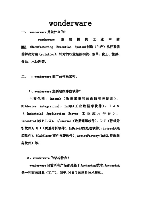
wonderware一、 wonderware是做什么的?wonderware主要提供工业中的MES (Manufacturing Execution System)制造(生产)执行系统的解决方案(solution)。
针对的行业包括钢铁、烟草、化工、能源、食品、水处理等。
二、:wonderware的产品体系架构。
1、wonderware主要包括那些软件?主要包括:intouch(数据采集和画面监视控制用),DI(device integration),InSQL(工业数据库软件),IAS(Industrial Application Server工业应用平台),incontrol(软PLC),I/Oserver(数据通讯软件),DT(停机分析软件),QI(质量分析软件),InBatch(批处理软件),intrack(跟踪软件),SCADAlarm(事件报警软件),ActiveFactoty(InSQL终端服务软件)等。
2、wonderware的架构特点?wonderware目前所有产品都是基于ArchestrA技术。
ArchestrA 是一种面向对象(工厂),基于.NET的软件技术架构。
三、wonderware的产品亮点。
简易的(容易安装和使用),高可靠性(通过冗余和备份确保数据安全),先进性(同microsoft合作的技术领先),高开放性(方便的数据访问,支持众多PLC),高扩展性,有效性,集成性(方便的数据交换和通讯,上千种的I/Oserver,有Tookit供用户开发IOserver,RPM快速协议开发工具)。
wonderware和microsoft是金牌合作伙伴,致力于将微软技术带入工业现场,被成为工业界的微软。
智能工厂,实时决策(powering intelligent plant decisions in real time).协助用户快速集成,掌握和运用实时信息,进行智能决策,提高企业效益。
- 1、下载文档前请自行甄别文档内容的完整性,平台不提供额外的编辑、内容补充、找答案等附加服务。
- 2、"仅部分预览"的文档,不可在线预览部分如存在完整性等问题,可反馈申请退款(可完整预览的文档不适用该条件!)。
- 3、如文档侵犯您的权益,请联系客服反馈,我们会尽快为您处理(人工客服工作时间:9:00-18:30)。
▪ Multi-user development environment ▪ Component-based plant application model ▪ Self documenting
Application Server Galaxy
Galaxy Repository
Single computer and software where the Galaxy database is located.
Wonderware Application Server
+++ Scan-based system. Highlights
Support Section 6: Application Planning
Lab 2 – Identifying the Mixer
Course Description and Objectives
Course Description
The System Platform – Part 1 training course is a 4-day instructor-led course designed to give the knowledge necessary to develop and support applications with Wonderware Application Server.
System Platform
Clients
Microsoft Technologies & Industry Standards
Wonderware System Platform
InTouch
(Visualization)
Wonderware Clients
ActiveFactory
(Analysis Client)
ArchestrA
It provides a unified environment for visualization, plant history, device communications and automation application integration.
Application Server’s application, configuration information and project database.
Software Applications
3rd Party Controllers
Concepts and Terminology
It is an open and extensible system of components based on a distributed, object-oriented design.
System Platform
Module 1: Introduction
Contents
Section 1: Course Introduction Section 2: Wonderware System Platform
Lab 1 – Creating a Galaxy Section 3: The ArchestrA IDE Section 4: Automation Objects Section 5: System Requirements, Licensing and
• Be able to troubleshoot applications in a standalone and networked environment.
Wonderware System Platform
Project Specific Work
Industry Packs Function Specific Modules
System Platform 3.1
Wonderware® System Platform 3.1
System Platform
Agenda
Contents
Module 1: Introduction Module 2: Application Infrastructure Module 3: Application Objects Module 4: Extending the Objects Module 5: Alarms and History Module 6: Security Module 7: Galaxy Maintenance Module 8: Device Integration Products Module 9: Multi-Node Applications
Information Server CAL
(Report Client)
Wonderware System Platform
Application Server
Historian
Information Server
Device Integration Prodቤተ መጻሕፍቲ ባይዱcts
3rd Party Data Sources
Course Objectives
• Understand the ArchestrA® technology and how it is applicable to the plant floor environment.
• Become familiar with developing objects and instances configuring applications using the Integrated Developing Environment.
System Platform
Clients
Microsoft Technologies & Industry Standards
Wonderware System Platform
Project Specific Work
Industry Packs Function Specific Modules
▪ Leverage the .NET Framework for the Automation World
▪ Object-based application
▪ One global networked namespace
▪ Centralized configuration and security