Cherry 系列航空铆钉介绍
cherry航空铆钉的基本资料
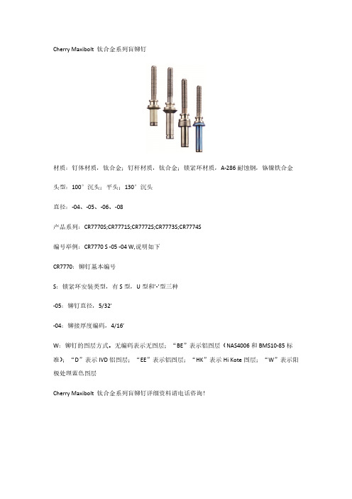
Cherry Maxibolt 钛合金系列盲铆钉材质:钉体材质,钛合金;钉杆材质,钛合金;锁紧环材质,A-286耐蚀钢,铬镍铁合金头型:100°沉头;平头;130°沉头直径:-04、-05、-06、-08产品系列:CR7770S;CR7771S;CR7772S;CR7773S;CR7774S编号举例:CR7770 S -05 -04 W,说明如下CR7770:铆钉基本编号S:锁紧环安装类型,有S型,U型和’-’型三种-05:铆钉直径,5/32’-04:铆接厚度编码,4/16’W:铆钉的图层方式。
无编码表示无图层;“BE”表示铝图层(NAS4006和BMS10-85标准);“D”表示IVD铝图层;“EE”表示铝图层;“HK”表示Hi Kote图层;“W”表示阳极处理蓝色图层Cherry Maxibolt 钛合金系列盲铆钉详细资料请电话咨询!Cherry Maxibolt系列盲铆钉材质:钉体材质,合金钢;钉杆材质,合金钢;锁紧环材质,耐蚀钢头型:100°沉头;平头直径:-04、-05、-06、-08、-10产品系列:CR7310系列;CR7620系列;CR7311系列;CR7621系列;CR7340系列;CR7650系列;CR7341系列;CR7651系列编号举例:CR7770 S -05 -04 W,说明如下CR7310:铆钉基本编号S:锁紧环安装类型,有S型,U型和’-’型三种-05:铆钉直径,5/32’-04:铆接厚度编码,4/16’W:铆钉的图层方式。
无编码表示无图层;“BE”表示铝图层(NAS4006和BMS10-85标准);“D”表示IVD铝图层;“EE”表示铝图层;“HK”表示Hi Kote图层;“W”表示阳极处理蓝色图层Cherry Maxibolt系列盲铆钉详细资料请电话咨询!Cherry Max系列盲铆钉材质:5056铝钉体/铝合金钉杆(50KSI抗剪切力);5056铝钉体/耐蚀钢钉杆(50KSI抗剪切力);monel钉体/耐蚀钢钉杆(75KSI抗剪切力);镍合金600钉体/Inconel X-750钉杆(75KSI 抗剪切力)头型:MS20470标准圆头;MS20426标准100°沉头;NAS1907标准100°沉头;平角沉头;120°沉头直径:-04、-05、-06、-08产品系列:CR3212、CR3213、CR3214、CR3222、CR3222TU、CR3223、CR3223TU、CR4223、CR3242、CR3242A-4-02.5、CR3242BT-4-02、CR3243、CR3245、CR3246、CR3252、CR3252TU、CR3253、CR3253HS、CR3253TU、CR3255、CR3280、CR3281、CR3522、CR3522TU、CR3523、CR3523HC-5、CR3523TU、CR3524、CR3552、CR3552、TUCR3553、CR3553-5-02.5、CR3553-5-03.5、CR3553TU、CR3555、CR3556、CR3822、CR3823、CR3852、CR3853编号举例:CR3 24 2 -6 -04 W,说明如下CR3:铆钉基本编号24:铆钉类型和材质2:头型,偶数表示平头;奇数表示沉头-6:铆钉直径,5/32’-04:铆接厚度编码,4/16’W:铆钉的图层方式。
航空钣金维修-紧固件

3.1盲钉的分类
1.Cherry系列,如cherry lock(cr2)、cherry Max(cr3)、cherry maxibolt(cr7) 2.NAS系列,NAS1921XX(凸头)、NAS1919XX 3.BACR15XX系列 4.MS9035XXX系列 (工作中用的最多的主要是cherry系列以及NAS系列,下面主要讲述一下这两个件
2.Rivet(铆钉)
2.1、Rivet(铆钉)
一般对于铆钉材质,可以根据铆钉头上面的标志来判断区分,可以参照下面图
说明一下,DD钉经过了热处理,使用时在低温状态下取出来,在短时 间内尽早使用完
2.1、Rivet(铆钉)
2.1、Rivet(铆钉)
接下来说一下铆钉的件号规律特点,件号主要是规范不同,后面的几乎大同小异没 啥区别。先举几个列子:
航空紧固件
接下来我将逐步介绍一下本人在航空领域所使用频率高的紧固件,包括紧固件安装拆除 以及相应件号规律等,定义性的东西网上有大把就不说了。(以下均是本人靠经验总结, 仅供参考学习)
董汪同学 2020-05-11
一、紧固件的种类(包括但不局限以下)
1. Screw、Bolt、Nut plate 2. Rivet 3.Blind rivets 4.ASP 5.JO-BOLT 6.HI-LOK和HI-LITE 7、其他
③.NAS10976AD8
这种美国通用标准规范的铆钉不多,会在盲钉中常见到,NAS1097和NAS1200代表小 埋,后面的标码位置跟前面的表示的一样。不过需要注意的是对于小埋,它的特性是 shear 即抗剪力,而对于大埋的特性是tension即抗拉。
2.2、铆钉的安装
①、对于件号的选取主要参照手册,不过如果手册中对于长度的选取说以实际为主的话, 这时候就需要用勾尺勾长度来选择件号长度。
Bobtail航空铆钉专用安装工具(哈克huck)系列资料
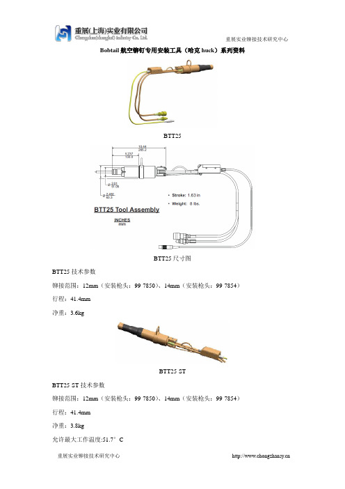
Bobtail航空铆钉专用安装工具(哈克huck)系列资料BTT25BTT25尺寸图BTT25技术参数铆接范围:12mm(安装枪头:99-7850)、14mm(安装枪头:99-7854)行程:41.4mm净重:3.6kgBTT25-STBTT25-ST技术参数铆接范围:12mm(安装枪头:99-7850)、14mm(安装枪头:99-7854)行程:41.4mm净重:3.8kg允许最大工作温度:51.7°C允许最大液压流量:7.6l/mBTT25-DTBTT25-DT技术参数铆接范围:12mm(安装枪头:99-7850)、14mm(安装枪头:99-7854)行程:41.4mm净重:3.8kg允许最大工作温度:51.7°C允许最大液压流量:7.6l/mBTT35LSBTT35SLBTT35LS技术参数铆接范围:12mm(安装枪头:99-7820)、14mm(安装枪头:99-7824)16mm(安装枪头:99-7821、20mm(安装枪头:99-7822)行程:63.5mm净重:4.7kg最大拉力:154kNSFBTT20-ITSFBTT20-IT尺寸图SFBTT20-IT技术参数铆接范围:12mm(安装枪头:99-7880)、14mm(安装枪头:99-7884)、16mm(安装枪头:99-7881)行程:50.8mm净重:4.5kg最大拉力:92kN允许最大工作温度:51.7°CSFBTT20-STSFBTT20-ST尺寸图SFBTT-20ST技术参数铆接范围:12mm(安装枪头:99-7880)、14mm(安装枪头:99-7884)、16mm(安装枪头:99-7881)行程:50.8mm净重:4.08kg最大拉力:92kN允许最大工作温度:51.7°CSFBTT20-DTSFBTT20-DT尺寸图SFBTT20-DT技术参数铆接范围:12mm(安装枪头:99-7880)、14mm(安装枪头:99-7884)、16mm(安装枪头:99-7881)行程:50.8mm净重:3.85kg最大拉力:92kN允许最大工作温度:51.7°CBTT35BTT35尺寸图BTT35SRBTT35SR尺寸图BTT35/BTT35SR技术参数铆接范围:16mm(安装枪头:99-7851)行程:41.3mm净重:5.9kgBTT35-ST BTT35-ST技术参数铆接范围:16mm(安装枪头:99-7851)行程:41.4mm净重:5.0kg允许最大工作温度:51.7°C允许最大液压流量:7.6l/mBTT35-DT BTT35-DT技术参数铆接范围:16mm(安装枪头:99-7851)行程:41.4mm净重:5.0kg允许最大工作温度:51.7°C允许最大液压流量:7.6l/mBTT57BTT57尺寸图BTT57技术参数铆接范围:20mm(安装枪头:99-7852)行程:55.9mm净重:9.3kgBTT57-STBTT57R-STBTT57尺寸图BTT57-ST/BTT57R-ST技术参数铆接范围:16mm(安装枪头:99-7851)行程:55.9mm净重:10.1kg最大拉力:278kN允许最大工作温度:51.7°C允许最大液压流量:7.6l/mBTT57-DTBTT57-DT技术参数铆接范围:16mm(安装枪头:99-7851)行程:55.9mm净重:10.1kg最大拉力:278kN允许最大工作温度:51.7°C允许最大液压流量:7.6l/m。
波音飞机常用紧固件的识别和选用

波音飞机常用紧固件的识别和选用一,实心铆钉1 识别:通常铆钉的直径是以1/32英寸(0.8mm)为单位的,长度是以1/16英寸为单位的。
以下是常用铆钉的标志和件号。
BACR15BA-----波音通用的100℃平头铆钉。
BACR15BB-----波音通用的半圆头铆钉。
BACR15CE-----波音通用的100℃剪切头铆钉。
常用材料代码:代码合金头部标志A 1100 /B 5056 凸起十字AD 2117 凹点D 2017 凸点DD 2024 二条凸起棒KE 7075 凸起环各种材料铆钉的应用:1100-F 纯铝铆钉,不能用于结构修理。
5056-H32 铝镁铆钉。
用于镁结构的修理。
2117-T3 可用于各种结构修理。
常用于蝴蝶螺帽的安装和疲劳关键部位的修理。
可用作液封紧固件。
2017-T3 可用于各种结构修理。
常用于蝴蝶螺帽的安装和疲劳关键部位的修理。
不可用作液封紧固件。
2024-T31 冰箱铆钉。
使用前必须放在冰箱中保存,不能用于蝴蝶螺帽的安装。
主要用于机翼上。
7050-T73 主要用于高强度结构的修理。
举例:BACR15 BA 5 D 7①②③④⑤①②-波音通用的100℃平头铆钉。
③铆钉的直径为5/32英寸(4mm)。
④材料为2017。
⑤铆钉的长度为7/16英寸。
BACR15 BB 5 AD 9①②③④⑤①②-波音通用半圆头铆钉。
③铆钉的直径为5/32英寸(4mm)。
④材料为2117。
⑤铆钉的长度为9/16英寸。
BACR15 CE 5 DD 8①②③④⑤①②-波音通用剪切头铆钉③铆钉的直径为5/32英寸(4mm)。
④材料为2024⑥铆钉的长度为8/16英寸。
2铆钉的选择选用铆钉时应考虑以下因素:①铆钉的头类型应该由安装位置确定。
②只要可能要选择与被铆接件材料相同的铆钉。
③在一般修理件上,通常使用2117-T3铆钉。
该材料铆钉俗称“外场铆钉”但要注意决不能用2117--T3铆钉代替2024-T3铆钉及2017-T3铆钉。
结构修理常用紧固件对照

结构修理常用紧固件对照东航工程技术公司上海定检部结构修理车间概述在飞机结构修理中,由于材料、位置、环境等因素的影响,往往使用各种不同类型的紧固件,以满足其修理要求。
目前,东航有空客、波音等机种,在修理中使用的紧固件因飞机制造厂家的不同而造成牌号不一致,给飞机结构修理带来了许多困难。
为了解决这个困难,我们针对飞机结构修理中所使用的紧固件,结合飞机结构修理手册,飞机修理指南和CHERRY公司提供的资料等,将在飞机结构修理中经常使用的紧固件进行分类,详细介绍了紧固件的材料、外形、特征和强度,对一些紧固件的牌号进行了比较。
这样,方便了修理人员在修理过程中选择合适的等效代用品。
编者2008年9月目录页数常用铆钉和紧固件材料强度表 (4)盲铆钉(垫片)牌号对照表 (5)盲铆钉(锁环)牌号对照表 (6)常用铆钉表 (7)CHERRY MAX有加大(-4~-8) (8)HUCK拉铆钉有加大 (8)常用拉铆钉表 (9)CHERRY LOCK 仅有加大(-4~-6) (9)常用实芯铆钉表 (10)紧固件材料强度表 (10)实芯铆钉、拉铆钉的制孔 (11)紧固件间距 (12)机翼上紧固件边距 (12)紧固件边距2 (12)公制钻头 (13)英制螺纹钻 (14)英制扩孔钻 (14)英制钻头 (15)紧固件拉枪和拉枪头子(HUCK) (16)紧固件拉枪和拉枪头子(CHERRY)…………………第17~18页常用铆钉表紧固件材料强度表CHERRY MAX (垫片)----NAS 盲铆钉牌号对照表注:100度埋头-----MS20426铆钉头型。
100度小埋头-----NAS1097铆钉头型。
凸头-----MS20470铆钉头型。
*凸头与埋头复合型,通常用于复合材料。
CHERRY LOCK(锁环)---NAS 盲铆钉牌号对照表注:100度埋头-----MS20426铆钉头型。
100度小埋头-----NAS1097铆钉头型。
凸头-----MS20470铆钉头型。
铆钉基本知识与用途的介绍

铆钉基本知识与用途的介绍铆钉是在铆接中,利用自身形变或过盈连接被铆接件的零件。
铆钉种类很多,而且不拘形式。
常用的有半圆头、平头、沉头铆钉、抽芯铆钉、空心铆钉,这些通常是利用自身形变连接被铆接件.铆钉的种类很多BS 沉头铆钉、BS管状铆钉、BS平锥头铆钉、BS平头铆钉、BS半圆头铆钉、BS无头铆钉、BS大扁圆头铆钉、BS扁圆头铆钉、BS扁平头铆钉、BS扁、BS圆柱头半空心铆钉、BS黄铆钉、BS扁头铆钉、BS圆头铆钉、BS击芯铆钉、BS锥头铆钉、BS拉铆钉、BS芯铆钉、BS半空心铆钉、BS标牌铆钉、BS半沉头铆钉、BS沉头铆钉、BS管状铆钉、BS平锥头铆钉、BS平头铆钉、BS半圆头铆钉、BS无头铆钉、BS 大扁圆头铆钉、BS扁圆头铆钉、BS扁平头铆钉等,地域上的限制也产生了很多地方的名称,但是在规格上,应该详细的注明:头部形状直径*头部厚度*管径*长度(不包括头部厚度)*孔径*孔深度,通常情况下,孔径和深度已有了标准可以省略,如果您没有图纸或图片,就应该包括这些要素,再告知材料,就基本上能直接生产了。
空心铆钉通常用于服饰,鞋类等行业,实心需要再次铆接,用于重工件联结,常为不可拆结构,半空心铆钉应用最为广泛,束口(线径尾部较小)钉使用硬质线材制造,能不需预孔穿透0.5mm厚度内的钢板,铆钉不能弯曲变形,广泛应用在密码箱,旅行箱和军用箱包上面,中空钉(半空心铆钉)则使用软线制造,一般要求铆开后不能开裂,有很多种类型,目前对一些玩具上面的轴已经开始大面积使用半空心钉或子母钉替代,能大幅降低生产成本。
抽芯和击芯铆钉则多用于较为薄软材料的铆接,一般要求不严格,制造用材通常用塑性较好的材料生产。
半圆头铆钉主要用于随较大横向载荷的铆接场合,应用最广。
平锥头铆钉由于钉头肥大,能耐腐蚀,常用于船壳、锅炉水箱等腐蚀强烈的铆接场合。
沉头、1200沉头铆钉主要用于表面须平滑,随载荷不大的铆接场合。
半沉头、1200半沉头铆钉主要用于表面须平滑,随载荷不大的铆接场合。
铆钉的作用及使用方法【详细】
内容来源网络,由深圳机械展收集整理!更多紧固件展示,就在深圳机械展。
铆钉的作用:就是取代螺丝连接的一种方法,使多个零件连接在一起,既可紧固,又可使零件能转动(使用台阶铆钉)使用方法:1、可人工铆接,效率不高,适合小批量生产;2、可机器铆接,人与机器配合;生产效率高,适合大批量生产,实现半自动化作业,是人工铆接效率的5-10倍。
可大大降低生产成本,缩短生产周期。
性价比是使用螺丝成本1/4,比螺丝连接速度快3倍。
(买螺丝你必须买螺帽)其中就增加了成本;就算你用电批或是风批上螺丝,也快不过铆钉机铆接。
有用过铆钉的人都知道,能用铆钉的结构都会用因为你可以节省不必要的开支。
提高你产品的竟争力!在我们平时使用钣金机箱机柜的过程中,我们可以发现钣金机箱机柜中有很多的铆钉,那么这些铆钉又有着怎样的作用呢?其实这些铆钉是保证钣金机箱机柜连接牢固性的。
那么,在如此情境之下,我们对于其就有了一定的要求:1.可应用于高端的技术场合工业铝型材结构框架;2.可应用于震动环境的方钢框架系统;3.可应用于强大理线及设备安装的铝型材与板金结构框架系统。
铆钉性能抗剪性能铆钉在航空航天产品的结构连接中主要承受剪力,所以,在一般的铆钉标准中,都规定了铆钉的最小破坏剪力指标。
随着试验方法的改进和规范,越来越多的标准规定双剪指标。
与单剪相比,双剪试验的结果更加准确、可靠。
铆接性能铆接性是指铆接完成后铆成头的成型要求。
铆成头成型的好坏,直接影响铆接质量。
因此,在国内航空航天的铆接标准中对铆钉的铆接性都有严格要求,而一般用途的普通铆钉尚没有规定铆接性要求。
铆接性和强度是两项互相矛盾的指标,强度越高,铆接性越差。
一般情况下,铆接后铆成头的高度为0.35d-0.4d,铆成头直径在1.4d以上。
同时,对铆成头上出现的裂纹有严格要求,裂纹只允许在铆城投柱面上出现,不能贯穿至顶面,总数不超过3条,宽度与深度不超过0.07mm。
铆钉的用途和品种简介半圆头铆钉主要用于随较大横向载荷的铆接场合,应用最广。
飞机铆接知识点总结
飞机铆接知识点总结一、铆接的原理1.1 铆接的定义铆接是利用机械设备将铆钉或铆钉组合件与被连接零件固定在一起的机械连接方法。
铆钉主要有实心铆钉、空心铆钉、扁平面铆钉等,其材料通常选用铝合金、钛合金、高强度钢等。
1.2 铆接的原理铆接的原理是通过铆接机器对金属件进行挤压,使铆钉与连接零件之间产生永久性的连接。
在挤压的过程中,铆钉的头部会被挤压成为圆形或者扁平形,从而将连接零件牢固地固定在一起。
1.3 铆接的优点铆接的优点主要有连接牢固、不易腐蚀、结构简单、可逆装拆、机械性能好等。
1.4 铆接的缺点铆接的缺点主要是铆接过程需要专用设备,且安装过程较为复杂,对操作人员的技术要求较高。
二、铆接材料2.1 铆接材料的选择原则在飞机铆接中,通常选择的铆接材料主要包括铝合金、钛合金、不锈钢等。
选择铆接材料的原则如下:(1)与连接材料相似的材料(2)强度高、硬度适中的材料(3)抗腐蚀性好的材料(4)易加工、易焊接、易切削的材料2.2 铆接材料的特点不同的铆接材料具有不同的特点,如铝合金具有轻质、耐热、易加工等特点;钛合金具有高强度、耐腐蚀等特点;不锈钢具有抗腐蚀性强、强度高等特点。
2.3 铆接材料的选择在飞机铆接过程中,必须根据飞机零部件的材料特性和工作环境的要求,选择合适的铆接材料。
同时,还要根据铆接材料之间的相容性和连接强度进行综合考虑,以保证整个飞机结构的可靠性和安全性。
三、铆接工艺3.1 铆接工艺流程飞机铆接的工艺流程主要包括以下几个步骤:零件准备、钻孔、铆钉安装、铆接和质量检验。
(1)零件准备:包括对零件进行清洁、涂漆、喷砂等处理,以保证材料表面的质量和干净度。
(2)钻孔:根据设计要求,在零件上钻出相应直径和深度的孔,以便进行铆接。
(3)铆钉安装:将铆钉插入预先钻好的孔中,使其头部稍微凸出零件表面。
(4)铆接:使用铆接机器对铆钉头部进行挤压,使其与连接零件之间产生永久性的连接。
(5)质量检验:对铆接后的零部件进行外观和尺寸检查,以保证其质量和精度达标。
cherry铆钉枪系列参数
cherry G800手动液压铆接工具铆接范围:3.2-4.8mm cherryMAX、SST铆钉、maxibolt铆钉重量:0.86kg拉力:14000N/@5bar行程:19mm全长:197mm全高:163mmcherry G702A气动液压铆接工具铆接范围:-3、-4;2.5mm,3.0mmnut-plate铆钉重量:1.59kg拉力:4900N@6.2bar行程:19mm安装速度:1.0sec工作气压:6.2-7.6barcherry G902/902-15轻型气动铆接工具铆接范围:3/32、1/8nut-plate铆钉;3/32'CherryLOCK A 铆钉拉力:2450N@6.2bar、3266N@8.2bar行程:19mm安装速度:1.0sec工作气压:6.2-8.2barcherry G704B CherryMAX铆钉安装工具铆接范围:1/8、5/32、3/16 CherryMAX铆钉重量:1.93kg拉力:13790N@6.2bar行程:13mm安装速度:1.0sec工作气压:6.2-7.6barG704B-SR/G704B-40SH CherryMAX铆钉安装工具铆接范围:1/8、5/32、3/16 CherryMAX铆钉3/32'CherryLOCK A 铆钉重量:2.04kg(动力单元)拉力:14029N@6.2bar行程:13.2mm安装速度:1.0sec工作气压:6.2-8.2bar软管长度:3ft/8ftcherry G746A CherryMAX铆钉安装工具铆接范围:1/8、5/32、3/16 CherryMAX铆钉;1/8、5/32、3/16CherryMAX ‘AB’铆钉;3/32、1/8、5/32、3/16CherryLOCK‘A'铆钉重量:1.93kg拉力:8230N@6.2bar行程:22.2mm安装速度:1.0sec工作气压:6.2-7.6barcherry G747 CherryMAX铆钉安装工具铆接范围:1/8、5/32、3/16 CherryMAX铆钉重量:1.59kg拉力:9340N@6.2bar行程:11.1mm安装速度:1.0sec工作气压:6.2-7.6barcherry G689 CherryLOCK铆钉安装工具铆接范围:至1/4 CherryLOCK铆钉重量:5.9kg拉力:16900N@6.2bar行程:11.1mm安装速度:1.0sec工作气压:6.2-7.6barcherry G695B CherryLOCK铆钉安装工具铆接范围:至1/4 CherryLOCK铆钉重量:7.7kg(动力单元)拉力:8947N@6.2bar行程:15.88mm安装速度:1.0sec工作气压:6.2-7.6bar软管长度:8ftcherry G700 CherryLOCK铆钉安装工具铆接范围:至1/8 CherryLOCK铆钉重量:2.6kg拉力:5458N@6.2bar行程:23mm安装速度:1.0sec工作气压:6.2-7.6barcherry G784 CherryLOCK铆钉安装工具铆接范围:至1/4 CherryLOCK铆钉重量:3.63kg拉力:11570N@6.2bar行程:22.2mm安装速度:1.0sec工作气压:6.2-7.6barcherry G686B-S CherryLOCK铆钉安装工具铆接范围:至1/4 CherryLOCK铆钉重量:总重7.71kg;枪体重2.27kg拉力:11570N@6.2bar行程:36.5mm安装速度:1.0sec工作气压:6.2-7.6bar软管长度:8ftcherry G83 Lockbolt铆钉安装工具铆接范围:至3/16 Lockbolt铆钉;至1/4CherryMAX铆钉重量:2.25kg拉力:11570N@6.2bar;行程:11.1mm安装速度:1.0sec工作气压:6.2-7.6barcherry G84 Lockbolt铆钉安装工具cherr铆接范围:至1/4 Lockbolt铆钉;Maxibolt铆钉;Maxibolt plus铆钉;CherryMAX铆钉;CherryMAX’A'铆钉;CherryMAX“AB”铆钉;重量:3.5kg拉力:25600N@6.2bar;行程:14.3mm安装速度:1.0sec工作气压:6.2-7.6bary G84-LS Lockbolt铆钉安装工具铆接范围:至1/4 Lockbolt铆钉;Maxibolt铆钉;Maxibolt plus铆钉;CherryMAX铆钉;CherryMAX’A'铆钉;CherryMAX“AB”铆钉;重量:总重5.35kg;枪体重0.91kg拉力:25320N@6.2bar;行程:13.5mm安装速度:1.0sec工作气压:6.2-7.6bar软管长度:10ftcherry G85D-S Lockbolt铆钉安装工具铆接范围:至3/8 Lockbolt铆钉重量:总重8.75kg;枪体重1.95kg拉力:31000N@6.2bar;行程:18.3mm安装速度:1.0sec工作气压:6.2-7.6bar软管长度:8ftcherry G87D Lockbolt铆钉安装工具铆接范围:至3/8 Lockbolt铆钉;CherryMAX铆钉;CherryMAX‘AB'铆钉;Maxibolt铆钉重量:4.875kg拉力:42300N@6.2bar;行程:14.3mm安装速度:1.0sec工作气压:6.2-7.6barcherry直型拉枪头H702-3NPR、H702-4NPR、H701B-456、H746(A)-4MBC/-5MBC/-6MBC、H955-3/-4/-5/-6、H9015-3C/-4C/-5C/-6C、H747-3NPR、H9040-4C/-5C/-6C/-8C、H9055-3/-4/-5/-6、H680B200A、H680B208、H681-3C/-4C/-5C/-6C/-8C、H83B-5MB/-6MB、H513-04-20/-35/-60、H513-05-20/-35/-60、H84C-8MB、H84A-8、H84-8CLA、H513S-05/-06/-08/-10/-12、H744-5MB/-6MBcherry偏移型拉枪头H782系列:782-456、-6AL、-5BB、-4MBC、-5MBC、-6MBC、-3,886-003、-004、-005、-006;H781-456、H872-8、H563-5B、H563-6B、H562-5B、H562-6B、H562-8B、H563SP-4B、H563SP-5B、H563SP-6B、H827-8、H856-6MBcherry 90°直角拉枪头H753A-456、H828-8/-5MB/-6MB、H690-4C/U、-5C/U、-6C/U、-8C/U。
Cherry 系列航空铆钉介绍
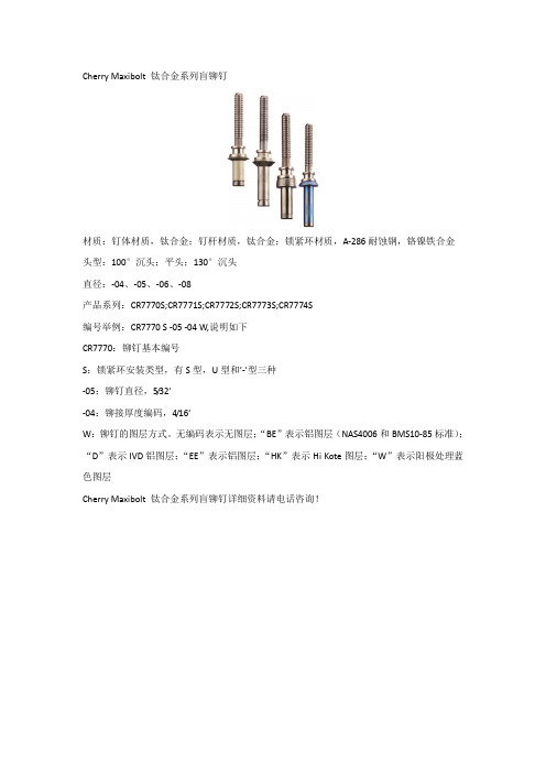
Cherry 系列航空铆钉介绍Cherry Maxibolt 钛合金系列盲铆钉材质:钉体材质,钛合金;钉杆材质,钛合金;锁紧环材质,A-286耐蚀钢,铬镍铁合金头型:100°沉头;平头;130°沉头直径:-04、-05、-06、-08产品系列:CR7770S;CR7771S;CR7772S;CR7773S;CR7774S编号举例:CR7770 S -05 -04 W,说明如下CR7770:铆钉基本编号S:锁紧环安装类型,有S型,U型和’-’型三种-05:铆钉直径,5/32’-04:铆接厚度编码,4/16’W:铆钉的图层方式。
无编码表示无图层;“BE”表示铝图层(NAS4006和BMS10-85标准);“D”表示IVD铝图层;“EE”表示铝图层;“HK”表示Hi Kote图层;“W”表示阳极处理蓝色图层Cherry Maxibolt 钛合金系列盲铆钉详细资料请电话咨询!Cherry Maxibolt系列盲铆钉材质:钉体材质,合金钢;钉杆材质,合金钢;锁紧环材质,耐蚀钢头型:100°沉头;平头直径:-04、-05、-06、-08、-10产品系列:CR7310系列;CR7620系列;CR7311系列;CR7621系列;CR7340系列;CR7650系列;CR7341系列;CR7651系列编号举例:CR7770 S -05 -04 W,说明如下CR7310:铆钉基本编号S:锁紧环安装类型,有S型,U型和’-’型三种-05:铆钉直径,5/32’-04:铆接厚度编码,4/16’W:铆钉的图层方式。
无编码表示无图层;“BE”表示铝图层(NAS4006和BMS10-85标准);“D”表示IVD铝图层;“EE”表示铝图层;“HK”表示Hi Kote图层;“W”表示阳极处理蓝色图层Cherry Maxibolt系列盲铆钉详细资料请电话咨询!Cherry Max系列盲铆钉材质:5056铝钉体/铝合金钉杆(50KSI抗剪切力);5056铝钉体/耐蚀钢钉杆(50KSI抗剪切力);monel 钉体/耐蚀钢钉杆(75KSI抗剪切力);镍合金600钉体/Inconel X-750钉杆(75KSI抗剪切力)头型:MS20470标准圆头;MS20426标准100°沉头;NAS1907标准100°沉头;平角沉头;120°沉头直径:-04、-05、-06、-08产品系列:CR3212、CR3213、CR3214、CR3222、CR3222TU、CR3223、CR3223TU、CR4223、CR3242、CR3242A-4-02.5、CR3242BT-4-02、CR3243、CR3245、CR3246、CR3252、CR3252TU、CR3253、CR3253HS、CR3253TU、CR3255、CR3280、CR3281、CR3522、CR3522TU、CR3523、CR3523HC-5、CR3523TU、CR3524、CR3552、CR3552、TUCR3553、CR3553-5-02.5、CR3553-5-03.5、CR3553TU、CR3555、CR3556、CR3822、CR3823、CR3852、CR3853编号举例:CR3 24 2 -6 -04 W,说明如下CR3:铆钉基本编号24:铆钉类型和材质2:头型,偶数表示平头;奇数表示沉头-6:铆钉直径,5/32’-04:铆接厚度编码,4/16’W:铆钉的图层方式。
Cherry G800 手力瞬间紧固器说明书

STROKE PULLING FORCE (adjustable)POWER SOURCEWEIGHT (WITHOUT)PULLING HEAD) 3/4" min.Up to 6000 lbs. Hand Pump1.7 lbs.The Cherry ® G800 is an ergonomic, lightweight hand powered riveter capable of installing a wide variety of blind type fasteners.The all metal design makes this compact and robust tool ideal for use in rugged repair facilities and field repair. The exceptional power multiplication provides up to 6000 Lbs.FEATURES & BENEFITSergonomic designLightweight with cushioned handle and adjustable lever span An internal shock absorber reduces operating shocksSmart power optimization system provides extremely high loads at low hand effort and increased productivityversatileCherryMax® mounting system (same as G704B) compatiblewith our most popular pulling heads like H782, H781-456, H753A-456A full line of slim pulling heads available for a wide variety of blind fastenersreliableThis product was subjected to extensive testing; its quality is backed by the Cherry® reputation for high quality tools.Your Cherry® tools remain the industry leader in after sales support.economicalIt is built to last and to require minimum service. It features: High strength steel and aluminum constructionLeak proof design with advanced seals and built-in redundanciesDurable coatings for use in harsh environmentssimple, cost-effective maintenanceSafe & quick access to wear items (jaws, jaw follower)Visual fluid level indicator and easy to follow troubleshooting guideService, repair, refill in just minutes; no special tools neededTECHNICAL SPECIFICATIONSKIT OPTIONS•G800CMR – This battle damage repair kit includes the G800 riveter equipped with H800, acompact offset (H782), a right angle (H753A-456) pulling heads as well as 886-003 and 782-5BB nose pieces. Additionally, this kit includes a fastener reference guide, grip gauge, andtool documentation (tool manual, tool sheets)•ON-DEMAND KITS- Other kits may be made available at request; please call CHERRY® to discuss your needs.G800KS – service kit: it includes all seals, screws, foam handle, ball bearings and springs.PULLING HEAD SELECTIONYour hand riveter comes with H800 & 782-456; additional nose pieces and pulling heads may be purchased as needed.For Rivetless Nut Plate (RNP) installation, H704-()NP (metallic structure) or H704-()NPC (composite structure); see our tool sheets for more information. For installing other fasteners or RNP removal, call Cherry®; we will be happy to recommend the right configuration. Notes: Items in red, marked with an asterisk (*) are standard components provided with the pulling heads.MODEL NUMBERJAW P/NJAW FOLLOWERNOSE PIECE INSTALLS THE FOLLOWING PRODUCTSCherryMAX, CherryMAX AB: -4, -5, -6 (except 6 Alum)Blindbolt “S” type: -04 & -05MBC Lock Creator: -4, -5, -6NAS1900 "U" type: -4 & -5886-003CherryLOCK “A” Code: -3886-004CherryLOCK “A” Code: -4H800886-005CherryLOCK “A” Code: -5782-010886-002886-006CherryLOCK "A" Code: -6782-5BBBlindbolt “U” Type: -05 782-4MBC Standard MBC: -4782-5MBCStandard MBC: -5782-6MBC Standard MBC: -6782 -6AL CherryMAX "AB" -6 Alum, NAS1900 -4, -5, -6782-33/32” SPR & -3 pull thru NP Rivets RIGHT ANGLE: H753A-456782-4NAS NAS1900, -4 (no shift washer)INSTALLS NAS1400 & 1722 RIVETS782-5NAS NAS1900, -5 (no shift washer)UP TO -04 GRIP782-010886-002782-6NASNAS1900, -6 (no shift washer)*701B18*753A14A*782-456*701B18*753A14A *701B18*753A14A782-010886-002MODEL NUMBER JAW P/N NOSE PIECE INSTALLS THE FOLLOWING PRODUCTSCherryMAX & CherryMAX AB: -4, -5 & -6 (except -6 Alum)Blindbolt “S” type: -04 & -05MBC Lock Creator: -4, -5, -6 NAS1900 "U" type: -4 & -5886-003CherryLOCK “A” Code: -3886-004CherryLOCK “A” Code: -4886-005CherryLOCK “A” Code: -5782-010886-006CherryLOCK "A" Code: -6782-5BB Blindbolt “U” Type: -05 782-4MBC Standard MBC: -4782-5MBC Standard MBC: -5Offset: H782782-6MBC Standard MBC: -6782 -6AL CherryMAX "AB" -6 Al; NAS1900 -4, -5 & -6782-33/32” SPR & -3 pull thru NP Rivets 782-4NAS NAS1900, -4 (no shift washer)782-5NAS NAS1900, -5 (no shift washer)782-010782-6NASNAS1900, -6 (no shift washer)*782-456*701B18*701B18*701B18782-010MODEL NUMBERJAW P/N NOSE PIECE P/NINSTALLS THE FOLLOWING PRODUCTS *652-024CherryMax, "A" Code, "AB" -8 (all materials)652-065Maxibolt Plus -5, 6, 8652-035Maxibolt -8 "S" type 652-065Maxibolt -8 "U" type 652-038Maxibolt -6 "S" type 652-067Maxibolt -6 "U" type744C76865C25*652-043HEAVY DUTY: HD800-8。
cherry航空铆钉的基本资料
Cherry Maxibolt 钛合金系列盲铆钉材质:钉体材质,钛合金;钉杆材质,钛合金;锁紧环材质,A-286耐蚀钢,铬镍铁合金头型:100°沉头;平头;130°沉头直径:-04、-05、-06、-08产品系列:CR7770S;CR7771S;CR7772S;CR7773S;CR7774S编号举例:CR7770 S -05 -04 W,说明如下CR7770:铆钉基本编号S:锁紧环安装类型,有S型,U型和’-’型三种-05:铆钉直径,5/32’-04:铆接厚度编码,4/16’W:铆钉的图层方式。
无编码表示无图层;“BE”表示铝图层(NAS4006和BMS10-85标准);“D”表示IVD铝图层;“EE”表示铝图层;“HK”表示Hi Kote图层;“W”表示阳极处理蓝色图层Cherry Maxibolt 钛合金系列盲铆钉详细资料请电话咨询!Cherry Maxibolt系列盲铆钉材质:钉体材质,合金钢;钉杆材质,合金钢;锁紧环材质,耐蚀钢头型:100°沉头;平头直径:-04、-05、-06、-08、-10产品系列:CR7310系列;CR7620系列;CR7311系列;CR7621系列;CR7340系列;CR7650系列;CR7341系列;CR7651系列编号举例:CR7770 S -05 -04 W,说明如下CR7310:铆钉基本编号S:锁紧环安装类型,有S型,U型和’-’型三种-05:铆钉直径,5/32’-04:铆接厚度编码,4/16’W:铆钉的图层方式。
无编码表示无图层;“BE”表示铝图层(NAS4006和BMS10-85标准);“D”表示IVD铝图层;“EE”表示铝图层;“HK”表示Hi Kote图层;“W”表示阳极处理蓝色图层Cherry Maxibolt系列盲铆钉详细资料请电话咨询!Cherry Max系列盲铆钉材质:5056铝钉体/铝合金钉杆(50KSI抗剪切力);5056铝钉体/耐蚀钢钉杆(50KSI抗剪切力);monel钉体/耐蚀钢钉杆(75KSI抗剪切力);镍合金600钉体/Inconel X-750钉杆(75KSI抗剪切力)头型:MS20470标准圆头;MS20426标准100°沉头;NAS1907标准100°沉头;平角沉头;120°沉头直径:-04、-05、-06、-08产品系列:CR3212、CR3213、CR3214、CR3222、CR3222TU、CR3223、CR3223TU、CR4223、CR3242、CR3242A-4-02.5、CR3242BT-4-02、CR3243、CR3245、CR3246、CR3252、CR3252TU、CR3253、CR3253HS、CR3253TU、CR 3255、CR3280、CR3281、CR3522、CR3522TU、CR3523、CR3523HC-5、CR3523TU、CR3524、CR3552、CR3552、TUCR3553、CR3553-5-02.5、CR3553-5-03.5、CR3553TU、CR3555、CR3556、CR3822、CR3823、CR3852、CR3853编号举例:CR3 24 2 -6 -04 W,说明如下CR3:铆钉基本编号24:铆钉类型和材质2:头型,偶数表示平头;奇数表示沉头-6:铆钉直径,5/32’-04:铆接厚度编码,4/16’W:铆钉的图层方式。
Cherry Aerospace TS-H828-6MB 杠叶拉头工具说明书
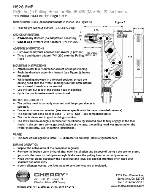
DIMENSIONAL DATA (all measurements in Inches, see Figure 1)Figure 1•Tool Weight (without riveter): 2.1 Lbs (0.9 Kg)CHOICE OF RIVETERS•G744 Cherry Riveters (no adaptation necessary)•G83 or G84 Riveters with Adapters P/N 744-200ADAPTOR INSTRUCTIONS•Remove the bayonet adapter from riveter (if present)•Thread and tighten adapter 744-200 onto the PullingHeadMOUNTING INSTRUCTIONS•Attach riveter to air source for correct piston positioning.•Push the drawbolt assembly forward (see Figure 1), beforemounting•While holding drawbolt in a forward position, thread thepulling head onto the riveter, making sure that both internaland external threads are connected.•Use the jam-nut to lock the pulling head in position.•Cycle the tool to make sure it is functional.BEFORE USE, CHECK IF:•The pulling head is correctly mounted and the proper riveter isselected.•Proper air source is connected (see riveter specification for recommended pressure).•The appropriate nose piece is used (“U” or “S” type – see component table).•The tool is clean and in good working condition.•The Jaws provide enough clearance for the Blindbolt® serrated area to fully engage in the tool freely; if the serrated stems get stuck inside of the jaws, the pulling head was mounted on the riveter incorrectly. See “Mounting Instructions”.USAGE•This tool was designed to install “-6” diameter BlindBolt® (MaxiBolt®) fasteners.DURING OPERATION•Inspect the active area of the nosepiece regularly.•Remove the broken stem by hand after each installation and dispose of them; if the broken stems get stuck, the Jaws do not open enough. Make sure the pulling head is correctly mounted. •Keep the tool clean, especially the nosepiece and jaws; pay special attention when used with sealants and adhesives.•If stem slippage occurs, the Jaws need to be either cleaned or replaced.LOCTITE® is a registered trademark of Henkel Corporation.LUBRIPLATE® is a registered trademark of Fiske Brothers Refining Co. COLLET BOLT 1 1 SCREW 2 CRANK 1 LINK PLATES (SET OF 4) 3 PIN 6DRAWBOLT 1 PIVOT PIN ASSEMBLY 2 NUT 1 ADAPTER FITTING 1FRAME 1 BUTTON 1 COMPRESSION SPRING 1 FOLLOWER 1 JAWS (SET OF 3) 1COLLET 1SLEEVE 1 -6 NOSEPIECE “U” TYPE 1 -6 NOSEPIECE “S” TYPE 1 QTY. PER ASSY.WARRANTYSeller warrants the goods conform to applicable specifications and drawings and will be manufactured andinspected according to generally accepted practices of companies manufacturing industrial or aerospacefasteners. In the event of any breach of the foregoing warranty, Buyer’s sole remedy shall be to returndefective goods (after receiving authorization from Seller) for replacement or refund of the purchase price, at the Seller’s option. Seller agrees to any freight costs in connection with the return of any defective goods, but any costs relating to removal of the defective or nonconforming goods or installation of replacement goods shall be Buyer’s responsibility. SELLER’S WARRANTY DOES NOT APPLY WHEN ANY PHYSICAL OR CHEMICAL CHANGE IN THE FORM OF THE PRODUCT IS MADE BY BUYER. THE FOREGOING EXPRESS WARRANTY AND REMEDY ARE EXCLUSIVE AND ARE IN LIEU OF ALL OTHER WARRANTIES AND REMEDIES; ANY IMPLIED WARRANTY AS TO QUALITY, FITNESS FOR PURPOSE, OR MERCHANTABILITY IS HEREBY SPECIFICALLY DISCLAIMED AND EXCLUDED BY SELLER. This warranty is void if seller is not notified in writing of any rejection of the goods within ninety (90) days after receipt of the goods by buyer.Seller shall not be liable under any circumstances for incidental, special or consequential damages arising in whole or in part from any breach by Seller, AND SUCH INCIDENTAL, SPECIAL, OR CONSEQUENTIAL DAMAGES ARE HEREBY EXPRESSLY EXCLUDED.Our policy is one of continuous development. Specifications shown in this document may be subject to changes introduced after publication.NOTE: The properties, strength, dimensions, installed characteristics and all other information in these materials are for guidance only to aid in the correct selectionof the products described herein and is not intended or implied as part of the above warranty. All applications should be evaluated for functional stability and availablesamples of the described parts can be requested for installed tests, suitability and evaluations.。
飞机铆钉拆除维修方案
飞机铆钉拆除维修方案1. 概述飞机铆钉是飞机结构中常用的连接元件,它们连接起飞机的各个部件。
在飞机维修过程中,有时需要拆除或更换铆钉。
本文档将介绍飞机铆钉拆除维修的相关方案和步骤。
2. 材料和工具在进行飞机铆钉拆除维修之前,需要准备以下材料和工具:•铆钉拆钻•拆锤•铆钉拆钳•清洁剂•润滑剂•手套和护目镜3. 飞机铆钉拆除步骤3.1 准备工作在进行飞机铆钉拆除之前,需进行以下准备工作:1.确定拆除的铆钉数量和位置。
2.工作区域应保持清洁,以免铆钉或其他杂物掉落到敏感部位或引起其它损害。
3.空气压力设定在适当的水平,以便使用铆钉拆钻工具。
4.空气和电力工具的压力供应应该是稳定的。
3.2 铆钉拆除按照以下步骤进行飞机铆钉的拆除:1.使用铆钉拆钳将铆钉头部挤压变形。
2.使用铆钉拆钳或拆锤敲打铆钉头部,使其脱离结构。
3.使用铆钉拆钻,将铆钉的中心孔打通,然后逐渐扩大直到铆钉头部完全从结构中分离。
4.持续观察铆钉拆除过程中结构的变形情况,以防止结构的损坏。
5.清理拆除完的铆钉残片并对结构进行清洁。
3.3 铆钉更换在拆除旧的铆钉后,有时需要更换新的铆钉。
以下是一般的铆钉更换步骤:1.选择正确类型和规格的新铆钉。
2.将新铆钉插入结构中的孔中。
3.使用铆钉枪或手动松紧器将铆钉固定在结构上。
4.确保新铆钉与结构紧密连接,没有松动。
4. 安全注意事项在进行飞机铆钉拆除维修时,应注意以下安全事项:•确保佩戴手套和护目镜,以保护手部和眼睛免受伤害。
•使用铆钉拆钳和拆锤时要小心操作,避免伤到手指。
•确保工作区域的安全,避免铆钉或其他零部件滑落造成伤害。
•在使用铆钉拆钻时,避免太大的力量,以免损坏结构。
5. 维护和清洁使用后的工具和材料需要进行维护和清洁,以确保其性能和寿命。
•铆钉拆钳和拆锤需要定期清洁和润滑,以免生锈。
•铆钉拆钻需要保持锋利,可以使用砂纸进行打磨。
6. 结论飞机铆钉拆除维修是飞机维护过程中的常见操作,我们按照上述步骤和注意事项进行操作,可以保证操作安全并保持飞机结构的完好性。
第七章 飞机特种铆接

(b)窝(b与)窝孔锥柱相交线倒圆
7.1 环槽铆钉的铆接
7.1.2 铆钉长度的选择
环槽铆钉的长度(按公式5-1计算),如图5-3所示 环槽铆钉的光杆只允许凸出夹层的长度为≤1.0mm,不允许凹入。 拉铆型环槽铆钉的长度按公式(5-2)选取。 镦铆型环槽铆钉的长度按公式(5-3)选取。
图5-3 环槽铆钉光杆部分的长度
7.3 螺纹空心铆钉的铆接
7.3.1 技术要求
螺纹空心铆钉孔的直径及其极限偏差见表5-10 制出深为0.2mm的45°倒角 镦头直径见表5-11
7.3.2 铆钉长度的选择 7.3.3 铆接工艺过程
(a)
(b)
(c)
(d)
图5-22 螺纹空心铆钉的施铆过程
7.3 螺纹空心铆钉的铆接
7.3.3 铆接工艺过程
第七章 特种铆接
7.1 环槽铆钉的铆接 7.2 抽芯铆钉的铆接 7.3 螺纹空心铆钉的铆接 7.4 高抗剪铆钉的铆接
7.5 钛合金铆钉的铆接 7.6 工具设备的使用和维护
7.1 环槽铆钉的铆接
铆钉的分类
抗拉型环槽钉
带
按受力形式
环 槽
抗剪型环槽钉
钉套
的 铆
钉
拉铆型环槽钉
按铆接方法
镦铆型环槽钉
7.1 环槽铆钉的铆接
7.2 抽芯铆钉的铆接
抽芯铆钉的铆接属单面铆接。铆钉的种类较多,目前常用的主要有国产的拉丝型 HB5844~HB5893抽芯铆钉和国外的鼓包型,如美国CHERRYMAX公司的CR3000系 列抽芯铆钉。
抽芯铆钉
抽芯铆钉电动枪
7.2 抽芯铆钉的铆接
7.2.1 拉丝型抽芯铆钉的铆接
技术要求 铆钉孔的直径、极限偏差、圆度及表面粗糙度见表5-3 孔的间距和边距极限偏差 芯杆和锁环应平整(见图5-12) 铆接后锁环的位置(见图5-13) 位于气动外缘表面的芯杆 镦头的最小直径(见表5-5) 钉套不允许有开裂和裂纹,锁环不允许有松动现象
Cherry G744 力秤式固定钉合金工具说明书

Original InstructionsG744CherryMAX®Power RiveterNSN5130-01-151-18561224East Warner Ave,Santa Ana,CA92705Tel:1-714-545-5511Fax:1-714-850-6093THE G744TOOLTABLE OF CONTENTS Description (1)Specifications for G744 (1)Safety Warnings (2)How to Use the G744 (3)Maintenance and Repair (3)Fill and Bleed Instructions (4)Trouble Shooting (4)Overhaul (5)Air Valve (5)Head Sub-Assembly (5)Handle Sub-Assembly (6)G744Pulling Heads (6)Installing Pulling Heads (7)Cross Section Drawing of G744 (8)Parts List for G744Riveter (9)Exploded View of G744 (10)Declaration of Conformity.......................................................................................................................................Back Cover DESCRIPTIONThe Cherry G744is a pneumatic-hydraulic tool designed specifically forthe most efficient installation of1/4”CherryMAX®rivets.However,with the proper pulling heads and adapter,this tool can install other sizesand types of rivets.This tool utilizes straight,offset and right-anglepulling heads.Extensions are available for extending the pullingheads to reach limited access areas.Refer to the pulling head sectionfor the correct pulling head part number for the rivet to be installed.Its all metal housing makes this tool extremely durable for use in a shopenvironment.It can be operated in any position with one hand.A stemcatcher bag may be ordered separately and attached to eliminate costlyclean-up.SPECIFICATIONS FOR G744Cherry Aerospace’(CHERRY)policy is one of continuous development.Specifications shown in this document may be subject to change whichmay be introduced after publication.For the latest information alwaysconsult CHERRY.AIR PRESSURE90to110PSI(6.2to7.6bar)STROKE0.625inch(15.88mm)PULLING FORCE3800Pounds(16.90kN)@90PSI(6.2bar)CYCLE TIME Approximately one secondWEIGHT7Pounds(3.18kg)NOISE LEVEL72dB(A)VIBRATION Less than2.5m/s2AIR CONSUMPTION0.31SCF/cycle(8.78L/cycle)S AF E TY W AR NI NG S∙Operating this tool with a damaged or missing stem deflector,or using the deflector as a handle, may result in severe personal injury.The pin deflector should be rotated until the aperture is facing away from the operator and other persons working in the vicinity.∙Approved eye protection should be worn when operating,repairing,or overhauling this tool.∙Do not use beyond the design intent.∙Do not use substitute components for repair.∙Any modification to the tool,pulling heads,accessories or any component supplied by CHERRY®, or their representatives,shall be the customer’s entire responsibility.CHERRY®will be pleased to advise on any proposed modification.∙The tool must be maintained in a safe working condition at all times and examined at regular intervals for damage.∙Before disassembling the tool for repair,refer to the maintenance instructions.All repairs shall be undertaken only by personnel trained in CHERRY®installation tools.Contact CHERRY®with your training requirement.∙Always disconnect the air line from the tool inlet before attempting to service,adjust,fit or remove any accessory.∙Do not operate the tool when it is directed at any person.∙Ensure that the vent holes do not become blocked or covered and that air line hoses are always in good condition.∙Avoid excessive contact with the hydraulic fluid to minimize the possibility of skin rashes.Care should be taken to wash thoroughly.∙Operating air pressure should not exceed110psi(7.6bar).∙Do not operate the tool without the pulling head in place.∙Do not operate the tool unless the handle base(25)is fully secured by the retaining ring(26).∙All retaining rings,screwed end caps,air fittings,trigger valves and pulling heads should be attached securely and examined at the end of each working shift.∙Do not pull rivet in the air.∙The precautions to be used when using this tool must be explained by the customer to all operators.Any questions regarding the correct operation of the tool and operator safety should be directed to CHERRY®.∙Do not pound on the rear of the tool head to force rivets into holes as this will damage the tool.∙Do not depress the trigger while disconnecting the air bleeder and replacing the cap screw when bleeding the tool.HOW TO USE THE G744After selecting the proper pulling head and attaching it securely to the G744,connect the air line to the tool.Insert the rivet stem into the pulling head until the head of the rivet is in contact with the pulling head sleeve.This will ensure full engagement between the jaws and the rivet stem and will prevent slippage.Once the rivet stem is inserted in the H744A-8pulling head,the rivet must be installed.The“stem stop”in the pulling head will prevent the mandrel from moving back out the front of the head.Insert the rivet into the application and pull the trigger to activate the tool.Upon the release of the trigger,the stem will eject to the rear of the tool(when using the H744A-8straight pulling head).When using the H827-8offset pulling head,the stem will eject through offset pulling head to the rear.When using the H828-8right angle pulling head,the stem will eject out the front.MAINTENANCE AND REPAIRThe G744Power Riveter has been manufactured to give maximum service with minimum care.In order that this may be accomplished,the following recommendations should be followed:1.The hydraulic system should be full of fluid and free from air at all times.2.Keep excessive moisture and dirt out of air supply to prevent wear of air valve,air cylinder and air piston.3.Tool should be routinely inspected for fluid leaks.4.Do not pound the rear of the tool head to force rivets into holes as this will damage the tool.5.Make sure the pulling head is correctly and securely attached.Use automatic transmission fluid Type“A”(no substitutes).Cherry Aerospace recommends using ATF,Dexron III fluid.F I L L AN D B L E E D I N S TR U C TI O N SBleeding replaces a small amount of fluid in the tool and eliminates any air from the system :connect the tool to the air line,remove cap screw (14).(CAUTION:Do not depress trigger without cap screw or air bleeder attached.)Attach the Cherry air bleeder (700A77),and slowly cycle tool several times.This will ensure the removal of any air from the hydraulic system and its replacement with fluid.Should it become necessary to completely refill the tool (such as would be required after the tool has been dismantled and re-assembled),take the following steps:After removing head assembly,fill handle assembly (31)with the recommended fluid to within 1/8”(3mm)of the top of the handle casting.Replace head assembly (1)on the handle (31),being sure gasket (53)and O-ring (52)are properly in place.Tighten cap screws (54)uniformly to prevent leakage around gasket.Remove the cap screw (14),attach Cherry Air Bleeder(700A77).Bleeder (700A77)should not be filled past safety line on bottle.Connect tool to air line,purge system of air by cycling ten times slowly or until bottle is free of air bubbles to fully circulate fluid through the hydraulic systemDO NOT depress trigger while disconnecting the Air Bleeder and replacing the cap screw (14).TR O U B L E SHO O TI N G1.Check the airline for correct pressure at the tool.It must be 90to 110PSI (6.2to 7.6bar).2.Check for fluid leakage:∙Fluid leaking around the cap screw (14)in the head indicates that the screw is loose or the Stat-O-Seal (13)needs replacing.∙If fluid should leak through the by-pass hole at the base of the handle (31)the O-ring (34)is worn or damaged.∙Fluid leaking from the front of the head (1)indicates that O-rings (2)are worn or damaged.Replace.3.Check for excessive air leakage from the air valve:∙If spring (40)is broken or dislodged,air will bleed directly through the bottom of the air valve and the head piston retreats to its full stroke without returning.See air valve instructions on Page 5.∙If O-ring (45)on plug (46)is worn or damaged,replace.∙If O-rings (41)on valve spool (42)are worn or damaged,replace.4.Check movement of the head piston (4).If it does not move freely or is slow in operation:∙O-rings (2),(5),(7)and (8)may be damaged and require replacement.∙Piston (4)may be mechanically locked due to damaged parts.∙Muffler (47)or air filter (43)inside valve spool (42)may be plugged with dirt.Clean them thoroughly with normal solvent and back-blow with compressed air.∙Hole in metering screw (44)in valve spool (42)may be blocked or damaged.Hole diameter should be .028"(.71mm).Clear and size or replace valve spoolassembly (56).Metering screw (44)and filter (43)are not sold separately.5.Rivet stem sticks in the pulling head:∙Pulling head components need maintenance.Disassemble the pulling head,clean and replace worn parts.Reassemble following instructions on page 7.∙Spent rivet stems are wedged side by side in the pulling head.Disassemble the pulling head,remove stems and reassemble following the instructions on page 7.OVERHAULCAUTION:Always disconnect the air supply before any overhaul or maintenance.The disassembly and reassembly procedures can be accomplished by following the instructions below and the drawings on pages 8&10.Use extreme care during disassembly and reassembly not to mar,nick or burr any smooth surface that comes in contact with sealing elements.Before installing O-rings,be sure to apply an O-ring lubricant,such as Lubriplate®630-A.It is recommended that special assembly tools,which can be ordered under part number G740KT,be used to overhaul this tool.For a complete overhaul,order Service Kit G744KS which contains a complete set of O-rings,back-up rings,screws,washers and gaskets.Not shown,but included:740A42Seal GuideVirtually all of the moving parts in this tool ride on O-rings,protected by back-up rings where high pressure dictates.This means no metal to metal wear.By use of close tolerances and low micro-inch surfaces against which the O-rings seal,a long life can be expected before any overhaul becomes necessary.AIR VALVE∙Disconnect tool from air supply.Remove retaining ring (48)and muffler (47).Insert a valve plug extractor (P1178),or a 5/16-18threaded rod or bolt,into end of valve plug (46)and pull it ing the same procedure,pull out spool assembly (56).NOTE:It should never be necessary to remove valve sleeve (39)unless the ports in the sleeve are plugged up tightly from conta-minated air.O-rings on this sleeve are static and hence do not wear.If it is suspected that the ports are plugged,use the following procedure:∙Use needle nose pliers to grasp the end of the spring (40),turn clockwise and pull out to dislodge from groove in handle.∙With spring removed,valve sleeve (39)can be pulled out using the valve sleeve removal tool (837B740).To re-assemble,reverse the above procedures being certain that all O-rings are properly lubricated.To avoid damaging the O-rings (38),carefully install sleeve (39)with your finger.Gently push and wiggle sleeve to allow O-rings to slip past inner ports.Spring (40)is best installed using a valve spring installation tool (836B740)to push the large diameter coil into the groove.This requires care as the tool will not operate if the spring is not anchored firmly.HEAD SUB-ASSEMBLY∙Disconnect air supply and remove the complete pulling head from the tool before attempting to disassemble the head assembly.∙Remove the four socket head cap screws (54).Lift head assembly from the handle (31).Remove O-ring (52)and gasket (53).Empty the fluid into a container by pouring from the handle.Dispose of the fluid according to environmental regulations.∙Remove end cap (9).Push against threaded end of head piston (4)and slide it out of head body (1).Be careful not to damage threads or cause burrs on polished head piston rod surface.∙O-rings (2)and back-up ring (3)can now be removed using a bent hook.O-ring (8)can be removed in the same manner.∙Upon re-assembly,be sure to install O-rings and back-up rings carefully to avoid cutting them.Always lubricate all O-rings.Just prior to placing the head sub-assembly onto the handle,see Fill and Bleed Instructions.Also make sure to place O-ring (52)and the gasket (53)on the top of the handle,and that they are properly oriented.∙Tighten the four socket-head cap screws (54)uniformly to prevent leakage around the gasket.∙Purge system of air using Cherry air bleeder (700A77)according to the “Fill and Bleed Instructions”.T H E G 740K T T O O L K I TH ANDLE SUB-ASS EMBLY∙Disconnect tool from air supply.Remove parts(24)through(28).∙Holding tool upright,remove four socket-head cap screws(54).Lift head assembly from handle(31)and set aside O-ring(52)and gasket(53).Empty all fluid into a container by pouring from handle.∙Place piston rod wrench(700A61)down into the top of the handle(31),into the hex socket in the head of the power piston rod(37).While holding this wrench remove the locknut(23)using the7/16”socket in packing plug wrench(700B65).∙Still holding the piston wrench,remove the air piston(22)using the packing plug wrench(700B65)by turning counterclockwise.When air piston is completely freed from the piston rod,tap or push on the piston rod wrench to eject the piston from bottom of handle.∙Slide power piston rod(37)back up to the end of its ing the packing plug wrench(700B65), remove packing plug(18).It may be necessary to hold the handle upside down in a vise while removing the packing plug.∙Power cylinder(32)can be tapped out by lowering power cylinder tool(740A43)down into the top of the handle onto top of cylinder.The O-rings(15)and back-up rings(16)are best removed and replaced by using a thin bent hook.To re-assemble the handle,reverse the above procedure,being certain that all the O-rings are properly lubricated before installation.Attach the seal guide(740A60)to the piston rod(37)and with a mallet,tap the piston rod through the packing plug(18).When re-assembling a replacement air piston,items(19)through (23),follow the instructions given below:∙Clamp piston rod wrench(700A61)in a vise with the hex shaft pointed up.∙Turn the handle upside down and place the hex end of the piston rod(37)onto the wrench(700A61).Push handle casting down until it stops.∙Assemble seal(20)and back-up rings(19)to air piston(22).∙Place the air piston(22)into the handle bore.Be sure that the smooth side of the air piston(22)is facing towards you.∙Thread the locknut(23)onto the piston rod and tighten between50in.-lb(5.65N-m)and59in.-lb(6.67N-m)of torque.G744P UL LI NG H EAD SPulling Heads are not furnished with riveter and must be ordered separately.See the appropriate Tool Sheet for mounting,maintenance and operation instructions of particular pulling heads.Pulling Head Type Adapter Rivet Rivet Diameters Maximum GripH744A-8Straight-Bulbed CherryMAX®Wiredraw CherryMAX®1/41/4All-41H828-8Right Angle-Bulbed CherryMAX®Wiredraw CherryMAX®1/41/4All-41H827-8Offset-Bulbed CherryMAX®Wiredraw CherryMAX®1/41/4All-41H846-456Straight-Bulbed CherryMAX®Wiredraw CherryMAX®1/8,5/32,3/162,31/8,5/32,3/163All-41H701B-456Straight744A20Bulbed CherryMAX®Wiredraw CherryMAX®1/8,5/32,3/162,31/8,5/32,3/163All-61H753A-456Right Angle744A20Bulbed CherryMAX®Wiredraw CherryMAX®1/8,5/32,3/162,31/8,5/32,3/163All-41H781-456Offset744A20Bulbed CherryMAX®Wiredraw CherryMAX®1/8,5/32,3/162,31/8,5/32,3/163All-41H782-()Offset744A20Various Fasteners(see Tool Sheet)Various sizes (see Tool Sheet)H744-5MBH744-6MBStraight-“S”Type Maxibolt®5/32,3/16AllH828-5MB H828-6MB Right Angle-“S”Type Maxibolt®5/323/16AllH828-56MBP Right Angle-Maxibolt®Plus 5/323/16AllH856-6MB Offset-“S”Type Maxibolt®3/16All1.On the first stroke.2.Nominal and oversize.3.No3/16aluminum,Alloy steel and Monel only.C R O SS S E C TI O N O F G744P AR T L I S T FO R TH E G 744(744-081)RI V E TE R AS S E M BL Y*Not furnished with riveter;must be ordered separately if desired.**No substitutions.***Not sold separately.Note:Use Loctite®#271or equivalent when assembling items 1and 1A.ITEM NO PART NO DESCRIPTION QTY744B5SUB-ASSEMBLY,HEAD744B6SUB-ASSEMBLY,HEAD CYLINDER 1744D2CYLINDER,HEAD 11A 744B7FITTING,NOSE 12P-621O-RING 23P-1119RING,BACK-UP 14744C3PISTON,HEAD 15P-877O-RING 16P-878RING,BACK-UP 17P-553O-RING 28P-112O-RING 19744B4CAP,HEAD 110P-880RING,RETAINING (NON-STANDARD)111703A13FITTING,DEFLECTOR 112530A16DEFLECTOR,PIN 113P-572STAT-O-SEAL 114P-881SCREW,BUTTON HD.SOC.(10-32x 3/8)1744-C34SUB-ASSEMBLY,HANDLE15P-838**O-RING,DISOGRIN 216P-115RING,BACK-UP 217P-889O-RING 118740B13PLUG,PACKING 119P-909RING,BACK-UP 220P-887RING,QUAD 121700A21WASHER (REF.)***122740B6PISTON,AIR (INCLUDES 700A21)123P-737NUT,CONELOK 1/4-20124P-890O-RING 125740C4BASE,HANDLE 126P-886RING,RETAINING 127740B5COVER,BASE 128P-884RING,RETAINING 129703A33ASSEMBLY,TRIGGER (INCLUDES P-223)130P-223O-RING 131743A11HANDLE 132740C7CYLINDER,POWER 133P-833**O-RING,DISOGRIN 134P-892**O-RING,DISOGRIN 135P-908RING,BACK-UP 136P-508O-RING 137740A8ROD,POWER PISTON 138P-268O-RING 439740B46SLEEVE,VALVE 140740A18SPRING 141P-891O-RING 456740A44SUB-ASSEMBLY,VALVE SPOOL142740B45***SPOOL,VALVE 143700A18***FILTER 144700A69***SCREW,METERING145P-848O-RING 246740B16PLUG,VALVE 147740A17MUFFLER 148P-321RING,RETAINING (INT.Ø1.000)149530A34SWIVEL 150P-195O-RING (.630,.424,.103)251530A35BOLT,SWIVEL 152P-832**O-RING,DISOGRIN 153700A22GASKET 154P-91SCREW,SOC HD.CAP,10-24X 1/2455670A20*BAG,STEM CATCHER1EXPLO D ED VI EW O F G744。
Cherry Aerospace G695B双向直角钉穿孔工具说明书

Original InstructionsG695BRIGHT ANGLE, DOUBLE ACTIONCHERRYLOCK® POWER TOOL1224 E. Warner Ave,Santa Ana, Ca 92705Tel: 1-714-545-5511THE G695B DOUBLE ACTIONRIGHT ANGLE RIVETERTABLE OF CONTENTSDescription (3)Technical Specifications (3)Putting the Tool in Service (3)Warranty Information (3)General Operation Safety Warnings (4)Operating Instructions (5)Fastener / Pulling Head Selection (5)Installing H690 pulling head (5)Pulling Head Adjustment (5)Lock ring Anvil Setting Adjustment (6)Shift Point Setting (6)Riveter Repair and Maintenance (6)Tools and Service Kits Needed (7)Service Procedure (7)Head Cylinder Subassembly (7)Power Handle Subassembly (7)Air Valve Subassembly (7)Component List (8)Exploded View (9)Priming the Hydraulic System (10)Recommended Hydraulic Fluids (10)Fluid Handling Safety (10)Bleeding Instructions (10)Troubleshooting Guide (11)LOCTITE® is a registered trademark of Henkel CorporationDEXRON® is a registered trademark of GM Corporation.PARKER® is a trademark of Parker Hannifin CorporationLUBRRIPLATE® is a trademark of Fiske Brothers Refining Co.2DESCRIPTIONThe Cherry® G695Briveter is a compact, rightangle riveter designed forhigh productivity, reliableinstallation of the shortgrip double actionCherrylock® fasteners (NAS1738 / NAS1739 bulb and NAS1398 /NAS1399 wiredraw types).The pulling heads (H690 Series) are not furnished with this tool and mustbe ordered separately..TECHNICAL SPECIFICATIONSCherry®Aerospace (CHERRY®) policy is one of continuous development.Specifications shown in this document may be subject to changewhich may be introduced after publication. For the latest information always consult CHERRY®.AIR PRESSURE 90 to 110 PSI (6.2 to 7.6 bar)STROKE 5/8 inch (15.8 mm)PULLING-FORCE: 2000 lbs @ 90 psi(************)PUTTING THE TOOL IN SERVICEConnect the tool to a dedicated line of clean air equipped with a pressure regulator.If necessary, a preset inline pressure regulator may be purchased and mounted at the air inlet of the riveter (P1505, sold separately).3SAFETY WARNINGS• Wear proper PPE (Personal Protection equipment) when operating, servicing or repairing this tool• Read Manual; operators must be trained in safety and correct tool operation• Service and repairs shall be performed only by trained personnel.• Do not pull rivet in the air or directed at any person.•Do not use the tool with a damaged or missing stem deflector•Make sure that the air muffler is not obstructed and is directed away from people.• Do not exceed the recommended air pressure.To ensure safety, use the pre-set air pressure regulator P/N P1505.• Make sure to disconnect from the air supply before service or repair.• Wash thoroughly after handling hydraulic fluid.• Unauthorized modifications, including using substitute components will void warranty and shall be at the customer's entire responsibility.• Do not use any substitutions as they will impact the tool safety and reliability life.OPERATING INSTRUCTIONSBefore using the tool:CAUTION• Read the tool manual instructions; before first using the tool.• Read and comply to all safety instructions given in this document in addition to the general safety rules applicable • Make sure the tool is connected to an air source operating within the recommended pressure range• Before installing the permanent fasteners, make sure that the structure is properly clamped with temporary fasteners• Make sure that the correct pulling head is selected for the fastener to be installed and that the tool is in good working conditionInstalling Fasteners: Place the fastener into the prepared hole then place the pulling head over its stem and depress the trigger.PULLING HEAD SELECTION FOR BLIND FASTENERS• The lists given below are for reference only; for more up to date and detailed information, please check on theCherry Aerospace webpage as following: Installation Tooling Manuals (links to current tool manuals) and Product Expert (interactive database for tool recommendations)INSTALLING THE PULLING HEAD ON RIVETER1. Place anvil (B) into nose piece (C)2. Pry the bottom leaf spring open, with the help of a flatscrewdriver, far enough to insert the anvil and nose assembly. Release the leaf spring and allow it to snap over the nose assy. 3. Remove the set screw (20) and thread the jaw holderassembly (A) into upper frame (using flat wrench 690A62 included with tool) to about 1/16” protrusion behind the upper frame. 4. Thread screw (20) back in without tightening; the pullinghead must be adjusted following the directions below.5. In case an extension nose piece is being used (for example P/N H690-4C-15/16”) there is an additional part(ring, shown in dotted line). This ring must be placed on top of the anvil (B) / nose piece assembly before being placed into the leaf spring.In this case, is advisable in this case to loosen the screws holding the leaf spring rather than forcing it open.PULLING HEAD ADJUSTMENT6. Prior to installing fasteners, the pulling head must be setup using the setup gages provided with the riveter.The gages are color coded as following: • Green for the -4 diameter, (P/N 628-4) • Red for the -5 diameter (P/N 628-5) • Blue for the -6 diameter (P/N 628-6) • No color for the -8 diameter (P/N 628-8)BULB TYPE CHERRYLOCK FASTENERS (NAS1738 & NAS1739)RIVET DETAILSMATERIAL ALUMINUMMONELHEAD STYLE UNIVERSAL FLUSH UNIVERSAL FLUSH BASE PART NUMBER CR22239 CR22238 CR2539CR2538CR2249CR2248PULLING HEAD PART NUMBER RIVET DIA. CODETHIS TOOL INSTALLS UP TO THE FOLLOWING GRIP CODE H690-4 -4 ALL GRIPS ALL GRIPS ALL GRIPS ALL GRIPS H690-5 -5 ALL GRIPSALL GRIPSALL GRIPSALL GRIPSH690-6-6----WIREDRAW TYPE CHERRYLOCK FASTENERS (NAS1398 & NAS1399)RIVET DETAILSMATERIALALUMINUMMONELSTAINLESS STEELHEAD STYLE UNIVERSAL FLUSH UNIVERSALFLUSHUNIVERSAL FLUSH BASE PART NUMBERCR2163 CR2162CR2643CR2642 CR2263CR2262CR2563 CR2562 CR2653 CR2652CR2663CR2662PULLING HEAD PART NUMBER RIVET DIA. CODETHIS TOOL INSTALLS UP TO THE FOLLOWING GRIP CODEH690-4 -4 -04 -04 -04 -04 -04 -04 H690-5 -5 -04 -04 -04 -04 -04-04H690-6 -6 -04 -04 -04-04H690-8 -8-04-04LOCKRING ANVIL SETTING ADJUSTMENTNote: All the item numbers refer to the exploded view from page 10.1. Insert the short end of the setup gage into the nosepiece (C).2. Loosen the Jam Nut (item 29) so set screw (item 28) can beadjusted.3. Thread the set screw (item 28) in or out until top of the gage isflush with the gaging surface4. Tighten the Jam Nut (item 29) while holding the Set Screw(item 28) to prevent it from rotating.SHIFT POINT SETTINGBefore starting this set-up, make sure that the set screw (20) is loose.1. Select the appropriate diameter gage and push the long, serrated end into the nosepiece (C); if the gagefalls freely,2. Unthread (turn counter-clockwise) the jaw holder (A) with tool 690A62, until the gage pin get stuck inside thenosepiece3. Loosen the grip slightly by threading the jaw holder (A) in (turn clockwise) about a quarter turn.4. Tighten the set screw (20).To verify setup, install fasteners in a test plate; the fastener stems should break relatively flush with the top of the rivet (see applicable procurement specifications). If high or low stem protrusion is observed, loosen the set screw (20) and turn the jaw assembly holder (A) one-quarter of a turn at a time, in either direction, until desired flushness is obtained. The position of the anvil (see above procedure) may also need to be fine-tuned.RIVETER REPAIR AND MAINTENANCEThis riveter has been manufactured to give maximum service with minimum care.In order to keep the tools in optimum operating condition, itis advisable to set-up a Preventive Maintenance check listincluding, at a minimum, the following:•Visually inspect the tool to make sure it is in good workingcondition and there are no fluid leaks•Make sure the tool is bled regularly (page 12)•Check the service sticker due date; service the tools on aregular basis.Should repair or service be necessary, follow the instructions given below.CAUTION• Make sure that the proper service kit (ordered separately) and tools are available.o SERVICE KIT: G695KS –contains Springs, Seals, O-Rings and Back-up Ringso TOOLS: G85KT – tool kit and a Needle Nose Pair of PliersSERVICE PROCEDUREHEAD SUBASSEMBLYDisassembly Instructions:• Remove the bleed screw (38) and drain the fluid.• Loosen set screw (20) and remove the pulling head.• Remove the screws (26) and the sides (17) and push out the pins (23 and 41).This will allow frames (19 and 40) to fall free and rocker arm (24) may then be lifted out.• Remove the screws (12) from top and bottom of the cylinder the remove the springs, spacers, and limit bars (13, 14, 15, 16 & 39) • Unscrew the cap (9) and pull on the cam (11); remove the set screw (10) first should removing the cam from the piston (4) be necessaryAssembly Instructions:• Build the cylinder assembly first; assemble items (1) through (11) making sure the set screw (10) is tight against piston rod (4).• Place frames (19 and 40) one on top of the other; they should fit together with no warping.• Install rollers (18) in upper frame (19), using pin (23).• Install bearings (22) in rocker arm (24), using pin (21) and install rollers (18) in lower frame (40), using pins (30).• Place sleeve (25) in the large hole of the lower frame (40).• Install the rocker arm (24) in the lower frame (40), using pin (23).• Thread the adjustment-screw (28) in through the lower frame (40) and secure it with jam nut (29).• Slide the lower frame (40) over cylinder assembly (36) making sure that cam (11) is in the correct position with the flat section at the bottom as shown in sketch. Insert pin (41) through frame and through bottom hole in cylinder (36).• Slide the upper frame (19) over the cylinder assembly (36) and hold in place with pin (41).• Place sides (17) over the frames (19 and 40) and secure with screws (26), using washers (27) over the front two screws, between the sides and the frames, for clearance.• Attach leaf springs (39 and 16), spacer (14), and limit bar (13) starting with lower frame, using the screws (12).Note: Leaf spring (39) should be all the way forward and aligned with large hole in lower frame. Repeat this operation with upper frame. Make sure that all hoses and fittings are connected properly as shown in the exploded view.POWER HANDLE SUBASSEMBLYDisassembly Instructions:• Remove the Manifold (49) and set it aside• Drain all the fluid, then turn up-side down and remove the screws holding the bottom cover (87);• Push the power piston all the way down, remove the cotter pin (82) and unthread the locknut (81) and then remove the air piston (80) by using wrench 530A86 and a 9/16” socket wrench; hold the top of the piston with tool 530A86 to prevent it from turning. When completely unthreaded, insert the thread end of too 530A88 into the bottom of air piston (80) and using it as a handle, pull the piston out• Remove packing plug (77) with the help of wrench 530A83 and a 1-1/16” socket wrench.• Tap the power cylinder (70) from the top (use tool 530A88); when loosened, it will fall through the bottom of the handle.• Remove all the seals and inspect all components for wear. Replace all seals and worn componentsAssembly Instructions:• The re-assembly sequence is the opposite of disassembly; to prevent damage to piston threads; suggested tightening torque for the locknut (37) between 50 and 59 in-lb (5.65 and 6.67 N-m).• After service, the riveter must be primed and bled (page 12)AIR VALVE SUBASSEMBLYDisassembly Instructions:• Remove retaining ring (69) and muffler (68).• Pull out the valve plug (67) and the Valve Spool (65) with the help of extractor P1178;• Dislodge and pull the spring (63) out using needle-nose pliers• In the unlikely event that you want to pull the Valve Sleeve (62), use the tool 837B530 (internal expansion collet).Assemble Instructions:• Replace all O-Rings and apply an O-ring lubricant (Parker® silicone lube or equivalent).• To re-assemble, reverse the procedure given above; snap the Spring (63) into its groove with the help of tool 836B530G695B – COMPONENT LISTREF PART DESCRIPTION QTY. REF PART DESCRIPTION QTY.1 P604 O-Ring 1 46 P463 Pipe Plug Dryseal 12 P603 Back-Up Ring 1 47 P225 Button Hd. Soc. Screw 13 P528 O-Ring 1 48 P670 Stat-O-SeaI 14 690A157 Piston 1 49 680A37-3 Manifold Assembly 15 690A8 Piston Spring 1 52 530A60 Power Piston & Rod Assembly 16 690A26 Stop 1 50 P209 Back-Up Ring 27 P921 O-Ring 1 51 P216 Quad Ring 18 P690 O-Ring 1 53 P194 O-Ring 19 690A29 Cap 1 54 530B8 Gasket 110 P842 Set Screw 1 55 530A113 Button Head. Cap Screw 111 690A105 Cam 1 56 530A146 Handle 112 P710 Button Head. Screw 4 57 P64 Socket Head. Cap Screw 613 690A60 Limit Bar 2 58 530A35 Swivel Bolt 114 690A61 Spacer 2 59 P195 0-Ring 215 690A25 Leaf Spring 1 60 530A34 Swivel 116 690A24 Leaf Spring 2 61 P848 0-Ring 417 690B114 Side 2 62 530B179 Valve Sleeve 118 690A156 Roller 4 63 590A178 Spring 119 690C103 Upper Frame 1 64 P701 O-Ring 320 P924 Soc. Hd. Set Screw 1 65 530B143 Spool Valve 121 690A23 Rear Bearing Pin 1 66 P244 O-Ring 222 P547 Roller Bearing 2 67 530A144 Valve Plug 123 690A121 Upper Bearing Pin 2 68 530A145 Muffler 124 690C104 Rocker Arm 1 69 P699 Retaining Ring 125 690A30 Sleeve 1 70 530A13B Power Cylinder 126 P413 Soc. Hd. Screw 4 71 P218 Quad Ring 227 P366 Washer 2 72 P204 Retaining Ring 228 P402 Set Screw 1 73 530A21-3 Washer 229 P923 Jam Nut 1 74 P213 Back-Up Ring 430 690A122 Lower Bearing Pin 2 75 P215 Quad Ring 233 690A 113 Handle 1 76 P196 O-Ring 134 703A33 Trigger Assembly 1 77 530B14 Packing Plug 135 P223 O-Ring 1 78 P214 Back-Up Ring 236 690A158 Cylinder Assembly 1 79 P222 Quad Ring 137 P572 Stat-O-Seal 1 80 530B15 Air Piston 138 P573 Button Hd. Soc. Screw 1 81 P302 Slotted Nut 139 690B28 Leaf Spring 1 82 P301 Cotter Pin 140 690C102 Lower Frame 1 83 P537 Retaining Ring 141 690Al27 Frame Pin 2 84 530B92 Bonded Cushion 142 530A123-8 Oil Hose Assembly 1 85 P197 O-Ring 143 530A119-8 Air Hose Assembly 1 86 530C141 Handle Base 144 P579 Steel Bushing 2 87 P700 Flat Head Socket Cap Screw 645 P456 Hose Fitting 2G695B – Exploded ViewPRIMING THE HYDRAULIC SYSTEMRECOMMENDED HYDRAULIC FLUIDThe riveter is supplied with Dexron® III ATF type “A”.COMPATIBLE ALTERNATE FLUIDS•Automatic Transmission Fluids: DEXRON IV, MERCON, Allison C4 or equivalent.•Hydraulic Fluids: Hyspin® VG32 , Aeroshell fluid 4CAUTIONFLUID HANDLING SAFETYENVIRONMENTAL•Waste Disposal in accordance with the applicable regulations•Soak up spills with diatomaceous earth or other inert materials.•Keep from drains, sewers and water courses.•Filter and recycle used fluid; otherwise store and dispose ofaccording to the applicable regulations.HANDLING•Eye protection is required.•Protective gloves, chemically resistant boots and apron arerecommended.FIRST AID•Flush eyes thoroughly with water.•If irritation develops, consult a physician.•To prevent inhalation, use in well-ventilated area.•Short term exposure should pose no adverse health effects.•If inhalation occurs, remove the affected person from thecontaminated area and apply artificial respiration if needed.•DO NOT INDUCE VOMITING.•Seek medical attention immediately.In case of skin contamination:•Wash thoroughly with soap and water as soon as possible.•Brief skin contact requires no immediate attention.•If irritation develops, consult a physician.COMBUSTIBILITY•It is slightly combustible when heated above flash point.•It will release flammable vapors which can burn in open or beexplosive in confined spaces if exposed to source of ignition.•Do not store near open flames or other sources of ignition.•In case of fire, use only suitable extinguishing media:CO2, dry powder, foam or water fog.•CAUTION: DO NOT USE WATER JETS.11 Seller warrants the goods conform to applicable specifications and drawings and will be manufactured and inspected according to generally accepted practices of companies manufacturing industrial or aerospace fasteners. In the event of any breach of the foregoing warranty, Buyer’s sole remedy shall be to return defective goods (after receiving authorization from Seller) for replacement or refund of the purchase price, at the Seller’s option. Seller agrees to any freight costs in connection with the return of any defective goods, but any costs relating to removal of the defective or nonconforming goods or installation of replacement goods shall be Buyer’s responsibility. SELLER’S WARRANTY DOES NOT APPLY WHEN ANY PHYSICAL OR CHEMICAL CHANGE IN THE FORM OF THE PRODUCT IS MADE BY BUYER.THE FOREGOING EXPRESS WARRANTY AND REMEDY ARE EXCLUSIVE AND ARE IN LIEU OF ALL OTHER WARRANTIES AND REMEDIES; ANY IMPLIED WARRANTY AS TO QUALITY, FITNESS FOR PURPOSE, OR MERCHANTABILITY IS HEREBY SPECIFICALLY DISCLAIMED AND EXCLUDED BY SELLER. THIS WARRANTY IS VOID IF SELLER IS NOT NOTIFIED IN WRITING OF ANY REJECTION OF THE GOODS WITHIN ONE (1) YEAR AFTER INITIAL USE BY BUYER OF ANY POWER RIVETER OR NINETY (90) DAYS AFTER INITIAL USE OF ANY OTHER PRODUCT.Seller shall not be liable under any circumstances for incidental, special or consequential damages arising in whole or in part from any breach by Seller, AND SUCH INCIDENTAL, SPECIAL, OR CONSEQUENTIAL DAMAGES ARE HEREBY EXPRESSLY EXCLUDED.For more information please contact our Technical Services Department at Tel. 714-850-6022WARRANTYPRIMING AND BLEEDING THE TOOLAfter service, the riveter must be primed with hydraulic fluid before re-assembling the headcylinder.• Stand the base upright and fill the base handle (56) with fluid up to the top thenassemble and tighten the manifold.• Stand the base upright with the hoses and head assembly above it and connect to anairline. Caution: The tool will automatically trigger, so hold the head assembly firmly.• Remove the screws (38) and (47) from cylinder (36) and manifold (49).• Using a pressurized fluid source, circulate fluid until the it drains smoothly with no airbubbles out of the bleed hole (where screw 38 was)• Thread the screws back in and cycle the tool a few times to make sure it functionsproperly.• Redo this procedure if necessary to remove all the air pockets from the hydraulic fluid.BLEEDING INSTRUCTIONSThis operation should be done as part of regular tool maintenance in order to replenish thehydraulic fluid and remove the air bubbles from the hydraulic fluid.What is needed:, an 1/8” Hex Key; 700A77 Bleed Bottle• Place the hand held unit over an oil drip pan and remove the side Screw (38);• Attach the Bleeder Bottle 700A77 and place the hand held unit in a vise making sure thatthe bleeder bottle is upside down and it is the highest point of the system.• Cycle several times; air bubbles from the system will be pushed up into bleed bottle,being replaced by hydraulic fluid. Continue cycling until no more air bubbles arereleased into the bottle.• When done, carefully remove the bleed bottle and replace with Screw (38).• Test for correct function; re-set if necessary.Should the riveter not operate properly,1. Check that the tool is connected to an airline and the air pressure is within the recommended limits..2. Bleed the system to eliminate air and replenish fluid.3. Check for oil leakage.a) Leakage around the cap screw (38) indicates that the screw is loose or the gasket (37) needs replacing.b) Leakage through the by-pass hole at the base of the handle (56) indicate that the O-Rings (75) are worn or damaged.4. Operate the trigger repeatedly to determine that it is working properly; this can be done by listening to the tool as the trigger is depressed and released. If the valve is working properly the air piston (80) and power piston (52) can be heard traveling inside the tool.5. Check the piston stroke. If the tool is short of stroke, it may need to be serviced or at least bled properly.6. Make sure the set screw (20) is tightened; if it gets lose, the jaw holder setting drifts during operation incapable of holding setup. If the riveter still fails to operate properly, it may need to be serviced; we recommend contacting one of our authorized US or international repair centers (/contacts/distributors#tool-repair-us or。
双鼓型铆钉小知识

双鼓型铆钉小知识铆钉是一种常见的紧固件,广泛应用于各个领域。
其中,双鼓型铆钉是一种特殊的铆钉,具有独特的结构和功能。
本文将介绍双鼓型铆钉的特点、应用及使用注意事项,以便读者更好地理解和运用这种紧固件。
一、双鼓型铆钉的特点双鼓型铆钉是一种具有特殊形状的铆钉,其头部呈现出两个凸起的鼓状结构。
这种设计使得铆钉在使用时能够更好地固定两个或多个零件,提供更大的抗拉强度和抗剪强度。
双鼓型铆钉的头部通常由铝合金或不锈钢制成,具有较高的耐腐蚀性和耐磨性。
二、双鼓型铆钉的应用领域双鼓型铆钉广泛应用于汽车、航空航天、电子设备、家电等领域。
在汽车制造中,双鼓型铆钉常用于固定车身构件、座椅结构等部位,确保汽车的安全性和舒适性。
在航空航天领域,双鼓型铆钉被广泛应用于飞机的机身、机翼等关键零部件上,确保飞机的结构牢固性和飞行安全性。
在电子设备和家电领域,双鼓型铆钉常用于固定电路板、散热器等部件,确保设备的正常运行和散热效果。
三、双鼓型铆钉的使用注意事项1.选择合适的铆钉材料:根据具体应用场景和要求,选择合适的铆钉材料,确保其具有足够的强度和耐腐蚀性。
2.正确使用铆钉工具:使用专业的铆钉工具,按照说明书正确操作,确保铆钉的固定效果和安全性。
3.合理确定铆钉数量和位置:根据零件的结构和需求,合理确定铆钉的数量和位置,以确保固定效果和整体结构的稳固性。
4.注意铆钉的预紧力:在安装铆钉时,要注意控制预紧力的大小,避免过紧或过松,影响铆钉的固定效果。
5.定期检查铆钉的状态:在使用过程中,定期检查铆钉的状态,如松动、腐蚀等情况,及时进行维护和更换,确保固定效果和使用安全性。
双鼓型铆钉是一种具有独特结构和功能的紧固件,广泛应用于各个领域。
在使用双鼓型铆钉时,我们要选择合适的材料、正确使用工具、合理确定数量和位置,并定期检查铆钉的状态,以确保其固定效果和使用安全性。
通过合理的运用双鼓型铆钉,我们能够提高产品的质量和可靠性,满足不同领域的需求。
- 1、下载文档前请自行甄别文档内容的完整性,平台不提供额外的编辑、内容补充、找答案等附加服务。
- 2、"仅部分预览"的文档,不可在线预览部分如存在完整性等问题,可反馈申请退款(可完整预览的文档不适用该条件!)。
- 3、如文档侵犯您的权益,请联系客服反馈,我们会尽快为您处理(人工客服工作时间:9:00-18:30)。
Cherry 系列航空铆钉介绍Cherry Maxibolt 钛合金系列盲铆钉材质:钉体材质,钛合金;钉杆材质,钛合金;锁紧环材质,A-286耐蚀钢,铬镍铁合金头型:100°沉头;平头;130°沉头直径:-04、-05、-06、-08产品系列:CR7770S;CR7771S;CR7772S;CR7773S;CR7774S编号举例:CR7770 S -05 -04 W,说明如下CR7770:铆钉基本编号S:锁紧环安装类型,有S型,U型和’-’型三种-05:铆钉直径,5/32’-04:铆接厚度编码,4/16’W:铆钉的图层方式。
无编码表示无图层;“BE”表示铝图层(NAS4006和BMS10-85标准);“D”表示IVD铝图层;“EE”表示铝图层;“HK”表示Hi Kote图层;“W”表示阳极处理蓝色图层Cherry Maxibolt 钛合金系列盲铆钉详细资料请电话咨询!Cherry Maxibolt系列盲铆钉材质:钉体材质,合金钢;钉杆材质,合金钢;锁紧环材质,耐蚀钢头型:100°沉头;平头直径:-04、-05、-06、-08、-10产品系列:CR7310系列;CR7620系列;CR7311系列;CR7621系列;CR7340系列;CR7650系列;CR7341系列;CR7651系列编号举例:CR7770 S -05 -04 W,说明如下CR7310:铆钉基本编号S:锁紧环安装类型,有S型,U型和’-’型三种-05:铆钉直径,5/32’-04:铆接厚度编码,4/16’W:铆钉的图层方式。
无编码表示无图层;“BE”表示铝图层(NAS4006和BMS10-85标准);“D”表示IVD铝图层;“EE”表示铝图层;“HK”表示Hi Kote图层;“W”表示阳极处理蓝色图层Cherry Maxibolt系列盲铆钉详细资料请电话咨询!Cherry Max系列盲铆钉材质:5056铝钉体/铝合金钉杆(50KSI抗剪切力);5056铝钉体/耐蚀钢钉杆(50KSI抗剪切力);monel 钉体/耐蚀钢钉杆(75KSI抗剪切力);镍合金600钉体/Inconel X-750钉杆(75KSI抗剪切力)头型:MS20470标准圆头;MS20426标准100°沉头;NAS1907标准100°沉头;平角沉头;120°沉头直径:-04、-05、-06、-08产品系列:CR3212、CR3213、CR3214、CR3222、CR3222TU、CR3223、CR3223TU、CR4223、CR3242、CR3242A-4-02.5、CR3242BT-4-02、CR3243、CR3245、CR3246、CR3252、CR3252TU、CR3253、CR3253HS、CR3253TU、CR3255、CR3280、CR3281、CR3522、CR3522TU、CR3523、CR3523HC-5、CR3523TU、CR3524、CR3552、CR3552、TUCR3553、CR3553-5-02.5、CR3553-5-03.5、CR3553TU、CR3555、CR3556、CR3822、CR3823、CR3852、CR3853编号举例:CR3 24 2 -6 -04 W,说明如下CR3:铆钉基本编号24:铆钉类型和材质2:头型,偶数表示平头;奇数表示沉头-6:铆钉直径,5/32’-04:铆接厚度编码,4/16’W:铆钉的图层方式。
无编码表示无图层;“BE”表示铝图层(NAS4006和BMS10-85标准);“D”表示IVD铝图层;“EE”表示铝图层;“HK”表示Hi Kote图层;“W”表示阳极处理蓝色图层Cherry Max系列盲铆钉详细资料请电话咨询!Cherry lock 系列盲铆钉材质:钉体材质,5056铝合金;monel;Inconel 600;2017铝合金;A-286耐蚀钢。
钉杆材质,7075铝合金;Monel;A-286耐蚀钢;Inconel600头型:MS20470标准圆头;MS20426标准100°沉头;平角沉头;156°沉头直径:-03、-04、-05、-06、-08产品系列:CR2612、CR2613、CR2614、CR2235、CR2238(NAS1739E)、CR2539P(NAS1738MW)、CR2239(NAS1738E)、CR2245、CR2248(NAS1739B)、CR2249(NAS1738B)、CR2262、CR2263、CR2264、CR2526、CR2538(NAS1739M)、CR2538P(NAS1739MW)、CR2539(NAS1738M)、CR2540、CR2545、CR2562、CR2563、CR2564、CR2642、CR2643、CR2644、CR2652、CR2653、CR2662、CR2662TM、CR2663、CR2664、CR2838(NAS1739C)、CR2839CW(NAS1739CW)、CR2839(NAS1738C)、CR2839CW(NAS1738CW)、CR2840、CR2845编号举例:NAS139 8 B 5 -4 CR 22 63 -5 -04NAS139:铆钉NAS基本编号CR:cherry编号8:头型,偶数表示平头;奇数表示沉头226:铆钉类型和材质B:铆钉类型和材质3:头型,偶数表示平头;奇数表示沉头-5:铆钉直径,5/32’ -5:铆钉直径,5/32’-04:最大铆钉长度,4/16’ -04:最大铆钉长度,4/16’Cherry lock系列盲铆钉详细资料请电话咨询!Cherry1900 系列盲铆钉材质:钉体材质,A-286耐蚀钢(C表示);Monel(M表示)。
钉杆材质,A-286耐蚀钢。
锁紧环材质,A-286耐蚀钢(AMS5737标准);316耐蚀钢(AMS5690标准);Monel(QQ-N-281标准)头型:平头、100°沉头直径:-04、-05、-06产品系列:CR1919(NAS1919)、CR1921(NAS1921)编号举例:CR1919 M 04 S 05 W UCR1919:基本编码及头型,平头(1919系列)、100°沉头(1921系列)M:钉体材质,M表示Monel;C表示A-286耐蚀钢-04:铆钉直径,4/32’S:锁紧环安装类型,有S型,U型和’-’型三种-05:铆接厚度编码,5/32’W:钉体图层方式,A表示铝图层;W表示电镀镉图层U:表示移动铁砧,U表示有铁砧;无编码表示无Cherry1900系列盲铆钉详细资料请电话咨询!Cherry nut plate 系列盲铆钉材质:A-286耐蚀钢/305耐蚀钢;C-1018钢/碳钢头型:NASM20470标准圆头;NAS1097标准100°沉头;M20426标准100°沉头直径:-03、-04产品系列:CCR274、CCR264、CCR244、CCMR274、CCMR264、CCMR244编号举例:CCR 264 CS -4 -04 PR(英制)CCMR 244 CS -25 -020 PR(公制)CCR:铆钉基本编号CCMR:铆钉基本编码264:头型244:头型CS:材质代码CS:材质代码-4:铆钉直径,4/32’ 25:铆钉直径,25/10mm-04:最大铆钉长度,4/16’ -020:最大铆钉长度,20/10mmPR:处理方式,钝化处理PR:处理方式,钝化处理Cherry nut plate系列盲铆钉详细资料请电话咨询!Cherry lockbolt环槽铆钉材质:铆钉材质,铝合金;合金钢;A-286耐蚀钢;不锈钢;钛合金。
套环材质,2219铝合金;2024铝合金;6061铝合金;碳钢;A286耐蚀钢;monel头型:100°沉头;平头;圆头直径:-04、-05、-06、-08、-10、-12产品系列:铆钉编码:SLS100-T4/ NAS1414、SLS100-T5/ NAS1415、SLS100-T6/ NAS1416、SLS100-T8/ NAS1418、SLS100-T10/ NAS1420、SLS100-T12/ NAS1422;SLSP-T4/ NAS1424、SLSP-T5/ NAS1425、SLSP-T6/ NAS1426、SLSP-T8/ NAS1428、SLSP-T10/ NAS1430、SLSP-T12/ NAS1432;SAL100-T6/ NAS1436、R3105-T6/ NAS1436A、SAL100-T8/ NAS1438、R3105-T8/ NAS1438A、SAL100-T10/ NAS1440、R3105-T10/ NAS1440A、SAL100-T12/ NAS1442、R3105-T12/ NAS1442A; SALP-T6/ NAS1446、R3104-T6/ NAS1446A、SALP-T8/ NAS1448、R3104-T8/ NAS1448A、SALP-T10/ NAS1450、R3104-T10/ NAS1450A、SALP-T12/ NAS1452、R3104-T12/ NAS1452A; R3001-T5/ NAS1465、02LP-T5/ NAS1465A、R3001-T6/ NAS1466、02LP-T6/ NAS1466A、R3001-T8/ NAS1468、02LP-T8/ NAS1468A、R3001-T10/ NAS1470、02LP-T10/ NAS1470A、R3001-T12/ NAS1472、02LP-T12/ NAS1472A;R3014-T5/ NAS1475、02L426-T5/ NAS1475A、R3014-T6/ NAS1476、02L426-T6/ NAS1476A、R3014-T8/ NAS1478、02L426-T8/ NAS1478A、R3014-T10/ NAS1480、02L426-T10/ NAS1480A、R3014-T12/ NAS1482、02L426-T12/ NAS1482A;2LS509-T6/ NAS1486、2LS509-T8/ NAS1488、2LS509-T10/ NAS1490、2LS509-T12/ NAS1492;2LSP-T6/ NAS1496、2LSP-T8/ NAS1498、2LSP-T10/ NAS1500、2LSP-T12/ NAS1502;2L509-E6/ NAS1516、2L509-E8/ NAS1518、2L509-E10/ NAS1520、2L509-E12/ NAS1522;2LP-E5/ NAS1525、2LP-E6/ NAS1526、2LP-E8/ NAS1528、2LP-E10/ NAS1530、2LP-E12/ NAS1532;2L426-E5/ NAS1535、2L426-E6/ NAS1536、2L426-E8/ NAS1538、2L426-E10/ NAS1540、2L426-E12/ NAS1542;2LS509-E6/ NAS1546、2LS509-E8/ NAS1548、2LS509-E10/ NAS1550、2LS509-E12/ NAS1552;2LSP-E5/ NAS1555、2LSP-E6/ NAS1556、2LSP-E8/ NAS1558、2LSP-E10/ NAS1560、2LSP-E12/ NAS1562;2LS426-E5/ NAS6915、2LS426-E6/ NAS6916、2LS426-E8/ NAS6918、2LS426-E10/ NAS6920、2LS426-E12/ NAS6922;2LS426-T5/ NAS6925、2LS426-T6/ NAS6926、2LS426-T8/ NAS6928、2LS426-T10/ NAS6930、2LS426-T12/ NAS6932;2L200-T5/ NAS6935、2L200-T6/ NAS6936、2L200-T8/ NAS6938、2L200-T10/ NAS6940、2L200-T12/ NAS6942;2L509-EU6/ NAS6946、2L509-EU8/ NAS6948、2L509-EU10/ NAS6950、2L509-EU12/ NAS6952;2L426-EU5/ NAS6955、2L426-EU6/ NAS6956、2L426-EU8/ NAS6958、2L426-EU10/ NAS6960、2L426-EU12/ NAS6962;2LP-EU5/ NAS6965、2LP-EU6/ NAS6966、2LP-EU8/ NAS6968、2LP-EU10/ NAS6970、2LP-EU12/ NAS6972;SLS100-EU4/ NAS6974、SLS100-EU5/ NAS6975、SLS100-EU6/ NAS6976、SLS100-EU8/ NAS6978、SLS100-EU10/ NAS6980、SLS100-EU12/ NAS6982;SLSP-EU4/ NAS6984、SLSP-EU5/ NAS6985、SLSP-EU6/ NAS6986、SLSP-EU8/ NAS6988、SLSP-EU10/ NAS6990、SLSP-EU12/ NAS6912;S3S100-EU4/ NAS7004、S3S100-EU5/ NAS7005、S3S100-EU6/ NAS7006、S3S100-EU8/ NAS7008、S3S100-EU10/ NAS7010、S3S100-EU12/ NAS7012;S3LP-EU4/ NAS7014、S3LP-EU5/ NAS7015、S3LP-EU6/ NAS7016、S3LP-EU8/ NAS7018、S3LP-EU10/ NAS7020、S3LP-EU12/ NAS7022;S3L100-DT4/ NAS7024、S3L100-DT5/ NAS7025、S3L100-DT6/ NAS7026、S3L100-DT8/ NAS7028、S3L100-DT10/ NAS7030、S3L100-DT12/ NAS7032;S3LP-DT4/ NAS7034、S3LP-DT5/ NAS7035、S3LP-DT6/ NAS7036、S3LP-DT8/ NAS7038、S3LP-DT10/ NAS7040、S3LP-DT12/ NAS7042套环编码:LC-C5/NAS1080-05、LC-C6/NAS1080-06、LC-C8/NAS1080-08、LC-C10/NAS1080-10、LC-C12/NAS1080-12;3DC-2AC-4/NAS1080AG04、3DC-2AC-5/NAS1080AG05、3DC-2AC-8/NAS1080AG08、3DC-2AC-10/NAS1080AG10、3DC-2AC-12/NAS1080AG12;LC-2AC-05/NAS1080AT05、LC-2AC-06/NAS1080AT06、LC-2AC-08/NAS1080AT08、LC-2AC-10/NAS1080AT10、LC-2AC-12/NAS1080AT12;DC-C4/NAS1080C04、DC-C5/NAS1080C05、DC-C6/NAS1080C06、DC-C8/NAS1080C08、DC-C10/NAS1080C10、DC-C12/NAS1080C12;LC-F5/NAS1080D05、LC-F6/NAS1080D06、LC-F8/NAS1080D08、LC-F10/NAS1080D10、LC-F12/NAS1080D12;DC-2R4/NAS1080E04、DC-2R5/NAS1080E05、DC-2R6/NAS1080E06、DC-2R8/NAS1080E08、DC-2R10/NAS1080E10、DC-2R12/NAS1080E12;2DC-C6/NAS1080G06、2DC-C8/NAS1080G08、2DC-C10/NAS1080G10、2DC-C12/NAS1080G12;6DC-C4/NAS1080K04、6DC-C5/NAS1080K05、6DC-C6/NAS1080K06、6DC-C8/NAS1080K08、6DC-C10/NAS1080K10、6DC-C12/NAS1080K12;2DC-M04/NAS1080MG04、2DC-M05/NAS1080MG05;6DC-M04/NAS1080MK04、6DC-M05/NAS1080MK05、6DC-M06/NAS1080MK06、6DC-M08/NAS1080MK08、6DC-M10/NAS1080MK10、6DC-M12/NAS1080MK12;7LC-C10/NAS1080P10、7LC-C12/NAS1080P12;LC-R5/NAS1080R05、LC-R6/NAS1080R06、LC-R8/NAS1080R08、LC-R10/NAS1080R010、LC-R12/NAS1080R12;2DC-EU04/NAS1080UG04、2DC-EU05/NAS1080UG05;6DC-EU04/NAS1080UK04、6DC-EU05/NAS1080UK05、6DC-EU06/NAS1080UK06、6DC-EU08/NAS1080UK08、6DC-EU10/NAS1080UK10、6DC-EU12/NAS1080UK12编号举例:铆钉:H 2L426 –EU 06 -02 C 6DC-F 06H:沟槽密封圈(可选)6DC-F:套环基本编码2L426:铆钉基本编码06:套环直径6/32’-EU:材质代码-06:铆钉直径,6/32’-02:铆钉铆接厚度代码C:铆钉的图层方式Cherry系列LOCKBOLT环槽铆钉详细资料请电话咨询!。