奥视通卫星电视接收机说明书1-2
最新卫星接收器调试说明

卫星接收器调试说明卫星电视接收器知识(1)(2008-12-06 22:26:42)转载分类:卫星电视知识标签:杂谈卫星电视接收器知识2008-02-12 21:49【第一章:学习基础知识】一、您可能刚刚接触卫星电视这个东西,魔大的诱惑力吸引着您,是不是苦于自己知识有限,该买什么机器呢?怎么安装呢?身边又没有懂的朋友,找谁去问呢?况且具体问题一句话、两句话也说不清楚。
自己上网去查吧,茫茫网络,我到哪里去寻找,知识太多了,从什么地方开始学起,遇到难题,网上又没有网友给你解答时,自己苦苦寻觅,一熬就是半夜。
这种经历,我想网友们都经历过。
虽然我自己懂的东西也不多,还有很多东西没有研究过,比如自己写卡,模块机使用,以及更新机器系统等,今后会认真学习补充自己。
但是我还是抽出了一段时间写了这篇文章,为没有接触过卫星的朋友简单介绍下,让您早日拥有自己的器材,早日看到精彩的节目。
文章介绍本人在卫星电视接收过程中的经验教训,并普及一些卫星电视接收的知识。
此外,转载和介绍一些实用的文摘、器材制作,为广大卫视爱好者服务。
二、要想看卫星电视,应该具备这些硬件:(1)接收机现在基本上都是数字的了。
种类很多,牌子也不少,但分类我想也就4种A、免费机器(只能收免费节目,锁码频道收不到)B、插卡数字机(配合卡,可以收看锁码频道)C、接收卡(需要电脑支持,用软件解部分锁码频道)D、模块机(价格稍贵,需要模块和卡)(2)天线天线尺寸大小不等,又有正馈、偏馈之分。
不同星上的节目由于卫星位置和功率选用不同的天线尺寸和种类。
(3)高频头牌子也很多,有配合正馈使用的C头,和偏馈使用的KU头。
(4)馈线就是咱们无论看有线电视或者收无线电视信号用的75-5同轴电缆,当地都可以买到,这个东西质量可很重要,一般天线和接收机的距离不要超过50米,否则信号就会衰减拉,如果馈线太差的话,我想30米就不成了。
所以一定要选择质量好的。
(5)F头馈线与高频头、馈线与接收机连接部分所用,一般你买机器经销商都免费提供的。
(完整版)卫星接收机说明书
数字卫星接收机说明书本说明书适用于V1.2版本的OVT/DVB-TSS-2000数字卫星接收机。
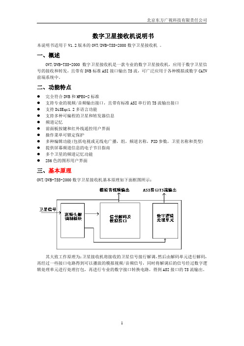
一、概述OVT/DVB-TSS-2000数字卫星接收机是一款专业的数字卫星接收机,应用于数字卫星信号的接收和转发,且带有DVB标准ASI接口输出TS流,可广泛应用于各种模拟或数字CATV 前端系统中。
二、功能特点●完全符合DVB和MPEG-2标准●支持专业的视频/音频输出接口,且带有标准ASI串行的TS流输出接口●支持DiSEqc1.2多语言功能●支持多种可编程的卫星和转发器信息●频道记忆●前面板按键和红外线遥控用户界面●操作菜单可锁定保护●多种编辑功能(包括电视或无线电广播,组,频道名称,PID参数,卫星名称和类型) ●提供屏幕频道信息的电子节目指南●多个卫星的频道记忆功能●256色的图形用户界面三、基本原理OVT/DVB-TSS-2000数字卫星接收机基本原理如下面框图所示:其大致工作原理为:卫星接收机将接收的卫星信号接行解调,然后由解码单元进行解码,再经过一些接口电路得到可以播放的模拟视频/音频信号,同时将解调后的信号经过数字逻辑处理单元进行处理打包,再进行专业的数字接口转换电路,得到ASI接口的TS流输出。
四、产品说明1.1前面板1.电源按键打开或关闭接收机。
2.显示(4位7段数码管)4个数码管显示频道信息。
在休眠模式,显示当地时间。
3.遥控传感器检测遥控器发出的红外信号。
4.CH-/CH+按键在不进入菜单模式时,用于改变频道。
1.2后面板1.TS流输出(ASI OUT)DVB标准ASI接口TS流输出2.高频头输入(LNB IN 13/18V 最大500mA)卫星信号输入口,用同轴电缆连接高频头(LNB)。
3.高频头输出(LNB OUT)卫星信号环出口,可连接其它的卫星信号接收设备。
4.音频输出音频插座提供立体声输出。
5.视频输出视频插座提供一个复合的视频输出。
6.没有使用对于本版本接收机,此接口没有使用。
卫星电视接收调试方法及接收参数
卫星电视接收调试方法及接收参数将天线同轴电缆室内一端英制连接头连接到卫星接收机“天线输入” 连接口上,用随机携带的音/视频线将接收机的“视频”和“左/右音 频”输出端分别与电视机的“视频”和“左/右音频”输入端相连,将电源 线与 220 V/50 Hz 交流电相连后打开接收机电源开关。
带网络接口的卫星电视/数据接收机(RJ-45 接口),还要将网线接 到计算机网卡接口上或交换机上(注:将卫星接收机的配置程序安装 在计算机上,由计算机完成参数配置)。
卫星电视接收机按功能分为两类:一是普通电视接收机;二是电视 /数据接收一体机。
它们的安装与调试方法分别如下:1.普通电视接收机的安装与调试 (1)连接信号线。
第一,连接卫星信号输入:首先检查“射频输入” 连接头是否完好,将同轴电缆线接头接到机器“射频输入”端。
第二, 连接 s 视频端子:用 s 视频线将本机的 s 视频输出端与电视机的 s 视 频输入端相连。
第三,连接音、视频信号:用音、视频线将本机的“L /R”和"VIDEO"分别与电视机的“左/右音频”和“视频”输入端相连。
(2)调试内容和方法。
卫星接收机的调试主要是用遥控器调出配置 “菜单”(MENU),根据菜单的提示,按卫星传输平台提供的卫星参数 将卫星接收机参数配置好,主要参数包括:①根据所要接收的卫星, 设置好卫星接收机所要接收的卫星信号下行频率(中央平台下行频率 为 12 620 MHz,山东平台下行频率为 12 655MHz);②设置好本振 频率(具体情况要看高频头标定的本振频率数值,一般为 11 250 MHz或 11 300 MHz);③设置好下行极化方式(中央平台下行极化方式为 垂直,山东平台下行极化方式为水平);④设置好符号率(中央平台符 号率为 32 553 Ksps,山东平台符号率为 4 340 Ksps);⑤设置好纠 错方式(FEC:3/4 或 AUTO)。
卫星电视接收机的操作指南
各种卫星电视接收机的操作指南1.通过自动搜索功能自动搜索节目以航天珠江WTD-198型卫星接收机为例,其具体操作步骤如下:(1)按遥控器“菜单”键进入“菜单”目录。
(2)在“菜单”目录中选择“系统设置”,按“确认”键。
(3)在“系统设置”目录中选择“恢复出厂设置”,按遥控器“右(?)”键移动到“是”的位置。
(4)出现密码菜单后,按遥控器“上()、下(?)、左(?)、右(?)”(或数字)键,输入“8888”。
(5)按“菜单”键返回主菜单。
(6)在“主菜单”中选择“节目设置”并进入,选择“自动搜索”,再按“确认”键,开始“自动搜台”。
(7)搜台完毕后,按遥控器的“菜单”键退出。
2.通过RS—232串行接口遥控操作3.通过卫星接收机面板(或遥控器)的按键手动操作以科海、亚视达、同州、九州、如意、航天、东仕和长虹公司生产的卫星接收机为例说明此类机型的具体操作步骤。
“科海”卫星接收机具体操作步骤如下:(1)正确调整好卫星天线的方位角、仰角、极化角,并连接好所有设备。
(2)打开卫星接收机电源,按“菜单”键选择“修改本振频率”,再按“确认”键,输入新的本振频率(对于C波段节目为5150MHz; 对于Ku波段节目为11300MHz),按“确认”键确认。
(3)在“菜单”中选择“扩展菜单?节目编辑?增加节目”项。
(4)正确输入节目的“下行频率”、“符号率”和“FEC”参数(其它参数不考虑)。
(5)在“极化方式”选项中,如该节目是“水平极化”就选择“水平极化”,是“垂直极化”就选择“垂直极化”(“H”代表水平极化、“V”代表垂直极化)。
(6)此时,“信号强度”和“信号质量”有百分比显示,并显示“有卫星信号”,或者在接收机面板上,“信号锁定指示灯”为绿色,表示锁定。
(7)按“确认”键,进行节目搜索,系统提示“节目搜索中,请稍候”。
(8)当系统搜到节目并自动存储后,按“菜单”键退出,节目存储完毕。
(9)预搜索新的节目,则按步骤(3)—(8)重复操作即可,需要改变的只是“下行频率”、“符号率”的参数和“极化方式”的选项,直至所有节目搜索完毕。
AOR_ARCC8200_接收机使用手册

RS232 protocol listing for the AR8200 (accompanies the CC8200) Documentation release V1.3Every effort has been made to make this manual correct and up to date. Due to continuous development of the product and by error or omission anomalies may be found and these are acknowledged. This manual is protected by copyright AOR LTD 1998.No information contained in this manual may be copied or transferred by any means without the prior written consent of AOR LTD.AOR and the AOR logo are trade marks of AOR, LTD. All other trade marks and names acknowledged. E&OE.© 1998 AOR LTD. Japan.Index 1General .................................................................12Supplied accessories ............................................13Connection for RS232 operation ..........................14Use of Microsoft Terminal & Hyper Terminal ........25How to send a command ......................................56Command index ....................................................57Detailed command list ...........................................68AOR control software ............................................189Acknowledgements .. (1810)Contact details ......................................................18(1) GeneralThe AR8200 is designed to be connected to a computer using the optional CC8200 lead with built-in level shift conversion, this will enable computer control via the RS232 serial port of a computer. An additional piece of software will usually be required in order to address the computer’s serial port with the correct set of parameters. If using an IBM-PC or clone (with 80386 processor or higher)Microsoft Hyper Terminal (or WINDOWS TERMINAL on Windows 3.1x) may be used to address the computer’s serial port.In order to gain the greatest flexibility, a specialist software package is desirable. For this reason a Windows based PC package is supplied FREE on the CD-ROM accompanying the CC8200 (this may also be made available from the AOR web site ).For those wishing to compile their own software (for computers other than the PC etc) or for basic terminal control, please refer to the following command protocol.(2) Supplied AccessoriesPlease check that the following items are included in the package:CC8200 lead with built-in level shift (9-pin D type connector)One CD-ROM containing protocol listing and PC software One(3) Connection for RS232 operationThe option socket is mounted on the right hand side of the cabinet underneath the 12V d.c. input socket. The socket is protected from dust by a grey rubberised case stopper which is hinged toward the front of the cabinet. Gently lift the stopper from the rear edge to reveal the D-shaped metallic socket. Be careful to keep dust and dirt from this socket and to prevent liquid entering the AR8200 via this socket. Ensure that no conductive material is allowed to short circuit the socket which may damage the receiver.&Notes: Switching the receiver On, setting of volume and adjustment of squelch cannot be achieved via the RS232 port.Computers “always” generate RF noise which may interfere with the AR8200 reception if the standard helical rubber aerial is used.To reduce the effects of noise, use of a remote aerial is highly recommended with good quality 50 OHM coaxial cable employed.The following signals are available via the option socket including detector output, mute and AGC. This pin-out assumes connection using the AOR optional OS8200 or CC8200 leads (refer to page 117 of the English language operating manual):-®&Note:TXD + RXD (levels to drive a level shift converter)The voltage output level to drive external RS232 is deliberately below ‘H’ level. If connecting to an external I.C., you must be aware of latch status.Downloaded byAmateur Radio Directory Connect the optional CC8200 computer control lead to the option socket and connect to a computer.The RS232 parameters may be defined using the CONFIG menu. Baud rates (transfer speed) maybe set to 4800, 9600 or 19200bps. It is also possible to set an ‘address’ to facilitate connection of upto 99 AR8200 to a single port for custom operation, the addresses may be set between the limits of01 to 99 with 00 representing single radio operation.When operating from external RS232, the legend ¤ will be displayed on the LCD. Please refer to page109 section 14-6 of the English language operating manual for information on the CONFIG menu settings.If your computer has a 9-pin ‘D’ type connector then simply connect to the computer’s serial port, if however the computer input is 25 way, either a 9-pin male - 25-way female adaptor (ensure all pins are connected through) or patch lead will be required. If a lead is used, the following connections are suggested:-CC8200 9-pin male PC 25 way female233257 GND7485The following RS232 parameters are employed:-Interface Built in level shift within the CC8200 leadConnections used TXD, RXD, GNDFlow control Software X flowBaud rate19200, 9600, 4800 (selectable)Data8 bit, 2 stop bitsParity NoneRS232 command set ASCII text, <CR> or <CR><LF> delimeter&Note: The ñòïðarrow keys and remote IDcommand (^A) are non-printableBoth the computer and AR8200 must use the same parameters for correct operation. If data is regularly lost or corrupted, try using a slower speed such as 4800 baud. Use of a slower baud rate should not greatly reduce overall communications transfer rate since the processing time within the receiver as PLL lock-time ultimately restricts the whole process.&Note: When changing BAUD rate, switch the AR8200 Off/On to ensure the new speed is selected.(4) Use of Microsoft WINDOWS ‘Terminal’ and ‘HyperTerminal’Windows 3.1x uses TERMINAL in a similar way using TERMINAL in the program Manager group. If the terminal program has not been configured an error message will appear (depending upon the serial port / mouse configuration). Click on [OK] to continue. TERMINAL will open and appear on the screen. You may re-size or maximise the screen at this point. Click on the S ettings heading toward the top of the screen so that the communications and terminal parameters may be configured. Click on “TERMINAL EMULATION” then select “ANSI” then click on [OK]. Click on the S ettings heading toward the top of the screen so that the communications and terminal parameters may be re-configured. Click on “TERMINAL PREFERENCES” then select the required options. Finally click on [OK]. Click on the S ettings heading toward the top of the screen so that the communications and terminal parameters may be re-configured. Click on “COMMUNICATIONS” then select the options as required. The choice of COM port (COM1, COM2 etc) will depend upon your computer serial port and mouse configuration. Finally click on [OK]. Click on theF ile heading toward the top of the screen and select SAVE_AS. This will enable the chosen parameters to be saved in a file which may be OPENED next time TERMINAL is selected so that the parameters will not require future re-configuration (.TRM being the default extension). The file is saved in the main WINDOWS sub directory. For further information regarding WINDOWS TERMINAL and configuration, please refer to the operating manual supplied with Microsoft software and the computer. Click on “COMMUNICATIONS” then select the required options. The choice of COM port (COM1, COM2 etc) will depend upon your computer serial port and mouse configuration. Finally click on [OK].Assuming you have Windows98 loaded on an IBM-PC compatible computer (Windows95 setup is virtually identical) click on the START button:Next scroll up through PROGRAMS, ACCESSORIES, COMMUNICATIONS and onto HYPER TERMINAL (click):The following screen will be displayed:Double click the HYPERTRM.EXE icon, the following screen will be displayed (this may take quite a few seconds as Windows checks your hardware:Enter an identifying name, such as AR8200 then click on OK. The CONNECT TO screen will be displayed:Select the required communications port (serial port). By default, Com1 is selected, this is correct for most lap-top computers but Com2 is more usual for a desktop computer (especially when a serial mouse is used on Com1). Click on OK.Input the required communication parameters as shown above (this example shown 9600 baud but you can select 4800 or 19200), whichever has been configured on in the AR8200 receiver... they MUST be the same. Click on OK .Select the ‘PROPERTIES’ icon (finger pointing at a written page), select ‘SETTINGS’ then click on ‘ACSII Setup ’.Click on the fields indicated to add carriage returns to outgoing and incoming text. Echo displays your keyboard strokes input on to the computer screen. If incoming text is double-spaced, remove the tick box for ‘ASCII Receiving’. Click OK .Refer to the command listings later in this section... to try out the link, ensure that the AR8200 is in 2VFO mode (if not type VA [ENTER] ) then type the command RX [ENTER] via the computer keyboard. The AR8200 should respond with the currentfrequency displayed on the AR8200. To change frequency type RF123 [ENTER], the AR8200 should change to 123.000 MHz.Downloaded byAmateur Radio Directory (5) How to send a commandEach command comprises of two upper case letters (header) along with options as required. All commands use ASCII code which MUST BE IN UPPER CASE (except for the ñòïð arrow keys and remote ID command (^A) which are non-printable and use the control codes of ASCII).A multiple command entry is only valid where specified. Where a multiple command entry is allowed, each command MUST be separated with a space “h20” (HEX DECIMAL). Each command is completed with a [CR] or [CR] [LF]. Although there is no local echo, either [CR] or specified response should come back from the receiver after confirming the correct command.If no response has been gained after a short while, the receiver has failed to receive the command properly. Send a [CR] thenre-send the command. Should problems persist, check your connections and try reducing the RS232 baud rate.AR8200 remote indicationWhen the AR8200 has received a command via the RS232C port the receiver’s LCD will display the symbol. The AR8200 will(6) Command index^A Remote IDAF Automatic Frequency ControlAM Bandscope analyserAP Auto power offAS Search auto storeAT AttenuatorAU Auto modeBM Scan bank linkingBP Search bank protectBS Search bank linkingCF Bandscope centre frequencyCN CTCSS operationDA Dial (VFO) audio squelchDB Dial (VFO) level squelchDC Bandscope date centre frequency DD Dial (VFO) delayDP Dial (VFO) pauseDS Bandscope ****DT Display frequency (on/off)EX Exit RS232GA Select scanGD Release select scan channelsGM Scan parameter selectionGR Select scan recallGS Search parameter selectionGV VFO status listLB LCD contrastLC Frequency & level statusLM Signal meter readingLS Tone eliminator frequency(requires optional TE8200 slot card) MA List a block of memory channels MC Monitor control (forced squelch) MD Receive modeMF Bandscope set marker frequency MP Set memory channel passMQ Delete memory channel or bank MR Memory recallMS Scan modeMW Memory bank resizingMX Memory writeNL Noise limiterOF Frequency offsetOL Set and list frequency offsetOM Opening messagePA Power savePC Protect memory channelPD Delete pass frequencyPH Bandscope peak holdPI Power save interval PP Priority channelPQ Wait time for LC2PR List pass frequenciesPW Write search pass frequencyQM Quick memoryQP Power offQS Delete search bankRF Set receive frequencyRX Respond with current dataSA Search audio squelchSB Search level squelchSC Voice invertor frequency(requires the optional VI8200 slot card) SD Search hold / delay timeSE Set search dataSH Set offset stepSI Voice invertor on/off(requires the optional VI8200 slot card) SL Lower search frequency limitSM Start select scanSP Search pause timeSR Recall search parametersSS Start searchST Tuning step sizeSU Upper search frequency limitSW Bandscope span widthTB Set text description for bankTI Set priority intervalTM Memory textTS Text searchTT Search bank textVA Set VFO AVB Set VFO BVF Select 1-VFO modeVL Beep volumeVR Firmware versionVS VFO searchVT VFO auto-storeVV VFO scanWM Write protect bankWP Write protect enableXA Scan audio squelchXB Scan level squelchXD Memory scan delay timeXM Mode scanXP Scan pause settingUP/DOWN Tuning arrows(7) Detailed command listing for the AR8200^A Remote ID Hex value 0x01Accepts a value nn in the range 01-99AF AFC To set: AF n<CR>n=0 (off), n=1 (on)To read: AF<CR>Response is AF nNote: Not valid in WFM, USB, LSB or CWAM Bandscope Analyser Mode AM<CR> starts bandscope modeAM<CR> repeated when in bandscope mode generates a reportin the following format:AM PH0 CF0091000000 MF0091000000 SW1AP Auto Power off AP nn<CR>nn=00 (off)nn=05-95 (sets 0.5 - 9.5 hours to power off following last active transmission)To read: AP<CR>Responds with AP n.n (where n.n is the delay time in hours or 0.0 = off)Note: nn must be in multiples of 0.5 hoursAS Search auto-store on/off To set: AS n<CR>n=0 (off),n=1 (on - write frequency into bank J),n=2 (on - same as 1 but erase previous channels to create spacefor new entries),To read: AS<CR>Response is either n=0 (off) or n=1 (on)Note: Stores into the search group nominated by GSAT Attenuator To set: AT n<CR>n=0 (off),n=1 (on)To read: AT<CR>Response is AT n, where n=0 (off) or 1 (on)AU Auto mode To set: AU n<CR>n=0 (off), n=1 (on)To read: AU<CR>Response is AU n MD mBM Scan bank link setting To read: BM<CR>Responds with: BM nnnnnnnnnnnnnnnnnnnn,where n = character corresponding to linked bank (A - J or a - j), or - (not linked)Example: BM-BCD---------------- indicates that banks B, C & D are linkedTo set: BM nnnnnnnnnnnnnnnnnnnn<CR>Where n is a character which specifies a bank which will have its link statustoggled (A - J or a - j). There is no need to enter a “-” to avoid changing abank linkBM%%<CR> clears all link settingsBM%% nnnnnnnnnnnnnnnnnnnn<CR> clears all links except those specifiedExamples: BM abc toggles the link status for banks a, b & cBM%% bc clears the link status for all banks except b & cNote: As defined by GM.BP Search Bank Protect To set: BP nn=0 (off), n=1 (on)To read: BP<CR>Response is BN nBS Bank link search To read: BS<CR>Responds with: BS nnn...n, where n = character corresponding to linked bank,or - (not linked). The search bank indicators range from A - T and a - t(40 search banks in all)Example: BS-BC---F-HIJ-------R--a---e--h-j----no---stIndicates that the banks shown are linked.To set: BS nnn...n<CR>Where n is a bank indicator in the range A-T or a-tBS%%<CR> clears all link settingsBS%%nnn...n<CR> clears all link settings except those listedExamples:BSABRabcmp<CR> toggles the link state for the banks shownBS%% BFT<CR> clears all links except for the banks B, F & TNote: As defined by GS.CF Bandscope centre frequency To read: CF<CR>Responds with CF nnnnnnnnnnTo set: CF nnnnnnnnnn<CR> or CF nn.nnnSet the bandscope centre frequency to the specified frequency(expressed in Hz or MHz depending on format)Note: Maximum resolution is 10kHz for spans 10MHz - 500kHz; maximumresolution is 2kHz for spans 200kHz-100kHz. Frequencies below 2kHz arenot accepted.CN CTCSS operation Requires CT8200 optionTo read: CN<CR>Responds with CN nn nn=0 (off), nn=01 (auto), nn=06-37(a frequency from the following table)nn freq nn freq nn freq nn freq00off10136.520241.830177.301auto11141.321250.331183.512146.22267.032189.913151.42371.933196.614156.72474.434199.515162.22577.035206.50694.816167.92679.736229.107100.017173.82782.537254.108103.518179.92885.409107.219186.22988.50A110.91A192.82A91.50B114.81B203.52B97.40C118.81C210.72C69.40D123.01D218.12D159.80E127.31E225.72E165.50F131.81F233.62F171.3To set: CN nn<CR>, where nn is a two digit value from the tableDA Dial (VFO) audio squelch To set: DA nnn<CR>nnn=000 - 255 (where 000=audio squelch off)To read: DA<CR>Responds with DA nnn or DA+nnn (+ = current audio squelch level >= nnn) DB Dial (VFO) level squelch To set: DB nnn<CR>nnn=000 - 255 (where 000=level squelch off)To read: DB<CR>Responds with DB nnn or DB+nnn (+ = current level >= nnn)DC Data centre Frequency To read: DC<CR>Responds with DC nnnExample:DC000Note: Valid only when bandscope is onNote: Refer to the LM commandDD Dial (VFO) delay To set: DD nn<CR>Where nn = 00 - 99 or FF (indicating 0.0 - 99 seconds or FF=hold)To read: DD<CR>Responds with DD n.nDP Dial (VFO) pause To set: DP nn<CR>Where nn = 00 or 01 - 60 (indicating 1 - 60 seconds or off)To read: DP<CR>Responds with DD nnDS Data analysis (bandscope)DS<CR>Responds with wave form data from the bandscope. This is valid only when thebandscope is functioning. Data is output on completion of each sweep over thespan, data is not continuous so response will not be instantaneous.Each datum is assigned a number totalling 1024 with 16HEX.The minimum value of each datum is [2] and maximum [F] by 16HEX.[0] = not measuring, out of span (not 10MHz or 200kHz span).[1] = out of specification of receive frequency.Note: When the span has been narrowed while measuring takes place, only thenewly selected span range will be renewed with fresh data. Care must be takenwhen the marker frequency is replaced with the centre frequency.Example of data analysis response:DS<CR>DS1023: 2222222222222222 2222222222222222DS0991: 2223344433222222 2233322334432233DS0959: 2223AFB722223322 2222354222222233DS0927: 22222222248A9632 2222222498532222DS0895: 2232222456522222 2389A64223344322DS0863: 2222222233343222 2222442222333222~ ~ ~ ~ ~ ~ ~ ~ ~DS0095: C862222552224652 2222235422222222DS0063: 2238B96322255222 2233322233223332DS0031: 23345F9654222222 3334334332222222Note:Data is always sent 32 lines at a time.Frequency is obtained from the data of the centre frequency. Even if the span isselected as 5MHz, 500kHz or 100kHz, the response is always based on 10MHzor 20kHz.When the marker is moved, the data between the centre frequency and the newmarker frequency will be renewed.Frequency data is still obtainable from the centre frequency.Note: When a centre frequency is entered, all figures (numbers) except thesweep range (upper and lower frequencies) will be void.ò centre frequencyDS1023: 2222222222222483 224535AD83332142ñ centre frequencyThere are 1000 pieces of data over a 10MHz span in 10kHz steps, plus 24 piecesin reserve.Note: Data is sent continuously, either buffer memory is required or high speedprocessing is required in order not to miss data.DS0543: 345354339AFD9633 59564323433379ADDS0511: 8634345443369642 2532423333458423ò -10MHzDS0031: 233459A654222222 3334334332222222All figures are data number (marker frequency = centre frequency)Span10MHz5MHz2MHz1MHz50kHzUpper frequency1023800620572545Centre frequency512512512512512Lower frequency12260410442482Each one represents 10kHzSpan200kHz100kHzUpper frequency11892Centre frequency6464Lower frequency0029Each one represents 2kHzDT Display frequency text To set: DT nn=0 (off), n=1 (on)Note: Frequency display is blank when n=1To read: DT<CR>Response is DT nEX Exit RS-232EX<CR>Terminates remote operation via the RS-232 and restores normal operationfrom the radio’s front panel.GA Select Scan on/off To set: GA n<CR>n=0 (off), n=1 (on)GD Release select scan channel To set: GD nn<CR>nn = channel (00-49)To clear all memory select scan settings, use GD%%<CR>To read: GD<CR>Response is GD nnNote: A select scan channel number will be incremented each time select scanchannel has been released. Confirmation is via the GR commandGM Scan parameter selection/status To set: GM n<CR>Tags the current memory with label n = 0 (fixed presets only) - 9 (user definable)To read: GM<CR>Example:GMGM0 XD2.0 XB 000 XA 000 XP00 XMFBM --------------------Note: Refer to individual commands for details of each field.GR Recall tagged channelsfor select scan GR<CR>Lists selected channels from those available for select scan.Response is of the form:GR nn MX mnn RF nnnnnnnnnn ST nnnnnn AU n MD n AT n TM xxxxxxxxxxxNote: Refer to individual commands for details of each field.GS Search parameter selection/status To set: GS n<CR>Where n=0 (fixed presets only) - 9 (user definable)To read: GS<CR>Example:GSGS0 SD2.0 SB 000 SA 000 SP00 AS0BS ----------------------------------------Note: Refer to individual commands for details of each field.GV VFO set list To read: GV<CR>Reads current status of the VFO as a list of parametersExample:GVGV DD0.0 DB 000 DA 000 DP00 VT0Note: Refer to individual commands for details of each field.LB LCD contrast To set: LB nn<CR>nn=00 - 31To read: LB<CR>Responds with LB nnLC Respond with frequencyand level when squelch opens To set: LC n<CR>n=0 (off), n=1 (on), n=2 (special mode)To read: LC<CR>Responds with LC nWhen active, data in the following format is returned when the squelch opens:LC nnn V x RF nnn...norLC nnn SR x RF nnn...norLC nnn M nxx RF nnn...nWhen inactive, the radio returns LC data indicating the end of the transmissionas follows:LC%nnn V xorLC%nnn V xorLC%nnn V xNotes:1. Receive frequency and S-meter level are output when squelch opens (rangeof nnn reported by LC is 120-220 approx but varies from set to set)2. Response is made automatically every time squelch opens or closes and isaffected by squelch parameters such as level and voice scan3. Special mode (LC2) enables a continuous stream of frequency data to beoutput when squelch is open. This allows shift to next frequency after apre-defined delay specified by PQ in search/scan. This also allows for highresolution spectrum analysis.4. Signal level values may be specified 000-255, but only 100-255 is used. TheAGC voltage is processed in 256 steps internally.Note: Refer to individual commands for details of each field.LM Respond with S-meterreading To read: LM<CR>Responds with a 256-level s-meter sample in hexadecimal, LM mnnn,where nnn = 128-256 and m is either “ “ (squelch open) or “%” (squelch closed) LS Tone eliminate frequency Requires TE8200 optionTo set: LS nnn (000-255) (000=off)The following mapping is used between nnn and tone frequency: Tone Freq nnn Tone Freq nnn0.4 (kHz)0-60 2.6 (kHz)230-2350.670-110 3.0237-2401.0160-170 3.4240-2451.4190-200 3.8245-2481.8210-220 4.2248-2502.2220-230To read: LS<CR>Responds with LS nnn or LS+nnn (for mute on)MA List a block of ten memorychannels To read: MA<CR> or MA n<CR> (n= bank A-J or a-j)Example:MAMXA00 MP0 RF010******* ST100000 AU0 MD0 AT0 TMMXA01 MP0 RF0460900000 ST010000 AU0 MD1 AT0 TMTest 2MXA02 MP0 RF0085900000 ST100000 AU0 MD0 AT0 TMTest 3MXA03 MP0 RF0085900000 ST020000 AU0 MD1 AT0 TMTest 4MXA04 MP0 RF0085900000 ST020000 AU0 MD6 AT0 TMTest 5MXA05 MP0 RF0085900000 ST020000 AU0 MD7 AT0 TMTest 6MXA06 MP0 RF0085900000 ST010000 AU0 MD2 AT0 TMTest 7MXA07 MP0 RF0085900000 ST001000 AU0 MD8 AT0 TMTest 8MXA08 MP0 RF0085900000 ST000050 AU0 MD4 AT0 TMTest 9MXA09 MP0 RF0085900000 ST000050 AU0 MD3 AT0 TMTest 10Note: Refer to individual commands for details of each field.MC Monitor Control To set: MC n<CR>0normal squelch operation1squelch forced closed2squelch forced openMD Receive mode To set: MD n<CR>0WFM1NFM2AM3USB4LSB5CW6SFM7WAM8NAMTo read: MD<CR>Responds with mode value as aboveMF Set Marker Frequency To read: MF<CR>Responds with MF nnnnnnnnnnTo set: MF nnnnnnnnnn<CR> or MF nn.nnnSet the bandscope marker frequency to the specified frequency(expressed in Hz or MHz depending on format)Note: Maximum resolution is 10kHz for spans 10MHz - 500kHz; maximumresolution is 2kHz for spans 200kHz-100kHzMP Set memory channel as pass To set: MP n<CR>n = 0 (pass off), n = 1 (pass on)To read: MP<CR> (when in memory read mode)Note: Setting pass on a memory channel excludes it from scansNote: “?” is returned when not in M.RD modeMQ Delete bank or memorychannel MQ<CR>Deletes the current memory channel (when in memory recall mode)MQ nn<CR>Deletes memory channel nnMQ x%%<CR>Deletes all memory channels from bank x.Note: Responds with “?” when a memory channel is protected. Refer to PC, WMand WP commandsMR Recall memory channel MR xnn<CR> recalls memory channel nn from bank x (A-J or a-j)To read the current memory channel: MR<CR>Note: Responds with “?” if the channel is blankMS Scan mode MS<CR>Starts scan using the current memory bankMS x<CR>Starts scan using memory bank x (A-J or a-j)Note: to scan and report active frequencies, see LC commandNote: Responds with “?” if the channel is blankMW Memory Bank resizing MW xnn<CR>Sets number of channels in bank x to nn (where nn=10-90)MW x<CR>Responds with the current allocation for bank x: MW x:nn y:mmExample:MWAMW A:50 a:50MW%%<CR> or MW<CR>Responds with a list of 10 allocationsExample:MW%%MW A:50 TBAAOR TestMW a:50 TBaMW B:50 TBBAOR TestMW b:50 TBbaer bandMW C:50 TBCham callMW c:50 TBcair bandMW D:50 TBDrepeaterMW d:50 TBdaer bandMW E:50 TBEMARINEchMW e:50 TBeair bandNotes:1. This feature allows the size of memory banks to be changed in size from 10 to90 channels. Note, the total number of channels allocated to each bank pair(upper and lower case) remains 100 channels (ie size of A + size of a = 100).2. It takes a significant amount of time to execute this command. Do not attemptto send another command until the radio responds with a <CR>.3.When the size of a bank is changed, any channels that are allocated from thesmaller bank to the larger are erased (ie setting bank B to 80 channels and b to20 channels, then resetting B to 30 channels will cause the last 50 channels of Bto be erased)MX Write data to memory MX xnn RF nnnnnnnnnn AU n ST nnnnnn MD n AT n TM xxxxxxxx<CR>Writes data of the format shown into memory channel nn in bank xFields are separated by a space.TM permits a 12-character alphanumeric ASCII commentAutomode will be selected if any fields are skipped but MX, RF & TM cannotbe skipped. (MX cannot be sent on its own).Note: Refer to the individual commands for further detailsNote: Do not use while scanning or searching.。
卫星电视接收机的操作指南

卫星电视接收机的操作指南各种卫星电视接收机的操作指南1.通过自动搜索功能自动搜索节目以航天珠江WTD-198型卫星接收机为例,其具体操作步骤如下:(1)按遥控器“菜单”键进入“菜单”目录。
(2)在“菜单”目录中选择“系统设置”,按“确认”键。
(3)在“系统设置”目录中选择“恢复出厂设置”,按遥控器“右(?)”键移动到“是”的位置。
(4)出现密码菜单后,按遥控器“上()、下(?)、左(?)、右(?)”(或数字)键,输入“8888”。
(5)按“菜单”键返回主菜单。
(6)在“主菜单”中选择“节目设置”并进入,选择“自动搜索”,再按“确认”键,开始“自动搜台”。
(7)搜台完毕后,按遥控器的“菜单”键退出。
2.通过RS—232串行接口遥控操作3.通过卫星接收机面板(或遥控器)的按键手动操作以科海、亚视达、同州、九州、如意、航天、东仕和长虹公司生产的卫星接收机为例说明此类机型的具体操作步骤。
“科海”卫星接收机具体操作步骤如下:(1)正确调整好卫星天线的方位角、仰角、极化角,并连接好所有设备。
(2)打开卫星接收机电源,按“菜单”键选择“修改本振频率”,再按“确认”键,输入新的本振频率(对于C波段节目为5150MHz; 对于Ku波段节目为11300MHz),按“确认”键确认。
(3)在“菜单”中选择“扩展菜单?节目编辑?增加节目”项。
(4)正确输入节目的“下行频率”、“符号率”和“FEC”参数(其它参数不考虑)。
(5)在“极化方式”选项中,如该节目是“水平极化”就选择“水平极化”,是“垂直极化”就选择“垂直极化”(“H”代表水平极化、“V”代表垂直极化)。
(6)此时,“信号强度”和“信号质量”有百分比显示,并显示“有卫星信号”,或者在接收机面板上,“信号锁定指示灯”为绿色,表示锁定。
(7)按“确认”键,进行节目搜索,系统提示“节目搜索中,请稍候”。
(8)当系统搜到节目并自动存储后,按“菜单”键退出,节目存储完毕。
卫星电视接收调试方法及接收参数

卫星电视接收调试方法及接收参数The manuscript was revised on the evening of 2021卫星电视接收调试方法及接收参数将天线同轴电缆室内一端英制连接头连接到卫星接收机“天线输入”连接口上,用随机携带的音/视频线将接收机的“视频”和“左/右音频”输出端分别与电视机的“视频”和“左/右音频”输入端相连,将电源线与220 V/50 Hz交流电相连后打开接收机电源开关。
带网络接口的卫星电视/数据接收机(RJ-45接口),还要将网线接到计算机网卡接口上或交换机上(注:将卫星接收机的配置程序安装在计算机上,由计算机完成参数配置)。
卫星电视接收机按功能分为两类:一是普通电视接收机;二是电视/数据接收一体机。
它们的安装与调试方法分别如下:1.普通电视接收机的安装与调试(1)连接信号线。
第一,连接卫星信号输入:首先检查“射频输入”连接头是否完好,将同轴电缆线接头接到机器“射频输入”端。
第二,连接s视频端子:用s 视频线将本机的s视频输出端与电视机的s视频输入端相连。
第三,连接音、视频信号:用音、视频线将本机的“L/R”和"VIDEO"分别与电视机的“左/右音频”和“视频”输入端相连。
(2)调试内容和方法。
卫星接收机的调试主要是用遥控器调出配置“菜单”(MENU),根据菜单的提示,按卫星传输平台提供的卫星参数将卫星接收机参数配置好,主要参数包括:①根据所要接收的卫星,设置好卫星接收机所要接收的卫星信号下行频率(中央平台下行频率为12 620 MHz,山东平台下行频率为12 655MHz);②设置好本振频率(具体情况要看高频头标定的本振频率数值,一般为11 250 MHz或11 300 MHz);③设置好下行极化方式(中央平台下行极化方式为垂直,山东平台下行极化方式为水平);④设置好符号率(中央平台符号率为32 553 Ksps,山东平台符号率为4 340 Ksps);⑤设置好纠错方式(FEC:3/4或AUTO)。
如何接收和调试卫星电视节目
如何接收和调试卫星电视节目接收和调试卫星电视节目是一项涉及到卫星信号接收、天线安装调试及电视信号处理等多方面知识和技术的任务,下面将具体介绍如何接收和调试卫星电视节目。
1.硬件准备:首先需要准备必要的硬件设备,包括卫星电视接收器、卫星天线、卫星电视调试仪/电视分析仪、电视以及相关电缆和连接器等。
确保设备是正规品牌、有保修和售后服务,以及符合本地的技术标准和法规。
2.天线安装:选择一个合适的位置安装卫星天线,确保能够充分接收到卫星信号。
天线的安装最好处于开阔且无障碍物的地方,远离高压电线、电视台和速度较快的车辆等可能导致信号干扰的因素。
使用正确尺寸和规格的天线支架将卫星天线固定在房顶、阳台或者墙壁上。
3.调试天线:调试天线将会涉及到定位、方位角和仰角的调整。
可以参考卫星电视节目供应商提供的手册或者网站的相关信息,找到卫星的位置和角度信息。
使用仰角和方位角的相乘关系以及指南针等工具来调整卫星天线的方向,确保对准卫星信号的发射源。
定位好后,使用电视上的信号质量和电平检测功能进行细调,确保接收到稳定的信号。
4.连接电缆:将卫星天线通过合适的电缆连接到卫星接收器的接收接口上。
根据接收器的说明书或者界面提示,正确连接电缆,确保连接紧固且没有松动。
注意使用合适质量的电缆和连接器,以确保信号传输的质量和稳定性。
5.电视设置和频道:将卫星接收器和电视通过HDMI、AV或者其他适配器连接线连接好,并确保连接正常。
电视打开后,进入菜单设置中的信号源选项,将信号源切换到卫星接收器的输入,然后在卫星接收器的菜单中进行频道和节目调试。
根据接收器的提示,选择正确的卫星名称和频率范围等参数,进行和存储。
6.信号调试:在完成频道后,使用卫星电视调试仪或电视分析仪来调试信号。
这些设备将会提供更加详细的信号质量和电平信息,包括信号强度、信噪比、载波误差和位错等。
通过观察这些指标,可以进行调整和优化,以获得更好的图像和音频质量。
7.调试节目:综上所述,接收和调试卫星电视节目需要正确安装和调试卫星天线,合理设置和连接硬件设备,调试信号的质量和参数,并确定节目能够正常播放和显示。