51温控系统说明书
51温度控制系统
基于51单片机的温度控制系统王鹏魏宗乐李贝贝一、摘要单片机的应用正在不断地走向深入,同时带动传统控制检测日新月益更新。
在实时检测和自动控制的单片机应用系统中,单片机往往是作为一个核心部件来使用,仅单片机方面知识是不够的,还应根据具体硬件结构,以及针对具体应用对象特点的软件结合,加以完善。
DS18B20是美国DALLAS公司生产的数字温度传感器芯片,具有结构简单、体积小、功耗小、抗干扰能力强、使用方便等优点。
本文设计的一种温度控制系统,用STC89C52单片机作为温控器,选用DS18B20数字温度传感器,可任意设置上下限报警温度,采用数码管实时显示温度。
二、关键词STC89C52单片机、上下限报警、数码管显示温度三、正文3.1. 设计目的(1) 了解电子系统的设计方法,巩固和提高学过的基础理论和专业知识;(2) 学习DS18B20数字温度传感器的测温原理,提高运用所学专业知识进行独立思考和综合分析、解决实际问题的能力;(3) 增强对单片机的认识,掌握分析处理问题的方法,进行调试、计算等基本技能的训练,达到具有一定程度的实际工作能力。
3.2 •具体内容及要求用单片机为主控制器,设计以温度控制系统。
(1 )基本要求①实现0-99 C范围内的温度检测,精度 1.0级。
②通过两位LED显示器显示被测温度值。
③可通过按键设置温度报警值,并在LED上进行显示。
(2 )发挥部分①增加报警功能,当被测温度超过报警限时,发出声音报警。
②将精度改进为0.1级。
3.3系统总体方案设计3.3.1、设计方案论证由于本设计是测温电路,可以使用热敏电阻之类的器件利用其感温效应,在将随被测温度变化的电压或电流采集过来,进行A/D转换后,就可以用单片机进行数据的处理,在显示电路上,就可以将被测温度显示出来,这种设计需要用到A/D转换电路,其中还涉及到电阻与温度的对应值的计算,感温电路比较麻烦。
而且在对采集的信号进行放大时容易受温度的影响出现较大的偏差。
基于51单片机和PID的恒温控制系统设计说明
摘 要工业生产中温度控制具有单向性、时滞性、大惯性和时变性的特征,要实现温度控制的快速性和准确性,对于提高产品质量具有很重要的现实意义。
本课题针对温度控制的特点与实现准确温度控制的意义,设计了一种基于PID 的恒温控制系统。
设计容包括硬件和软件两个部分。
硬件电路以AT89S52单片机为微处理器,详细设计了为单片机提供电的电源电路,温度信号采样电路,键盘与显示电路,加温控制电路等四大电路模块。
软件部分主要对PID 算法进行了数学建模和编程。
PID 参数整定采用的是归一参数整定法。
本设计由键盘电路输入设定温度信号给单片机,温度信号采集电路采集现场温度信号给单片机,单片机根据输入与反馈信号的偏差进行PID 计算,输出控制信号给加温控制电路,实现加温和停止。
显示电路实现现场温度的实时监控。
本系统PID 参数整定在MATLAB 软件下SIMULINK 环境中进行了仿真,通过稳定边界法整定得到P K 、D K 、I K 参数,最终系统无稳态误差,调节时间为30s ,无超调量,各项指标均满足设计要求。
本系统实现简单,硬件要求不高,且能对温度进行时实显示,具有控制过程的特殊性,本设计提出了一种基于PID 算法来实现恒温控制的温度控制系统,主要是为了达到生产过程中对温度控制速度快,准确性高等特点。
关键词:恒温控制,单片机,PID 算法,MATLAB 仿真ABSTRACTIndustrial production is a one-way temperature control, delay, the inertia and time-varying characteristics, To achieve the rapid temperature control and accuracy, improving the quality of products is a very important practical significance.The temperature control issues against the characteristics and achieve precise control of temperature, Based on the design of a PID temperature control system. Design elements include hardware and software in two parts. Hardware circuit to AT89S52 MCU for microprocessors, for the detailed design of the microcontroller to provide electricity supply circuit, Temperature signal sampling circuit, keyboard and display circuits, such as heating control circuit four circuit module. Software major part of the PID algorithm is a mathematical modeling and programming. PID tuning parameters are used to a fixed parameter. The circuit design of the keyboard input from the set temperature signal to the microcontroller, Temperature Signal Acquisition Circuit collect temperature signal to the microcontroller, According to SCM input and feedback signal, the error for PID, the output control signals to the heating control circuit, Heating and achieve stop. Show circuit scene of the real-time monitoring of temperature.The system PID tuning parameters in MATLAB software under SIMULINK environment for the conduct of the simulation, By stabilizing the border will be the entire law, and parameters, the end system without steady-state error and adjust to the 30's, no overshoot, all targets were met design requirements. The system is simple, and hardware, but also the real-time temperature, with the particularity of the control process, The design of a PID algorithm based on the temperature control to achieve the temperature control system, the main aim is to achieve the production process for the temperature control speed, high accuracy.Keywords:Temperature control, microcontroller, PID algorithm, MATLAB目录第1章绪论 (1)1.1 引言 (1)1.2方案论证 (3)1.2.1 方案一利用单片机实现恒温控制系统 (3)1.2.2方案二利用PLC实现恒温控制系统 (4)1.2.3方案三利用模拟PID调节实现恒温控制系统 (4)1.3 设计方案 (5)第2章恒温控制系统硬件设计62.1AT89S52单片机简介 (6)2.1.1AT89S52单片机资源简介 (6)2.1.2AT89S52单片机信号引脚介绍 (7)2.1.3AT89S52单片机的时钟电路和复位电路 (8)2.2 温度传感器 (9)2.3 电源电路 (10)2.3.1电源变压器 (10)2.3.2 整流滤波电路 (10)2.3.3 稳压电路 (10)2.4 键盘和显示电路 (12)2.5 加温控制电路 (13)2.6 与上位机通讯 (14)第3章恒温控制系统软件设计143.1PID调节器控制原理 (14)3.2 位置式PID算法 (15)3.3数字PID参数整定 (15)3.3.1 采样周期的选择 (16)3.3.2PID参数对系统性能的影响 (17)3.4PID计算程序 (18)第4章 MATLAB仿真 (29)4.1 SIMULINK简介 (29)4.2 系统仿真方框图 (30)4.3稳定边界法整定PID参数 (30)结论 (35)参考文献 (36)致 (37)附录38第1章绪论1.1 引言电加热温度控制具有升温单向性、大惯性、大滞后性和时变性的特点。
Nailor CTE-5100系列温控器操作手册说明书
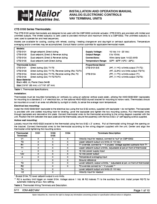
INSTALLATION AND OPERATION MANUALANALOG ELECTRONIC CONTROLSVAV TERMINAL UNITSCTE-5100 Series Thermostats:The CTE-5100 series thermostats are designed to be used with the CSP-5002 controller actuator. CTE-5100’s are provided with limited and unlimited outputs. The limited output(s) is (are) used to provided minimum and maximum limits to a CSP-5002. The unlimited output(s) is (are) used to operate fan and heat sequences.Models are available for cooling, cooling with reheat, cooling / heating changeover and day/night or set-back applications. Temperature averaging and/or overrides may be accomplished. Consult Nailor control submittal for applicable thermostat model.Models:CTE-5101Single setpoint; Direct Acting Supply Voltage:16 Vdc (14 - 20 Vdc)CTE-5103Dual setpoint; Direct & Reverse Acting Output Range:0 to 10VdcCTE-5104Dual setpoint; Direct & Reverse Acting Connections:Wire clamp type: 14-22 AWGCTE-5105Dual setpoint; both Direct Acting Temperature Range:55O F - 85O F (13O C - 29O C)Thermostat Action:Proportional Band:CTE-5101Direct Acting (DA) T1/T3CTE-5101/3/52O F, (1.1O C) w/limits output (T1/T2)CTE-5103Direct Acting (DA) T1/T3, Reverse Acting (RA) T2/T44O F, (2.2O C) w/o limits output (T3/T4) CTE-5104Direct Acting (DA) T1/T3, Reverse Acting (RA) T2CTE-51042O F, (1.1O C) w/limits output (T1)CTE-5105Direct Acting (DA) T1/T2/T3/T42O F, (1.1O C) w/limits output (T2/T3)Base Material:Black ABS, UL Flame Class 94HBSize2 9/16" (65 mm) x 3 7/16" (87 mm)Table 1.Thermostat Specifications.Installation:Thermostats must be mounted horizontally,(or vertically by using an optional vertical scale plate), utilizing the HMO-5030/5031 backplates for mounting to a standard 2" x 4" electrical box, or the optional HMO-5023 drywall bracket for mounting to hollow walls. Thermostats should be mounted on a wall in an area not affected by sunlight or drafts, to sense the average room temperature.Electrical box mounting:Install the HMO-5030/5031 backplate to the electrical box using the two 6-32 screws, supplied with backplate – do not tighten. The backplate is provided with one slotted mounting hole for leveling. Level the backplate and tighten the two mounting screws. Pull thermostat wires through backplate and decorative trim plate. Connect thermostat wires to the thermostat according to the wiring diagram supplied with the unit. Position the trim between the back plate and the thermostat, secure the assembly with the two 6-32 x 2" self tapping screws supplied. Hollow wall mounting:Loosely mount the HMO-5023 bracket to the thermostat using the two 6-32 x 2" screws. Pull all thermostat wiring through the opening on the bracket. Connect thermostat wires to the thermostat according to the wiring diagram supplied with the unit. Center and align the thermostat while tightening the mounting screws.Thermostat510151035104Terminals DescriptionTerminals5105V1X X X Velocity input for readout, connect to “out” on CSP-5002T3X X X Upper setpoint output w/o limits (0 -10 Vdc)R1X X X T1 override, connect to "-" if unused. Voltage applied subtracts from T1 T1X X X Upper setpoint output w/limits. Adjustable at pot.on front of thermostat +X X X16 Vdc power supply input12V X X X12 Vdc power outputA X X X Temperature averaging input-X X X Ground referenceT2X X Lower setpoint, output w/limits. * Adjustable at pot. on front of thermostat R2X X T2 override connect to "-" if unused **T4X Lower setpoint output w/o limits (0 -10 Vdc)V2X Velocity input for readout* Except 5104; T2 lower setpoint output is w/o limits.** R2 is auxiliary limit trigger on model 5104. Voltage above 1 Vdc @ R2 indexes T1 to the auxiliary flow limit. Install jumper R2-T2 for automatic indexing of aux. flow setting.Table 2.Thermostat Wiring Terminals and Description.Figure 1. Thermostat Detail Maintenance:No routine maintenance is required. Each component’s design and material selection assures dependable long-term reliability and performance. Careful installation will also enhance long term reliability and performance.CSP-5002 DAMPER CONTROLLER/ACTUATORAll Nailor standard right hand (and optional left hand) terminal units have a 1/2" (13), diameter drive shaft and a clockwise to close damper rotation (Dual Duct Left Hand Deck CCW to close). Full damper shaft rotation is 45 or 90 degrees depending on model. The CSP-5002should be mounted on the damper drive shaft so the actuator will stall at either end of the stroke to ensure tight shut-offs and full rotation.Ensure the two jumpers are set for the correct damper rotation.The CSP-5002 has a tri-color LED that indicates the current action of the damper: RED – Closing, GREEN – Opening, WHITE – Satisfied.The CSP-5002 provides pressure independent VAV control for terminal unit primary valves. Primary air volume is monitored by the use of a multi-point flow sensor located in the inlet duct. Differential pressure is measured by an onboard platinum transducer. The changes in the inlet static pressure will vary the position of the inlet damper. Flow limit adjustments are made using a digital DC voltmeter at the thermostat.The CSP-5002 is factory calibrated with VNOM adjustment centered for the enclosed voltage - airflow charts. Do not adjust. Dampers are always shipped in the full open position.(WHERE APPLICABLE)ACESS DOOR GEAR DISENGAGEMENT BUTTONP PORTS 3/16" (5) DIA. (2)Figure 2. CSP-5002 Controller / ActuatorPOWER REQUIREMENTS:Controller / actuator / thermostat is 7VA plus any output loads for fan relays, heating contactors and control valves (assume 10 VA each).Always switch control voltage off prior to disconnecting any wires from the controller.ANALOG CONTROL CALIBRATION CHARTS VOLTAGE VS. AIRFLOWWhen field adjustment or field calibration of the CTE-5100 series thermostats is necessary, desired limit control can be calculated using the tables in Figure 3 and the following formulas, or the charts presented in Figures 4 through 8.Formulas:CFM = K (VDC - Offset)VDC = (CFM/K) + Offset Follow the individual calibration procedure for the thermostat model(s) as required.Inlet sizeK factorOffset14 x 10417- 0.1424 x 161250- 0.07Inlet sizeK factorOffset4 in. Round 33+ 0.445 in. Round 55+ 0.026 in. Round 75+ 0.087 in. Round 115- 0.198 in. Round 143+ 0.329 in. Round 175+ 0.1010 in. Round 233+ 0.0912 in. Round 357- 0.0414 in. Round 500- 0.0716 in. Round625- 0.25Inlet sizeK factorOffset12 in. Oval 333- 0.2214 in. Oval 417- 0.4716 in. Oval 588+ 0.0518 in. Oval759- 0.27Figure 3.Diamond Flow Sensor K Factors.2.03.04.05.06.07.01.0V O L T S , D C100200300400600500AIRFLOW,CFMFigure 4.Inlet Sizes 4, 5, 6 Round2.03.04.05.06.07.08.01.0V O L T S , D C100200300400600500800700900110010001200140013001500AIRFLOW,CFMFigure 5.Inlet Sizes 7, 8, 9, 10 Round2.03.04.05.06.07.01.0V O L T S , D C5001500100025002000300040003500AIRFLOW,CFMFigure 6.Inlet Sizes 12, 14, 16 Round. 14 x 10 Rectangular02.03.04.05.06.07.01.0V O L T S , D C5001500100025002000300040003500AIRFLOW,CFMFigure 7.Inlet Sizes 12, 14, 16 Oval (Single Duct Only)02.03.04.05.06.07.01.0V O L T S , D C500150010002500200030004000350045005500500060006500700080007500AIRFLOW,CFMFigure 8.Inlet Size 18 Oval. 24 x 16 RectangularCALIBRATION PROCEDURE FOR AIR VOLUME ADJUSTMENTS MADE AT THERMOSTATThermostats are factory calibrated when minimum and maximum airflow limits are provided. Field calibrations are as follows:Minimum and maximum setpoints (air volume limits), are set at the thermostat. Check the CSP-5002 controller to ensure that the minimum and maximum potentiometers are dialed completely out (min. CCW, max. CW), so that the thermostat signal is not restricted.A – Required Tools:1. Small flat blade screwdriver 1/8" / 3 mm 3. Hex Wrench 1/16" / 2mm for the cover screws2. Digital voltmeter w/DC range to hundredths 4. A test lead (HSO-5001) is recommended for meter readingsB – Remove Thermostat Cover:Thermostat cover is removed by turning the two set screws CW, (which are located on the short sides of the thermostat). Remove cover and setpoint slider stops if installed.Figure 9.Thermostat scaleplate detail.CTE – 5101 SINGLE SETPOINT THERMOSTAT(DA T1 with limits, T3 without limits)1. Ambient temperature at the thermostat must be between 55O F – 85O F (13O C – 29O C).2.Adjust the setpoint slider all the way to the right for minimum cooling. Connect voltmeter to the cooling (right side) voltmeter taps. The center and right tap provide the VDC readings (min/max airflow). The center and left tap provide the actual air volume (live velocity)reading when thermostat V1, is connected to the controller OUT terminal.3.Read the VDC across the taps. Adjust the MIN INCR potentiometer to the VDC equal to the desired air volume as shown on the chart.NOTE: The minimum setpoint must be set first. Adjustment of the minimum potentiometer directly affects the maximum setpoint.4.Adjust the setpoint slider all the way to the left for maximum cooling.5.Read the VDC across the taps. Adjust the MAX INCR potentiometer to the VDC equal to the desired air volume as shown on the chart.NOTE: The maximum setpoint must be set last. Adjustment of the minimum potentiometer directly affects the maximum setpoint.6.Return the setpoint slider to the desired setpoint. Install the optional setpoint stops if required and replace thermostat cover.CTE - 5103 DUAL SETPOINT THERMOSTAT (Heat / Cool Changeover)(DA T1/T3. RA T2/T4. T1, T2 with limits, T3, T4 without limits)Cooling side of thermostat1.Follow steps 1 through 5 for the CTE-5101 thermostat. Note: Be sure to adjust the cooling setpoint slider all the way to the left for maximum cooling. (The heating setpoint sider will have to be adjustable all the way to the left also).Heating side of thermostat1.Ambient temperature at the thermostat must be between 55O F - 85O F (13O C - 29O C).2.Adjust the heating setpoint slider all the way to the left for minimum heating. Connect voltmeter to the heating (left side) voltmeter taps.The center and right tap provides the VDC readings (min/max airflow).3.Read the VDC across the taps. Adjust the MIN INCR potentiometer to the VDC equal to the desired air volume as shown on the chart.NOTE: The minimum setpoint must be set first. Adjustment of the minimum potentiometer directly affects the maximum setpoint.4.Adjust the heating slider all the way to the right for maximum heating.5.Read the VDC across the taps. Adjust the MAX INCR potentiometer to the VDC equal to the desired air volume as shown on the provided chart.NOTE: The minimum setpoint must be set first. Adjustment of the minimum potentiometer directly affects the maximum setpoint.6.Return both setpoint sliders to the desired setpoints. Install the optional setpoint stops if required and replace thermostat cover.SCALE PLATE (°F OR °C)METER TAPCTE – 5104 DUAL SETPOINT THERMOSTAT(DA T1/T3. RA T2. T1 with limits, T2, T3 without limits)Cooling side of the thermostat1.Follow steps 1 through 5 for the CTE-5101 single setpoint thermostat. Note: Be sure to adjust the cooling setpoint slider all the way to the left for maximum cooling. (the heating setpoint slider will have to be adjustable all the way to the left also).Adjustment of the Auxiliary Setpoint - Higher reheat minimum (if required).2.Read the VDC across the meter taps on the heating (left) side of the thermostat. With the left hand slider in the full heat position,completely to the right, adust the MAX/AUX INCR potentiometer to the VDC equal to the desired air volume as shown on the chart. If a higher Aux Min is not required, dial fully CCW.3.Return both setpoint sliders to the desired setpoints. Install the optional setpoint stops if required and replace thermostat cover.CTE – 5105 DAY / NIGHT THERMOSTAT (Night Temperature Set Back)(DA T1/T2/T3/T4. T1/T2 with limits, T3/T4 without limits)Day side of thermostat1.Follow steps 1 through 5 for the CTE-5101 thermostat.Note: Be sure to adjust the day setpoint slider all the way to the left for maximum cooling. The night setpoint slider will have to be adjusted all the way to the left also.2.Return both setpoint sliders to the desired setpoints. Install the optional setpoint stops if required and replace thermostat cover.Night side of thermostat1.Follow steps 1 through 5 for the CTE-501 thermostat.Note: Be sure to adjust the night setpoint slider all the way to the right for minimum cooling. The day setpoint slider will have to be adjusted all the way to the right also.2.Return both setpoint sliders to their desired setpoints. Install the optional setpoint stops if required and replace thermostat cover.Figure 10.Thermostat action schematics.-2F Dir. Act. S.P . +2F -2F Dir. Act. S.P .+2F(Night) (Day)-2F Rev. Act. S.P .+2F -2F Dir. Act. S.P .+2F(Heating) (Cooling)CTE-5105 Thermostat-2F Rev. Act S.P. Dir. Act. S.P. +2F(Heating) (Cooling)CTE-5104 Thermostat V D C O u t p u t-2F S.P . +2FCTE-5101 Thermostat V D C O u t p u tCTE-5103 ThermostatV D C O u t p u tV D C O u t p u tGENERAL INFORMATION FOR ALL TERMINAL UNITSCheckout ProcedureThe CSP-5002 actuator will take up to 2.5 minutes for a 45 degree stroke damper and up to 5.0 minutes for a 90 degree stroke damper to cycle from its minimum to its maximum setting and vice versa. It is important therefore when verifying minimum and maximum flow limits, by moving the slider(s) right or left as previously described, to wait sufficient time to ensure the actuator has moved to its correct position and that the live velocity read-out (if used) has settled.Live Supply Volume ReadoutA voltage output corresponding to actual primary air volume may be monitored at the room thermostat to assist in balancing and troubleshooting. The output signal is the same as the airflow volume vs. DC voltage calibration curve. The test lead (HSO-5001) is connected to the innermost meter taps on the thermostat scaleplate (see Figure 9).Supply Air Temperature SensingA duct mounted temperature sensor (thermistor) is used to measure primary air temperature in control sequences involving automatic changeover (ACO) or morning warm-up (MWU). The probe is attached to the inlet collar and wired to the low voltage controls enclosure. To ensure proper operation for auto changeover, a minimum flow setting should be used for both heating and cooling modes. This allows airflow to constantly pass over the duct temperature sensor.Proportional Reheat ControlHot water valves and SCR controllers with a 0 -10 Vdc control signal (10mA max,) are wired (+) to terminal ‘T2’ on the thermostat and (-) to the grounded side of the low voltage control circuit. T2 is an output with limits and it must therefore be ensured that the thermostat limits are dialed out (max. pot. fully CW and min. pot fully CCW) for unrestricted operation.FAN POWERED TERMINAL UNITSNight Shut DownUnits ordered with optional Night Shut Down (NSD) sequences employ an airflow switch to sense when primary air has been shut down. When the airflow switch opens the fan and optional heat are shut down. Upon the primary air starting, the airflow switch will close and return the unit to normal operation.Night Temperature SetbackUnits ordered with optional Night Temperature Setback (NTSB) sequences employ an airflow switch to sense when the primary air (central air handler) has been shut down. When the airflow switch opens, a lower night time temperature setpoint is initiated. The unit fan and optional supplementary heat will cycle intermittently to maintain night setpoint temperature. Upon start up of the central air handler, the unit will return to daytime operation. Amount of setback is either fixed or adjustable dependent on control sequence. Refer to control submittal. Night CycleOn series units with optional night cycle sequences, an airflow switch de-energizes unit fan upon loss of primary (central system) air. Upon a call for heat, the thermostat will override the airflow switch and cycle the unit fan followed by any supplementary heat intermittently to maintain day setpoint temperature.On parallel units, basic control sequences cycle the fan and supplementary heat intermittently as standard in response to thermostat demand. This will therefore still occur at night when the central air has been shutdown.Checkout Procedure (Day / Occupied Mode)Series Fan Powered Terminal Units: The fan should be energized regardless of slider(s) position. Dependent on control sequence ordered, thermostat may have one or two sliders. Consult control sequence submittal / wiring diagram and thermostat calibration procedure.Parallel Fan Powered Terminal Units: Fan will only cycle upon a call for heat. Move single slider (or both if a separate heating or night slider is present) full right to energize fan. Dependent on control sequence ordered, thermostat may have one or two sliders. Consult control sequence submittal / wiring diagram and thermostat calibration procedure.Checkout Procedure (Night / Unoccupied Mode)Move thermostat slider(s) full right to energize fan and supplementary heat.TROUBLESHOOTING PROCEDURENote: Turn off power before making any wiring changes to the unit.1. Verify 24 Vac at CSP-5002 controller / actuator terminals "~" (phase) and "-"(ground). Tolerance +20 / -15% (20.4-28.8 Vac). When using a common transformer for more than one CSP-5002, polarity should be observed.2. Check correct field wiring from thermostat to terminal block in unit low voltage enclosure. Refer to Nailor control wiring diagram inside controls enclosure. Ensure all wiring connections are tight and secure.3. Check tubing from unit inlet flow sensor to the controller / actuator is correct and no leaks. "Hi" side of sensor to "H" on controller / actuator and "Lo" side of sensor to "L" on controller / actuator.4. Verify 16 Vdc at CSP-5002 terminals "16 VDC" and "-". Tolerance is 15 to 17 Vdc power supply to thermostat. If not correct, disconnect thermostat and recheck. If still incorrect, replace CSP-5002 controller / actuator.5. Check requested minimum and maximum flow settings on terminals "IN" and "-". Refer to Vdc vs. Airflow setting charts at back of this document. If reading is not what is desired, refer to thermostat calibration procedure.6. Check actual airflow (live velocity readout) voltage on terminal "OUT" and "-" (0 – 10 Vdc). Use calibration charts provided.7. Check for damper movement and correct rotation.a) Review "requested flow" and actual flow" above to determine if unit should be satisfied (within 50 fpm +/- 0.20 Vdc) or driving damper open or closed.b) If damper is not moving, verify damper is not stuck at end of travel and has free movement. Use manual release clutch on CSP-5002.Check CW / CCW rotation jumpers for proper operation. Ensure damper actuator connection is correct and damper can travel fully open to fully closed within limits of the actuator stroke. Check actuator coupling to damper shaft setscrews are tight.c) Change "requested flow" to make unit drive opposite direction (verifying correct damper movement). This can be accomplished by moving thermostat setpoint sliders or:i) To manually open damper, remove wire from terminal "IN" and jumper terminal "IN" to 16Vdc". This will tell unit to control at full airflow and the green LED should turn on, driving damper fully open.ii) To manually close damper, remove wire from terminal "IN" and jumper terminal "IN" to "-" terminal. This will tell unit to control at zero airflow and the red LED should be on, driving damper fully closed.Warning:Never jumper terminal "16 Vdc" to "-", as this will cause short and possibly damage the power supply.REE – 5002 Relay Module Fan with 2 Stage ReheatThe REE-5002 is used in all parallel flow terminal units, and specific series flow terminal units with the night cycle or setback options. The relay cycles the fan and activates up to 2 stages of heat in response to a direct acting 0 -10 Vdc thermostat output. The fan start point is adjustable from 3-8 Vdc which equates to -0.8 to +1.2O F,(-0.4 to +0.7O C), around setpoint. The factory setting is 4 Vdc (-0.4F below cooling setpoint / min. primary airflow setting). To field adjust, read the Vdc across terminals "X" and "-". Adjust the potentiometer to Vdc desired setpoint. The two stages of heat are sequenced to energize after the fan is activated when the desired room temperature continues to decrease.CSP-5001CONTROLLER-ACUATORFigure 11.Ree-5002 Relay Module. Fan with 2 stage reheat.THERMOSTAT SIGNAL (T3)(1 VDC SWITCHING DIFFERENTIAL)S TA GE SFAN 1 1 3 8 VOLTS 2DESCRIPTIONVENDOR PART NO.NAILOR PART NO.KMC Controller / Actuator CSP-5002V3004(Kreuter)Controller / Actuator CSP-4606V3005Controller / ActuatorCSP-4616V3006In-line filter for CSP-4XXXHFO-0034V3007KMC (Kreuter) Room Thermostat and accessories:CTE-5100 Series - (0 -10 Vdc):DA clg. (base only)CTE-5101V3030DA clg. / RA htg. (base only)CTE-5103V3031DA clg./RA reheat (base only)CTE-5104V3032DA / DA (Day / Night) (base only)CTE-5105V3033Accessories for CTE-5100 Series:Thermostat Cover - light almondHPO-1511V1060- WhiteHPO-1512V1061Backplate mounting kit(for mounting to a 2 x 4 handy box) - light alomdHMO-5024V1062- WhiteHMO-5026V1063Mounting Strap kit (for mounting on holllow wall)HMO-5023V1064Horizontal Scale Plate - O FHPO-0060-10V1069- O CHPO-0060-11V1070Miscellaneous:KMC Electric reheat relay module, 3 stage REE-5001V3050KMC Wet heat time prop. relay module DA/NC valve REE-5106V3053RA/NO valve REE-5123V3054KMC Fan/elec. heat relay module, 2 stage REE-5002V3055KMC Fan/wet heat time prop. relay moduleDA/NC valve REE-5017V3056RA/NO valveREE-5024V3057KMC Constant volume relay module REE-1004V3058KMC Heat / Cool changeover moduleREE-1005V3059KMCDuct temp. changeover sensor (for use with REE-1005)STE-1002V3060Airflow Switch FS-BO-182V3061DPDT Relay 24V.9100-233Q323V3062Transformers (foot mount):120to 24 V. 40 VA -VH1-669120to 24 V. 50 VA -VH1-692208/240to 24 V. 40 VA -VH1-670208/240to 24 V. 50 VA -VH1-685277to 24 V. 40 VA -VH1-675277to 24 V. 50 VA -VH1-674277to 24 V. 75 VA -VH1-677480to 24 V. 50 VA -VH1-686208/240/480to 24 V. 40 VA -VH1-671120/208/240/480to 24 V. 75 VA -VH1-68924to 24 V. 40 VA-VH1-673COMPONENTS, ACCESSORIES, REPLACEMENT PARTSCalgary, Canada Tel: 403-279-8619Fax: 403-279-5035Houston, TexasTel: 281-590-1172Fax: 281-590-3086Las Vegas, Nevada Tel: 702-648-5400Fax: 702-638-0400Toronto, Canada Tel: 416-744-3300Fax: 416-744-3360。
udian501温控仪表说明书
udian501温控仪表说明书一、主要特點操作簡便、易學易用。
1、输人可自由選擇熟雷偶或熟雷阻,内含非綫性校正表格,测量精確。
采用具備自整定(AT)功能的AI人工智能调節算法,控制准確且無需人工調整参數。
采用先进的模塊化结構,输出规格警富,交貨迅速且維護方便。
廣泛應用于塑料機械、食品機械、包装機械、加熟爐等行業通渦ISO9001暂量認培:ISO14001環境管理疆系認椅和CE 認,在管量:抗干摄能力及安全标准方面符合國際水准。
二、面板説明1、上顾示窗,顾示测量值PV、参数名稻等。
2、下联示窗,联示给定值SV报警代号、参数值等3設置键,用于進人参数設置状患,確認参数修改等3、數據移位鍵(啓動自整定)。
4、數據减少鍵(兼運行/暂停操作)。
5、數據增加键(兼停止操作)。
其中MANPRG燈本开号产品不用;MIO OP1、OP2、AL1、AL2 AU1 AU2等分别封應模瑰翰出動作。
注:儀表上电后,像表上显示窗口显示测量值(PV),下距示商口期术给定值(SV)该题示状能系像表的基本购术状态。
输人的测量信统超出量程时(如热电偶断线时),则下显示窗交替顾示“or-al”字样,此时儀表将自動停止控制输出。
当室温上升至调定的温度时,毛细管和波纹管中的感温剂气体膨胀,使波纹管伸长并克服弹簧的弹力把开关触点接通,压缩机运转,系统制冷,直到室温又降至设定的温度时,感温包气体收缩,波纹管收缩与弹簧一起动作,将开关置于断开位置,使压缩机的电动机电路切断。
以此反复动作,控制房间温度。
接通智能温控器的电源,显示屏上显示的是当前的温度。
显示屏右下方是“启动温度”设置按钮,按升温键一下,温度提高1摄氏度;也可以按住不放手,温度连续升高。
例如设置为65摄氏度。
显示屏左下方是“停止温度”设置按钮,例如设置为80度,即传感器温度高于或等于80度时,输出插座自动断电,受控设备停止工作。
再看温度传感器,它的作用是感知被监测对象的温度,并转变为电信号,通过导线传回温控器。
JA-80C51网络型温控器使用说明书-去睡眠
JA-80C51内网络型空调控器使用说明产品概述该空调控制器是针对市场需求,新型开发的一款具有LCD大屏液晶显示,通过控制器内部的NTC(负温度系数)温度传感器,检测出室内温度并实时与用户设定温度精心比较,对空调(尤其是中央空调)实现近距离(非联网)和远程(网络)实时监控,实现用户的化性化要求。
面板设计操作简单清晰按键功能齐全。
广泛应用于酒店,商业,别墅,医疗等民用设施。
可控制设备:三档风机,三线和二线电动阀,电磁阀,辅助电加热/制冷等技术规范额定电压:12V/DC额定电流:50mA以内自身功耗:小于1.0W恒温范围:4~40 ℃测温范围:0~50 ℃控温精度:0.5℃通讯方式:RS-485总线结构显示精度:±1 ℃工作环境:-5~55 ℃性能特点:★大屏幕中英文LCD液晶显示,双温度显示模式★蓝色LED背光使得显示效果美观大方★北京时间24小时制式显示随时提醒您当前的准确时间★室内温度精确显示分辨率为1★设定温度满足用户对室内温度的设定★风速低,中,高三种方式可任意选择★冷 / 热风模式可随意切换★断电数据记忆功能,可使您的设置不再受到断电影响★室温自校准功能★具有RS-485网络接口★标准86盒安装方式(面板仅厚15mm)★时尚,轻巧的外观设计,显示豪华档次电气原理图:通讯板端子主 板操作说明:(特别提示:该网络控制器联网后,在无卡状态,所有按键锁死,由网络控制空调运行;)一. 按键功能说明(key function )(由左到右顺序)1. 一号键:“空调开关键”,操作一次开;再操作一次关;2. 二号键:“设置菜单键”3. 三号键:“风速键”4. 四号和五号键:(▲/▼)设定温度及相关参数更改;5. 六号键:“冷热模式切换键”二. 制冷模式1. 设定温度范围:18℃-33℃。
2. 冷水阀和风机的工作情况:(1) 空调打开的情况下,风机一直工作;(2) 当(室内温度)≥(设定温度+(冷偏差/2))时,同时满足冷水阀停止工作超过60秒后,冷水阀才再次开始工作;当(室内温度)≤(设定温度)时,冷水阀停止工作;(见下图)(3) 空调关闭,则冷水阀及风机都关闭; 冷水阀设定温度 (设定温度+(冷偏差/2)) t 室内温度 3. 制冷模式下内风机工作方式:(1) 根据温控器选择手动设定风速,按“低档->中档->高档->低档”选择。
NDS51太阳能控制系统使用说明书

太阳能集热工程智能数码(NDS51)控制仪安装使用说明书一、概述:太阳能集热工程智能控制仪是专为太阳能集热工程实现全自动运行而设计的配套产品。
该控制仪采用目前最新的水温、水位探测技术和微电脑控制系统,全自动运行,能有效提高集热效率,具有智能化程度高,功能齐全,使用方便,寿命长, 性能可靠,通用性强的优点,适用于各种型式的太阳能集热工程。
本产品由主机、集热器水温传感器、水箱水温传感器、水箱水位传感器、管道温度传感器、附件等几部分组成。
与本产品配套使用的有电磁阀(抽水泵)、辅助电加热器、循环泵等,是太阳能集热工程理想的配套控制仪表。
并且有过载、短路保护功能,电器元件的额定电压、额定电流、接通能力和分断能力、寿命、短路强度等诸多方面符合用户要求。
二、工作条件:1、适用于交流频率50Hz,额定工作电压AC400V/240V。
2、环境温度:周围空气温度-5℃~+40℃,日平均气温不超过35℃。
3、海拔高度≤2000m。
4、安装场所的任何方向外磁场都不超过地磁场的5倍。
5、箱体为挂墙式明装,垂直地表安装。
6、运输和储存的温度范围为-25℃~+55℃之间,在短时内(≤24h)温度达+70℃时,配电箱无不可恢复的损伤。
三、运输与安装:1、运输过程中不得大力撞击,以防损坏箱体内部元件。
2、配电箱定位:根据设计要求现场确定配电箱位置以及现场实际设备安装情况,按照箱的外形尺寸定位。
3、采用膨胀螺栓固定在墙上,但空心砖或砌块墙上要预埋螺栓或采用对拉螺栓进行固定。
4、对配电箱位置进行调整,调整结束后,应用螺栓将柜体与墙面进行紧固。
四、接线:1、控制回路检查:应检查线路是否因运输等因素而松脱,并逐一进行紧固,电器元件是否损坏。
发现问题应与供应商联系。
2、输出接线:按照外接线端子标志,依次接入系统外部动力元件线,端子板每侧一般一个端子压一根线,最多不能超过两根。
3、在配电箱空开断开状态下接入电源:三相四线按照标志正确接入总空开和零线排;单相220V空开左端接入火线,N端接入零线,保证空开断开后无220V电压。
基于51单片机的温度控制系统设计说明

基于51单片机的水温自动控制系统0 引言在现代的各种工业生产中 ,很多地方都需要用到温度控制系统。
而智能化的控制系统成为一种发展的趋势。
本文所阐述的就是一种基于89C51单片机的温度控制系统。
本温控系统可应用于温度围30℃到96℃。
1 设计任务、要求和技术指标1.1任务设计并制作一水温自动控制系统,可以在一定围(30℃到96℃)自动调节温度,使水温保持在一定的围(30℃到96℃)。
1.2要求(1)利用模拟温度传感器检测温度,要求检测电路尽可能简单。
(2)当液位低于某一值时,停止加热。
(3)用AD转换器把采集到的模拟温度值送入单片机。
(4)无竞争-冒险,无抖动。
1.3技术指标(1)温度显示误差不超过1℃。
(2)温度显示围为0℃—99℃。
(3)程序部分用PID算法实现温度自动控制。
(4)检测信号为电压信号。
2 方案分析与论证2.1主控系统分析与论证根据设计要求和所学的专业知识,采用AT89C51为本系统的核心控制器件。
AT89C51是一种带4K字节闪存可编程可擦除只读存储器的低电压,高性能CMOS 8位微处理器。
其引脚图如图1所示。
2.2显示系统分析与论证显示模块主要用于显示时间,由于显示围为0~99℃,因此可采用两个共阴的数码管作为显示元件。
在显示驱动电路中拟订了两种设计方案:方案一:采用静态显示的方案采用三片移位寄存器74LS164作为显示电路,其优点在于占用主控系统的I/O口少,编程简单且静态显示的容无闪烁,但电路消耗的电流较大。
方案二:采用动态显示的方案由单片机的I/O口直接带数码管实现动态显示,占用资源少,动态控制节省了驱动芯片的成本,节省了电 ,但编程比较复杂,亮度不如静态的好。
由于对电路的功耗要求不大,因此就在尽量节省I/O口线的前提下选用方案一的静态显示。
图1 AT89C51引脚图2.3 检测系统分析与论证1 温度检测:有选用AD590和LM35D两种温度传感器的方案,但考虑到两者价格差距较大,而本系统中对温度要求的精度不很高,因而选用比较廉价LM35D。
WS-51CH说明书
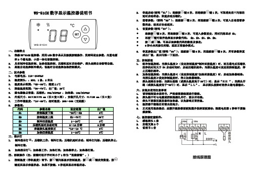
WS-51CH 数字显示温控器说明书一、功能特点1. 伟森WS-51CH 温控器,采用LED 数字显示及触摸按键操作,凭密码设定参数,内置电源和2个继电器,小型一体化智能控制。
2. 具有制冷恒温控制、加热恒温控制、压缩机延时启动保护、探头故障自诊断等功能。
3. 高温自动选择制冷模式,低温时自动选择加热控制模式。
二、技术参数1. 电源电压:110~240VAC2. 温度探头::NTC ,1条,2米长3. 温度显示范围:-45~90℃,精度±1℃4. 控温温度范围:-30~70℃,出厂值:20℃5. 继电器触点容量:压缩机:30A/240VAC ;加热器:10A/240VAC6. 外观尺寸:80×35×78 mm (长×宽×深),安装开孔尺寸:71×29 mm(长×宽)7. 工作环境温度:-10~60℃;相对湿度:20%~90%(无结露)8.1. 制冷指示灯:压缩机工作,制冷灯亮;压缩机延时启动,制冷灯闪烁;压缩机停止,制冷灯熄。
2.加热指示灯:加热器工作,加热灯亮;加热器停止,加热器灯熄。
四、面板操作(注:按键时松开手时间小于1秒为“连续按键”。
)1.控制温度(停机温度)调节:按键闪烁显示控制温度,按或键改变数值,按键返回显示库温状态,如果不按键,3秒返回显示库温状态。
2. 快速启动(密码“51”):连续按键5次、再连续按键1次,可取消处在闪烁的延时启动状态,快速启动压缩机。
3. 查看参数:(密码“52”):连续按键5次、再连续按键2次,可进入自动查看参数状态,结束后自动返回。
4. 设置参数(密码“53”): ● 连续按键5次、再连续按键3次,可进入参数设定,同时闪烁显示 E1;● 再按键可依序选择显示参数代码: E2、E3、E4、E5、E6;● 按或键,可显示该参数代码的数值及修改; ●6秒内未再按任何键,返回正常操作模式。
基于51单片机水温检测控制系统说明书

基于单片机的水温检测控制系统设计学生姓名王培同院系名称机电学院专业名称机械电子工程班级机电132学号201300384228指导教师完成时间目录1 引言 (3)2 设计要求 (3)2.1 基本要求 (3)2.2 扩展功能 (3)3 总体方案设计 (3)3.1 方案论证 (3)3.1.1 方案一 (3)3.1.2 方案二 (4)4 硬件设计 (4)4.1 单片机系统 (4)4.2 数字温度传感器模块 (5)4.2.1 DS18B20性能 (5)4.2.2 DS18B20外形及引脚说明 (5)4.2.3 DS18B20接线原理图 (6)4.2.4 DS18B20时序图 (6)4.2.5 数据处理 (7)4.3 显示电路 (8)4.4 声光报警电路 (9)4.5 键盘输入电路 (10)5 软件设计 (11)5.1 主程序模块 (11)5.2 读温度值模块 (11)5.3 中断模块 (11)5.4 温度设定、报警模块 (12)6 源程序 (12)7 总结 (12)参考文献: (13)1 引言随着人们生活水平的不断提高,单片机控制无疑是人们追求的目标之一,它所给人带来的方便是不可否定的,各种数字系统的应用也使人们的生活更加舒适。
数字化控制、智能控制为现代人的工作、生活、科研等方面带来方便。
其中数字温度计就是一个典型的例子。
数字温度计与传统的温度计相比,具有读数方便、测温范围广、测温精确、功能多样话等优点。
其主要用于对测温要求准确度比较高的场所,或科研实验室使用,该设计使用STC89C52RC单片机作控制器,数字温度传感器DS18B20测量温度,单片机接受传感器输出,经处理用LCD实现温度值显示。
2 设计要求2.1 基本要求实现实时温度显示,测温范围0~1200C,误差50C以内。
2.2 扩展功能温度报警,能任意设定温度范围实现温度的报警。
温度控制,利用继电器控制热得快,当设置好温度上下限后,当没有超过温度上限时,继电器吸合,热得快通电,加热水温。
制冷机操作及GW511A温控器使用说明
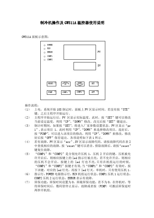
制冷机操作及GW511A 温控器使用说明GW511A 面板示意图: COMP2COMP1DOEN SETUP OFFPUMP RESET SVPVCOMP2COMP1ERRORRUNPOWER操作流程:(1) 上电,系统开始10S 倒记时,面板上PV 区显示时间。
若没有按“STE ”键,之后主程序开始运行。
(2) 主程序开始运行后,PV 区显示实际温度。
此时,按“SET ”键可以修改当前设定温度,利用“UP ”、“DOWN ”修改。
改完后按“SET ”键退出。
(3) 倒计时期间,如果按“SET ”,将进入厂家参数设置状态,PV 区显示“pr1”,表示项目1。
此时利用“UP ”、“DOWN ”来选择修改项目,选好后,按“PUMP ”,可以进入该项目的修改,利用“UP ”、“DOWN ”来修改,修改好后按“OFF ”保存退出。
各项说明如下表1所示。
(4) 若有故障,PV 区显示“err ”,SV 区显示故障代码。
请按故障代码在表2中查找相应的故障,按‘reset ”键可以消音,排除故障后,请按“reset ”键复位故障。
(5) “COMP1”和“COMP2”是分别允许压机1,压机2开启的键,压机被允许开启后,则相应按键上的led 指示灯被点亮;若不允许开启,则相应的压机不会开启,按键上的led 灯也不亮,只有在机组运行的时候,“COMP1”和“COMP2”按键才有效,当“COMP1”和“COMP2”有效时,按下该键,对应的led 灯亮,再按下led 灯灭。
单机时,只有使用压机1。
(6) 指示灯:POWER 电源指示灯;RUN 机组运行状态;COMP1压机1运行状态;COMP2压机2运行状态;ERROR 表示有故障。
(7) 屏保功能:屏保时间设置为0,屏敞屏保功能;若不为0,在停机时,等待屏保时间后,数码管停止显示,故障或者按〈PUMP 〉可激活屏保延时两秒开机组。
表1注:除参数4~9及20可根据客户需要设置外,其它参数请勿改动,以免造成温控器错误,动作不能正常工作。
基于51单片机的温度控制系统说明书

中北大学课程设计说明书学生姓名:学号:学院:机械与动力工程学院专业:机械电子工程题目:基于51单片机的温度控制系统设计职称: 讲师2015 年 1 月 19 日目录第1章绪论 (2)1.1 题目背景 (2)1.2 题目简介 (2)第2章系统总体设计及方案 (3)2.1单片机的介绍 (3)2.2系统功能的确定 (3)2.3温度传感器DS18B20的介绍 (3)2.3.1DS18B20的内部结构 (4)2.3.2 DS18B20的引脚介绍 (6)2.4人机交互与串口通信 (6)第3章硬件设计 (8)3.1系统结构框图 (8)3.2人机交互与串口通信单元设计 (9)3.2.1 键盘输入电路 (9)3.2.2 串口通信电路 (9)3.2.3 LED七段数码动态显示电路 (10)3.2.4 控制执行单元设计 (11)第4章软件设计 (12)4.1设计思路、程序代码 (12)结束语 (22)参考文献 (23)第1章绪论1.1 题目背景不论是对于工业生产还是对于人们的日常生活,温度的变化都会对其产生一定程度的影响。
所以,适时和恰当的温度控制对生产生活具有非常重要的作用。
在过去,对温度的控制总是采用常规的模拟调节器,然而,这种调节器存在的缺点是控制精度低,具有滞后、非线性等特点。
-本文将采用微电子技术来提高温度控制的精度,因为微电子技术的电路设计简单,控制效果好,具有很强的实用性。
众所周知,在现代工业以及家用电器测控领域中,单片机系统的开发和运用给其带来了全新的技术创新和变革。
而且,自动化和智能化程度的高低均依赖于是否使用单片机。
试想:将单片机的温度控制方法如果能够运用到温度控制系统中的话,那么,就可以在一定程度上缓减和克服温度控制系统中存在的滞后现象,同时在很大程度的上,单片机的使用可以提高温度的控制效果以及控制精度。
在工业自动化控制中,温度的控制一直都占有非常特殊的地位。
在本文中作者针对电烤箱的温控系统利用单片机进行设计,从而达到精确控制电烤箱温度目的。
51 单片机水温度控制系统

51 单片机水温度控制系统摘要:随着微机测量和控制技术的迅速发展与广泛应用,以单片机为核心的温度采集与控制系统的研发与应用在很大程度上提高了生产生活中对温度的控制水平。
本设计以保质、节能、安全和方便为基准设计了一套电热壶水温控制系统,能实现在40℃~90℃范围内设定控制温度,且95℃时高温报警,十进制数码管显示温度,在PC机上显示温度曲线等功能,并具有较快响应与较小的超调。
整个系统核心为SPCE061A,前向通道包括传感器及信号放大电路,按键输入电路;后向通道包括三部分:LED显示电路,上位机通信电路以及控制加热器的继电器驱动电路。
利用SPCE061A的8路10位精度的A/D转换器,完成对水温的实时采样与模数转换,通过数字滤波消除系统干扰,并对温度值进行PID运算处理,以调节加热功率大小。
同时在下位机上通过数码管显示当前温度,通过USB接口传送信息至上位机,可以直接在PC端观察温度的变化曲线,并根据需要进行相应的数据分析和处理,由此完成对水温的采样和控制。
通过验证取得了较满意的结果。
关键词:码分多址、walsh扩频、pn扩频、电路设计、程序设计、目录一.引言 (3)二.基于单片机水温控制系统设计过程 (4)2.1 总体方案论证 (4)2.2 各部分电路方案论证 (5)三.硬件电路设计 (6)3.1 温度检测和变送器 (7)3.2 接口电路 (8)3.3 温度控制电路 (10)3.4 键盘及数字显示结合 (10)3.5 温度设定和传送电路 (11)3.6 单片机控制部分 (12)3.7 键盘及数字显示部分 (12)结束语 (13)参考文献 (14)一.引言在现代化的工业生产中,电流、电压、温度、压力、流量、流速和开关量都是常用的主要被控参数。
例如:在冶金工业、化工生产、电力工程、造纸行业、机械制造和食品加工等诸多领域中,人们都需要对各类加热炉、热处理炉、反应炉和锅炉中的温度进行检测和控制。
采用MCS-51单片机来对温度进行控制,不仅具有控制方便、组态简单和灵活性大等优点,而且可以大幅度提高被控温度的技术指标,从而能够大大提高产品的质量和数量。
AI-516516P型人工智能温度控制器

3.3.1 单相移相触发输出 ................................................................................................................32 3.3.2 上电时免除报警功能.............................................................................................................32 3.3.3 通讯功能 ..............................................................................................................................33 3.3.4 温度变送器/程序给定发生器 ..............................................................................................33 4 程序控制(仅适用 AI-516P 型)..........................................................................................................34 4.1 功能及概念 ...................................................................................................................................34 4.2 程序编排 .......................................................................................................................................36 4.2.1 斜率模式 ..............................................................................................................................36 4.2.2 平台模式 ..............................................................................................................................37 4.2.3 时间设置 ..............................................................................................................................38 4.2.4 给定值设置...........................................................................................................................399 4.2.5 运行多条曲线时程序的编排方法...........................................................................................39
51温控系统说明书

基于单片机的简单温控系统机控学院 自动化12-2 潘星光 3120619213实现功能:利用单片机89C52和热电偶进行测量发热电阻的温度,利用 LCD1602进行显示的温度和人工可设置温度的上限与下限值,即有两个按键是 来控制上限值的大小,而另两个按键则是控制下限值的大小的。
发热电阻从系统 上电后就立即通电发热,设置好所需要温度范围,则测量温度显示的数值会随发 热电阻通电时间的增大而增大,当测量的温度超出所设定的上限值时, 就会驱动 蜂鸣器报警,发热电阻停止通电,同时也会驱动马达扇风来降温; 而当测量温度 低于所设定的下限值时,也会进行报警,但电机不会被启动和发热电阻也继续通 电发热。
当然当测量温度在上限值和下限值之间时, 是不会进行报警和驱动马达 的,但发热电阻仍处于通电状态中。
电路原理图:C1Z 3EX-X EHcrl dE总fill I w I ?LCD1KQDS1&E2:1KQ NO 昌口 口 A主程序:#in clude<reg52.h> dat=ds; _nop_();#i nclude<1602.h> TempDelay(12); }#i ncludevi ntri ns.h> return dat; dat>>=1;sbit ds = P2A2; } }sbit beep =卩2八3; uchar ds_read_byte() }sbit rd = P3A7; { 一一sbit k = P1A0;uchar i,j,value; void ds_cha nge()bit flag; for(i=0;i<8;i++) {uchar ds_rom[8]; { ds_reset();uchar H,L,Key_value; j=ds_read_bit(); ds_write_byte(0xcc); void TempDelay(uchar ds_write_byte(0x44) us) value=(j<<7)|(value>J{ >1); }while(us--); 〃6.51us } uchar get_temperature() } retur n value; {void ds_reset() } uint temp;{ _ void ds_write_byte(uchar uchar a,b,c;ds=1; dat) ds_reset();_nop_(); { ds_write_byte(0xcc);ds=0; uchar i,o nebit; ds_write_byte(0xbe);TempDelay(80);//52 for(i=0;i<8;i++) a=ds_read_byte();0us { b=ds_read_byte();ds=1; temp=b;TempDelay(5); on ebit=dat&0x01; temp<<=8;if(ds==0) if(on ebit) temp|=a;flag=1; //写1 c = temp*0.0625;else { return c;flag=0; ds=0; }TempDelay(20);ds=1; TempDelay(l); void key()} ds=1; {bit ds_read_bit() _nop_(); Key_value = P3; { 一一} Key_value = bit dat; else //写 0 Key_value & 0x0f;ds=0; { if ( Key_value !=_nop_(); ds=0; 0x0f )_nop_(); {ds=1; TempDelay(11); dela y(5);_nop_(); ds=1; if(Key_value != OxOf )_ {switch(Key_value) { _case OxOe: H++; break;case0x0d: H--; break;case0x0b: L++; break;case0x07: L--; break;}}}}void mai n(){uchar i;rd = 0;in it_1602();write_com( 0x80 + 0 + 3);write_data( 'H');write_com( 0x80 + 0 + 8);-write_data( 'L');lcd_dis( 0,5,ucharto s tr( H ));lcd_dis( 0,10,ucharto str( L ));if ( i>=H){beep = 0; k= 0;}else if(i<=L) {beep = 0; k =1;} else{beep =1; k =1;}key();}}lcd_distostr(1,1,0);H = 35;L = 25;k = 1;while(1){ds_cha nge();i =get_temperature();lcd_dis( 1,14,ucharto str( i ));头文件1602.h程序:#define uchar unsigned char#defi ne uint un sig ned int sbit wela = P2A7;sbit dula =卩2八6;sbit LCDEN =卩3八4; sbit rs = P3A5;sbit rw = P3A6;uchar datstr[] = "Temperature:";uchar str[4];//uchartostr 函数转换的字符串同时可以把16进制转成10进制void delay( uint z) 〃延时函数{uint x,y;for(x=z;x>0;x__)for(y=120;y>0;y--);}void write_com(uchar com) //写命令{P0=com;rs=0;LCDEN=0; delay(10);LCDEN=1; delay(10);LCDEN=0;}void write_data(uchar date) //写数据{P0=date;rs=1;LCDEN=0; delay(10);LCDEN=1;delay(10); LCDEN=0;}void in it_1602(){rw=0;dula=0;wela=0;write_com(0x38);//显示模式设置:16 x 2 显示,5X 7点阵,8位数据接口delay(20);write_com(0x0c);//显示模式设置delay(20);write_com(0x06);〃显示模式设置:光标右移,字符不移delay(20);write_com(0x01);//清屏幕指令,将以前的显示内容清除delay(20);}uchar *uchartostr(ucharnum) //将一个字节的数据转换为字符串或10进制{uchar x2,x1,x0,i;x2=num/100; x仁num%100/10;x0=num%100%10;i=0;if(x2!=0){str[i]=x2+48; i++;} if(x1!=0){str[i]=x1+48; i++;} str[i]=x0+48;i++; str[i]='\0'; returnstr;}void lcd_dis(ucharX,uchar Y,uchar *dis) // 显示数据数组{uchar pos; switch(X){case 0:X=0x00;break;case 1:X=0x40;break;break;default:break;}pos =0x80+X+Y;write_com(pos);//显示地址while(*dis!='\0'){ write_data(*dis++);}}void lcd_distostr(ucharX,uchar Y,uchar dis)// 显示字符串数组{uchar pos,i;i=dis; //设定从数组中的第几个字符串开始显示switch(X){case O:X=OxOO; break;case 1:X=0x40; break; break; defaultbreak;}pos =0x80+X+Y; write_com(pos);//显示地址while(datstr[i] !='\0') {write_data(datstr[i]);i++;主要问题:在只使用一个电源供电时,马达启动的瞬间,单片机会掉电重启以致使系统不能稳定工作下去。
基于51单片机的空调温度控制设计说明

基于MCS-51单片机的空调智能温控器的设计与开发摘要本控制电路是以8051单片机为控制核心。
整个系统硬件部分包括温度采样电路,自激式A/D转换器,按键电路,驱动电路,时序电路,和8段译码器,LED数码显示器。
在配合用汇编语言编制的程序使软件实现,实现空调温度智能转换的基本功能。
本控制电路成本低廉,功能实用,操作简便,有一定的实用价值。
本文从3个方面展开论述,首先是硬件电路的描述;接着软件部分的设计;最后实现功能。
关键词8051单片机温度控制 LED数码显示一系统总体设计方案1.1 课题背景电子技术的发展,特别是随着大规模集成电路的产生,给人们的生活带来了根本性的变化,如果说微型计算机的出现使现代的科学研究得到了质的飞跃,那么单片机技术的出现则是给现代工业控制测控领域带来了一次新的革命。
目前,单片机在工业控制系统诸多领域得到了极为广泛的应用。
特别是其中的C51系列的单片机的出现,具有更好的稳定性,更快和更准确的运算精度,推动了工业生产,影响着人们的工作和学习。
在现代社会中,温度控制不仅应用在工厂生产方面,其作用也体现到了各个方面,随着人们生活质量的提高,酒店厂房与家庭生活中都会见到温度控制的影子,温度控制将更好的服务于社会.而今,空调等家用电器随着生产技术的发展和生活水平的提高越来越普与,一个简单,稳定的温度控制系统能更好的适应市场。
而本次设计就是要通过以MCS-51系列单片机为控制核心,实现空调机温度控制器的设计。
方案一通过温度传感器对空气进行温度采集,将采集到的温度信号传输给单片机,再由. . . .单片机控制显示器,并比较采集温度与设定温度是否一致,然后驱动空调机的加热或降温循环对空气进行处理,从而模拟实现空调温度控制单元的工作情况。
空调温控器主要单片机,时序电路,温度采样电路,A/D转换电路,温度显示电路,温度输入电路,驱动电路等组成。
系统原理图见图1所示:图1 空调机温度控制系统框图方案二DS18B20单线连接方案,方案二采用单线连接,就是四块DS18B20连到单片机的一个IO口上,这种方案只用到单片机的一个IO口,大大的节约了单片机的IO口资源。
杭州市域温湿度控制器SNT-511设定说明书
杭州市域温湿度控制器SNT-511设定说明书
温湿度控制器主要功能说明:
1、正常工作时,流入保护器的电流不超过0.1mA,不影响CT正常工作。
2、当A(或B、C),N两端电压超过150V时,BT-CTB短接A(或
B、C)与N。
3、继电器的接点容量大于15A,所以故障时,能使CT二次侧可靠短路。
4、继电器接点具有保持功能,按压“复位”按钮,才能解除保护功能。
5、若是在停电状态下解除了故障,掉电后装置自动复位。
6、装置提供一对常开接点和一对常闭接点,可接各种声光报警器或提供给综合保护装置使信息远传。
当保护动作时,常开闭合,常闭打开,接线方式下面查看安装使用介绍。
7、注意加湿水泵因时间过长不使用而出现水沉淀物造成止转,在拨动口拨动风叶使之转动。
- 1、下载文档前请自行甄别文档内容的完整性,平台不提供额外的编辑、内容补充、找答案等附加服务。
- 2、"仅部分预览"的文档,不可在线预览部分如存在完整性等问题,可反馈申请退款(可完整预览的文档不适用该条件!)。
- 3、如文档侵犯您的权益,请联系客服反馈,我们会尽快为您处理(人工客服工作时间:9:00-18:30)。
基于单片机的简单温控系统机控学院自动化12-2 潘星光3120619213实现功能:利用单片机89C52和热电偶进行测量发热电阻的温度,利用LCD1602进行显示的温度和人工可设置温度的上限与下限值,即有两个按键是来控制上限值的大小,而另两个按键则是控制下限值的大小的。
发热电阻从系统上电后就立即通电发热,设置好所需要温度范围,则测量温度显示的数值会随发热电阻通电时间的增大而增大,当测量的温度超出所设定的上限值时,就会驱动蜂鸣器报警,发热电阻停止通电,同时也会驱动马达扇风来降温;而当测量温度低于所设定的下限值时,也会进行报警,但电机不会被启动和发热电阻也继续通电发热。
当然当测量温度在上限值和下限值之间时,是不会进行报警和驱动马达的,但发热电阻仍处于通电状态中。
电路原理图:主程序:#include<reg52.h>#include<1602.h>#include<intrins.h>sbit ds = P2^2;sbit beep = P2^3;sbit rd = P3^7;sbit k = P1^0;bit flag;uchar ds_rom[8];uchar H,L,Key_value; void TempDelay(uchar us){while(us--); //6.51us }void ds_reset(){ds=1;_nop_();ds=0;TempDelay(80);//52 0usds=1;TempDelay(5);if(ds==0)flag=1;elseflag=0;TempDelay(20);ds=1;}bit ds_read_bit(){bit dat;ds=0;_nop_();_nop_();ds=1;_nop_();dat=ds;TempDelay(12);return dat;}uchar ds_read_byte(){uchar i,j,value;for(i=0;i<8;i++){j=ds_read_bit();value=(j<<7)|(value>>1);}return value;}void ds_write_byte(uchardat){uchar i,onebit;for(i=0;i<8;i++){onebit=dat&0x01;if(onebit)//写1{ds=0;TempDelay(1);ds=1;_nop_();}else //写0{ds=0;TempDelay(11);ds=1;_nop_();}dat>>=1;}}void ds_change(){ds_reset();ds_write_byte(0xcc);ds_write_byte(0x44);}uchar get_temperature(){uint temp;uchar a,b,c;ds_reset();ds_write_byte(0xcc);ds_write_byte(0xbe);a=ds_read_byte();b=ds_read_byte();temp=b;temp<<=8;temp|=a;c = temp*0.0625;return c;}void key(){Key_value = P3;Key_value =Key_value & 0x0f;if ( Key_value !=0x0f ){delay(5);if( Key_value != 0x0f ){switch(Key_value){case0x0e: H++; break;case0x0d: H--; break;case0x0b: L++; break;case0x07: L--; break;}}}}void main(){uchar i;rd = 0;init_1602();write_com( 0x80 + 0 + 3);write_data( 'H' );write_com( 0x80 + 0 + 8);write_data( 'L' );lcd_distostr(1,1,0);H = 35;L = 25;k = 1;while(1){ds_change();i = get_temperature();lcd_dis( 1,14,ucharto str( i ) );lcd_dis( 0,5,ucharto s tr( H ) );lcd_dis( 0,10,ucharto str( L ) );if ( i>=H){beep = 0;k = 0;}else if(i<=L){beep = 0;k = 1;}else{beep = 1;k = 1;}key();}}头文件1602.h程序:#define uchar unsigned char#define uint unsigned int sbit wela = P2^7;sbit dula = P2^6;sbit LCDEN = P3^4; sbit rs = P3^5;sbit rw = P3^6;uchar datstr[] = "Temperature:";uchar str[4];//uchartostr 函数转换的字符串同时可以把16进制转成10进制void delay(uint z) //延时函数{uint x,y;for(x=z;x>0;x--)for(y=120;y>0;y--); }void write_com(uchar com) //写命令{P0=com;rs=0;LCDEN=0;delay(10);LCDEN=1;delay(10);LCDEN=0;}void write_data(uchar date) //写数据{P0=date;rs=1;LCDEN=0;delay(10);LCDEN=1;delay(10);LCDEN=0;}void init_1602(){rw=0;dula=0;wela=0;write_com(0x38);//显示模式设置:16×2显示,5×7点阵,8位数据接口delay(20);write_com(0x0c);//显示模式设置delay(20);write_com(0x06);//显示模式设置:光标右移,字符不移delay(20);write_com(0x01);//清屏幕指令,将以前的显示内容清除delay(20);}uchar *uchartostr(ucharnum) //将一个字节的数据转换为字符串或10进制{uchar x2,x1,x0,i;x2=num/100;x1=num%100/10;x0=num%100%10;i=0;if(x2!=0){str[i]=x2+48;i++;}if(x1!=0){str[i]=x1+48;i++;}str[i]=x0+48;i++;str[i]='\0';return str;}void lcd_dis(ucharX,uchar Y,uchar *dis) //显示数据数组{uchar pos;switch(X){case 0:X=0x00;break;case 1:X=0x40;break;break;default:break;}pos =0x80+X+Y;write_com(pos);//显示地址while(*dis!='\0'){write_data(*dis++);}}void lcd_distostr(ucharX,uchar Y,uchar dis)//显示字符串数组{uchar pos,i;i=dis; //设定从数组中的第几个字符串开始显示switch(X){case 0:X=0x00;break;case 1:X=0x40;break;break;default:break;}pos =0x80+X+Y;write_com(pos);//显示地址while(datstr[i] !='\0' ){write_data(datstr[i]);i++;}}主要问题:在只使用一个电源供电时,马达启动的瞬间,单片机会掉电重启以致使系统不能稳定工作下去。
可能原因:马达启动瞬间电流过大,以致此时单片机失电。
解决方法:采用双电源供电。
结果:在做好实物进行检验,系统通电后,设定好一个温度范围,经过一段时间后系统能按原设计思想进行温度报警和电机转动降温;但其中利用马达转动扇风降温,不能降至温度下限值以下,并且发热电阻在进行发热时,温度上升的速率也会较慢。
但在利用人为的方法后进行实验,发现系统可基本上按原设计思路运行。
总结:虽此次的实物并非能利用PCB板做出,而是利用万用板和单片机最小系统进行连接完成的,但所设计思路也能基本上利用硬件表达出来。
而最终的控制温度精度也不是很高,只有1℃左右,也算实现一个温度的粗略控制,这其中仍有许多地方有待改进。
而我也通过此次的实践,更加的加深单片机知识,也深知自身还有许多知识要去掌握。
说明书。