路灯箱变208终端说明书v1.2
DSA208+组态型监控装置技术说明书V2.01
智能终端说明书
台区智能配变终端TTU说明书XXXXXXXX公司目录1.概述_______________________________________________________________________ 21.1应用范围_______________________________________________________________ 21.2 产品特点 ______________________________________________________________ 32.终端结构___________________________________________________________________ 32.1终端外观_______________________________________________________________ 32.2结构设计_______________________________________________________________ 43. 主要技术指标______________________________________________________________ 43.1使用环境_______________________________________________________________ 43.2电源工作指标___________________________________________________________ 43.3模拟量_________________________________________________________________ 53.4功率消耗_______________________________________________________________ 54.终端功能___________________________________________________________________ 54.1 终端基本架构 __________________________________________________________ 54.2配变监测_______________________________________________________________ 54.3状态量采集_____________________________________________________________ 64.4通讯通道_______________________________________________________________ 64.5台区设备监测___________________________________________________________ 64.6数据处理及传送_________________________________________________________ 74.7数据统计_______________________________________________________________ 74.8就地及外接设备异常指示_________________________________________________ 74.9后备电源_______________________________________________________________ 84.10自恢复________________________________________________________________ 84.11无线管理______________________________________________________________ 84.12安全防护______________________________________________________________ 85.终端端子图及指示灯定义_____________________________________________________ 95.1 终端侧面端子定义图____________________________________________________ 95.2 终端指示灯定义_______________________________________________________ 105.3重载连接器接口定义___________________________________________________ 106.调试口简要说明____________________________________________________________ 117.终端故障及解决方法________________________________________________________ 128.装箱清单__________________________________________________________________ 121.概述1.1应用范围台区智能配变终端安装于柱上变压器台区,具备对配电变压器0.4kV低压设备实现电能分配、电能计量、无功补偿以及供用电信息的自动测量、采集、保护、监控及安全防护等功能。
箱变初步设计说明书

箱变初步设计说明书目录1.总述 (1)1.1设计依据 (1)1.2工程规模 (1)1.3设计范围 (1)1.4设计所依据的主要规程、规范: (1)1.5电缆选择 (2)1.6开关柜选择 (2)2.线路路径 (3)3.箱变部分 (4)3.1主接线 (4)3.2主要电气设备选择 (4)3.3无功补偿 (5)3.4 保护 (5)3.5仪表配置 (5)3.6 箱变接地 (6)4.气象条件 (6)5.工程地质 (7)5.1土壤计算参数 (7)5.2路面结构 (7)6.电力管道设计 (7)6.1管道埋深 (7)6.2管道材料 (7)6.3管道铺设 (8)6.4管道人孔井 (9)6.5顶(拉)管施工 (10)7.土建部分 (12)8.施工说明 (13)1.总述1.1设计依据1.1.1 项目设计合同1.1.2甲方设计委托及甲方提供的相关资料1.1.3现场踏勘、勘察资料1.2工程规模1)本工程新建路灯箱变10座,其中1进3出环网型100kVA箱变1座,1进5出环网型80kVA箱变1座,1进2出环网型160kVA箱变1座,1进2出环网型100kVA箱变2座,1进2出环网型80kVA箱变4座,1进2出环网型50kVA箱变1座。
2)本工程新建电缆线路路径长度共计5296米,其中利用本工程新建管线敷设3458米,直埋敷设1838米。
电缆采用ZC-YJLV22-8.7/15-3×120铝电缆和ZC-YJLV22-8.7/15-3×70铝电缆。
3)本工程新建4孔顶管路径长度400米,新建4孔排管路径长度190米,新建2孔顶管路径长度868米,新建2孔排管路径长度1210米。
新建直通型电缆井19座,T型电缆井3座,电缆顶管保护管采用HDPE-150/10,排管保护管采用MPP-150/10。
4)本工程融科开闭站新增10kV出线柜1面,新建线路安装用户分界开关4台、预付控开关5台。
1.3设计范围1.3.1 本工程路灯箱变及箱变10kV电源线的本体设计。
HNR-2082 微机PT监测保护装置 技术使用说明书(2)

HNR-2082微机PT监测保护装置技术使用说明书(V2.0)2012年08月08日杭州国电南瑞智能设备有限公司应用范围适用于我国35kV及以下电压等级的工矿企业、民用建筑配电的小电流接地系统。
可完全替代传统的继电器保护,为高低压开关柜、箱式变电站、环网柜、户外开关等一次设备完成PT监控功能,可用于高低压开关柜制造厂、变电站、开闭所、石油、石化、化工、煤炭、建筑等各种行业的高低压配电系统中。
装置硬件电路板分层方式,强弱电分离,很强的抗电磁干扰能力;强型金属机箱按抗强振动、强干扰设计,可分散安装于开关柜上运行,也可以集中组屏安装。
采用32位微控制器,内含大容量的RAM和Flash Memory,做到总线不出芯片,增强抗干扰能力;数据处理、逻辑运算和信息存储能力强,运行速度快,可靠性高。
12位高精度A/D,测量精度高。
采用中文图形液晶显示,菜单式操作。
装置生产采用全自动化贴片、波峰焊生产线,在工艺上充分保证制造质量。
具有RS-485通讯接口和Modbus规约。
主要特点模块化编程;实时性好,可靠性高。
保护与控制一体化。
直接显示二次侧相位,用户可直观地了解现场接线情况。
开关变位状态实时刷新,可直接从面板显示屏观察。
可保存不少于255个最近发生的事件报告及运行报告。
软件上采用彻底的模块化、平台化设计,显著提高了产品的可信赖性和可维护性。
支持Modbus-RTU规约,消除了装置通信接入的软件瓶颈,可以很方便地和国内外众多厂家的硬件设备或软件系列进行联接。
采用微型精密电流、电压互感器,体积小,重量轻,负载小。
免调节、易维护的概念设计,整机无可调节元件,选用高精度、高稳定的工业级器件,保证正常运行的高精度,避免因环境改变或长期运行而造成的采样误差增大。
具有完善的自检功能,能够检测装置的异常状态并显示出来。
我公司保留对本说明书进行修改的权利产品与说明书不符时,请参照实际产品说明2012.8第二版印刷目录1.装置简介 (1)1.1功能配置 (1)1.2主要特点 (1)2.技术指标 (2)2.1额定数据 (2)2.2装置功耗 (2)2.3环境条件 (2)2.4抗干扰性能 (2)2.5绝缘性能 (3)2.6机械性能 (3)2.7保护定值整定范围及误差 (3)2.8测量精度 (3)2.9装置自身时钟精度 (3)2.10触点性能 (3)3.主要功能 (4)3.1低电压保护 (4)3.2过电压保护 (4)3.3零序过压保护 (4)3.4PT断线保护 (4)3.5装置故障告警 (4)3.6遥测、遥信、遥控功能 (5)3.7通信 (5)4.保护信息说明 (5)4.1定值整定 (5)4.2保护投退 (5)5.装置人机接口及其操作 (6)5.1装置正面布置图 (6)5.2机箱结构 (7)5.3主菜单目录 (7)5.4主显示界面 (8)5.5菜单操作 (9)5.5.1主菜单 (9)5.5.2密码操作 (9)5.5.3记录子菜单 (9)6.用户调试方法 (11)6.1通电前检查 (11)6.2通电检查 (11)6.3开关量输入检查 (11)6.4继电器开出回路检查 (11)6.5灯测试 (11)6.6模拟量输入检查 (11)6.7整组试验 (12)6.8异常处理 (12)7.接线原理图 (13)8.投运说明及注意事项 (13)9.贮存及保修 (13)9.1贮存条件 (13)9.2保修时间 (14)10.供应成套性 (14)11.订货须知 (14)1.装置简介HNR-2082微机PT监测保护装置(以下简称装置)是集保护、监视、控制、人机接口和通讯等多种功能于一体,以电流、电压保护为基本配置的数字式保护单元,适用于我国35kV及以下电压等级的工矿企业、民用建筑配电的小电流接地系统,作为PT柜的保护、监控功能。
PT208使用手册

6
数字化·智能压力/差压变送器
测量开口容器液位时,变送器装在靠近容器的底部,以便测量其上方液面高度所对应的压力。容器液 位的压力,作用于变送器的高压侧,而低压侧通大气。如果被测液位变化范围的最低液位,在变送器安装 处的上方,则变送器必须进行正迁移。 密闭容器的液位测量 在密闭容器中,液体上面容器的压力 P0 影响容器底部被测的压力。因此,容器底部的压力等于液面 高度乘以液体的比重再加上密闭容器的压力 P0。为了测得真正的液位,应从测得的容器底部压力中减去容 器的压力 P0。为此,在容器的顶部开一个取压口,并将它接到变送器的低压侧。这样容器中的压力就同时 作用于变送器的高低压侧。结果所得到的差压就正比于液面高度和液体的比重乘积了。 导压连接方式 1)干导压连接 如果液体上面的气体不冷凝,变送器低压侧的连接管就保持干的。这种情况称为干导压连接。决定变 送器测量范围的方法与开口容器液位的方法相同。 2)湿导压连接 如果液体上面的气体出现冷凝, 变送器低压侧的导压管里就会渐渐地积存液体, 从而引起测量的误差。 为了消除这种误差,预先用某种液体灌充在变送器的低压侧导压管中,这种情况称湿导压连接。 上述情况,使变送器的低压侧存在一个压头,所以必须进行负迁移。 测量误差 导压管使变送器和流程工艺管道连在一起,并把流程工艺道上取压口处的压力传输到变送器。在压力 传输过程中,可能引起误差的原因如下: 1)泄漏; 2)摩擦损失(特别使用洁净剂时) ; 3)液体管路中有气体(引起压头误差) ; 4)气体管路中存积液体(引起压头误差) ; 5)两边导压管之间因温差引起的密度不同(引起压头误差) ; 减少误差的方法 1)导压管应尽可能短些; 2)当测量液体或蒸汽时,导压管应向上连到流程工艺管道,其斜度应小于 1/12 ; 3)对于汽体测量时,导压管应向下连接到流程工艺管道,其斜度应不小于 1/12 ; 4)液体导压管的布设要避免中间出现高点,气体导压管的布设要避免中间出现低点; 5)两导压管应保持相同的温度; 6)为避免摩擦影响,导压管的口径应足够大; 7)充满液体导压管中应无气体存在; 8)当使用隔离液时,两边导压管的液体要相同;
AB-208灯光智能控制使用说明

智能报警联动控制器安装指南
智能报警联动控制器只需一个常闭或常开输入:如红外探头,对射,紧急按钮等常闭端,即可联动另一端的强电开关(常开同样效果)。
1. 性能特点:
输出即时跟随输入功能(输入关输出也关;输入开输出也开)
输出延时跟随输入功能时间可由用户通过拨码设定(精确到5秒),最长10分钟
3.指示灯说明
●电源指示灯: 通电后就会亮
●状态指示灯: 即时联动(未拨码)情况下,快速闪烁;延时联动(拨码)情况下,1秒钟闪烁1次
●高压操作指示灯:高压继电器操作时变换指示
●低压操作指示灯:低压继电器操作时变换指示
4.使用说明
输出即时跟随输入功能不拨码,即2--8位拨码开关都是OFF
输出延时跟随输入功能拨码(见拨码开关对应时间表),最短延时为5秒,最长10分钟
具体的时间=下表的秒数* 基数(基数为5秒)
例:用户希望延时为30秒,应当拔开关数设成6,则实际继电器的闭合延迟时间将为:6 *5=30秒。
其它以此类推。
;用户想采用其他基数请在定购产品时说明。
拨码开关第1位用来设置输入端接法,1为OFF输入端接常闭,1为ON输入端接常开。
专变采集终端使用说明书

集系统通信协议》等标准对终端的要求。 在安装使用本终端前,请先仔细阅读本手册。
1 主要特点
1.1 高性能 32 位 CPU,大容量存储,高精度时钟, 高点阵大屏幕液晶的硬件平台,满足数据采集、 存储,高速运算,通讯,控制等要求。
概述 ..............................................................................2 主要特点 ......................................................................2 技术指标 ......................................................................3 安装与接线 ..................................................................5 安装 ..............................................................................5 端子接线说明 ..............................................................8 本地 RS232 端口 ......................................................10 红外接口 ....................................................................10 终端面板说明 ............................................................11 面板说明 ....................................................................11 指示灯说明 ................................................................12 液晶显示与键盘操作 ................................................13 运输和贮存 ................................................................15 售后服务 ....................................................................16
美国Eaton公司的单相208 230V监控PDU产品说明说明书
3.7kW Single-Phase 208/230V Monitored PDU -LX Platform, 8 C13 Outlets, C20 Input with L6-20P Adapter, 2.4m Cord, 1U Rack-MountMODEL NUMBER:PDUMNH20HVFeatures16/20A 230/208V Monitored Power Distribution Unit / PDU (agency derated to 16A continuous)qC20 inlet; 8ft / 2.4m C20 cable and NEMA L6-20P plug adapter includedq1U horizontal rackmount installationq8 C13 outletsqLighted display reports output power consumption in ampsqBuilt-in network interface reports voltage, frequency and PDU loading via network or secure web browser interface with options for user specified alarm and notification thresholdsqPre-installed WEBCARDLX with the latest version of PowerAlert Device Manager firmware (PADM20) provides enhanced remote management capabilitiesqPADM20 and PowerAlert Element Manager (PAEM) form a powerful tool for expanding maintenance functions in large installations, including firmware update checks and backup and restoration of device configurationsqOptional EnviroSense2 modules (sold separately) provide a variety of environmental monitoring capabilitiesq10/100 Mbps auto-sensing allows optimal communication with 10/100 Base-T networksqReal-time clock backup maintains the time of day and date even if the PDU is unpoweredqTiered access privileges allow an administrator and a guest to login via web browser for monitoringqAlert notifications via email or SNMP traps offer immediate event notificationqFirmware upgrade ability supports future product enhancements.qMounting flanges support installation in 2 and 4 post racks, with additional support for wall-mount and under-counter installation formatsqMounting ears are reversible for front or rear facing rackmount installationqIncluded cord retention brackets keep vital network equipment plugged in and continuously powered qTAA Compliant for GSA Schedule purchasesq HighlightsMonitored 16A 208/230V PDU,1U horizontal rackmountqReports voltage, frequency &load level via ethernet interface qVisual current meter, Reversible housingqC20 inlet; 8ft / 2.4m C20 cablewith L6-20P plug adapterq8 C13 outlets with included plug-lock retention sleevesqPre-installed WEBCARDLX with latest version of PADM20 forenhanced remote management qTAA Compliant for GSASchedule purchasesqPackage IncludesRackmount PDUqRack mounting bracketsqPlug retention insertsq2.6m C19-to-C20 power cordqC19-to-L6-20P plug adapterqMounting hardwareqOwner's manualqSpecifications© 2023 Eaton. All Rights Reserved. Eaton is a registered trademark. All other trademarks are the property of their respective owners.。
力创科技 LCDG-DTSD208 三相电子式电能表 用户使用手册说明书
LCDG-DTSD208三相电子式电能表用户使用手册山东力创科技有限公司版权所有,未经本公司书面许可,此手册中任何段落,章节内容均不得被摘抄、拷贝或以任何形式复制、传播,否则一切后果由违者自负。
本公司保留一切法律权利。
本公司保留对本手册所描述之产品规格进行修改的权利,恕不另行通知,订货前,请向厂商或代理商获取本产品的最新规格。
按照说明书指示的使用方法正确使用可以避免产品出现不必要的故障或损坏,并可保证使用者的安全。
1、使用过程中对操作者造成危险的安全注意事项。
(1)为确保正确、安全使用本产品,需专业电工安装或拆卸;(2)安装或拆卸操作时,必须断开主电源;2、个人维护、调整或更换易损件时,可能对操作者造成人身伤害。
(1)请勿擅自拆开产品,更不可带电拆机。
请用户严格按照本说明书说明安装和使用本产品,以获得最佳使用效果。
第一章简介 (5)1.1模块技术参数及指标 (5)1.2产品功能简介 (6)第二章安装与接线 (7)2.1外形尺寸 (7)2.2安装方式 (7)2.3面板说明 (7)2.4端子定义及接线方式 (8)第三章基本功能及操作与使用 (10)3.1概述 (10)3.1.1界面说明 (10)3.1.2按键说明 (11)3.1.3LED功能说明 (11)3.2按键操作说明 (12)3.3产品功能详解 (16)第四章寄存器列表 (18)第五章包装及注意事项 (22)第一章简介LCDG-DTSD208三相电子式电能表是山东力创科有限公司集多年的电能计量产品设计经验,所推出的新一代导轨式安装的微型电能表。
该电能表采用LCD显示,可显示:分相电压、分相电流、总有功功率、分相有功功率、总无功功率、分相无功功率、组合有功电能、正向有功电能、日期、时间、地址、表号、波特率、校验位、电流变比。
并具有电能脉冲输出功能;可用RS485通讯接口与上位机实现数据交换,极大的方便用电自动化管理。
该电能表具有体积小、安装方便等优点,且具有极高的精度和良好的EMC性能。
GCAN-208系列CAN光纤转换器 用户手册

GCAN-208-1/-2CAN光纤中继器用户手册文档版本:V3.50(2018/07/18)修订历史版本日期原因V1.002014/12/10创建文档V2.012015/03/20修正设备工作参数V3.012015/08/04添加部分参数V3.502018/07/18调整文档结构,新增自动识别波特率功能目录目录 (3)1.功能简介 (4)1.1功能概述 (4)1.2性能特点 (4)1.3选型指南 (5)1.4典型应用 (5)2.设备安装 (6)2.1设备尺寸 (6)2.2设备固定 (6)2.3接口定义及功能 (7)3.设备使用 (11)3.1CAN总线配置 (11)3.2与光纤连接 (15)3.3与CAN-bus连接 (15)3.4CAN总线终端电阻 (16)3.5系统状态指示灯 (16)4.技术规格 (18)5.常见问题 (19)附录CAN2.0B协议帧格式 (20)1.功能简介1.1功能概述沈阳广成科技有限公司GCAN-208系列模块是集成1路(或2路)标准光纤接口(单模、多模,SC、ST可选)、2路(或1路)标准CAN总线接口的工业级CAN总线转光纤转换器。
GCAN-208系列模块可以将CAN总线数据转换成光信号通过光纤传输。
通过成对使用GCAN-208系列模块,用户可以轻松的延长CAN总线通信距离、有效的消除长距离通信干扰,可以防止总线受到电磁干扰、地环干扰、雷击等对总线和设备造成的损坏。
GCAN-208系列模块可将CAN总线数据透明、无损的转换成光信号,再将光信号透明、无损的解析成CAN总线数据。
广成科技使用独有的总线信号转换技术,可将CAN数据与光信号之间的转换时间做到微秒级,这样就保证了通信的实时性,所以GCAN-208可支持任何CAN总线通信协议如:CANopen、SAE J1939、DeviceNet、NMEA2000等等。
GCAN-208-1模块独特的双通道设备可以同时延长两条CAN总线的通信距离,GCAN-208-2模块具有两套光纤接口,可用于级联。
箱式变电站安装使用说明书
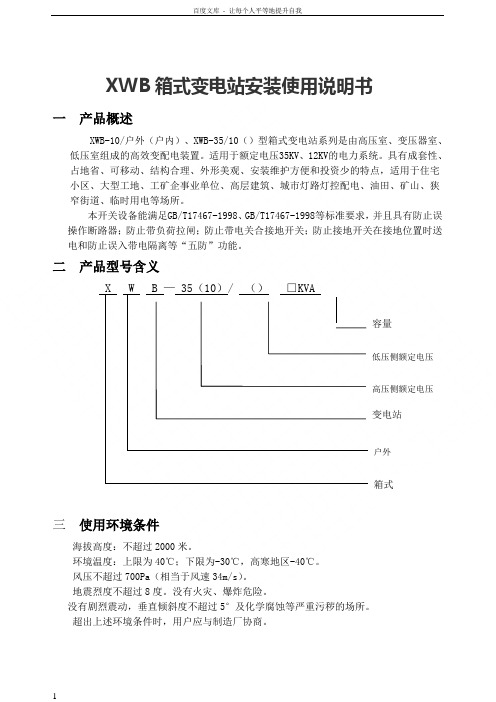
XWB箱式变电站安装使用说明书一产品概述XWB-10/户外(户内)、XWB-35/10()型箱式变电站系列是由高压室、变压器室、低压室组成的高效变配电装置。
适用于额定电压35KV、12KV的电力系统。
具有成套性、占地省、可移动、结构合理、外形美观、安装维护方便和投资少的特点,适用于住宅小区、大型工地、工矿企事业单位、高层建筑、城市灯路灯控配电、油田、矿山、狭窄街道、临时用电等场所。
本开关设备能满足GB/T17467-1998、GB/T17467-1998等标准要求,并且具有防止误操作断路器;防止带负荷拉闸;防止带电关合接地开关;防止接地开关在接地位置时送电和防止误入带电隔离等“五防”功能。
二产品型号含义X W B — 35(10)/ ()□KVA容量低压侧额定电压高压侧额定电压变电站户外箱式三使用环境条件海拔高度:不超过2000米。
环境温度:上限为40℃;下限为-30℃,高寒地区-40℃。
风压不超过700Pa(相当于风速34m/s)。
地震烈度不超过8度。
没有火灾、爆炸危险。
没有剧烈震动,垂直倾斜度不超过5°及化学腐蚀等严重污秽的场所。
超出上述环境条件时,用户应与制造厂协商。
四结构概述本系列产品系框架结,用型钢经特殊防腐处理后焊接而成。
外壳可采用防锈铝合金板、彩色夹心钢板、非金属。
箱顶为双层结构具有隔热、排气降温的作用。
所有操作均在柜门关闭状态下进行。
具备完善有效的“五防”功能,防止误操作。
进出线方式:高压电缆进,低压电缆出;高压电缆进,低压架空出;高压架空进,低压电缆出;高压架空进,低压架空出。
高压侧一次供电系统可布置成环网供电、终端供电、双电源供电等多种供电方式,还可装设高压计量元件,满足高压计量的要求。
变压器室可选择 S9、S11以及其他低损耗油浸式变压器和干式变压器;变压器(如变压器容量大于1600KVA,变压器敞开布置)设有自起动强迫风冷系统及照明系统。
采用自然通风和强迫通风两种方式,通风冷却性能良好。
icom IC-208H中文说明书
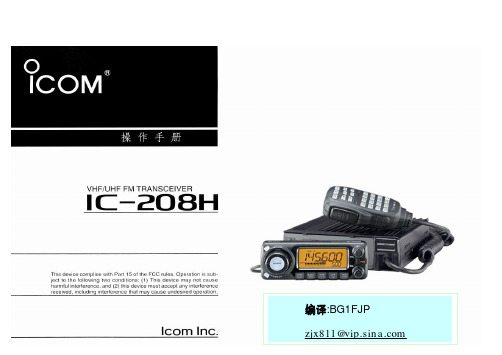
译者自述因为购买了IC-208H,所有有时间细看了一遍英文说明书。
这对于了解这部电台的特性和使用方法,充分开发它的用途是很有必要的。
因此花了一些时间把它翻译成中文,并送给所有拥有这款电台或对业余电台感兴趣的朋友们。
为了便于大家阅读,我完全按照原文的格式编译这本说明书,包括页码、插图都与原文相同。
同时,也请各位朋友对照原文阅读,帮助找出译文中的错误。
在译文中,我用“按”,“按一下”“按动”等词表示快速触按相应的按键,用“按住”表示要按一秒钟。
请大家在操作的时候注意这个区别。
BG1DOT对我翻译这本说明书给予了大力支持,并提供服务器空间存放这本手册供大家下载。
在此表示感谢!希望有机会与各位朋友通联,交流参加业余电台活动的经验和感受!VERY 73! BG1FJP配套附件目录1..面板描述……………………………1-10前面板—控制器 (1)功能显示 (3)后面板 (5)手咪(HM-133) (7)手咪键盘 (8)备选手咪 (10)2. 设置一个频率……….……………11-14准备 (11)使用调谐旋钮 (12)使用【▲】【▼】键 (12)使用键盘 (12)直流电缆线(3米)..........................1 调谐步长设置.. (13)车载安装支架...............................1 锁止功能.. (14)手咪(HM-133)................................1 3. 基本操作................................15-18 保险管(20A)..................................1 接收. (15)安装螺丝,螺母,垫圈......................1套监听功能.. (15)手咪挂钩.....................................1 静躁衰减器 (16)面板分离电缆(3.5米)....................1 发射. (17)选择输出功率 (17)单触PTT功能...............................18 扫描恢复条件.. (45)静音功能.....................................18 8.优先监听.................................46-47 4.中继设置...............................19-25 优先监听类型.. (46)概述...........................................19 优先监听操作.. (47)配置中继....................................20 9.DTMF存储编码..........................48-51 亚音...........................................22 编制一个DTMF码. (48)差频...........................................24 传送一个DTMF码. (50)自动中继(仅限美国版本)................25 DTMF速率.. (51)5.存储设置...............................26-37 10.寻呼及音频静躁......................52-55 概述...........................................26 寻呼操作.. (52)选择存储信道...............................26 音频/数字音频静躁操作. (54)编制存储信道...............................27 静躁频率扫描.. (55)复制存储内容..............................29 11.其他功能...............................56-74 编制信道名称...............................31 设置模式.. (56)清除存储.....................................34 初始设置模式.. (61)选择存储编组...............................35 AM/FM窄带模式 (65)设置存储编组..............................36 天气预报操作(仅限美国版本).. (66)传输编组内容..............................37 手咪键.. (67)6.呼叫信道设置........................38-39 局部重置.. (68)选择呼叫信道..............................38 全部重置.. (68)传输呼叫信道..............................38 克隆数据.. (69)编制呼叫信道..............................39 数据通信.. (71)7.扫描操作.............................40-45 12.维护................................... 75-76 扫描类型........................... .......40 故障分析.. (75)扫描开始/停止..............................41 更换保险管.. (76)编制扫描边界................................42 13.性能指标及附件......................77-78 设置跳跃扫描................................44 性能指标.. (77)1 面板描述▉前面板—控制器①[SET•LOCK]④[PWR]电源开关按一下进入设置模式(P56)按住一秒钟即可开启或关闭电源按住一秒打开或关闭锁止功能(P14)⑤手咪连接器②[DIAL]调频旋钮在设置模式下进行功能设置,调节扫描的方向(P41)③[VOL]音量旋钮扬声器音量调节(P15)--第1页共77页--面板描述 1⑥[SQL]静噪控制旋钮12.[BAND]键调节收信时的静躁深度(P15)按下即可选择频段(P11)顺时针方向旋转到中间位置时,收信衰减器当工作于呼叫频道时,按下可选开启(屏幕右上角出现ATT),最大可衰减20dB 择呼叫1或呼叫2(P38)⑦[MONI•DTMF]键按住一秒钟,可选择操作模式(P65)按一下,开启或关闭监听功能(P15)13.[S.MW•MW]存储通道编程或删除按住一秒钟,开启或关闭DTMF编码存储功能(P48)(P27,39,42)⑧[LOW•DUP]键功率调节及差频设置按下可选择一个存储通道每按一下调节发射功率低、中、高(P17)按住一秒钟可对所选择的通道编程按住一秒钟,设置差频:下差(DUP-)、上差(DUP+) 14.面板安装锁定栓或同频收发(P20)⑨[TONE•T-SCAN]亚音频及亚音频扫描功能设置按住一秒钟,开始亚音扫描(P55)⑩[M/CALL•PRIO]每按一下,选择存储信道、呼叫信道、天气预报通道(仅限美国版)(P11,26,38,66)按住一秒钟,调用优先监听(P47)11[V/MHz•SCAN]按一下可以选择VFO模式并改变频率兆位(P11)按住一秒钟,进入频率扫描,再按一下即可停止扫描(P41)--第2页共77页--1 面板描述▉功能显示①发射指示③亚音指示发射时显示 TX(P17) 发射亚音被设置时,显示T (P20)当使用单触PTT功能发射时,TX闪烁(P18)收发亚音都被设置时,显示 T SQL(P52)②差频指示数字亚音被设置后,显示DTCS (P52)上差时显示 DUP 寻呼功能被启用后,((•))与 T SQL或DTCS下差时显示 DUP- 一起显示(P52)--第3页共77页--面板描述 1④窄带模式显示 12.存储信道号码显示此模式仅用于美国版本•显示选定的存储信道号码(P26)⑤调幅模式(P65)•显示选定的编组信息(P35)⑥接收衰减显示(P16)•呼叫信道被选定时,符号“C”出现(P38)在初始设置中可以将接受衰减器关闭(P63)•锁止功能被选定时,符号“L”出现(P14)⑦自动关机显示(P62) 13.跳跃指示(P44)设置了自动关机功能后,该符号就会显示¶当所显示的存储信道被定义为跳跃信道时,⑧静音显示(P18)出现此符号设置了静音后,此符号就会显示¶当所显示的频率顶设制为跳跃频率时,出现只有用手咪才能设置静音 P 跳跃:扫描时跳过此信道或频率⑨频率显示 14.存储显示(P11,26)显示操作频率、频道名称、设置模式的内容等当选择了存储模式时出现此符号当进行扫描时,频率的小数点会闪烁(P41)15.S/RF指示器当使用DTMF存储功能时,第一位显示为“d”(P48) ¶收信时显示信号强度(P15)⑩天气预报显示此功能仅限美国版本¶发射时显示发射功率(P17)11.优先监听显示(P47) 16.发射功率指示启动优先监听时此符号出现低功率时,显示“LOW”暂停优先监听时此符号闪烁中功率时,显示“MID”大功率时,无显示17.状态指示¶接收到一个信号或静躁打开时,显示“BUSY”¶监听开启时,“BUSY”闪烁(P15)--第4页共77页----第5页共77页--1 面板描述▉背面板 ④天线连接口[ANT ]连接一根用50Ω同轴电缆,PL-259连接头连接的50Ω天线。
208 TACT 电子开关说明书

˙ .BOVBM4PMEFSJOH
*UFNT 4PMEFSJOHUFNQFSBUVSF %VSBUJPOPGTPMEFSJOH $BQBDJUZPGTPMEFSJOHJSPO
4,)) 4,)84FSJFT *UFNT
4PMEFSJOHUFNQFSBUVSF %VSBUJPOPGTPMEFSJOH $BQBDJUZPGTPMEFSJOHJSPO
1SFIFBUJOHUFNQFSBUVSF "NCJFOUUFNQFSBUVSFPGUIFTPMEFSFETVSGBDFPG1$CPBSEˆNBY
1SFIFBUJOHUJNF
TɹNBY
4PMEFSJOHUFNQFSBUVSF
ˆNBY
%VSBUJPOPGJNNFSTJPO
Japan
4,000
4,000
■ Packing Specifications Taping
Number of packages(pcs.)
1 reel
1 case / Japan 1 case / export packing
Tape width (mm)
4,000
40,000
40,000
12
Export package measurements(mm)
Operation force
coverage
W
D
H 1N max. 1N to 2N 2N to 3N 3N to 4N 4N to 5N
Travel(mm)
●
— 3.9 2.9 1.5/2
●
●
—
—
3.5
4.2
3.2
1.8/2.5
2.5
0.13
0.12
箱变使用说明书
箱变、开闭所操作维护说明说一、箱变、开闭所操作规程1、10kV、500kVA以上箱变、开闭所使用单位必须配备变电所专职电工。
电气工作人员必须身体健康,并具备必要的电气知识,取得电工证后方可上岗。
2、箱变安装后,运行、维护、操作、事故处理、交接与事故后的试验、预防性实验、保护校验等均由用户负责。
3、用户不准改变箱变原结构,否则将失去保修资格。
4、高压操作要由电气负责人签发操作票,并做好组织与技术安全措施。
5、高压倒闸操作必须由两人进行,带绝缘手套。
为保证安全每天定期进行巡回检查,单人巡视时不得进行任何操作,雷雨天巡视应穿绝缘靴。
6、严禁随意打开高压柜、电缆柜、需要打开时必须确认柜内带电部分已无电压。
7、安全技术措施⑴停电按规定断开各负荷开关及检修段上级负荷开关。
⑵验电使用相应电压等级验电器在停电设备进出线地侧进行验电,确认已无电压。
⑶放电使用符合规定的接地线进行各相放电。
接地线,各相短路并接地。
在一经合闸就可送电到检修点的开关上悬挂“禁止合闸,有人工作”标示牌。
8、各开关操作顺序为:(以开关说明书或开关上标示牌说明为准)⑴送电:(高压负荷开关:FN12-12为例):关闭柜门,转动框门门锁扣住柜门。
将操作杆插入接地开关操作孔内。
按标示转动至接地开关分闸,这时柜门应锁住不能开。
将操作杆插入负荷开关操作孔内。
按标示转动至负荷开关合闸,这时可听见变压器有轻微响声,说明高压已送电。
⑵停电将操作杆插入负荷开关操作孔内,按标示转动至负荷开关分闸。
观察开关隔离断口以分开,确认负荷开关断开后,系统已无电压。
将操作杆插入接地开关操作孔内按标示转动至接地开关合闸。
注意这时负荷开关进线端仍有高压电,如需进入高压开关柜内仍需进线电缆停电。
⑶本箱变低压配电系统接地制式为:TN-C接地系统。
根据系统特点:N线中不得装熔断器。
负荷开关不得使用四极断路器,如必须使用时,其操作应:①合闸:先合四极断路器,在合上下端分开关。
②分闸:先合下端分开关,在断四极断路器。
GPS-208用户手册说明书

GPS-208USER MANUALCES WIRELESS TECHNOLOGIES, CORP.925-122 South Semoran BoulevardWinter Park, Florida 32792GPS208 Manual v1p1.docRevision 1.1November 1, 2011© Copyright CES WIRELESS TECHNOLOGIES CORP. (2011)The information contained in this document is subject to change without notice and should not be construed as a commitment by CESWIRELESS TECHNOLOGIES CORP. unless such commitment is expressly given in a covering document.REGULATORY COMPLIANCEFCCThis device complies with Part 15 of the FCC Rules. Operation is subject to the following two conditions: (1) This device may not cause harmful interference, and (2) this device must accept any interference received, including interference that may cause undesired operation.This equipment has been tested and found to comply with the limits pursuant to Part 15 Subpart B, Part 22, and Part 24 of the FCC rules. These limits are designed to provide reasonable protection against harmful interference in an appropriate installation. This equipment generates, uses, and can radiate radio frequency energy and, if not used in accordance with instructions, can cause harmful radiation to radio communication. However, there is no guarantee that interference will not occur in a particular installation.RF EXPOSUREYour device is a radio transmitter and receiver. It is designed and manufactured not to exceed the emissions limits for exposure to radio frequency (RF) energy set by the Federal Communications Commission (FCC) of the U.S. Government. These limits are part of comprehensive guidelines and establish permitted levels of RF energy for the general population. These guidelines are based on the safety standards previously set by the U.S. and international standards bodies. The standards include a substantial safety margin designed to assure the safety of all persons, regardless of age and health.The exposure standard for wireless RF devices, such as the device, employs a unit of measurement known as the Specific Absorption Rate, or SAR. The SAR limit set by the FCC is 1.6W/kg. SAR values at or below that limit are considered safe for the general public. Before a wireless RF device is made available for sale to the Public, it must be tested and certified to the FCC that it does not exceed the SAR limits established by the FCC. Tests for SAR are conducted using the positions and locations (e.g., at the ear or worn on the body) as required by the FCC for each device model.The device has been tested and meets the FCC RF exposure guidelines when used against the body under normal usage conditions.R&TTEEffective with HW revision B, the device is in conformity with the requirements of the R&TTE directive 1999/5/EC. It has been fully tested and complies with all the requirements of EN301489-1, EN301489-3, EN301489-7 and EN60950-1. Compliance to EN301511 has been demonstrated by testing on both the device and the integrated module.The hardware revision of the device is identified on the label an also by the presence of the CE mark.ROHS COMPLIANCEThe device complies with the European Union Restriction of the Use of Certain Hazardous Substances in Electrical and Electronic Equipment ([RoHS) Directive (2002/95/EC), effective since July 1, 2006.DISCLAIMERThe information and instructions contained within this publication comply with all FCC, GCF, PTCRB, R&TTE, IMEI and other applicable codes that are in effect at the time of publication. Enfora disclaims all responsibility for any act or omissions, or for breach of law, code or regulation, including local or state codes, performed by a third party. Enfora strongly recommends that all installations, hookups, transmissions, etc., be performed by persons who are experienced in the fields of radio frequency technologies. Enfora acknowledges that the installation, setup and transmission guidelines contained within this publication are guidelines, and that each installation may have variables outside of the guidelines contained herein. Said variables must be taken into consideration when installing or using the product, and Enfora shall not be responsible for installations or transmissions that fall outside of the parameters set forth in this publication.BATTERY INFORMATION AND SAFETY REQUIREMENTSNOTE: Failure to comply with all of the following precautions could:•Cause personal injury or property damage•Cause abnormal chemical reactions which would make the battery over heat, smoke, distort, leak, or catch on fire•Destroy internal protections built into the battery•Shorten battery life•Reduce battery performancePrecautions•Read this entire manual and the label on the exterior of the battery.•Keep the battery away from sources of excessive heat such as fire, stoves, or direct sunlight.•Keep the battery away from sources of high voltage or static discharge.•Do not use or store the battery with other batteries or where it could touch metal.•Do not put the battery into a microwave oven.•Do not allow the battery to be crushed.•Keep the battery away from children.•Do not drop the battery.•Do not allow anything to touch any of the battery contacts, or to connect two or more of the contacts.•Do not disassemble, destroy, or attempt reassembly of the battery.•Do not place or leave the battery in a damp or wet environment.•Do not allow water to touch the battery.•Do not wrap the battery with conductive material.•Properly dispose of the battery.•Do not incinerate or burn the battery.•Do not leave or discard the battery where it could get wet or become submerged in water.•Do not damage the battery.•Do not weld or solder anything to the battery, the attached wires, or the connector.•Do not use this battery in any device other than supplied.•Do not touch a leaking battery. Avoid leaked-out materials. Do not allow it to touch your skin or clothes. If touched, immediately rinse affected areas thoroughly with water. Leaked materials may cause skin irritation. Seek medical attention if irritation persists. If it contacts your eyes, do not rub your eyes. Rinse the eyes thoroughly with water, and see a doctorimmediately.•Use of this battery in other devices could result in unsafe conditions.•Risk of explosion if battery is replaced by an incorrect type.CHANGE LOGDate Author Description09/20/11Doug Hamilton Initial Release (1.0)11/01/11Doug Hamilton Added info on the two wire harnesses available for the GPS-208Table of ContentsREGULATORY COMPLIANCE (2)FCC (2)RF EXPOSURE (2)R&TTE (2)ROHS COMPLIANCE (2)DISCLAIMER (2)BATTERY INFORMATION AND SAFETY REQUIREMENTS (2)Precautions (3)CHANGE LOG (4)Table of Contents (5) (5)1.0 Introduction (6)1.1 About the GPS-208 (6)1.2 About This Manual (6)1.3 Basic Package Contents (6)1.4 Accessories (6)1.5 System Requirements (6)1.6 GPS-208 Front View (6)1.7 Label (7)2.0 Specifications (8)2.1 System Information (8)2.2 GPRS Packet Data (8)2.3 GPS Functionality (8)2.4 Environment (8)2.5 Certifications (8)2.6 SIM Card/Interface/I/O (8)2.7 Power (8)2.8 Battery (8)3.0 Installation (9)3.1 Installing Cables (9)3.1.1 HRNS-062 - 16-Pin I/O Connector (9)3.2 Opening and Closing the GPS-208 (10)3.2.1 Opening the GPS-208 (10)3.2.2 Closing the GPS-208 (11)3.3 Installing the SIM (Subscriber Identity Module) Card (11)3.4 Connecting Power (12)3.5 Optional Backup Battery (13)3.6 GPS-208 Installation (13)4.0 Support (14)Index of TablesTable 1: 16-pin I/O Connector Functionality. HRNS062 is the Power only cable. HRNS063 is for Power (Cable 1) and I/O (Cable 2) (10)Table 2: Manufacturer Part Numbers to Build Cables (10)1.0IntroductionThe GPS-208 is one of the smallest and most economical GPS asset tracking devices available today. The devices is neither weather, dust or splash proof.GPS and event data is made available on-board the GPS-208 for transmission to FleetLinc™ (CES web based subscriber fleet management service).The GPS-208 can also be licensed for use with POWER-trak3™ PC/Server software. Please contact CES for further information on this.1.1About the GPS-208The GPS-208 is an Automated Vehicle Locating (A VL) device that utilizes a GSM/GPRS cellular modem and a Global Positioning Satellite (GPS) module. Working together, these technologies allow the GPS-208 to simultaneously act as a stand alone GPS reporting device and wireless data retrieval unit. The GPS-208 provides a flexible A VL solution with three inputs, an ignition input and two outputs. The GPS-208 is designed to work as a stand-alone device in a vehicle. It requires DC power. No antennas are required – the GPS and quad-band GSM antennas are built in to the GPS-208.The GPS-208 has a V0 fire rated plastic housing. The SIM holder is internal. The interface connector is a 16-pin MolexI/O connector. There are three LED indicators.1.2About This ManualThis manual contains instructions on how to install and configure the GPS-208. Please follow the instructions closely to avoid damaging the GPS-208.1.3Basic Package ContentsThe basic package will contain the following:•GPS-208 - GPS/GSM/GPRS Tracking and Fleet Management Device•16-pin interface connector with DC cable (HRNS-062)1.4AccessoriesThe following accessories are available from CES Wireless Technologies:•PRG-05: Programming Cable - 16-pin cable with USB Connector, power and ground•DP-1000S: Programming Software (can be downloaded from the CES FTP site, and is also available on CD-SOFT1 CD).1.5System RequirementsIt is necessary to have a computer running Windows 2000, Windows XP, Windows Server 2003 or Windows7 to program the device. The system must include a USB port in order to configure the GPS-208.1.6GPS-208 Front ViewFront View: On the front of the GPS-208 is the 16 pin interface connector. To the right of the connector are three LEDs. The functionality of these LEDs is:▪USR1 (Green) – This LED indicates the state of the GSM connection. If blinking the GPS206 is attempting to establish the connection. If solid the GSM connection has been established.▪PWR GPS (Red) – When this LED is illuminated it indicates that the GPS206 has power.USR2 (Blue) – This LED indicates the state of the GPS fix. If illuminated the GPS206 has established a position fix from satellites in the GPS satellite constellation that are viewable from its current location.1.7LabelThe GPS-208 has a printed label on its top side. It is important that when the GPS-208 is mounted that the label side is pointing towards the sky.Figure 2: Label indicating the top side of the GPS208Figure 1: Front view of the GPS-2082.0SpecificationsNote: Specifications subject to change without notice.2.1System InformationDimensions 3.23 x 1.81 x .83 inches (82 x 46 x 21 mm)WeightHousing:Rugged textured plastic enclosure, V0 fire ratedTX Power:Class 4 (2W @850/900 MHz)Class 1 (1W @1800/1900 MHz)Frequency:850/900/1800/19002.2GPRS Packet DataMode:Class B, Multislot 10Protocol:GSM/GPRS Rel 97 AMR Rel 99Coding Schemes:CS1-CS4Packet Channel:PBCCH/PCCCH2.3GPS FunctionalityAntenna:Built In2.4EnvironmentOperating:-30°C to +85°CStorage: -40°C to +85°CHumidity: Up to 95% non-condensingVibration: In accordance with SAE J12112.5CertificationsFCC: Part 15, 22 & 24GCF: Version 3.40.0PTCRB: Version 5.6Industry Canada RSS-210, 132, 133CE Mark Article 3.1a, 3.1b, 3.2Emark YesRoHS Compliant YesAnatel YesAT&T YesICASA Yes (pending)2.6SIM Card/Interface/I/OSIM Access: InternalGSM Antenna: Built InI/O Connector:16 Pin1 User Input (0-40V)Ignition Sense2 Outputs2.7PowerDC Voltage9-16V2.8BatteryBattery Optional rechargeable lithium-ion battery (230mA)3.0InstallationThe instructions in this section describe the hardware installation of the GPS-208. To install the GPS-208 in a vehicle follow these steps:•Choose a convenient location in the vehicle – either in the trunk or interior of a vehicle. Avoid locations that might expose the GPS-208 to excessive heat or moisture.•The GPS-208 as a printed label on the top side of the device. It is important that this label be facing towards the sky when the GPS-208 is installed.•An optional backup battery is available for the GPS-208. If the device is equipped with a battery it is important that the power switch for the battery be turned on. The image below shows the location of the power switch. In the image it is in the off state.3.1Installing CablesTo ensure proper operation of the GPS-208 please follow these precautions:•Remove power from the GPS-208.•Do not create sharp bends, loops or crimps in the cables.•Attach all cables to the vehicle and equipment in such a way as to reduce stress or wear caused by the vibration generated by moving vehicles.•No more than a combined total of ten (10) pounds force can be applied to the GPS-208 connector. •Properly terminate all power cables.3.1.1HRNS-062 - 16-Pin I/O ConnectorHRNS-062 is a 16-pin external I/O connector and cable. This connector provides power and can be used to interface the GPS-208 with inputs and outputs.CES Wireless Technologies can also provide optional cables with connectors. The part numbers vary with the cable’s intended use. Please contact your CES Wireless Technologies sales or support executive for more information.You may also build your own cable. Table 1 describes the functionality of this 16-pin connector. CES recommends using 20-gauge wire when building the connector. Pins that are not planned for usage should be left open without anything connected to them.The GPS-208 is NOT a waterproof or sealed device. Care must be taken to ensure that the device is kept away from water and other liquids. The GPS-208 can be mounted inside a weather proofed box if necessary.Figure 3: GPS-208 Power Switch for the optional backup batteryFigure 4: 16 Pin ConnectorFigure 5: Opening the enclosure of the GPS-2082) Apply gentle pressure upwards on the lever until the lid snaps open.Figure 6: Enclosure unsnapped on the GPS-2083) Carefully slide the cover off of the GPS-208.3.2.2Closing the GPS-208To close the GPS-208 place the cover onto the base as shown in Figure 6. Carefully slide the lid until it snaps into place.3.3Installing the SIM (Subscriber Identity Module) CardThe SIM card is an integral part of any GSM terminal device. On the GPS-208 the SIM card is internal. The enclosure must be opened in order to install the SIM card. Following the instructions in Section 3.2 open the GPS-208 enclosure. Insert the SIM card in the SIM holder.The SIM card is inserted into the GPS-208 with the notch on the SIM card on the right and going in last.NOTE: Not all GPS-208’s are provided with SIM cards. The SIM card will be provided by CES Wireless Technologies only if GSM/GPRS data service is purchased along with the device. If purchasing the SIM card separately take steps to ensure that the SIM card is provisioned by the operator for data.Figure 7: Internal view of the GPS-208. Note the orientation of the SIM card.3.4Connecting PowerThe GPS-208 has an input voltage range of 9-16 VDC. The power and ignition pins can support 9-16 VDC input voltage. The user has an option to connect these wires depending on the desired functionality. Described below are the desired•Connect the ignition wire of the GPS-208 to an auxiliary power source, i.e. ignition.•Device goes through a reset upon ignition on.3.5Optional Backup BatteryAn optional 230 mAH backup battery is available for the GPS-208. The battery may need to be connected during the installation process. The battery will need to be turned on via the power switch (see Section 3.0 for more information).3.6GPS-208 InstallationThe enclosure for the GPS-208 includes molded anchor points for mounting as shown. Also, it is very important that the top side of the GPS-208 (the side with the label) be facing towards the sky.The battery switch must be turned on prior to connecting any auxiliary I/O devices. Failure to do so mayresult in damage to the GPS-208 and/or the attached I/O device.Figure 9: GPS-208 optional backup battery and connector.Figure 8: GPS-208 optional backup battery connected to the main circuit board.Figure 10: GPS-208 mounting anchors.4.0SupportIf you need help, we are easily accessible ….Telephone:Call 407-679-9440, and ask for product support.Fax:407-679-8110Email:support@Skype: Please email support@ to obtain your currently assigned support engineer’s Skype address.Product support may ask you to E-MAIL a copy of the programmed parameters to us for analysis. To do this, go to FILE on the DP-1000S main menu, and click on SAVE AS. Note the path to the saved file in the save file dialog. Attach this file to an e-mail and send it to you product support representative or to the e-mail address noted above.Product support may ask you to PRINT a copy of the programmed parameters, and fax to for analysis. To do this, go to FILE on the DP-1000S main menu, and click on PRINT.Support Resources: FTP Site: Please go to and register for an FTP site User Name and Password。
箱变说明

箱式变电站概述:箱式变电站(以下简称装置)适用于一次侧交流额定电压3.6~40.5kV,变压器最大容量1600kV A、频率50Hz的户外配电装置。
该装置由高压配电装置、变压器、低压配电装置联接而成。
该装置可广泛用于市政工程、住宅小区、工矿企业、道路照明等场所,是城乡电网改造建设推荐产品。
产品型号:Z B W —□/ □变压器额定容量kVA高压侧额定电压kV户外组合式变电站产品特点:箱式变电站具有结构紧凑、成套性强、运行安全可靠、维护方便、造型美观等特点。
箱式变电站占地面积小,安装灵活,能将箱式变电站深入建在负荷中心,从而提高供电质量,减少电能损耗,达到优质、安全、节能、可靠的供电目的。
可实现工厂订单化生产,制造周期短,安装快捷,可大大缩短用户供电时间,在经济上具有明显优势。
根据用户需要可设计专用箱变,如路灯控制箱变、风电专用箱变、油井专用箱变等,通过专用材料及特殊结构设计,满足特殊场所电磁兼容性的要求。
为满足市政工程对供电可靠性的严格要求,我公司引进日本东芝公司吸持式真空负荷开关,采用绝缘化及屏蔽连线,密封防洪设计,从而确保设备运行可靠及人身安全,配套单元控制式FTU(配网监控终端),构成一步到位的配电自动化智能型箱式变电站,该装置在不需要后台及通信系统即实现基本馈线自动化(故障判别和隔离)的功能。
为减少因变压器发生泄漏故障导致变压器油渗入地下污染环境的事故发生,我公司推出沉箱紧凑型箱式变电站。
该装置的底座钢性好、强度高、是固定围板、隔板、门框等部件及箱内电器设备的基础构件,在两侧边梁上装有隐蔽式吊装轴,装置结构的下部是一个全封闭体,具有保护环境的特点。
电缆进出线具有4种方式:架空进出、电缆进出、架空进电缆出、电缆进架空出。
多种进出线方式灵活选择,满足用户施工现场对电缆廊道的限制。
如装置用于临时施工用电项目,本产品具有运输、安装方便,拆卸快捷的特点,根据用户特殊需求装置还可以安装在车上或加上移动的轮子,运输更加方便、快捷。
某10kV路灯箱变工程说明书

工程编号:**城市建设有限公司**开发区*路、*路10kV路灯箱变工程施工图设计阶段说明书**电力工程设计有限公司工程设计证书:乙级2018年04月批准:专业负责:审核:校核:编写:目录一、设计依据:.................................. (2)二、设计概况:............................... . (3)1、工程概况及配变量:......................... (3)2、设计范围和内容:........................... .. (3)三、电源的引接:................................ (4)四、主要电气设备选型:...................... .. (4)五、保护装置:.................................. .. (4)六、防火:................... ....................... . (5)七、接地装置:................ ......................... . (5)八、计量装置:................................ . (6)九、电容器补偿:.......................... ............ (6)十、其他:.............................. (7)一、设计依据:1、甲方提供的项目有关资料;2、本工程国网**供电公司供电方案审批表,编号(2017)Gy-0701#;3、本工程涉及的国家或行业规范及标准:a、<<建筑设计防火规范>> GB50016-2014;b、<<供配电系统设计规范>> GB50052-2009;c、<<低压配电设计规范>> GB50054-2011;d、<<建筑物防雷设计规范>> GB50057-2010年版;e、<<民用建筑电气设计规范>> JGJ16-2008;f、<电能计量装置通用设计>> Q/GDW 347-2009;g、<<城市配电网技术导则>> Q/GDW 370-2009;h、<<20kV及以下变电所设计规范>>GB50053-2013;i、其他国家和地方的相关现行规范,规程,标准及文件。
箱变操作使用说明

TZBWO-12铁路电力远动智能箱变安装使用与维护手册Railway Remote Intelligent Compact SubstationInstruction manual特锐德电气TGOOD ELECTRIC CO.,LTD QINGDAO始终安全第一Safety first-always!在开关设备安装使用前请先仔细阅读本说明书That’s why our instruction manual begins with theserecommendations箱式变电站安装于户外场所。
Compact substation install outdoor suitable for electrical equipment.确保由专职电气人员进行安装、操作和维护。
Ensure that installation,operation and maintenance are carried out by specialist electricians only.必须保证现场电气设备的联接条件和工作规程的适用和安全性。
Comply in full with the legally recognized standards(DIN VDE/IEC),the connection conditions of the local electrical utility and the applicable safety at work regulations.有关开关设备的一切操作,都要遵守说明书中的相应规定。
Observe the relevant information in the instruction manual for all actions involving switchgear and switchboards.危险Danger要特别注意说明书中标有这个危险标志的注意事项。
Pay special attention to the hazard notes in the instruction manual marked with this warning symbol.不要超出开关设备在正常工作条件下的技术参数里规定的负载。
路灯箱变新建工程初步设计说明书

路灯箱变新建工程初步设计说明书目录1 总论 (1)1.1设计依据 (1)1.2工程建设规模及设计围 (1)1.3设计所引用的规程、规 (1)1.4路径 (1)1.5交叉跨越 (5)2机电部分 (6)2.1一般技术条件 (6)2.2电缆选择及敷设 (6)3箱变部分 (8)3.1主接线 (8)3.2主要电气设备选择 (8)3.3无功补偿 (9)3.4保护 (9)3.5仪表配置 (10)3.6箱变接地 (10)4其它 (10)1 总论1.1设计依据1.1.甲设计委托。
1.2现场勘察测量资料。
1.3运行线路资料。
1.2工程建设规模及设计围1.2.1工程建设规模本工程新建路灯箱变21座,其中30kVA(一进二出)1座、50kVA(一进三出)1座、50kVA(一进三出)1座、80kVA(一进二出)5座、100kVA(一进二出)10座、160kVA (一进二出)3座。
本工程新建电缆线路路径长度为10638米,其中直埋敷设6250米,顶管2608米,利旧排管敷设1780m。
新建柱上计量台架14个。
1.2.2设计围1.2.2.1新建路灯箱变的本体设计。
1.2.2.2新建路灯箱变10kV电源线线路的本体设计。
1.3 设计所引用的规程、规1.3.1《电力工程电缆设计规》GB50217-90。
1.3.2《交流电气装置的过电压保护和绝缘配合》DL/T620-1997。
1.3.3《送电线路基础设计技术规定》SDGJ 62-84,及有关规程、规定。
1.4路径1.4.1 6#天津路箱变电源线路径图(1)本工程电源引自原高新536线路,在高新536/82#杆旁新立开关、计量副杆两基,然后下电缆直埋600m至6#天津路箱变;电缆选用选用YJLV22-3*70电缆;路径长度600m(直埋600m,顶管0m)。
1.4.2 中路1#箱变电源线路径图(1)本工程电源引自原高新526线路,在高新526/53#杆旁新立开关、计量副杆两基,然后下电缆顶管210m至三路北侧然后沿高新大街东侧利旧排管敷设电缆420m至中日七道,再顶管230m至中路1#箱变;电缆选用选用YJLV22-3*70电缆;路径长度860m(利旧排管420m,顶管440m);(2)全部顶管跟数为2根MPPø150。
- 1、下载文档前请自行甄别文档内容的完整性,平台不提供额外的编辑、内容补充、找答案等附加服务。
- 2、"仅部分预览"的文档,不可在线预览部分如存在完整性等问题,可反馈申请退款(可完整预览的文档不适用该条件!)。
- 3、如文档侵犯您的权益,请联系客服反馈,我们会尽快为您处理(人工客服工作时间:9:00-18:30)。
第四代理科®照明监控终端使用说明书 V1.2
第四代理科®照明监控终端使用说明书 Version 1.2 2011.4.28
1 产品简介
第四代理科®照明监控终端是我公司历时二年研发的最新成果,是照明监控
的革命性产品,也是城市照明监控系统新建或升级换代的最佳选择,该产品于 2009 年 8 月开始定型并投入批量生产。我公司已于 2009 年 12 月底对该产品申请 了国家发明、实用新型和外观专利以及软件著作权。
(X3)
3
B
RS485—B
4
+13V +13V 电源输入
第 9页 共 27页
第四代理科®照明监控终端使用说明书 V1.2
3.1.9 JTAG 接口 JTAG(X8)为程序下载口,用 ULINK—2 可仿真、下载程序。
3.2 扩展板
第四代理科®照明监控终端(RTU)是照明监控子站的核心部件,主要由理
科®LDMB208 电脑主板和通信模块、理科®LDEB208 扩展板和机壳等组成。该产 品独家采用欧洲军品级 ARM 芯片,兼容各种通信方式,具有遥测、遥控、遥信、 本地自控、实时数据和参数显示、重大故障主动报警等强大功能,完全能满足全 国各地城市灯光照明、夜景亮化监控的需要。
2.3 安装尺寸
第四代理科®照明监控终端的外形及安装尺寸如下:
第 5页 共 27页
第四代理科®照明监控终端使用说明书 V1.2
3 接线方法
第四代理科®照明监控终端结构上分为上、下两层,上层为 LDMB208 电脑 主板,下层为 LDEB208 扩展板,接线时应对照本说明书和终端上标明的符号正 确接线。
3.1.3 总电流检测
一次电流互感器将总路电流变成 0~5A 的交流电流信号输入。注意:电流
的方向不能接反,更不能开路。如电流互感器端子无“+”、“-”标志时,所有应
电流互感器应按同一方向接线,否则会造成功率计算误差。
插座
针脚
名称
接线
TC
1
IA- A 相电流采集-
(X4)
2
IA+ A 相电流采集+
第 7页 共 27页
交流电压:3 相,经电压变换器输入,2mA; 计量精度: 有功 1 级,无功 2 级; 通信接口: 标准 RS-232、RS-485 各 1 路,可按需配接各种通信模块; 时钟精度: 24h 时钟误差<1s; 液晶显示: 128×64 点阵,中文;
第 4页 共 27页
第四代理科®照明监控终端使用说明书 V1.2
第 6页 共 27页
第四代理科®照明监控终端使用说明书 V1.2
3.1.2 开关量输出 开关量输出由 MCU 通过驱动电路,控制板上继电器 K1 的常开触点闭合,
中间继电器动作,使强电柜交流接触器的线圈得电、开灯。当 K1 动作时,红色 的发光二极管 VD1 亮,表示输出导通。内部继电器 K1 触点容量为 120VAC 或 24VDC 1A,其内部接口原理如下图所示:
R1—限流电阻,VD1—发光二极管,K1—直流继电器。
插座
DO1 (X2)
针脚 1 2 3 4 5 6 7 8
名称 O1+ O1O2+ O2O3+ O3O4+ O4-
接线 第 1 路开关量输出+ 第 1 路开关量输出第 2 路开关量输出+ 第 2 路开关量输出第 3 路开关量输出+ 第 3 路开关量输出第 4 路开关量输出+ 第 4 路开关量输出-
LDCM206 公网 CDMA 型通信模块的“天线/数据”接口(SMA 插座)接 CDMA 天线。终端上电后,“PTT/SYNC”灯指示 CDMA 模块信号强度(亮—信 号较强,闪烁—信号一般,灭—信号较弱)。
第 8页 共 27页
第四代理科®照明监控终端使用说明书 V1.2
3.1.6 主板与扩展板连接 主板与扩展板通过“EC—IN”和“ED—I/O”插座分别用两根 16 芯和 20 芯
R1—限流电阻,VD1—发光二极管,IC1—光电隔离器,R2—上拉电阻。
插座
DI1 (X1)
引脚 1 2 3 4 5 6 7 8
名称 I1+ I1I2+ I2I3+ I3I4+ I4-
接线 第 1 路开关量输入+ 第 1 路开关量输入第 2 路开关量输入+ 第 2 路开关量输入第 3 路开关量输入+ 第 3 路开关量输入第 4 路开关量输入+ 第 4 路开关量输入-
+3.3V +3.3V 电源
RTS 电缆被盗主端小电台发射控制线
3.1.8 POW-485 接口
终端通过该插座的 A、B 针脚与其它设备实现 RS-485 通信,如数字电表、
节电器等;而+13V 和 GND 为终端的工作电压输入针脚。
插座
针脚
名称
接线
1
GND 直流地线
POW-485
2
A RS485—A
的扁平电缆连接,“EC—IN”为扩展板支路电流检测信号输入插座,“ED—I/O” 为扩展板 5~12 路开关量输入/输出插座。
3.1.7 RS-232 接口 RS-232 接口有 TTL 和标准 EIA 两种电平信号,通过 DB9 接口与其它设备
通信,如理科®LDSS204 电缆被盗报警器主端等;另外 BOOT0 和 BOOT1 为串
3.1 电脑主板
照明监控终端的上层电脑主板前后两侧分别有电压检测、电流检测、开关 量输入/输出、RS-232、RS-485、扩展板连接等接口插座,具体定义如下: 3.1.1 开关量输入
开关量输入可接 9~24V 直流信号(一般接理科®LDPS208 的 13V 电源), 多用于接触器辅助触点反馈和门禁、水浸等报警信号接入。当开关量输入端有信 号输入时,绿色的发光二极管亮,指示信号已经接入,内部接口原理如下图所示:
插座
针脚
名称
接线
1
VA A 相电压采集
TV
2
VB B 相电压采集
(X5)
3
VC C 相电压采集
4
N 零线
3.1.5 通信模块 目前,已定型的通信模块有电台型的理科®LDCM204、公网 GPRS 型的理
科®LDCM205 和公网 CDMA 型的理科®LDCM206 模块。公网 3G 通信模块将视 运营商网络支持情况适时推出。
南京理工科技系统有限公司研发部 发布
第四代理科®照明监控终端使用说明书 V1.2
目录
1 产品简介-------------------------------------------------------3 2 主要功能和技术参数------------------------------------------------4 2.1 主要功能---------------------------------------------------------4 2.2 主要技术参数-----------------------------------------------------4 2.3 安装尺寸--------------------------------------------------------5 3 接线方法----------------------------------------------------------6 3.1 电脑主板---------------------------------------------------------6 3.2 扩展板-----------------------------------------------------------9 4 使用方法---------------------------------------------------------14 5 短信操作方法----------------------------------------------------24 6 包装、运输及存贮--------------------------------------------------25 7 产品保修---------------------------------------------------------25 8 故障及处理-------------------------------------------------------26 9 终端接线图-------------------------------------------------------27
第四代理科®照明监控终端使用说明书 V1.2
3
IB- B 相电流采集-
4
IB+ B 相电流采集+
5
IC- C 相电流采集-
6
IC+ C 相电流采集+
3.1.4 电压检测
理科®LDVT208 电压互感器将 220V 左右的交流信号转变成 2mA 左右的交
流电流信号输入。注意:A、B、C 三相电压顺序不能接错。
口下载程序控制线,各针脚定义如下:
插座
RS-232 (XC1)
针脚 1 2 3 4 5 6 7 8 9
名称
接线
U1RXD 终端 TTL 电平接收
PCRXD 终端 EIA 电平接收
PCTXD 终端 EIA 电平发送
U1TXD 终端 TTL 电平发送
GND 信号地
BOOT1 串口下载控制线 1
BOOT0 串口下载控制线 0
4) 采用军品级内置晶振的时钟芯片,掉电后仍可运行 3 年以上,确保时钟精确; 5) 根据经纬度自动计算当天的开关灯时间,本地自控开关灯; 6) 大屏幕中文 LCD 显示屏和操作按键,方便数据的查看和参数的设置; 7) 通用的 RS-232、RS-485 和开关量输入输出接口,方便与外设对接或通信; 8) 异常开灯、异常关灯、供电停电、电压缺相、电缆被盗(需配接专用设备)、
