matlab-滤波器-外文翻译-外文文献-英文文献-IIR数字滤波器的设计(整理)
基于Matlab的IIR数字滤波器设计(论文)之欧阳道创编
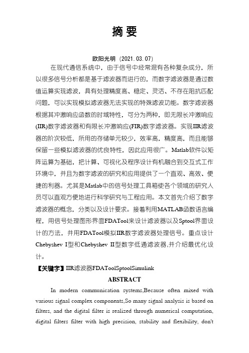
摘要在现代通信系统中,由于信号中经常混有各种复杂成分,所以很多信号分析都是基于滤波器而进行的,而数字滤波器是通过数值运算实现滤波,具有处理精度高、稳定、灵活、不存在阻抗匹配问题,可以实现模拟滤波器无法实现的特殊滤波功能。
数字滤波器根据其冲激响应函数的时域特性,可分为两种,即无限长冲激响应(IIR)数字滤波器和有限长冲激响应(FIR)数字滤波器。
实现IIR滤波器的阶次较低,所用的存储单元较少,效率高,精度高,而且能够保留一些模拟滤波器的优良特性,因此应用很广。
Matlab软件以矩阵运算为基础,把计算、可视化及程序设计有机融合到交互式工作环境中,并且为数字滤波的研究和应用提供了一个直观、高效、便捷的利器。
尤其是Matlab中的信号处理工具箱使各个领域的研究人员可以直观方便地进行科学研究与工程应用。
本文首先介绍了数字滤波器的概念,分类以及设计要求。
接着利用MATLAB函数语言编程,用信号处理图形界面FDATool来设计滤波器以及Sptool 界面设计的方法,并用FDATool模拟IIR数字滤波器处理信号。
重点设计Chebyshev I型和Chebyshev II型数字低通滤波器,并介绍最优化设计。
【关键字】IIR滤波器FDAToolSptoolSimulinkABSTRACTIn modern communication systems,Because often mixed with various signal complex components,So many signal analysis is based on filters, and the digital filter is realized through numerical computation, digital filters filter with high precision, stability and flexibility, don't exist, can realize the impedance matching simulating the special filter cannot achieve filter function. Digital filter according to its impulse response function and characteristics of the time can be divided into two kinds, namely the infinite impulse response (IIR) digital filter and finite impulse response (FIR digital filters). The order of realizing IIR filter is used, low and high efficiency less storage unit, high precision, and can keep some simulation characteristics of filter, so it is widely used. Matlab software based on matrix computation, the calculation, visualization and program design of organic integration to interactiveenvironment for digital filter, and the research and application of provides an intuitive, efficient and convenient tool. Especially in the Matlab signal processing to all areas of research toolbox personnel can easily for scientific research and engineering application. This paper introduces the concept of digital filter, classification and design requirements. Then usingMATLAB language programming, with functions of signal processing FDATool graphical interface design of interface design and Sptool filter, and FDATool analog signal processing IIR digital filter. Key design Chebyshev type I and II digital Chebyshev lowpass filter, and introduces optimization design.【Keywords】 IIR Filter FDATool Sptool Simulink目录前言1第一章数字滤波器2第一节数字滤波器的概念2第二节数字滤波器的分类2第三节数字滤波器的设计要求4第二章 IIR数字滤波器设计方法5第一节 IIR数字滤波器的设计步骤5第二节用脉冲相应不变法设计IIR数字滤波器6一、设计原理6二、脉冲响应不变法优缺点8第三节双线性变换法设计IIR数字滤波器9一、设计原理9二、双线性变换法优缺点11第三章 IIR滤波器的MATLAB设计13第一节 IIR数字滤波器的典型设计法14第二节 IIR数字滤波器的直接设计法18第三节 FDATool介绍和界面设计23第四节 FDATOOL设计IIR数字滤波器24第五节 SIMULINK 仿真IIR滤波器26总结29致谢30参考文献31结束语32前言随着信息时代和数字世界的到来,数字信号处理已成为当今一门极其重要的学科和技术领域。
毕业设计(论文)-基于MATLAB的IIR数字滤波器的设计
IIR数字滤波器的设计摘要数字滤波器是对数字信号进行滤波处理以得到期望的响应特性的离散时间系统。
作为一种电子滤波器,数字滤波器与完全工作在模拟信号域的模拟滤波器不同。
数字滤波器工作在数字信号域,它处理的对象是经由采样器件将模拟信号转换而得到的数字信号。
数字滤波器的工作方式与模拟滤波器也完全不同:后者完全依靠电阻、电容、晶体管等电子元件组成的物理网络实现滤波功能;而前者是通过数字运算器件对输入的数字信号进行运算和处理,从而实现设计要求的特性。
本文由数字滤波器的功能、应用及发展入手,介绍了数字滤波器的基本概念,其中包括系统的描述、系统的传递函数和IIR数字滤波器基本结构。
其次根据IIR数字滤波器的设计原理,在MA TLAB环境下分别采用脉冲响应不变法、双线性变换法和MA TLAB函数直接设计法对IIR数字滤波器进行了设计。
最后应用FDATool和Simulink工具对IIR数字滤波器进行了仿真。
关键词:IIR数字滤波器;MATLAB;脉冲响应不变法;双线性变换法;FDATool;SimulinkDesign of IIR digital filterAbstractDigital filters are the discrete-time systems that process to filter digital signal to get expected response characteristics. As an electronic filter, digital filters work differently from the analog signal filters who completely work in analogy signal domain. Digital filter work in the digital signal domain and its targets are digital signals that are received by sampling devices converting analog signals to digital signals. The working methods of digital filters and analog filters are completely different: the latter completely rely on the function of the physical network formed by resistors, capacitors, transistors and other electronic components of filtering ,while the former computes and processes digital signals with the help of digital computing devices to realize the characteristics of the design requirements.In this paper, the function, application and development of the digital filter are introduced followed by the introduction of the principle of digital filter design. The principle first includes the description of the system, the transfer function of the system and the basic structure of the IIR (Infinite Impulse Response) digital filter. Then, according to the design principle of IIR digital filter, the IIR digital filter is designed by the method of non-changing impulse response, the method of double linear transform and direct method using MATLAB functions. At last, the designed IIR digital filter is simulated by FDATool and MATLAB Simulink Tool.Key words:IIR digital filter;MATLAB;non-changing impulse response;double linear transformation;FDATool;Simulink目录第一章绪论 (1)1.1数字滤波器技术概述 (1)1.2滤波器及滤波方法的发展历程 (2)1.3滤波器的分类 (3)1.4数字滤波器的优越性 (4)1.5数字滤波器的实现方法 (5)1.6MATLAB软件简介 (6)1.7MATLAB的语言特点 (8)第二章数字滤波器基础 (10)2.1数字滤波器的基本概念 (10)2.2系统的描述 (11)2.3系统的传递函数 (12)2.4IIR数字滤波器的基本结构 (12)2.4.1直接Ⅰ型 (13)2.4.2直接Ⅱ型 (14)2.4.3级联型 (14)2.4.4并联型 (16)第三章IIR数字滤波器的设计方法及过程 (17)3.1基于脉冲响应不变法的IIR滤波器设计 (17)3.2基于双线性Z变换法的IIR滤波器设计 (20)3.3基于MATLAB函数直接设计IIR数字滤波器 (24)3.3.1巴特沃斯数字滤波器设计 (24)3.3.2切比雪夫Ⅰ型IIR数字滤波器设计 (27)3.3.3切比雪夫Ⅱ型IIR数字滤波器设计 (29)3.3.4基于椭圆法直接设计IIR数字滤波器 (30)3.4FDAT OOL设计法 (33)3.5S IMULINK建模设计法 (37)第四章结论 (41)参考文献 (42)致谢 (43)第一章绪论1.1 数字滤波器技术概述数字滤波器实际上就是一种数字信号处理系统的算法或设备,也可以说是一种运算过程。
基于Matlab的IIR数字滤波器设计
机械与电子 2011( 1)
基于 M atlab 的 IIR 数字滤 波器设计
自动控制与检测
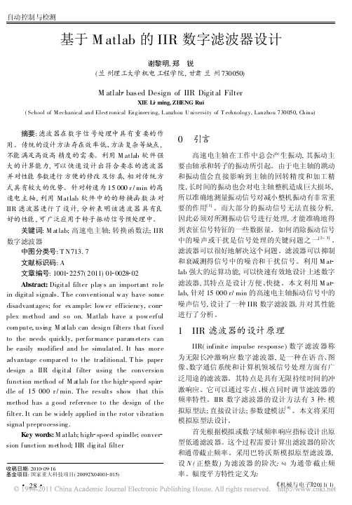
电主轴的最高转速 15 000 r/ m in, 即最高转速 为 250 r/ s, 设采样频率 f s= 1 kH z, 通带频率 f p = 100 H z, 通带 衰减 小于 1 dB, 阻 带 频率 f st = 200 H z, 阻带衰减大于 50 dB。利用双线性变换法设计 巴特沃思型数字低通滤波器。运行结果为 N ( 滤波 器阶数) = 8 W n( 截止频率) = 707. 605 7。M 文件 程序代码如下:
29
自动控制与检测
薄壁零件受力分析实验数据自动采集装置的设计
付延召, 周燕飞 ( 南京航空航天大学机电学院, 江苏 南京 210016)
Design of Autom atic Dat a Acquisition Device for Analysis of T hin W alled Com ponent s
关键词: M at lab; 高速电主轴; 转换函数法; IIR 数字滤波器
中图分类号: T N713. 7 文献标识码: A 文章编号: 1001 2257( 2011) 01 0028 02 Abstract: Digit al filt er play s an import ant ro le in digit al signals. T he convent ional w ay have som e disadvant ages; for ex ample: low er eff iciency, com plex m et hod and so on. Mat lab have a pow erf ul com put e, using M at lab can desig n f ilt ers t hat f ixed to the needs quickly, per for mance param et ers can be easily modified and be simulat ed. It has mor e advantage compar ed t o t he tr aditional. T his paper design a IIR dig it al f ilter using t he conversio n funct ion method of M at lab f or t he high speed spin dle of 15 000 r / min. T he result s show t hat t his method has a g ood ref erence t o t he design of t he filt er. It can be w idely applied in t he rot or vibrat io n signal prepro cessing . Key words: M at lab; high speed spindle; conver sion f unct ion m et hod; IIR dig ital filt er
基于matlab数字滤波器的设计
摘要:利用MATLAB 设计滤波器,可以按照设计要求非常方便地调整设计参数,极大地减轻了设计的工作量,有利于滤波器设计的最优化。
Matlab因其强大的数据处理功能被广泛应用于工程计算,其丰富的工具箱为工程计算提供了便利,利用Matlab信号处理工具箱可以快速有效地设计各种数字滤波器,设计简单方便。
本文介绍了在MATLAB R2009a 环境下滤波器设计的方法和步骤。
关键词:滤波器,matlab,fdatoolAbstract:By using MATLAB , we can design filters and modify the filters’parameters conveniently according to our demands. This relieves greatly design work loads and makes for optimization of filter designing. Matlab can be widely used in engineering calculations because of its powerful functions of data processing. Its rich toolbox makes the calculations easy. With Matlab signal processing toolbox, various digital filters can be designed effectively in simple way. This article introduce the methods and processes in the circumstance of MATLAB R2009a.Keywords:filter,matlab,fdatool目录1 引言: (5)2 滤波器简介 (6)2.1滤波器的概念 (6)2.2 滤波器的发展过程 (6)2.3 滤波器的原理 (7)2.4滤波器的分类 (8)3 MATLAB简介 (10)3.1 MATLAB的概况 (10)3.2 MATLAB产生的历史背景 (11)3.3 MATLAB的语言特点 (12)3.4 MTALAB的功能 (13)4 方案设计 (16)4.1巴特沃斯IIR滤波器的设计 (16)4.2 契比雪夫I型IIR滤波器的设计 (16)4.3数字滤波器的设计 (17)4.4数字滤波器simulink仿真及实现 (27)结论 (31)参考文献 (32)致谢......................................................................................................... 错误!未定义书签。
基于Matlab的IIR数字滤波器设计(论文)
摘要在现代通信系统中,由于信号中经常混有各种复杂成分,所以很多信号分析都是基于滤波器而进行的,而数字滤波器是通过数值运算实现滤波,具有处理精度高、稳定、灵活、不存在阻抗匹配问题,可以实现模拟滤波器无法实现的特殊滤波功能。
数字滤波器根据其冲激响应函数的时域特性,可分为两种,即无限长冲激响应(IIR)数字滤波器和有限长冲激响应(FIR)数字滤波器。
实现IIR滤波器的阶次较低,所用的存储单元较少,效率高,精度高,而且能够保留一些模拟滤波器的优良特性,因此应用很广。
Matlab软件以矩阵运算为基础,把计算、可视化及程序设计有机融合到交互式工作环境中,并且为数字滤波的研究和应用提供了一个直观、高效、便捷的利器。
尤其是Matlab中的信号处理工具箱使各个领域的研究人员可以直观方便地进行科学研究与工程应用。
本文首先介绍了数字滤波器的概念,分类以及设计要求。
接着利用MATLAB函数语言编程,用信号处理图形界面FDATool来设计滤波器以及Sptool界面设计的方法,并用FDATool模拟IIR 数字滤波器处理信号。
重点设计Chebyshev I型和Chebyshev II型数字低通滤波器,并介绍最优化设计。
【关键字】IIR 滤波器FDATool Sptool SimulinkABSTRACTIn modern communication systems,Because often mixed with various signal complex components,So many signal analysis is based on filters, and the digital filter is realized through numerical computation, digital filters filter with high precision, stability and flexibility, don't exist, can realize the impedance matching simulating the special filter cannot achieve filter function. Digital filter according to its impulse response function and characteristics of the time can be divided into two kinds, namely the infinite impulse response (IIR) digital filter and finite impulse response (FIR digital filters). The order of realizing IIR filter is used, low and high efficiency less storage unit, high precision, and can keep some simulation characteristics of filter, so it is widely used. Matlab software based on matrix computation, the calculation, visualization and program design of organic integration to interactive environment for digital filter, and the research and application of provides an intuitive, efficient and convenient tool. Especially in the Matlab signal processing to all areas of research toolbox personnel can easily for scientific research and engineering application. This paper introduces the concept of digital filter, classification and design requirements. Then using MATLAB language programming, with functions of signal processing FDATool graphical interface design of interface design and Sptool filter, and FDATool analog signal processing IIR digital filter. Key design Chebyshev type I and II digital Chebyshev lowpass filter, and introduces optimization design.【Keywords】IIR Filter FDATool Sptool Simulink目录前言 ............................................................. 1第一章数字滤波器 ................................................. 2第一节数字滤波器的概念........................................ 2第二节数字滤波器的分类........................................ 2第三节数字滤波器的设计要求.................................... 4第二章 IIR数字滤波器设计方法...................................... 5第一节 IIR数字滤波器的设计步骤................................. 5第二节用脉冲相应不变法设计IIR数字滤波器...................... 6一、设计原理................................................ 6二、脉冲响应不变法优缺点.................................... 8第三节双线性变换法设计IIR数字滤波器.......................... 9一、设计原理................................................ 9二、双线性变换法优缺点.................................... 11第三章 IIR滤波器的MATLAB设计................................... 13第一节 IIR数字滤波器的典型设计法............................. 14第二节 IIR数字滤波器的直接设计法............................. 18第三节 FDATool介绍和界面设计................................. 23第四节 FDATOOL设计IIR数字滤波器............................. 24第五节 SIMULINK 仿真IIR滤波器............................... 26总结 ........................................................... 29致谢 ........................................................... 30参考文献 ........................................................ 31结束语 .......................................................... 32前言随着信息时代和数字世界的到来,数字信号处理已成为当今一门极其重要的学科和技术领域。
基于MATLAB的FIR和IIR数字滤波器的设计

基于MATLAB的FIR和IIR数字滤波器的设计一、本文概述随着数字信号处理技术的飞速发展,数字滤波器作为其中的核心组件,已经广泛应用于通信、音频处理、图像处理、生物医学工程等诸多领域。
在数字滤波器中,有限脉冲响应(FIR)滤波器和无限脉冲响应(IIR)滤波器是最常见的两种类型。
它们各自具有独特的优点和适用场景,因此,对这两种滤波器的深入理解和设计掌握是工程师和研究人员必备的技能。
本文旨在通过MATLAB这一强大的工程计算工具,详细介绍FIR 和IIR数字滤波器的设计原理、实现方法以及对比分析。
我们将简要回顾数字滤波器的基本概念和分类,然后重点阐述FIR和IIR滤波器的设计理论,包括窗函数法、频率采样法、最小均方误差法等多种设计方法。
接下来,我们将通过MATLAB编程实现这些设计方法,并展示如何根据实际应用需求调整滤波器参数以达到最佳性能。
本文还将对FIR和IIR滤波器进行性能对比,分析它们在不同应用场景下的优缺点,并提供一些实用的设计建议。
我们将通过几个典型的应用案例,展示如何在MATLAB中灵活应用FIR和IIR滤波器解决实际问题。
通过阅读本文,读者将能够深入理解FIR和IIR数字滤波器的设计原理和实现方法,掌握MATLAB在数字滤波器设计中的应用技巧,为未来的工程实践和研究工作打下坚实的基础。
二、FIR滤波器设计有限脉冲响应(FIR)滤波器是一种数字滤波器,其特点是其脉冲响应在有限的时间后为零。
因此,FIR滤波器是非递归的,没有反馈路径,从而保证了系统的稳定性。
在设计FIR滤波器时,我们主要关注的是滤波器的阶数、截止频率和窗函数的选择。
在MATLAB中,有多种方法可以用来设计FIR滤波器。
其中,最常用的方法是使用fir1函数,该函数可以设计一个线性相位FIR滤波器。
该函数的基本语法是b = fir1(n, Wn),其中n是滤波器的阶数,Wn是归一化截止频率,以π为单位。
该函数返回一个长度为n+1的滤波器系数向量b。
基于matlab的IIR数字滤波器的设计毕业设计(论文)
基于matlab的IIR数字滤波器的设计摘要:IIR数字滤波器在MATLAB环境下的设计方法和实现方法,在无限脉冲响应(IIR)数字滤波器设计中,先进行模拟滤波器的设计,然后进行模拟—数字滤波器转换,即采用脉冲响应不变法及双线性Z变化法设计数字滤波器,最后进行滤波器的频带转换。
关键词:IIR数字滤波器;matlab;频带转换;引言数字滤波器是数字信号处理的重要基础,数字信号处理主要是研究数字或符号的序列表示信号波形,并用数字的方式去处理这些序列,把它们改变成在某分量和中意义上更希望的形式,以便估计信号的特征参量,或削弱信号中的多余分量和增强信号中的有用分量。
数字滤波器在对信号的过滤、检测与参数估计等处理过程中,是使用最为广泛的一种线性系统。
滤波器的种类很多,从功能上可以分为低通、高通、带通和带阻滤波器,上述每种滤波器又可以分为模拟滤波器和数字滤波器。
如果滤波器的输入输出都是数字信号,则这样的滤波器称之为数字滤波器,它通常通过一定的运算关系改变输入信号所含频率成分的相对比例或者滤除某些频率成分来实现滤波。
根据数字滤波器冲激响应的时域特性,可将数字滤波器分为两种,即无限长冲激响应(IIR)滤波器和有限长冲激响应(FIR)滤波器。
有数字信号处理的一般理论可知,IIR 滤波器的特征是具有无限持续时间的冲激响应,而FIR滤波器使冲激响应只能持续一定的时间。
随着信息时代的到来,数字信号处理已经成为当今一门极其重要的学科和技术,并且在通信、语音、图像、自动控制等众多领域得到了广泛的应用。
在数字信号处理中,数字滤波器占有极其重要的地位,它具有精度高、可靠性好、灵活性大等特点。
现代数字滤波器可以用软件或硬件两种方式来实现。
软件方式实现的优点是可以通过滤波器参数的改变去调整滤波器的性能。
MATLAB是一种面向科学和工程计算的语言,它集数值分析、矩阵运算、信号处理和图形显示于一体,具有编程效率高、调试手段丰富、扩充能力强等特点。
基于MATLAB的IIR数字滤波器的设计及应用

IIR滤波器设计方法有两类,经常用到的一类设计方法是借助于模拟滤波器的设计方法进行的。其设计思路是:先设计模拟滤波器得到传输函数 ,然后将 按某种方法转换为数字滤波器的系统函数 。这一类方法是基于模拟滤波器的设计方法相对比较成熟,它不仅有完整的设计公式,也有完整的图标供查阅,更可以直接调用MATLAB中的对应的函数进行设计。另一种是直接在频域或者时域中进行设计,设计时必须使用计算机辅助,直接调用MATLAB中的程序或函数即可设计。
附录B程序清单33
第
数字滤波是数字信号处理的重要基础,数字信号处理主要是研究用数字或符号的序列来表示信号波形,并用数字的方式去处理这些序列,把它们改变成在某种意义上更希望的形式,以便估计信号的特征参量,或削弱信号中的多余分量和增强信号中的有用分量。数字滤波器在对信号的过滤、检测与参数估计等处理过程中,是使用最为广泛的一种线性系统。
Digital filter uses discrete system characteristics to conduct processing and transformation to the system input signal, change the input sequence spectrum or signal waveform, let the useful frequency components through, inhibit the outputing of unwanted signal components. Industrial parts throughout our daily necessities, but in the processing of industrial parts often appears scratches, abrasions, mark phenomenon, in order to collection qualified industrial parts effectively,using digital filter analysis to noise forms (such as salt and pepper noise) simulating the acquisition of industrial parts of the dust, mark, followed by the de-noising and filtering to obtain the purpose of qualified parts.
基于Matlab的IIR数字滤波器设计(论文)
在现代通信系统中,由于信号中经常混有各种复杂成分,所以很多信号分析都是基于滤波器而进行的,而数字滤波器是通过数值运算实现滤波,具有处理精度高、稳定、灵活、不存在阻抗匹配问题,可以实现模拟滤波器无法实现的特殊滤波功能。
数字滤波器根据其冲激响应函数的时域特性,可分为两种,即无限长冲激响应(IIR)数字滤波器和有限长冲激响应(FIR)数字滤波器。
实现IIR滤波器的阶次较低,所用的存储单元较少,效率高,精度高,而且能够保留一些模拟滤波器的优良特性,因此应用很广。
Matlab软件以矩阵运算为基础,把计算、可视化及程序设计有机融合到交互式工作环境中,并且为数字滤波的研究和应用提供了一个直观、高效、便捷的利器。
尤其是Matlab中的信号处理工具箱使各个领域的研究人员可以直观方便地进行科学研究与工程应用。
本文首先介绍了数字滤波器的概念,分类以及设计要求。
接着利用MATLAB函数语言编程,用信号处理图形界面FDATool来设计滤波器以及Sptool界面设计的方法,并用FDATool 模拟IIR 数字滤波器处理信号。
重点设计Chebyshev I型和Chebyshev II型数字低通滤波器,并介绍最优化设计。
关键字】IIR 滤波器FDATool Sptool SimulinkABSTRACTIn modern communication systems, Because often mixed with various signal complex components, So many signal analysis is based on filters, and the digital filter is realized through numerical computation, digital filters filter with high precision, stability and flexibility, don't exist, can realize the impedance matching simulating the special filter cannot achieve filter function. Digital filter according to its impulse response function and characteristics of the time can be divided into two kinds, namely the infinite impulse response (IIR) digital filter and finite impulse response (FIR digital filters). The order of realizing IIR filter is used, low and high efficiency less storage unit, high precision, and can keep some simulation characteristics of filter, so it is widely used. Matlab software based on matrix computation, the calculation, visualization and program design of organic integration to interactive environment for digital filter, and the research and application of provides an intuitive, efficient and convenient tool. Especially in the Matlab signal processing to all areas of research toolbox personnel can easily for scientific research and engineering application. This paper introduces the concept of digital filter, classification and design requirements. Then using MATLAB language programming, with functions of signal processing FDATool graphical interface design of interface design and Sptool filter, and FDATool analog signal processing IIR digital filter. Key design Chebyshev type I and II digital Chebyshev lowpass filter, and introduces optimization design.【Keywords】IIR Filter FDATool Sptool Simulink目录前言............................................................ 1第一章数字滤波器................................................ 2第一节数字滤波器的概念 ...................................... 2第二节数字滤波器的分类 ...................................... 2第三节数字滤波器的设计要求 .................................. 4第二章 IIR 数字滤波器设计方法.................................... 5第一节 IIR 数字滤波器的设计步骤 .............................. 5第二节用脉冲相应不变法设计 IIR数字滤波器.................... 6一、设计原理............................................... 6二、脉冲响应不变法优缺点.................................. 8第三节双线性变换法设计 IIR数字滤波器........................ 9一、设计原理............................................... 9二、双线性变换法优缺点.................................. 11第三章 IIR滤波器的 MATLAB设计................................. 13第一节 IIR 数字滤波器的典型设计法 ........................... 14第二节 IIR 数字滤波器的直接设计法 .......................... 18第三节 FDATool 介绍和界面设计 .............................. 23第四节 FDATOOL 设计IIR 数字滤波器.......................... 24第五节 SIMULINK 仿真 IIR滤波器............................. 26总结.......................................................... 29致谢.......................................................... 30参考文献....................................................... 31结束语......................................................... 32前言随着信息时代和数字世界的到来,数字信号处理已成为当今一门极其重要的学科和技术领域。
基于Matlab的IIR Butterworth低通数字滤波器设计
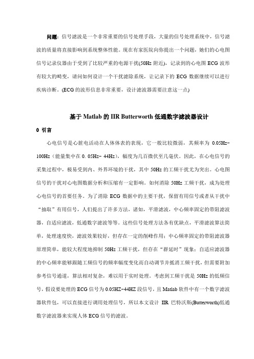
问题:信号滤波是一个非常重要的信号处理手段,大量的信号处理系统中,信号滤波的质量将直接影响到系统整体性能。
现在有家医院向你提出一个问题,她们的心电图信号记录仪器由于受到了比较严重的电源干扰(50Hz附近),记录到的心电图ECG波形有较大的畸变,请问如何设计一个干扰滤除系统,让记录下的ECG数据继续可以进行疾病诊断。
(ECG的波形信息非常重要,设计滤波器需要注意这一点)基于Matlab的IIR Butterworth低通数字滤波器设计0 引言心电信号是心脏电活动在人体体表的表现,它一般比较微弱,其频率为0.05Hz~ 100Hz(能量集中在0. 05Hz~ 44Hz),幅度为几百微伏至几毫伏。
因此,在心电信号的采集过程中,极易受到内、外界环境的干扰,其中50Hz的工频干扰尤为突出。
心电图信号的干扰对心电图数据分析和压缩有一定影响。
如何消除50Hz工频干扰,成为处理心电信号的首要任务。
为了消除ECG数据中的主要干扰,保留有用信号或者从干扰中“抽取”有用信号,人们提出了许多方法,诸如,平滑滤波,中心频率固定的带阻滤波器,自适应滤波,低通数字滤波等等。
这些信号处理方法各有优缺点,平滑滤波算法简单,处理速度快,滤波效果较好,但存在一定的削峰作用;中心频率固定的带阻滤波器原理简单,能较大程度地抑制50Hz工频干扰,但存在“群延时”现象;自适应滤波器的中心频率能够跟随工频信号的频率幅度变化而自动调节并抵消工频干扰,但需要附加参考信号通道,算法相对复杂,难以用于实时处理。
考虑到工频干扰是50Hz的低频信号,假设要处理的ECG信号为0.05HZ~44HZ段信号,且Matlab软件中有一个数字滤波器软件包,可以直接进行调用处理信号,所以本文设计IIR巴特沃斯(Butterworth)低通数字滤波器来实现人体ECG信号的滤波。
1 数字滤波器介绍数字滤波器是一种用来过滤时间离散信号的数字系统,它可以用软件(计算机程序)或用硬件来实现,而且在两种情况下都可以用来过滤实时信号或非实时信号(记录信号)。
基于matlab的IIR数字滤波器设计

基于matlab的IIR数字滤波器设计一.IIR数字滤波器介绍1.IIR数字滤波器的根本原理所谓数字滤波器,是指输入,输出均为数字信号,通过一定运算关系改变输入信号所含频率成分的相比照例或者滤除某些频率成分的硬件。
实质上就是一个由有限精度算法实现的线性时不变离散系统。
它的根本工作原理是利用离散系统的特性对系统输入信号进展加工和变换,改变输入序列的频谱或信号波形,让有用的频率分量通过,抑制无用的信号分量输出,因此数字滤波与模拟滤波的概念一样,根据其频率特性同样可以分为低通,高通,带通,带阻,只是信号的形式和实现滤波方式有所不同。
如果要处理的信号是模拟信号,就可以通过A/D或者D/A转换,在信号形式上进展匹配转换,同样可以使用数字滤波器对模拟信号进展滤波。
数字滤波器滤波的数学表达式:y〔n〕=x(n)*h(n); 如果滤波器的输入输出信号都是离散信号,那么该滤波器的脉冲响应也一定是离散信号,这样的滤波器就成为了数字滤波器。
上面的系统为时域离散系统时,其频域特性为:其中分别是数字滤波器的输出序列和输入序列的频域响应,是数字滤波器的频域响应。
可以看见按照输入信号的频谱特点和处理信号的目的适中选择滤波器的频域响应,使得滤波后的输出信号满足设计性能要求,就是滤波器的滤波原理。
2.IIR数字滤波器传输特性IIR数字滤波器的系统函数可以表示为:H(Z)=,式中H(Z)称为N阶IIR滤波器函数。
3..数字滤波器的技术要求.我们通常设计的数字滤波器一般属于选频滤波器,。
我们的目的是要设计一个因果可实现的滤波器,另外买也要考虑到本钱和复杂性问题,因此实用中通带和阻带都允许一定的误差容限,即通带不一定是完全水平的,阻带也不可能完全衰减到零。
而且,通带和阻带之间还要设置一定带宽的过渡带。
如如下图表示低通滤波器的技术要求:图中,分别表示通带截止频率和阻带截止频率,通带频率范围为0≤w≤,通带中要求〔1-δ1〕≤|H≤1,阻带截止频率范围≤w≤Π,再阻带中要求≤δ2,从p w 到s w 称为过渡带,在这个频带内,幅度响应从通带平滑的下落到阻带。
Matlab滤波器设计--IIR滤波器的设计与仿真

matlab滤波器设计-IIR滤波器的设计与仿真1 引言在现代通信系统中,由于信号中经常混有各种复杂成分,所以很多信号的处理和分析都是基于滤波器而进行的。
但是,传统的数字滤波器的设计使用繁琐的公式计算,改变参数后需要重新计算,从而在设计滤波器尤其是高阶滤波器时工作量很大。
利用MATLAB信号处理箱(Signal Processing Toolbox)可以快速有效地实现数字滤波器的设计与仿真。
2 数字滤波器及传统设计方法数字滤波器可以理解为是一个计算程序或算法,将代表输入信号的数字时间序列转化为代表输出信号的数字时间序列,并在转化过程中,使信号按预定的形式变化。
数字滤波器有多种分类,根据数字滤波器冲激响应的时域特征,可将数字滤波器分为两种,即无限长冲激响应(IIR)滤波器和有限长冲激响应(FIR)滤波器。
IIR数字滤波器具有无限宽的冲激响应,与模拟滤波器相匹配,所以IIR滤波器的设计可以采取在模拟滤波器设计的基础上进一步变换的方法。
其设计方法主要有经典设计法、直接设计法和最大平滑滤波器设计法。
FIR数字滤波器的单位脉冲响应是有限长序列。
它的设计问题实质上是确定能满足所要求的转移序列或脉冲响应的常数问题,设计方法主要有窗函数法、频率采样法和等波纹最佳逼近法等。
在对滤波器实际设计时,整个过程的运算量是很大的。
设计阶数较高的IIR滤波器时,计算量更大,设计过程中改变参数或滤波器类型时都要重新计算。
设计完成后对已设计的滤波器的频率响应要进行校核。
要得到幅频、相频响应特性,运算量也是很大的。
平时所要设计的数字滤波器,阶数和类型并不一定是完全给定的,很多时候要根据设计要求和滤波效果不断地调整,以达到设计的最优化。
在这种情况下,滤波器设计就要进行大量复杂的运算,单纯的靠公式计算和编制简单的程序很难在短时间内完成。
利用MATLAB强大的计算功能进行计算机辅助设计,可以快速有效地设计数字滤波器,大大地简化了计算量。
matlab-滤波器-外文翻译-外文文献-英文文献-IIR数字滤波器的设计
IIR Digital Filter DesignAn important step in the development of a digital filter is the determination of a realizable transfer function G(z) approximating the given frequency response specifications. If an IIR filter is desired,it is also necessary to ensure that G(z) is stable. The process of deriving the transfer function G(z) is called digital filter design. After G(z) has been obtained, the next step is to realize it in the form of a suitable filter structure. In chapter 8,we outlined a variety of basic structures for the realization of FIR and IIR transfer functions. In this chapter,we consider the IIR digital filter design problem. The design of FIR digital filters is treated in chapter 10.First we review some of the issues associated with the filter design problem. A widely used approach to IIR filter design based on the conversion of a prototype analog transfer function to a digital transfer function is discussed next. Typical design examples are included to illustrate this approach. We then consider the transformation of one type of IIR filter transfer function into another type, which is achieved by replacing the complex variable z by a function of z. Four commonly used transformations are summarized. Finally we consider the computer-aided design of IIR digital filter. To this end, we restrict our discussion to the use of matlab in determining the transfer functions.9.1 preliminary considerationsThere are two major issues that need to be answered before one can develop the digital transfer function G(z). The first and foremost issue is the development of a reasonable filter frequency response specification from the requirements of the overall system in which the digital filter is to be employed. The second issue is to determine whether an FIR or IIR digital filter is to be designed. In the section ,we examine these two issues first . Next we review the basic analytical approach to the design of IIR digital filters and then consider the determination of the filter order that meets the prescribed specifications. We also discuss appropriate scaling of the transfer function.9.1.1 Digital Filter SpecificationsAs in the case of the analog filter,either the magnitude and/or the phase(delay) response is specified for the design of a digital filter for most applications. In some situations, the unit sample response or step response may be specified. In most practical applications, the problem of interest is the development of a realizable approximation to a given magnitude response specification. As indicated in section 4.6.3, thephase response of the designed filter can be corrected by cascading it with an allpass section. The design of allpass phase equalizers has received a fair amount of attention in the last few years.We restrict our attention in this chapter to the magnitude approximation problem only. We pointed out in section 4.4.1 that there are four basic types of filters,whose magnitude responses are shown in Figure 4.10. Since the impulse response corresponding to each of these is noncausal and of infinite length, these ideal filters are not realizable. One way of developing a realizable approximation to these filter would be to truncate the impulse response as indicated in Eq.(4.72) for a lowpass filter. The magnitude response of the FIR lowpass filter obtained by truncating the impulse response of the ideal lowpass filter does not have a sharp transition from passband to stopband but, rather, exhibits a gradual "roll-off."Thus, as in the case of the analog filter design problem outlined in section 5.4.1, the magnitude response specifications of a digital filter in the passband and in the stopband are given with some acceptable tolerances. In addition, a transition band is specified between the passband and the stopband to permit the magnitude to drop off smoothly. For example, the magnitude )(ωj e G of a lowpass filter may be given as shown in Figure 7.1. As indicated in the figure, in the passband defined by 0p ωω≤≤, we require that the magnitude approximates unity with an error of p δ±,i.e.,p p j p for e G ωωδδω≤+≤≤-,1)(1.In the stopband, defined by πωω≤≤s ,we require that the magnitude approximates zero with an error of i s ,δ.e.,,)(s j e G δω≤ forπωω≤≤s . The frequencies p ω and s ω are , respectively, called the passband edge frequency and the stopbandedge frequency. The limits of the tolerances in the passband and stopband,p δ and s δ, are usually called the peak ripple values. Note that the frequency response )(ωj e G of a digital filter is a periodicfunction of ω,and the magnitude response of a real-coefficient digital filter is an even function of ω. As a result, the digital filter specifications are given only for the range πω≤≤0.Digital filter specifications are often given in terms of the loss function,)(log 20)(10ωωζj e G -=,in dB. Here the peak passband ripple p α and the minimum stopband attenuation s α are given in dB,i.e., the loss specifications of a digital filter are given bydB p p )1(log 2010δα--=,dB s s )(log 2010δα-=.9.1 Preliminary ConsiderationsAs in the case of an analog lowpass filter, the specifications for a digital lowpass filter may alternatively be given in terms of its magnitude response, as in Figure 7.2. Here the maximum value of the magnitude in the passband is assumed to be unity, and the maximum passband deviation, denoted as 1/21ε+,is given by the minimum value of the magnitude in the passband. The maximum stopband magnitude is denoted by 1/A.For the normalized specification, the maximum value of the gain function or the minimum value of the loss function is therefore 0 dB. The quantity max α given byIs called the maximum passband attenuation. Forp δ<<1, as is typically the case, it can be shown thatThe passband and stopband edge frequencies, in most applications, are specified in Hz, along with the sampling rate of the digital filter. Since all filter design techniques are developed in terms of normalized angular frequencies p ω and s ω,the sepcified critical frequencies need to be normalized before a specific filter design algorithm can be applied. Let T F denote the sampling frequency in Hz, and F P and F s denote, respectively,the passband and stopband edge frequencies in Hz. Then the normalized angular edge frequencies in radians are given by9.1.2 Selection of the Filter TypeThe second issue of interest is the selection of the digital filter type,i.e.,whether an IIR or an FIR digital filter is to be employed. The objective of digital filter design is to develop a causal transfer function H(z) meeting the frequency response specifications. For IIR digital filter design, the IIR transfer function is a real rational function of 1-z . H(z)=N MdNzz d z d d pMz z p z p p ------++++++++ (2211022110)Moreover, H(z) must be a stable transfer function, and for reduced computational complexity, it must be of lowest order N. On the other hand, for FIR filter design, the FIR transfer function is a polynomial in 1 z :For reduced computational complexity, the degree N of H(z) must be as small as possible. In addition, if a linear phase is desired, then the FIR filter coefficients must satisfy the constraint:T here are several advantages in using an FIR filter, since it can be designed with exact linear phase and the filter structure is always stable with quantized filter coefficients. However, in most cases, the order N FIR of an FIR filter is considerably higher than the order N IIR of an equivalent IIR filter meeting the same magnitude specifications. In general, the implementation of the FIR filter requires approximately N FIR multiplications per output sample, whereas the IIR filter requires 2N IIR +1 multiplications per output sample. In the former case, if the FIR filter is designed with a linear phase, then the number of multiplications per output sample reduces to approximately (N FIR +1)/2. Likewise, most IIR filter designs result in transfer functions with zeros on the unit circle, and the cascade realization of an IIR filter of order IIR N with all of the zeros on the unit circle requires [(3IIR N +3)/2] multiplications per output sample. It has been shown that for most practical filter specifications, the ratio N FIR /N IIR is typically of the order of tens or more and, as a result, the IIR filter usually is computationally more efficient[Rab75]. However ,if the group delay of the IIR filter is equalized by cascading it with an allpass equalizer, then the savings in computation may no longer be that significant [Rab75]. In many applications, the linearity of the phase response of the digital filter is not an issue,making the IIR filter preferable because of the lower computational requirements.9.1.3 Basic Approaches to Digital Filter DesignIn the case of IIR filter design, the most common practice is to convert the digital filter specifications into analog lowpass prototype filter specifications, and then to transform it into the desired digital filter transfer function G(z). This approach has been widely used for many reasons:(a) Analog approximation techniques are highly advanced.(b) They usually yield closed-form solutions.(c) Extensive tables are available for analog filter design.(d) Many applications require the digital simulation of analog filters.In the sequel, we denote an analog transfer function as)()()(s D s P s H a a a =, Where the subscript "a" specifically indicates the analog domain. The digital transfer function derived form H a (s) is denoted byThe basic idea behind the conversion of an analog prototype transfer function H a (s) into a digital IIR transfer function G(z) is to apply a mapping from the s-domain to the z-domain so that the essential properties of the analog frequency response are preserved. The implies that the mapping function should be such that(a) The imaginary(j Ω) axis in the s-plane be mapped onto the circle of the z-plane.(b) A stable analog transfer function be transformed into a stable digital transfer function.To this end,the most widely used transformation is the bilinear transformation described in Section 9.2. Unlike IIR digital filter design,the FIR filter design does not have any connection with the design of analog filters. The design of FIR filter design does not have any connection with the design of analog filters. The design of FIR filters is therefore based on a direct approximation of the specified magnitude response,with the often added requirement that the phase response be linear. As pointed out in Eq.(7.10), a causal FIR transfer function H(z) of length N+1 is a polynomial in z -1 of degree N. The corresponding frequency response is given by∑=-=N n n j j en h e H 0][)(ωω.It has been shown in Section 3.2.1 that any finite duration sequence x[n] of length N+1 is completely characterized by N+1 samples of its discrete-time Fourier transfer X(ωj e ). As a result, the design of an FIR filter of length N+1 may be accomplished by finding either the impulse response sequence {h[n]} or N+1 samples of its frequency response )H(e j ω. Also, to ensure a linear-phase design, the condition of Eq.(7.11) must be satisfied. Two direct approaches to the design of FIR filters are the windowed Fourier series approach and the frequency sampling approach. We describe the former approach in Section 7.6. The second approach is treated in Problem 7.6. In Section 7.7 we outline computer-based digital filter design methods.作者:Sanjit K.Mitra国籍:USA出处:Digital Signal Processing -A Computer-Based Approach 3eIIR数字滤波器的设计在一个数字滤波器发展的重要步骤是可实现的传递函数G(z)的接近给定的频率响应规格。
基于IIR数字滤波器的设计matlab毕业设计(含源文件)

引言MATLAB是矩阵实验室(Matrix Laboratory)的简称,是美国MathWorks公司出品的商业数学软件,用于算法开发、数据可视化、数据分析以及数值计算的高级技术计算语言和交互式环境,主要包括MATLAB和Simulink两大部分。
MATLAB和Mathematica、Maple并称为三大数学软件。
它在数学类科技应用软件中在数值计算方面首屈一指。
MATLAB可以进行矩阵运算、绘制函数和数据、实现算法、创建用户界面、连接其他编程语言的程序等,主要应用于工程计算、控制设计、信号处理与通讯、图像处理、信号检测、金融建模设计与分析等领域。
MATLAB的基本数据单位是矩阵,它的指令表达式与数学、工程中常用的形式十分相似,故用MATLAB来解算问题要比用C,FORTRAN等语言完成相同的事情简捷得多,并且mathwork也吸收了像Maple等软件的优点,使MATLAB成为一个强大的数学软件。
在新的版本中也加入了对C,FORTRAN,C++ ,JAVA的支持。
可以直接调用,用户也可以将自己编写的实用程序导入到MATLAB函数库中方便自己以后调用,此外许多的MATLAB爱好者都编写了一些经典的程序,用户可以直接进行下载就可以用MATLAB语言是一种面向科学与工程计算的高级语言,它集科学计算,自动控制,信号处理、神经网络和图象处理等于一体,具有极高的编程效率。
它是一个高级的数学分析与运算软件,可用作动态系统的建模与仿真。
I I R数字滤波器的设计正文一、MATLAB语言的简介1、MATLAB的特点及优势MATLAB作为一种使用广泛的数学软件,具有强大的编程能力,可以进行矩阵的运算、绘制函数和数据,实现算法、创建用户界面、连接其他编程语言的程序等。
它具有以下几个显著特点:●此高级语言可用于技术计算●此开发环境可对代码、文件和数据进行管理●交互式工具可以按迭代的方式探查、设计及求解问题●数学函数可用于线性代数、统计、傅立叶分析、筛选、优化以及数值积分等●二维和三维图形函数可用于可视化数据●各种工具可用于构建自定义的图形用户界面●各种函数可将基于MATLAB的算法与外部应用程序和语言(如C、C++、Fortran、Java、COM 以及Microsoft Excel)集成●不支持大写输入,内核仅仅支持小写同时MATLAB和Mathematica、Maple并称为三大数学软件,自然有它的显著优势,以下简单的介绍它的优势。
matlabIIR数字滤波器
数字滤波器(DIGI tal Filter)是指输入、输出都是离散时间信号,通过一定运算关系改变输入信号所含频率成分的相对比例或者滤除某些频率成分的器件。
数字滤波器在数字信号处理中起着非常重要的作用,在信号的过滤、检测与参数的估计等方面,是使用最为广泛的一种线性系统。
实现数字滤波器的方法有两种,一是采用计算机软件进行,就是把所要完成的工作通过程序让计算机来实现;二是设计专用的数字处理硬件。
这个地方主要用到的就是第一种方法。
即是用Mafiab提供的信号处理工具箱来实现数字滤波器。
Matlab信号处理工具箱提供了丰富的设计方法,可以使得繁琐的程序设计简化成函数的调用,只要以正确的指标参数调用函数,就可以正确快捷地得到设计结果。
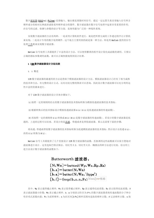
1 I IR数字滤波器设计方法比较1.1 概述IIR数字滤波器的最通用的方法是借助于模拟滤波器的设计方法。
模拟滤波器设计已经有了相当成熟的技术和方法,有完整的设计公式,还有比较完整的图表可以查询,因此设计数字滤波器可以充分利用这些丰富的资源来进行。
对于IIR数字滤波器的设计具体步骤如下:(1)按照一定的规则将给出的数字滤波器的技术指标转换为模拟低通滤波器的技术指标。
(2)根据转换后的技术指标设计模拟低通滤波器G(s)(G(s)是低通滤波器的传递函数)。
(3)再按照一定的规则将G(s)转换成H(z)(H(z)是数字滤波器的传递函数)。
若设计的数字滤波器是低通的,上述的过程可以结束,若设计的是高通、带通或者是带阻滤波器,那么还需要下面的步骤:将高通、带通或带阻数字滤波器的技术指标转换为低通模拟滤波器的技术指标,然后设计出低通G(s),再将G(s)转换为H(z)。
Matlab信号工具箱提供了几个直接设计IIR数字滤波器的函数,直接调用这些函数就可以很方便地对滤波器进行设计。
这里选取巴特沃斯法、切比雪夫I、切比雪夫Ⅱ、椭圆法四种方法进行比较。
给出用上述方法设计数字滤波器的函数如下:其中:Wp表示通带截止频率;Ws表示阻带截止频率;Rp表示通带纹波系数;Rs表示阻带纹波系数;N 表示滤波器最小阶数;Wn表示截止频率。
基于Matlab的IIR数字滤波器设计(论文)之欧阳光明创编
摘要欧阳光明(2021.03.07)在现代通信系统中,由于信号中经常混有各种复杂成分,所以很多信号分析都是基于滤波器而进行的,而数字滤波器是通过数值运算实现滤波,具有处理精度高、稳定、灵活、不存在阻抗匹配问题,可以实现模拟滤波器无法实现的特殊滤波功能。
数字滤波器根据其冲激响应函数的时域特性,可分为两种,即无限长冲激响应(IIR)数字滤波器和有限长冲激响应(FIR)数字滤波器。
实现IIR滤波器的阶次较低,所用的存储单元较少,效率高,精度高,而且能够保留一些模拟滤波器的优良特性,因此应用很广。
Matlab软件以矩阵运算为基础,把计算、可视化及程序设计有机融合到交互式工作环境中,并且为数字滤波的研究和应用提供了一个直观、高效、便捷的利器。
尤其是Matlab中的信号处理工具箱使各个领域的研究人员可以直观方便地进行科学研究与工程应用。
本文首先介绍了数字滤波器的概念,分类以及设计要求。
接着利用MATLAB函数语言编程,用信号处理图形界面FDATool来设计滤波器以及Sptool界面设计的方法,并用FDATool模拟IIR数字滤波器处理信号。
重点设计Chebyshev I型和Chebyshev II型数字低通滤波器,并介绍最优化设计。
【关键字】IIR滤波器FDAToolSptoolSimulinkABSTRACTIn modern communication systems,Because often mixed with various signal complex components,So many signal analysis is based on filters, and the digital filter is realized through numerical computation, digital filters filter with high precision, stability and flexibility, don'texist, can realize the impedance matching simulating the special filter cannot achieve filter function. Digital filter according to its impulse response function and characteristics of the time can be divided into two kinds, namely the infinite impulse response (IIR) digital filter and finite impulse response (FIR digital filters). The order of realizing IIR filter is used, low and high efficiency less storage unit, high precision, and can keep some simulation characteristics of filter, so it is widely used. Matlab software based on matrix computation, the calculation, visualization and program design of organic integration to interactiveenvironment for digital filter, and the research and application of provides an intuitive, efficient and convenient tool. Especially in the Matlab signal processing to all areas of research toolbox personnel can easily for scientific research and engineering application. This paper introduces the concept of digital filter, classification and design requirements. Then using MATLAB language programming, with functions of signal processing FDATool graphical interface design of interface design and Sptool filter, and FDATool analog signal processing IIR digital filter. Key design Chebyshev type I and II digital Chebyshev lowpass filter, and introduces optimization design.【Keywords】 IIR Filter FDATool Sptool Simulink目录前言1第一章数字滤波器2第一节数字滤波器的概念2第二节数字滤波器的分类2第三节数字滤波器的设计要求4第二章 IIR数字滤波器设计方法5第一节 IIR数字滤波器的设计步骤5第二节用脉冲相应不变法设计IIR数字滤波器6一、设计原理6二、脉冲响应不变法优缺点8第三节双线性变换法设计IIR数字滤波器9一、设计原理9二、双线性变换法优缺点11第三章 IIR滤波器的MATLAB设计13第一节 IIR数字滤波器的典型设计法14第二节 IIR数字滤波器的直接设计法18第三节 FDATool介绍和界面设计23第四节 FDATOOL设计IIR数字滤波器24第五节 SIMULINK 仿真IIR滤波器26总结29致谢30参考文献31结束语32前言随着信息时代和数字世界的到来,数字信号处理已成为当今一门极其重要的学科和技术领域。