SI8421中文资料
Si8461DB 数据手册说明书
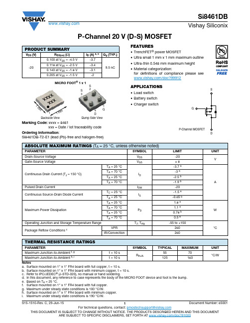
P-Channel 20 V (D-S) MOSFETMarking Code: xxxx = 8461xxx = Date / lot traceability code Ordering Information :Si8461DB-T2-E1 (lead (Pb)-free and halogen-free)FEATURES•TrenchFET ® power MOSFET•Ultra small 1 mm x 1 mm maximum outline •Ultra-thin 0.548 mm maximum height •Material categorization:for definitions of compliance please see /doc?99912APPLICATIONS•Load switch •Battery switch •Charger switchNotesa.Surface mounted on 1" x 1" FR4 board with full copper, t = 10 s.b.Surface mounted on 1" x 1" FR4 board with minimum copper, t = 10 s.c.Refer to IPC/JEDEC ® (J-STD-020), no manual or hand soldering.d.In this document, any reference to case represents the body of the MICRO FOOT device and foot is the bump.e.Based on T A = 25 °C.f.Surface mounted on 1" x 1" FR4 board with full copper.g.Maximum under steady state conditions is 100 °C/W.h.Surface mounted on 1" x 1" FR4 board with minimum copper.i.Maximum under steady state conditions is 190 °C/W.PRODUCT SUMMARYV DS (V)R DS(on) (Ω)I D (A) a, e Q g (TYP.)-200.100 at V GS = -4.5 V-3.79.5 nC0.118 at V GS = -2.5 V -3.40.140 at V GS = -1.8 V -3.10.205 at V GS = -1.5 V-2MICRO FOOT ® 1 x 1Bump S ide View1G4DS 3S 2Back s ide View11m m 1 mm x x x x xx x ABSOLUTE MAXIMUM RATINGS (T A = 25°C, unless otherwise noted)PA AMETE SYMBOL LIMIT UNITDrain-Source Voltage V DS -20VGate-Source VoltageV GS± 8Continuous Drain Current (T J = 150 °C)T A = 25 °CI D -3.7 a A T A = 70 °C -3 a T A = 25 °C -2.5 b T A = 70 °C-1.9 b Pulsed Drain CurrentI DM -20Continuous Source-Drain Diode CurrentT C = 25 °C I S -1.5 a T A = 25 °C -0.65 b Maximum Power DissipationT A = 25 °CP D 1.8 a W T A = 70 °C 1.1 a T A = 25 °C 0.78 b T A = 70 °C0.5 b Operating Junction and Storage Temperature Range T J , T stg -55 to +150°C Package Reflow Conditions cVPR 260IR/Convection260THERMAL RESISTANCE RATINGSPA AMETE SYMBOL TYPICAL MAXIMUM UNITMaximum Junction-to-Ambient f, g t = 10 s R thJA5570°C/WMaximum Junction-to-Ambient h, it = 10 s125160Notesa.Pulse test; pulse width ≤ 300 μs, duty cycle ≤ 2 %.b.Guaranteed by design, not subject to production testing.Stresses beyond those listed under “Absolute Maximum Ratings” may cause permanent damage to the device. These are stress ratings only, and functional operation of the device at these or any other conditions beyond those indicated in the operational sections of the specifications is not implied. Exposure to absolute maximum rating conditions for extended periods may affect device reliability.SPECIFICATIONS (T J = 25°C, unless otherwise noted)PA AMETE R SYMBOL TEST CONDITIONS MIN.TYP.MAX.UNITStaticDrain-Source Breakdown Voltage V DS V GS = 0 V, I D = -250 μA-20--V V DS Temperature Coefficient ΔV DS /T J I D = -250 μA --12-mV/°C V GS(th) Temperature Coefficient ΔV GS(th)/T J - 2.5-Gate-Source Threshold Voltage V GS(th) V DS = V GS , I D = -250 μA -0.4--1V Gate-Source LeakageI GSS V DS = 0 V, V GS = ± 8 V --± 100nA Zero Gate Voltage Drain Current I DSS V DS = -20 V, V GS = 0 V ---1μA V DS = -20 V, V GS = 0 V, T J = 70 °C---10On-State Drain Current aI D(on)V DS ≤ -5 V, V GS = -4.5 V -10--ADrain-Source On-State Resistance aR DS(on)V GS = -4.5 V, I D = -1.5 A-0.0830.100ΩV GS = -2.5 V, I D = -1.5 A -0.0980.118V GS = -1.8 V, I D = -1 A -0.1150.140V GS = -1.5 V, I D = -0.5 A-0.1360.205Forward Transconductance a g fsV DS = -10 V, I D = -1 A-7-S Dynamic bInput Capacitance C iss V DS = -10 V, V GS = 0 V, f = 1 MHz-610-pF Output CapacitanceC oss -120-Reverse Transfer Capacitance C rss -95-Total Gate Charge Q g V DS = -10 V, V GS = -8 V, ID = 1 A -1624nC V DS = -10 V, V GS = -4.5 V, I D = 1 A-9.515Gate-Source Charge Q gs -0.9-Gate-Drain Charge Q gd- 2.6-Gate Resistance R g V GS = -0.1 V, f = 1 MHz - 6.5-ΩTurn-On Delay Time t d(on)V DD = -10 V, R L = 10 ΩI D ≅ -1 A, V GEN = -4.5 V, R g = 1 Ω-1525ns Rise Timet r-2540Turn-Off Delay Time t d(off) -3555Fall Timet f -1015Turn-On Delay Time t d(on)V DD = -10 V, R L = 10 ΩI D ≅ -1 A, V GEN = -8 V, R g = 1 Ω-715Rise Timet r -1220Turn-Off Delay Time t d(off) -3250Fall Timet f -1220Drain-Source Body Diode Characteristics Continuous Source-Drain DiodeCurrentI S T A = 25 °C---1.5APulse Diode Forward Current I SM ---20Body Diode VoltageV SD I S = -1 A, V GS = 0 V--0.8-1.2V Body Diode Reverse Recovery Time t rr I F = -1 A, dI/dt = 100 A/μs, T J = 25 °C-1530ns Body Diode Reverse Recovery Charge Q rr -1020nC Reverse Recovery Fall Time t a -9-ns Reverse Recovery Rise Timet b-6-On-Resistance vs. Drain Current and Gate VoltageGate ChargeTransfer CharacteristicsCapacitanceOn-Resistance vs. Junction TemperatureTYPICAL CHARACTERISTICSThreshold VoltageSingle Pulse Power, Junction-to-Ambient Safe Operating Area, Junction-to-AmbientTYPICAL CHARACTERISTICS (25 °C, unless otherwise noted)Current Derating aPower DeratingNote•When mounted on 1" x 1" FR4 with full copper.Notea.The power dissipation P D is based on T J (max.) = 150 °C, using junction-to-case thermal resistance, and is more useful in settling the upper dissipation limit for cases where additional heatsinking is used. It is used to determine the current rating, when this rating falls below the package limit.TYPICAL CHARACTERISTICS (25 °C, unless otherwise noted)Normalized Thermal Transient Impedance, Junction-to-Ambient (1" x 1" FR4 Board with Full Copper)Vishay Silico nix maintains wo rldwide manufacturing capability. Pro ducts may be manufactured at o ne o f several qualified lo catio ns. Reliability data fo r Silico n Technology and Package Reliability represent a composite of all qualified locations. For related documents such as package/tape drawings, part marking, and reliability data, see /ppg?65001.Package InformationVishay SiliconixMICRO FOOT ®: 4-Bumps(1 mm x 1 mm, 0.5 mm Pitch, 0.286 mm Bump Height)Notes1.Bumps are 95.5/3.8/0.7 Sn/Ag/Cu.2.Backside surface is coated with a Ti/Ni/Ag layer.3.Non-solder mask defined copper landing pad.ser mark on the backside surface of die.5.“b1” is the diameter of the solderable substrate surface, defined by an opening in the solder resist layer solder mask defined.6.• is the location of pin 1Note•Use millimeters as the primary measurement.DIM. MILLIMETERSINCHES MIN. NOM.MAX. MIN. NOM.MAX. A 0.4580.5040.5500.01800.01980.0217A10.2140.2500.2860.00840.00980.0113A20.2440.2540.2640.00960.01000.0104b 0.2970.3300.3630.01170.01300.0143b10.2500.0098e 0.5000.0197s 0.2100.2300.2500.00830.00910.0096D 0.9200.960 1.0000.03620.03780.0394K0.0290.0650.1020.00110.00260.0040ECN: T15-0176-Rev. A, 27-Apr-15DWG: 6039Legal Disclaimer Notice VishayDisclaimerALL PRODUCT, PRODUCT SPECIFICAT IONS AND DAT A ARE SUBJECT T O CHANGE WIT HOUT NOT ICE T O IMPROVE RELIABILITY, FUNCTION OR DESIGN OR OTHERWISE.Vishay Intertechnology, Inc., its affiliates, agents, and employees, and all persons acting on its or their behalf (collectively, “Vishay”), disclaim any and all liability for any errors, inaccuracies or incompleteness contained in any datasheet or in any other disclosure relating to any product.Vishay makes no warranty, representation or guarantee regarding the suitability of the products for any particular purpose or the continuing production of any product. To the maximum extent permitted by applicable law, Vishay disclaims (i) any and all liability arising out of the application or use of any product, (ii) any and all liability, including without limitation special, consequential or incidental damages, and (iii) any and all implied warranties, including warranties of fitness for particular purpose, non-infringement and merchantability.Statements regarding the suitability of products for certain types of applications are based on Vishay’s knowledge of typical requirements that are often placed on Vishay products in generic applications. Such statements are not binding statements about the suitability of products for a particular application. It is the customer’s responsibility to validate that a particular product with the properties described in the product specification is suitable for use in a particular application. Parameters provided in datasheets and / or specifications may vary in different applications and performance may vary over time. All operating parameters, including typical parameters, must be validated for each customer application by the customer’s technical experts. Product specifications do not expand or otherwise modify Vishay’s terms and conditions of purchase, including but not limited to the warranty expressed therein.Except as expressly indicated in writing, Vishay products are not designed for use in medical, life-saving, or life-sustaining applications or for any other application in which the failure of the Vishay product could result in personal injury or death. Customers using or selling Vishay products not expressly indicated for use in such applications do so at their own risk. Please contact authorized Vishay personnel to obtain written terms and conditions regarding products designed for such applications.No license, express or implied, by estoppel or otherwise, to any intellectual property rights is granted by this document or by any conduct of Vishay. Product names and markings noted herein may be trademarks of their respective owners.© 2017 VISHAY INTERTECHNOLOGY, INC. ALL RIGHTS RESERVED。
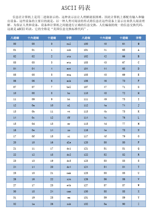
ASCII码表
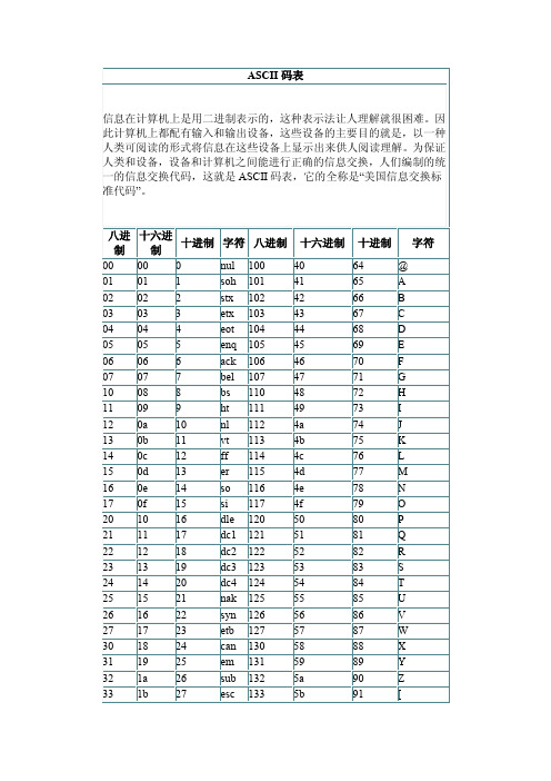
十六进制 40 41 42 43 44 45 46 47 48 49 4a 4b 4c 4d 4e 4f 50 51 52 53 54 55 5 66 67 68 69 70 71 72 73 74 75 76 77 78 79 80 81 82 83 84 85 86 87 88 89 90 91 @ A B C D E F G H I J K L M N O P Q R S T U V W X Y Z [
字符 八进制 nul soh stx etx eot enq ack bel bs ht nl vt ff er so si dle dc1 dc2 dc3 dc4 nak syn etb can em sub esc 100 101 102 103 104 105 106 107 110 111 112 113 114 115 116 117 120 121 122 123 124 125 126 127 130 131 132 133
92 93 94 95 96 97 98 99 100 101 102 103 104 105 106 107 108 109 110 111 112 113 114 115 116 117 118 119 120 121 122 123 124 125 126 127
\ ] ^ _ ' a b c d e f g h i j k l m n o p q r s t u v w x y z { | } ~ del
28 29 30 31 32 33 34 35 36 37 38 39 40 41 42 43 44 45 46 47 48 49 50 51 52 53 54 55 56 57 58 59 60 61 62 63
fs gs re us sp ! " # $ % & ` ( ) * + , . / 0 1 2 3 4 5 6 7 8 9 : ; < = > ?
SI8420-B-IS中文资料

Preliminary Rev. 0.1
3
元器件交易网
Si8410/20/21
1. Electrical Specifications
Table 1. Electrical Characteristics
(VDD1 = 5 V, VDD2 = 5 V, TA = –40 to 125 ºC)
—
7
10
Si8420-A,-B,-C, VDD2
All inputs 0 DC
—
4
7
Si8420-A,-B,-C, VDD1
All inputs 1 DC
—
11
15
Si8420-A,-B,-C, VDD2
All inputs 1 DC
—
4
6
Si8421-A,-B,-C, VDD1
All inputs 0 DC
>25 kV/µs DC correct No start-up initialization required <10 µs Startup Time High temperature operation
125 °C at 100 Mbps 100 °C at 150 Mbps Narrow body SOIC-8 package
元器件交易网
Si8410/20/21
2
Preliminary Rev. 0.1
元器件交易网
TABLE OF CONTENTS
Si8410/20/21
Section
Page
1. Electrical Specifications . . . . . . . . . . . . . . . . . . . . . . . . . . . . . . . . . . . . . . . . . . . . . . . . . . .4 2. Typical Performance Characteristics . . . . . . . . . . . . . . . . . . . . . . . . . . . . . . . . . . . . . . . . 17 3. Application Information . . . . . . . . . . . . . . . . . . . . . . . . . . . . . . . . . . . . . . . . . . . . . . . . . . . 19
AD8421_cn
One Technology Way, P.O. Box 9106, Norwood, MA 02062-9106, U.S.A. Tel: 781.329.4700 Fax: 781.461.3113 ©2012 Analog Devices, Inc. All rights reserved.
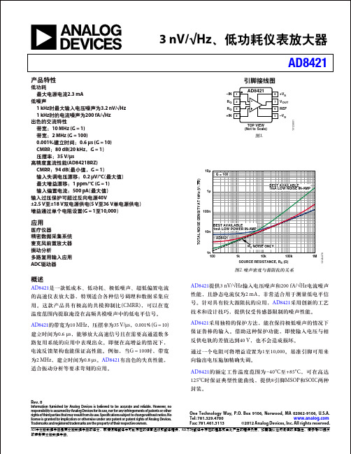
3 nV/√Hz、低功耗仪表放大器 AD8421
产品特性
低功耗 最大电源电流2.3 mA 低噪声 1 kHz时最大输入电压噪声为3.2 nV/√Hz 1 kHz时的电流噪声为200 fA/√Hz 出色的交流特性 带宽:10 MHz (G = 1) 带宽:2 MHz (G = 100) 0.001%建立时间:0.6 μs (G = 10) CMRR:80 dB(20 kHz,G = 1) 压摆率:35 V/μs 高精度直流性能(AD8421BRZ) CMRR:94 dB(最小值,G = 1) 输入失调电压漂移:0.2 µV/°C(最大值) 最大增益漂移:1 ppm/°C (G = 1) 输入偏置电流:500 pA(最大值) 输入过压保护可超过反向电源40V ±2.5 V至±18 V双电源供电(5 V至36 V单电源供电) 增益通过单个电阻设置(G = 1至10,000)
–IN RG RG +IN
1 2 3 4
引脚接线图
AD8421
8 7 6 5
+VS VOUT REF –VS
10123-001
TOP VIEW (Not to Scale)
图1.
10µ G = 100
TOTAL NOISE DENSITY AT 1kHz (V/√ Hz)
1µ
BEST AVAILABLE 7mA LOW NOISE IN-AMP
8421码原理
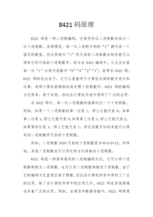
8421码原理8421码是一种二进制编码,它使用四位二进制数来表示一位十进制数。
其原理是,每一位二进制代码的“1”都代表一个固定的数值,然后将每位“1”所代表的二进制数加起来就可以得到它所代表的十进制数字。
因为在8421编码中,从左至右看每一位“1”分别代表数字“8”“4”“2”“1”,故得名8421码。
8421码的优点在于,它可以直接用于计算机内部的数字表示和运算,使得计算机能够轻松地处理十进制数字。
8421码的编码方式简单,易于实现,因此在计算机系统中得到了广泛的应用。
在8421码中,每一位二进制数的值都对应一个十进制数。
例如,如果一个二进制数的第一位是1,那么它就代表8;如果第二位是1,那么它就代表4;如果第三位是1,那么它就代表2;如果第四位是1,那么它就代表1。
将这些数字加起来就可以得到该二进制数所代表的十进制数。
例如,二进制数1010代表的十进制数是8+0+4+0=12。
同样地,其他二进制数也可以用这种方式转换成十进制数。
8421码是一种简单易用的二进制编码方式,它可以将十进制数转换为二进制数,也可以将二进制数转换回十进制数。
由于它的编码方式直观且易于理解,因此在计算机科学中得到了广泛的应用。
除了在计算机科学中的应用之外,8421码在其他领域也有着广泛的应用。
例如,在通信和数据传输中,8421码常常被用于数据编码和调制解调;在电子设备和系统中,8421码也常常被用于数字显示和键盘输入。
此外,8421码还有一些特殊的用途。
例如,在一些密码学中,8421码被用于加密和解密信息;在一些数学和逻辑领域中,8421码也被用于研究和设计算法和逻辑电路。
总之,8421码是一种非常有用的二进制编码方式,它不仅在计算机科学中有着广泛的应用,在其他领域中也发挥着重要的作用。
ASCII码表
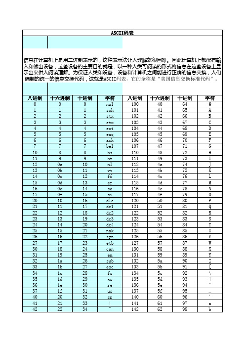
八进制 0 1 2 3 4 5 6 7 10 11 12 13 14 15 16 17 20 21 22 23 24 25 26 27 30 31 32 33 34 35 36 37 40 41 42
十六进制 0 1 2 3 4 5 6 7 8 9 0a 0b 0c 0d 0e 0f 10 11 12 13 14 15 16 17 18 19 1a 1b 1c 1d 1e 1f 20 21 22
43
23
35
44
24
36
45
25
37
46
26
38
47
27
39
50
28
40
51
29
41
52
2a
42
53
2b
43
54
2c
44
55
2d
45
56
2e
46
57
2f
47
60
30
48
61
31
49
62
32
50
63
33
51
64
34
52
65
35
53
66
36
54
67
37
55
70
38
56
71
39
57
72
3a
58
73
3b
59
~
?
177
7f
127
del
十进制 0 1 2 3 4 5 6 7 8 9 10 11 12 13 14 15 16 17 18 19 20 21 22 23 24 25 26 27 28 29 30 31 32 33 34
8421译码器20070830790
加法器的级连
S15 S14 S13 S12 C15 4 位加法器 C11 4 位加法器 S11 S10 S9 S8 C7 4 位加法器 S7 S6 S5 S4 C3 4 位加法器 S3 S2 S1 S0 C0-1
用与非门实现
Y A B AB
A B C & Y
4.1.2 组合逻辑电路的设计方法
电路功 能描述
穷 举 法
例:设计一个楼上、楼下开关的控制逻辑电路 来控制楼梯上的路灯,使之在上楼前,用楼下 开关打开电灯,上楼后,用楼上开关关灭电灯; 或者在下楼前,用楼上开关打开电灯,下楼后, 用楼下开关关灭电灯。 1 设楼上开关为A,楼下开关为B,灯泡为Y。并 设A、B闭合时为1,断开时为0;灯亮时Y为1, 灯灭时Y为0。根据逻辑要求列出真值表。
Ci m3 m5 Ai Bi Ai BiCi 1 Ai BiCi 1 Ai Bi ( Ai Bi Ai Bi )Ci 1 Ai B ( Ai Bi )Ci 1 Ai Bi
Ai Bi Ci -1 =1 =1 & & & (a) 逻辑图 Ci Ai Bi Ci -1 Ai Bi Ci -1 FA (b) 曾用符号 ∑
Si m1 m2 m4 m7 Ai BiCi 1 Ai BiCi 1 Ai BiCi 1 Ai BiCi 1 Ai ( BiCi 1 BiCi 1 ) Ai ( BiCi 1 BiCi 1 ) Ai ( Bi Ci 1 ) Ai ( Bi Ci 1 ) Ai Bi Ci 1
A 1 (a) A A Y1 (b) & Y1 A 1 (a) ≥1 Y2
Y1 AA 0
A A Y2
ascii码表
33 34 35 36 37 40 41 42 43 44 45 46 47 50 51 52 53 54 55 56 57 60 61 62 63 64 65 66 67 70 71 72 73
ASCII对照表
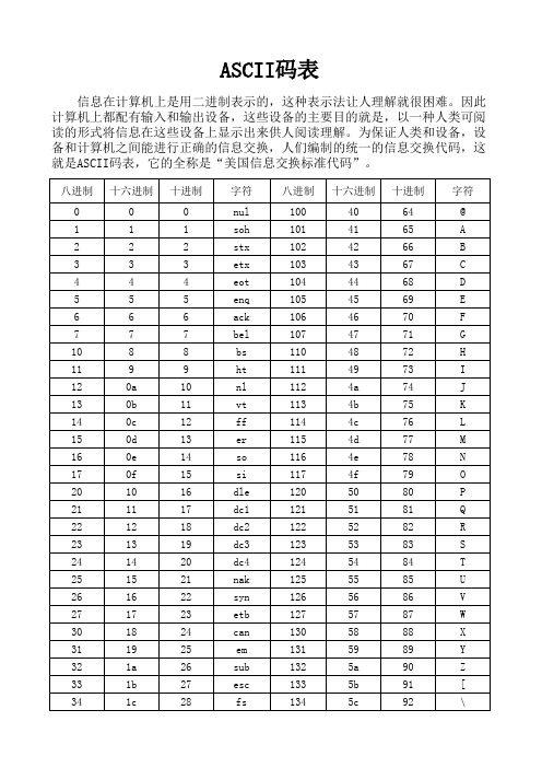
十进制 29 30 31 32 33 34 35 36 37 38 39 40 41 42 43 44 45 46 47 48 49 50 51 52 53 54 55 56 57 58 59 60 61 62 63
字符 gs re us sp ! " # $ % & ` ( ) * + , . / 0 1 2 3 4 5 6 7 8 9 : ; < = > ?
八进制 0 1 2 3 4 5 6 7 10 11 12 13 14 15 16 17 20 21 22 23 24 25 26 27 30 31 32 33 34 十六进制 0 1 2 3 4 5 6 7 8 9 0a 0b 0c 0d 0e 0f 10 11 12 13 14 15 16 17 18 19 1a 1b 1c 十进制 0 1 2 3 4 5 6 7 8 9 10 11 12 13 14 15 16 17 18 19 20 21 22 23 24 25 26 27 28 字符 nul soh stx etx eot enq ack bel bs ht nl vt ff er so si dle dc1 dc2 dc3 dc4 nak syn etb can em sub esc fs 八进制 100 101 102 103 104 105 106 107 110 111 112 113 114 115 116 117 120 121 122 123 124 125 126 127 130 131 132 133 134 十六进制 40 41 42 43 44 45 46 47 48 49 4a 4b 4c 4d 4e 4f 50 51 52 53 54 55 56 57 58 59 5a 5b 5c 十进制 64 65 66 67 68 69 70 71 72 73 74 75 76 77 78 79 80 81 82 83 84 85 86 87 88 89 90 91 92 字符 @ A B C D E F G H I J K L M N O P Q R S T U V W X Y Z [ \
前苏联二极管参数表
前苏联二极管参数表前苏联二极管参数表1. 引言二极管是一种电子组件,具有非常重要的应用价值。
在过去的几十年里,前苏联产生了大量的二极管,这些二极管参数表记录了其性能特点、规格和用途等信息。
本文将深入探讨这些前苏联二极管参数表的内容和意义。
2. 背景在过去的几十年里,前苏联是一个相当重要的电子器件制造国家。
他们生产了大量的二极管,这些二极管在军事、航天、通信等领域发挥了重要作用。
前苏联的二极管参数表对于了解这些器件的性能特点至关重要。
3. 前苏联二极管参数表的内容前苏联二极管参数表包含了许多不同类型的二极管的参数信息。
其中包括但不限于:正向电流、反向电压、导通压降、最大功率、最大反向电流和封装类型等。
这些参数可以帮助我们了解二极管的工作条件和限制。
4. 前苏联二极管参数表的意义前苏联二极管参数表的意义在于提供了有关这些二极管性能特点的信息。
通过研究和分析这些参数,我们可以了解二极管的使用条件和限制,从而更好地应用和设计电子电路。
5. 个人观点和理解在我看来,前苏联二极管参数表是非常珍贵和有价值的。
这些参数表记录了前苏联在二极管领域的成就和贡献,也展示了他们在科学研究和技术开发方面的实力。
通过研究这些参数表,我们可以深入探讨前苏联的科技发展历程,了解他们在二极管技术方面的突破和创新。
6. 总结和回顾前苏联二极管参数表是对前苏联二极管性能特点的记录和总结。
通过深入分析这些参数表,我们可以全面、深刻和灵活地理解前苏联二极管的特点和性能限制。
这些参数表对于研究电子电路设计、科技历史以及前苏联的科技发展都具有重要价值。
7. 结束语本文深入探讨了前苏联二极管参数表的内容和意义。
通过研究这些参数表,我们可以更好地了解前苏联二极管的性能特点和限制,从而为电子电路设计和科技研究提供有价值的参考信息。
希望这篇文章能够增加大家对于前苏联二极管参数表的认识和理解。
在撰写这篇文章的过程中,我对前苏联二极管参数表产生了浓厚的兴趣。
PMC常用BCD码说明
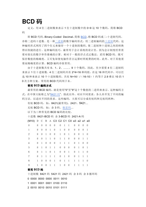
BCD码定义:用4位二进制数来表示1位十进制数中的0~9这10个数码,简称BCD 码即BCD代码。
Binary-Coded Decimal,简称BCD,称BCD码或二-十进制代码,亦称二进码十进数。
是一种二进制的数字编码形式,用二进制编码的十进制代码。
这种编码形式利用了四个位元来储存一个十进制的数码,使二进制和十进制之间的转换得以快捷的进行。
这种编码技巧,最常用于会计系统的设计里,因为会计制度经常需要对很长的数字串作准确的计算。
相对于一般的浮点式记数法,采用BCD码,既可保存数值的精确度,又可免却使电脑作浮点运算时所耗费的时间。
此外,对于其他需要高精确度的计算,BCD编码亦很常用。
由于十进制数共有0、1、2、……、9十个数码,因此,至少需要4位二进制码来表示1位十进制数。
4位二进制码共有2^4=16种码组,在这16种代码中,可以任选10种来表示10个十进制数码,共有N=16!/(16-10)!约等于2.9乘以10的1 0次方种方案。
常用的BCD代码列于末。
常用BCD编码方式最常用的BCD编码,就是使用"0"至"9"这十个数值的二进码来表示。
这种编码方式,在中国大陆称之为“8421码”。
除此以外,对应不同需求,各人亦开发了不同的编码方法,以适应不同的需求。
这些编码,大致可以分成有权码和无权码两种:有权BCD码,如:8421(最常用)、2421、5421…无权BCD码,如:余3码、格雷码…以下为三种常见的BCD编码的比较。
十进数8421-BCD码余3-BCD码2421-A码(M10) DCBAC3 C2 C1 C0 a3 a2 a1 a00000000110000100010100000120010010100103001101100011401000111010050101100001016011010010110701111010011181000101111109100111001111常用BCD码十进制数8421码5421码2421码余3码余3循环码0 0000 0000 0000 0011 00101 0001 0001 0001 0100 01102 0010 0010 0010 0101 01113 0011 0011 0011 0110 01014 0100 0100 0100 0111 01005 0101 1000 1011 1000 11006 0110 1001 1100 1001 11017 0111 1010 1101 1010 11118 1000 1011 1110 1011 11109 1001 1100 1111 1100 1010-----------------------特点:8421编码直观,好理解。
8421资料
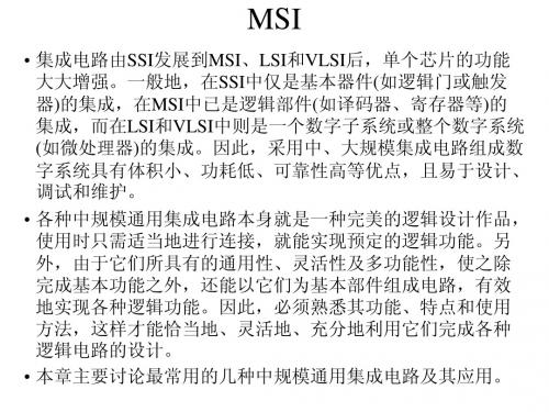
译码器Ⅱ
•右图分别是T4138型3-8线 译码器的逻辑电路图。图 中,A2、A1、A0为输入 端;Y0’、Y1’、Y2’、 Y3’、Y4’、Y5’、Y6’和 Y7’为输出端;S1、S2’、 S3’为使能端,它的作用 是禁止或选通译码器。该 译码器真值表如下表。由 真值表可知,当S1=1, S2’+S3’=0时,无论A2、 A1,和A0取何值,输出 Y0’、…、Y7’中有且仅 有一个为0(低电平有效), 其余都是l。
二进制并行加法器Ⅰ
•串行进位二进制并行加法器是由全 加器级联而成的。其特点是:被加 数和加数的各位能同时并行到达各 位的输入端,而各位全加器的进位 输入则是按照由低位向高位逐级串 行传递的,各进位形成一个进位链。 由于每一位相加的和都与本位进位 输入有关,所以,最高位必须等到 各低位全部相加完成并送来进位信 号之后才能产生运算结果。显然, 这种加法器运算速度较慢,而且位 数越多,速度就越低。
0 0 0 0 0 0 0 0 d 1
译码器Ⅳ
•二-十进制译码器的功能是将4位BCD码的10组代码翻译成10个 十进制数字符号对应的输出信号。下图所示为MSI二-十进制 译码器T331的逻辑电路图。 T331是一个将8421码转换成十进 制数字的译码器,其输入A3~A0为8421码,输出Y0’~Y9’分 别代表十进制数字0-9。该译码器的真值表如下表所示。 •从真值表可知,该译 码器的输出为低电平有 效。其次,对于8421码 中不允许出现的6个非 法码(1010-1111),译码 器输出端Y0~Y9均无 低电平信号产生,即译 码器对这6个非法码拒 绝翻译。这种译码器的 优点是当输入端出现非 法码时,电路不会产生 错误译码。
二进制并行加法器Ⅶ
• 其中,片Ⅰ用来对两个1位十进制数的余3码进行相加,片Ⅱ 用来对相加结果进行修正。修正控制函数为片Ⅰ的进位输出 FC4,当FC4=0时,将片Ⅰ的和输出送至片Ⅱ,并将其加上 二进制数1101(即采用补码实现运算结果减二进制数0011); 当FC4=1时,将片Ⅰ的和输出送至片Ⅱ,并将其加上二进制 数0011,片Ⅱ的和输出即为两余3码相加的和数。 • 例7.4 用4位二进制并行加法器实现4位二进制数乘法器的 逻辑功能。 • 解 设两个无符号4位二进制数X和Y,X=x3x2x1x0, Y=y3y2yly0,则X和Y的乘积Z为一个8位二进制数,可令 Z=Z7Z6Z5Z4Z3Z2ZlZ0。两数相乘求积的过程如下:因为两 个1位二进制数相乘的法则和逻辑“与”运算法则相同,所 以“积”项xiyi(i,j=0,1,2,3)可用两输入与门实现。而 对部分积求和则可用并行加法器实现。由此可知,实现4位 二进制数乘法运算的逻辑电路可由16个两输入与门和3个4位 二进制并行加法器构成。逻辑电路图如下图。
ASCII码对照表

好用的ASCII 码对照表完整版信息在计算机上是用二进制表示的,这种表示法让人理解就很困难。
因此计算机上都配有输入和输出设备,这些设备的主要目的就是,以一种人类可阅读的形式将信息在这些设备上显示出来供人阅读理解。
为保证人类和设备,设备和计算机之间能进行正确的信息交换,人们编制的统一的信息交换代码,这就是ASCII 码表,它的全称是“美国信息交换标准代码ASCII 码对照表在Web开发时,如下的ASCII 码只要加上&#和; 就可以变成Web可以辨认的字符了在处理特殊字符的时候特别有用,如:' 单引号在数据库查询的时候是杀手,但是如果转换成'(注意:转换后的机构有:&# +字符的ASCII码值+; 三个部分组成)再来存数据库,就没有什么影响了。
其他的字符与ASCII 码的对照如下表键盘常用ASCII 码ESC键VK_ESCAPE (27) 回车键:VK_RETURN (13) TAB键:VK_TAB (9) Caps Lock 键:VK_CAPITAL (20) Shift 键:VK_SHIFT ($10) Ctrl 键:VK_CONTROL (17) Alt 键:VK_MENU (18) 空格键:VK_SPACE ($20/32) 退格键:VK_BACK (8) 左徽标键:VK_LWIN (91) 右徽标键:VK_LWIN (92) 鼠标右键快捷键:VK_APPS (93)Insert 键:VK_INSERT (45) Home键:VK_HOME (36)Page Up:VK_PRIOR (33) PageDown:VK_NEXT (34) End键:VK_END (35)Delete 键:VK_DELETE (46) 方向键(←):VK_LEFT (37) 方向键(↑):VK_UP(38) 方向键(→):VK_RIGHT (39) 方向键(↓):VK_DOWN (40)F1键:VK_F1 (112)F2键:VK_F2 (113)F3键:VK_F3 (114)F4键:VK_F4 (115)F5键:VK_F5 (116)F6键:VK_F6 (117)F7键:VK_F7 (118)F8键:VK_F8 (119)F9键:VK_F9 (120)F10键:VK_F10 (121)F11键:VK_F11 (122)F12键:VK_F12 (123)Num Lock 键:VK_NUMLOCK (144) 小键盘0:VK_NUMPAD0 (96)小键盘1:VK_NUMPAD0 (97) 小键盘2:VK_NUMPAD0 (98) 小键盘3:VK_NUMPAD0(99) 小键盘4:VK_NUMPAD0 (100) 小键盘5:VK_NUMPAD0 (101) 小键盘6:VK_NUMPAD0 (102) 小键盘7:VK_NUMPAD0 (103) 小键盘8:VK_NUMPAD0 (104) 小键盘9:VK_NUMPAD0 (105) 小键盘.:VK_DECIMAL (110) 小键盘*:VK_MULTIPLY (106) 小键盘+:VK_MULTIPLY (107) 小键盘-:VK_SUBTRACT (109) 小键盘/:VK_DIVIDE (111)Pause Break 键:VK_PAUSE (19)Scroll Lock 键:VK_SCROLL (145)enjoy the trust of 得到...的信任have / put trust in 信任in trust 受托的,代为保管的take ...on trust 对...不加考察信以为真trust on 信赖give a new turn to 对~~ 予以新的看法turn around / round 转身,转过来,改变意见turn back 折回,往回走turn ⋯away 赶走⋯⋯,辞退⋯⋯,把⋯⋯打发走,转脸不睬,使转变方向turn to ⋯转向⋯⋯,( for help )向⋯⋯求助,查阅,变成;着手于think through ⋯思考⋯⋯直到得出结论,想通think of 想到,想起,认为,对⋯⋯有看法/ 想法。
ASCII码表
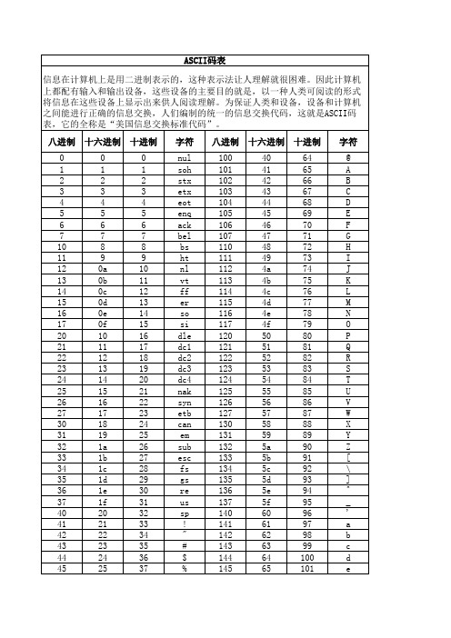
66 67 68 69 6a 6b 6c 6d 6e 6f 70 71 72 73 74 75 76 77 78 79 7a 7b 7c 7d 7e 7f
102 103 104 105 106 107 108 109 110 111 112 113 114 115 116 117 118 119 120 121 122 123 124 125 126 127
ASCII码表 信息在计算机上是用二进制表示的,这种表示法让人理解就很困难。因此计算机 上都配有输入和输出设备,这些设备的主要目的就是,以一种人类可阅读的形式 将信息在这些设备上显示出来供人阅读理解。为保证人类和设备,设备和计算机 之间能进行正确的信息交换,人们编制的统一的信息交换代码,这就是ASCII码 表,它的全称是“美国信息交换标准代码”。 八进制 十六进制 十进制 0 1 2 3 4 5 6 7 10 11 12 13 14 15 16 17 20 21 22 23 24 25 26 27 30 31 32 33 34 35 36 37 40 41 42 43 44 45 0 1 2 3 4 5 6 7 8 9 0a 0b 0c 0d 0e 0f 10 11 12 13 14 15 16 17 18 19 1a 1b 1c 1d 1e 1f 20 21 22 23 24 25 0 1 2 3 4 5 6 7 8 9 10 11 12 13 14 15 16 17 18 19 20 21 22 23 24 25 26 27 28 29 30 31 32 33 34 35 36 37 字符 nul soh stx etx eot enq ack bel bs ht nl vt ff er so si dle dc1 dc2 dc3 dc4 nak syn etb can em sub esc fs gs re us sp ! " # $ % 八进制 十六进制 十进制 100 101 102 103 104 105 106 107 110 111 112 113 114 115 116 117 120 121 122 123 124 125 126 127 130 131 132 133 134 135 136 137 140 141 142 143 144 145 40 41 42 43 44 45 46 47 48 49 4a 4b 4c 4d 4e 4f 50 51 52 53 54 55 56 57 58 59 5a 5b 5c 5d 5e 5f 60 61 62 63 64 65 64 65 66 67 68 69 70 71 72 73 74 75 76 77 78 79 80 81 82 83 84 85 86 87 88 89 90 91 92 93 94 95 96 97 98 99 100 101 字符 @ A B C D E F G H I J K L M N O P Q R S T U V W X Y Z [ \ ] ^ _ ' a b c d e
Si8410 20 21和Si8422 23型号的Silicon Labs低功耗数字隔离器数据手册说
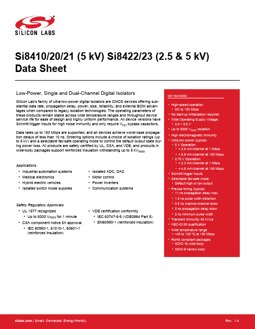
Si8410/20/21 (5 kV) Si8422/23 (2.5 & 5 kV) Data SheetLow-Power, Single and Dual-Channel Digital IsolatorsSilicon Lab's family of ultra-low-power digital isolators are CMOS devices offering sub-stantial data rate, propagation delay, power, size, reliability, and external BOM advan-tages when compared to legacy isolation technologies. The operating parameters ofthese products remain stable across wide temperature ranges and throughout deviceservice life for ease of design and highly uniform performance. All device versions haveSchmitt trigger inputs for high noise immunity and only require V DD bypass capacitors.Data rates up to 150 Mbps are supported, and all devices achieve worst-case propaga-tion delays of less than 10 ns. Ordering options include a choice of isolation ratings (upto 5 kV) and a selectable fail-safe operating mode to control the default output state dur-ing power loss. All products are safety certified by UL, CSA, and VDE, and products inwide-body packages support reinforced insulation withstanding up to 5 kV RMS.Applications•Industrial automation systems •Medical electronics•Hybrid electric vehicles •Isolated switch mode supplies •Isolated ADC, DAC •Motor control•Power inverters •Communication systemsSafety Regulatory Approvals•UL 1577 recognized•Up to 5000 V RMS for 1 minute •CSA component notice 5A approval •IEC 60950-1, 61010-1, 60601-1(reinforced insulation)•VDE certification conformity•IEC 60747-5-5 (VDE0884 Part 5)•EN60950-1 (reinforced insulation)1. Features List•High-speed operation•DC to 150 Mbps•No start-up initialization required •Wide Operating Supply Voltage:• 2.6 – 5.5 V•Up to 5000 V RMS isolation•High electromagnetic immunity •Ultra low power (typical)• 5 V Operation:•< 2.6 mA/channel at 1 Mbps•< 6.8 mA/channel at 100 Mbps • 2.70 V Operation:•< 2.3 mA/channel at 1 Mbps•< 4.6 mA/channel at 100 Mbps •Schmitt trigger inputs •Selectable fail-safe mode•Default high or low output •Precise timing (typical)•11 ns propagation delay max • 1.5 ns pulse width distortion•0.5 ns channel-channel skew • 2 ns propagation delay skew• 5 ns minimum pulse width •Transient immunity 45 kV/µs •AEC-Q100 qualification •Wide temperature range•–40 to 125 °C at 150 Mbps •RoHS compliant packages•SOIC-16 wide body•SOIC-8 narrow body2. Ordering GuideTable 2.1. Ordering Guide1,2,33. Functional Description3.1 Theory of OperationThe operation of an Si84xx channel is analogous to that of an opto coupler, except an RF carrier is modulated instead of light. This simple architecture provides a robust isolated data path and requires no special considerations or initialization at start-up. A simplified block diagram for a single Si84xx channel is shown in the figure below.A BFigure 3.1. Simplified Channel DiagramA channel consists of an RF Transmitter and RF Receiver separated by a semiconductor-based isolation barrier. Referring to the Transmitter, input A modulates the carrier provided by an RF oscillator using on/off keying. The Receiver contains a demodulator that decodes the input state according to its RF energy content and applies the result to outputB via the output driver. This RF on/off keying scheme is superior to pulse code schemes as it provides best-in-class noise immunity, low power consumption, and better immunity to magnetic fields. See the figure below for more details.Input SignalModulation SignalOutput SignalFigure 3.2. Modulation Scheme3.2 Eye DiagramThe figure below illustrates an eye-diagram taken on an Si8422. For the data source, the test used an Anritsu (MP1763C) Pulse Pattern Generator set to 1000 ns/div. The output of the generator's clock and data from an Si8422 were captured on an oscilloscope. The re-sults illustrate that data integrity was maintained even at the high data rate of 150 Mbps. The results also show that 2 ns pulse width distortion and 350 ps peak jitter were exhibited.Figure 3.3. Eye Diagram4. Device OperationDevice behavior during start-up, normal operation, and shutdown is shown in Figure 4.1 Device Behavior during Normal Operation on page 6, where UVLO+ and UVLO- are the positive-going and negative-going thresholds respectively. Refer to the table below to determine outputs when power supply (V DD) is not present.Table 4.1. Si84xx Logic Operation Table4.1 Device StartupOutputs are held low during powerup until V DD is above the UVLO threshold for time period tSTART. Following this, the outputs follow the states of inputs.4.2 Under Voltage LockoutUnder Voltage Lockout (UVLO) is provided to prevent erroneous operation during device startup and shutdown or when V DD is below its specified operating circuits range. Both Side A and Side B each have their own undervoltage lockout monitors. Each side can enter or exit UVLO independently. For example, Side A unconditionally enters UVLO when V DD1 falls below V DD1(UVLO–) and exits UVLO when V DD1 rises above V DD1(UVLO+). Side B operates the same as Side A with respect to its V DD2 supply.VVFigure 4.1. Device Behavior during Normal Operation4.3 Layout RecommendationsTo ensure safety in the end user application, high voltage circuits (i.e., circuits with >30 V AC) must be physically separated from the safety extra-low voltage circuits (SELV is a circuit with <30 V AC) by a certain distance (creepage/clearance). If a component, such as a digital isolator, straddles this isolation barrier, it must meet those creepage/clearance requirements and also provide a sufficiently large high-voltage breakdown protection rating (commonly referred to as working voltage protection). Table 5.5 Regulatory Information1 on page 20and Table 5.6 Insulation and Safety-Related Specifications on page 21detail the working voltage and creepage/clearance capabilities of the Si84xx. These tables also detail the component standards (UL1577, IEC60747, CSA 5A), which are readily accepted by certification bodies to provide proof for end-system specifications requirements. Refer to the end-system specification (61010-1, 60950-1, 60601-1, etc.) requirements before starting any design that uses a digital isolator.4.3.1 Supply BypassThe Si841x/2x family requires a 0.1 μF bypass capacitor between V DD1and GND1 and V DD2and GND2. The capacitor should be placed as close as possible to the package. To enhance the robustness of a design, it is further recommended that the user also add 1μF bypass capacitors and include 100 Ω resistors in series with the inputs and outputs if the system is excessively noisy.4.3.2 Pin ConnectionsNo connect pins are not internally connected. They can be left floating, tied to V DD, or tied to GND.4.3.3 Output Pin TerminationThe nominal output impedance of an isolator driver channel is approximately 50 Ω, ±40%, which is a combination of the value of the on-chip series termination resistor and channel resistance of the output driver FET. When driving loads where transmission line effects will be a factor, output pins should be appropriately terminated with controlled impedance PCB traces.4.4 Fail-Safe Operating ModeSi84xx devices feature a selectable (by ordering option) mode whereby the default output state (when the input supply is unpowered) can either be a logic high or logic low when the output supply is powered. See Table 4.1 Si84xx Logic Operation Table on page 5 and Section 2. Ordering Guide for more information.4.5 Typical Performance CharacteristicsThe typical performance characteristics depicted in the following diagrams are for information purposes only. Refer to Table 5.2 Electri-cal Characteristics on page 9 through Table 5.4 Electrical Characteristics 1 on page 17for actual specification limits.Figure 4.2. Si8410 Typical V DD1 Supply Currentvs. Data Rate 5, 3.3, and 2.70 V Operation Figure 4.3. Si8420 Typical V DD1 Supply Currentvs. Data Rate 5, 3.3, and 2.70 V OperationFigure 4.4. Si8421 Typical V DD1 or V DD2 Supply Current vs.Data Rate 5, 3.3, and 2.70 V Operation (15 pF Load)Figure 4.5. Si8410 Typical V DD2 Supply Current vs. Data Rate 5, 3.3, and 2.70 V Operation(15 pF Load)Figure 4.6. Si8420 Typical V DD2 Supply Current vs. Data Rate5, 3.3, and 2.70 V Operation(15 pF Load)Figure 4.7. Si8422 Typical V DD1 or V DD2 Supply Current vs.Data Rate 5, 3.3, and 2.70 V Operation (15 pF Load)Figure 4.8. Si8423 Typical V DD1 Supply Currentvs. Data Rate 5, 3.3, and 2.70 V OperationFigure 4.9. Si8423 Typical V DD2 Supply Current vs. Data Rate5, 3.3, and 2.70 V Operation(15 pF Load)Figure 4.10. Propagation Delayvs. TemperatureElectrical Specifications 5. Electrical SpecificationsTable 5.1. Recommended Operating ConditionsTable 5.2. Electrical Characteristics(V DD1 = 5 V ±10%, V DD2 = 5 V ±10%, T A = –40 to 125 °C)InputTypical OutputFigure 5.1. Propagation Delay TimingTable 5.3. Electrical Characteristics (V DD1 = 3.3 V ±10%, V DD2 = 3.3 V ±10%, T A = –40 to 125 °C)Table 5.4. Electrical Characteristics1 (V DD1 = 2.70 V, V DD2 = 2.70 V, T A = –40 to 125 °C)Table 5.5. Regulatory Information1CSAThe Si84xx is certified under CSA Component Acceptance Notice 5A. For more details, see File 232873.61010-1: Up to 600 V RMS reinforced insulation working voltage; up to 600 V RMS basic insulation working voltage.60950-1: Up to 600 V RMS reinforced insulation working voltage; up to 1000 V RMS basic insulation working voltage.60601-1: Up to 125 V RMS reinforced insulation working voltage; up to 380 V RMS basic insulation working voltage.VDEThe Si84xx is certified according to IEC 60747-5-5. For more details, see File 5006301-4880-0001.60747-5-5: Up to 891 V peak for basic insulation working voltage.60950-1: Up to 600 V RMS reinforced insulation working voltage; up to 1000 V RMS basic insulation working voltage.ULThe Si84xx is certified under UL1577 component recognition program. For more details, see File E257455.Rated up to 5000 V RMS isolation voltage for basic insulation.Note:1.Regulatory Certifications apply to2.5 kV RMS rated devices which are production tested to3.0 kV RMS for 1 sec. Regulatory Certifi-cations apply to 5.0 kV RMS rated devices which are production tested to 6.0 kV RMS for 1 sec.For more information, see Section 2. Ordering Guide.Table 5.6. Insulation and Safety-Related SpecificationsTable 5.7. IEC 60747-5-5 Insulation Characteristics for Si84xxxx1Table 5.8. IEC Safety Limiting Values1Table 5.9. Thermal Characteristics200150********2501250Case Temperature (ºC)S a f e t y -L i m i t i n g V a l u es (m A )375Figure 5.2. (WB SOIC-16) Thermal Derating Curve, Dependence of Safety Limiting Valueswith Case Temperature per DIN EN 60747-5-5200150********2001000Case Temperature (ºC)S a f e t y -L i m i t i n g V a l u es (m A )300Figure 5.3. (NB SOIC-8) Thermal Derating Curve, Dependence of Safety Limiting Valueswith Case Temperature per DIN EN 60747-5-5Table 5.10. Absolute Maximum Ratings16. Pin Descriptions6.1 Pin Descriptions (Wide-Body SOIC)VVVVFigure 6.1. Wide-Body SOICTable 6.1. Pin Descriptions6.2 Pin Descriptions (Narrow-Body SOIC)V DD2V DD2Figure 6.2. Narrow-Body SOIC7. Package Outlines7.1 Package Outline (16-Pin Wide Body SOIC)The figure below illustrates the package details for the Si84xx Digital Isolator. The table below lists the values for the dimensions shown in the illustration.Figure 7.1. 16-Pin Wide Body SOICTable 7.1. Package Diagram Dimensions7.2 Package Outline (8-Pin Narrow Body SOIC)The figure below illustrates the package details for the Si84xx. The table below lists the values for the dimensions shown in the illustra-tion.Figure 7.2. 8-pin Small Outline Integrated Circuit (SOIC) PackageTable 7.2. Package Diagram Dimensions8. Land Patterns8.1 Land Pattern (16-Pin Wide-Body SOIC)The figure below illustrates the recommended land pattern details for the Si84xx in a 16-pin wide-body SOIC. The table below lists the values for the dimensions shown in the illustration.Figure 8.1. 16-Pin SOIC Land PatternTable 8.1. 16-Pin Wide Body SOIC Land Pattern Dimensions8.2 Land Pattern (8-Pin Narrow Body SOIC)The figure below illustrates the recommended land pattern details for the Si84xx in an 8-pin narrow-body SOIC. The table below lists the values for the dimensions shown in the illustration.Figure 8.2. PCB Land Pattern: 8-Pin Narrow Body SOICTable 8.2. PCM Land Pattern Dimensions (8-Pin Narrow Body SOIC)9. Top Markings9.1 Top Marking (16-Pin Wide Body SOIC)Figure 9.1. Isolator Top MarkingTable 9.1. Top Marking ExplanationLine 1 Marking:Base Part NumberOrdering Options(See 2. Ordering Guide for more information).Si84 = Isolator product seriesXY = Channel ConfigurationX = # of data channels (2, 1)Y = # of reverse channels (1, 0)1,2S = Speed GradeA = 1 MbpsB = 150 MbpsV = Insulation ratingA = 1 kV;B = 2.5 kV;C = 3.75 kV;D = 5 kVLine 2 Marking:YY = YearWW = Workweek Assigned by assembly subcontractor. Corresponds to the year and workweek of the mold date.TTTTTT = Mfg Code Manufacturing code from assembly house. Line 3 Marking:Circle = 1.7 mm Diameter(Center-Justified)“e4” Pb-Free Symbol.Country of Origin ISO Code Abbreviation TW = Taiwan.Notes:1.The Si8422 has one reverse channel.2.The Si8423 has zero reverse channels.9.2 Top Marking (8-Pin Narrow-Body SOIC)Figure 9.2. Isolator Top MarkingTable 9.2. Top Marking ExplanationLine 1 Marking:Base Part NumberOrdering Options(See 2. Ordering Guide for more information).Si84 = Isolator product seriesXY = Channel ConfigurationX = # of data channels (2, 1)Y = # of reverse channels (1, 0)1,2S = Speed GradeA = 1 MbpsB = 150 MbpsV = Insulation ratingA = 1 kV;B = 2.5 kV;C = 3.75 kV;D = 5 kVLine 2 Marking:YY = YearWW = Workweek Assigned by assembly subcontractor. Corresponds to the year and workweek of the mold date.R = Product (OPN) Revision F = Wafer FabLine 3 Marking:Circle = 1.1 mm DiameterLeft-Justified “e3” Pb-Free Symbol.First two characters of the manufacturing code.A = Assembly SiteI = Internal CodeXX = Serial Lot NumberLast four characters of the manufacturing code.Notes:1.The Si8422 has one reverse channel.2.The Si8423 has zero reverse channels.Document Change List 10. Document Change List10.1 Revision 0.1•Initial release.10.2 Revision 0.1 to Revision 1.0•Updated features list.•Updated transient immunity.•Removed block diagram from front page.•Added chip graphics on front page.•Added Peak Eye Diagram jitter in Table 5.2 Electrical Characteristics on page 9through Table 5.4 Electrical Characteristics1on page 17.•Updated transient immunity•Moved Table 4.1 Si84xx Logic Operation Table on page 5 to Section 4. Device Operation.•Added Section 4. Device Operation.•Added Section 4.4 Fail-Safe Operating Mode.•Moved Section 4.5 Typical Performance Characteristics.•Deleted RF Radiated Emissions section.•Deleted RF Magnetic and Common-Mode Transient Immunity section.•Updated MSL rating to MSL2A.10.3 Revision 1.0 to Revision 1.1•Numerous text edits.•Added table notes to Table 9.1 Top Marking Explanation on page 32 and Table 9.2 Top Marking Explanation on page 33.10.4 Revision 1.1 to Revision 1.2•Updated Timing Characteristics in Table 5.2 Electrical Characteristics on page 9through Table 5.4 Electrical Characteristics1on page 17.10.5 Revision 1.2 to Revision 1.3•Added references to AEC-Q100 qualified throughout.•Changed all 60747-5-2 references to 60747-5-5.•Updated Table 2.1 Ordering Guide1,2,3 on page 2.•Added table notes 1 and 2.•Removed references to moisture sensitivity levels.•Added Revision D ordering information.•Removed older revisions.•Updated Section 9.1 Top Marking (16-Pin Wide Body SOIC).10.6 Revision 1.3 to Revision 1.4September 16, 2016•Updated data sheet format.Table of Contents1. Features List (1)2. Ordering Guide (2)3. Functional Description (3)3.1 Theory of Operation (3)3.2 Eye Diagram (4)4. Device Operation (5)4.1 Device Startup (5)4.2 Under Voltage Lockout (6)4.3 Layout Recommendations (6)4.3.1 Supply Bypass (6)4.3.2 Pin Connections (6)4.3.3 Output Pin Termination (6)4.4 Fail-Safe Operating Mode (6)4.5 Typical Performance Characteristics (7)5. Electrical Specifications (9)6. Pin Descriptions (25)6.1 Pin Descriptions (Wide-Body SOIC) (25)6.2 Pin Descriptions (Narrow-Body SOIC) (26)7. Package Outlines (27)7.1 Package Outline (16-Pin Wide Body SOIC) (27)7.2 Package Outline (8-Pin Narrow Body SOIC) (28)8. Land Patterns (30)8.1 Land Pattern (16-Pin Wide-Body SOIC) (30)8.2 Land Pattern (8-Pin Narrow Body SOIC) (31)9. Top Markings (32)9.1 Top Marking (16-Pin Wide Body SOIC) (32)9.2 Top Marking (8-Pin Narrow-Body SOIC) (33)10. Document Change List (34)10.1 Revision 0.1 (34)10.2 Revision 0.1 to Revision 1.0 (34)10.3 Revision 1.0 to Revision 1.1 (34)10.4 Revision 1.1 to Revision 1.2 (34)10.5 Revision 1.2 to Revision 1.3 (34)10.6 Revision 1.3 to Revision 1.4 (34)Silicon Laboratories Inc.400 West Cesar Chavez Austin, TX 78701USASmart.Connected.Energy-Friendly .Products/productsQuality/qualitySupport and CommunityDisclaimerSilicon Labs intends to provide customers with the latest, accurate, and in-depth documentation of all peripherals and modules available for system and software implementers using or intending to use the Silicon Labs products. Characterization data, available modules and peripherals, memory sizes and memory addresses refer to each specific device, and "Typical" parameters provided can and do vary in different applications. Application examples described herein are for illustrative purposes only. Silicon Labs reserves the right to make changes without further notice and limitation to product information, specifications, and descriptions herein, and does not give warranties as to the accuracy or completeness of the included information. Silicon Labs shall have no liability for the consequences of use of the information supplied herein. This document does not imply or express copyright licenses granted hereunder to design or fabricate any integrated circuits. The products are not designed or authorized to be used within any Life Support System without the specific written consent of Silicon Labs. A "Life Support System" is any product or system intended to support or sustain life and/or health, which, if it fails, can be reasonably expected to result in significant personal injury or death. Silicon Labs products are not designed or authorized for military applications. Silicon Labs products shall under no circumstances be used in weapons of mass destruction including (but not limited to) nuclear, biological or chemical weapons, or missiles capable of delivering such weapons.Trademark InformationSilicon Laboratories Inc.® , Silicon Laboratories®, Silicon Labs®, SiLabs® and the Silicon Labs logo®, Bluegiga®, Bluegiga Logo®, Clockbuilder®, CMEMS®, DSPLL®, EFM®, EFM32®, EFR, Ember®, Energy Micro, Energy Micro logo and combinations thereof, "the world’s most energy friendly microcontrollers", Ember®, EZLink®, EZRadio®, EZRadioPRO®, Gecko®, ISOmodem®, Precision32®, ProSLIC®, Simplicity Studio®, SiPHY®, Telegesis, the Telegesis Logo®, USBXpress® and others are trademarks or registered trademarks of Silicon Labs. ARM, CORTEX, Cortex-M3 and THUMB are trademarks or registered trademarks of ARM Holdings. Keil is a registered trademark of ARM Limited. All other products or brand names mentioned herein are trademarks of their respective holders.。
84译码器ppt课件全

8421BCED译码器74HC42真值表
四、数码显示器
计 z 显 示 器
(1)最常用的显示器有:半导体发光二极管和液晶显示器。
a a
b b
c
c d
d e
e f
f
g
g
a f gb e dc
共阳极显示器
共阴极显示器
显示器分段布局图
(1)数、字七设段备半中导用体得数较码多显的示为器七(段LE数D码) 显示器,又称数 码 (L管CD。)常等g 用。f C的它O有M们半a由b导七体段数可码发显光示的器字(段L组ED合)和而液成晶。显示器
Ycc
动
Ydd Yee
Yff
器 Ygg
数码显示器
a
f gb
e
c
d
输入 BCD 码 输出驱动七段数码管显示相应数字
三、二-十进制译码器(又称BCD译码器)
二-十进制译码器是输入编码是BCD码,输出有10根引线与输 入10个BCD编码对应。
BCD码有多种,对应着多种译码器,常用的是8421BCD译码 器。
BCD码译码器都有4个输入端,10个输出端,常称之为 4-10 线译码器,也是一种唯一地址译码器。
8421BCED译码器74HC42
a
ff g bb
ee
cc
d DP
e d COM c DP
显示的数字形式
发光字段,由管脚 a ~ g
电平控制是否发光。
小数点,需要时才点亮。
(2)、数码显示译码器的结构和功能示意
00 A3
10 A2 00 A1 11 A0
数码显示译码器
Yaa 译 Ybb
Ycc
码
Ydd Yee
Si9241EY资料
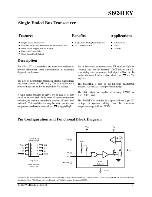
Benefits
D Single-Wire Multiplexer Interface D ISO Diagnosis Bus
Applications
D Automobiles D Trucks D Tractors
Description
The Si9241EY is a monolithic bus transceiver designed to provide bidirectional serial communication in automotive diagnostic applications. The device incorporates protection against overvoltages and short circuits to GND or VB. The transceiver pin is protected and can be driven beyond the VB voltage. A fault output provides an active low in case of a short circuit or an open load. In the event of an over temperature condition, the output is immediately switched off and a fault indicated. This condition can only be reset once the over temperature condition is removed, and CS is toggled high. For bi-directional communication, CS must be High for “receive” and Low for “transmit”. If CS is Low, while IC is receiving data, an incorrect fault signal will occur. To inhibit the open load and short detect, tie CS and TX together. The Si9241EY is built on the Siliconix BiC/DMOS process. An epitaxial layer prevents latchup. The RX output is capable of driving CMOS or 1 LSTTL load. The Si9241EY is available in a space efficient 8-pin SO package. It operates reliably over the automotive temperature range (–40 to 125_C).
- 1、下载文档前请自行甄别文档内容的完整性,平台不提供额外的编辑、内容补充、找答案等附加服务。
- 2、"仅部分预览"的文档,不可在线预览部分如存在完整性等问题,可反馈申请退款(可完整预览的文档不适用该条件!)。
- 3、如文档侵犯您的权益,请联系客服反馈,我们会尽快为您处理(人工客服工作时间:9:00-18:30)。
Applications
Isolated switch mode supplies Isolated ADC, DAC
Motor control Power factor correction systems
Safety Regulatory Approvals
UL recognition:2500 Vrms for 1 Minute per UL1577 CSA component acceptance notice
—
9
12
Si8421-A,-B,-C, VDD2
All inputs 0 DC
—
9
12
Si8421-A,-B,-C, VDD1
All inputs 1 DC
—
10
14
Si8421-A,-B,-C, VDD2
All inputs 1 DC
—
10
14
10 Mbps Supply Current (All inputs = 5 MHz square wave, CI = 15 pF on all outputs)
3.1. Theory of Operation . . . . . . . . . . . . . . . . . . . . . . . . . . . . . . . . . . . . . . . . . . . . . . . . . 19 3.2. Eye Diagram . . . . . . . . . . . . . . . . . . . . . . . . . . . . . . . . . . . . . . . . . . . . . . . . . . . . . . . 19 4. Layout Recommendations . . . . . . . . . . . . . . . . . . . . . . . . . . . . . . . . . . . . . . . . . . . . . . . . 20 4.1. Supply Bypass . . . . . . . . . . . . . . . . . . . . . . . . . . . . . . . . . . . . . . . . . . . . . . . . . . . . . 20 4.2. Input and Output Characteristics . . . . . . . . . . . . . . . . . . . . . . . . . . . . . . . . . . . . . . . . 21 4.3. RF Radiated Emissions . . . . . . . . . . . . . . . . . . . . . . . . . . . . . . . . . . . . . . . . . . . . . . . 21 4.4. RF Immunity and Common Mode Transient Immunity . . . . . . . . . . . . . . . . . . . . . . . 22 5. Pin Descriptions . . . . . . . . . . . . . . . . . . . . . . . . . . . . . . . . . . . . . . . . . . . . . . . . . . . . . . . . . 23 6. Ordering Guide . . . . . . . . . . . . . . . . . . . . . . . . . . . . . . . . . . . . . . . . . . . . . . . . . . . . . . . . . . 24 7. Package Outline: 8-Pin SOIC . . . . . . . . . . . . . . . . . . . . . . . . . . . . . . . . . . . . . . . . . . . . . . . 25 Contact Information . . . . . . . . . . . . . . . . . . . . . . . . . . . . . . . . . . . . . . . . . . . . . . . . . . . . . . . .26
—
Low Level Output Voltage
VOL
lol = 4 mA
—
0.2
0.4
Input Leakage Current
IL
—
—
±10
DC Supply Current (All inputs 0 V or at Supply)
Si8410-A,-B,-C, VDD1
All inputs 0 DC
I1 + I2 < 12 mA/channel at 100 Mbps Precise timing 2 ns pulse width distortion 1 ns channel-channel matching 2 ns pulse width skew
2500 VRMS isolation Transient Immunity
—
7
10
Si8420-A,-B,-C, VDD2
All inputs 0 DC
—
4
7
Si8420-A,-B,-C, VDD1
All inputs 1 DC
—
11
15
Si8420-A,-B,-C, VDD2
All inputs 1 DC
—
4
6
Si8421-A,-B,-C, VDD1
All inputs 0 DC
元器件交易网
Si8410/20/21
SINGLE & DUAL-CHANNEL DIGITAL ISOLATORS
Features
High-speed operation DC – 150 Mbps
Low propagation delay <10 ns
Wide Operating Supply Voltage: 2.375–5.5 V Low power
IEC certification conformity
IEC 60747-5-2 (VDE0884 Part 2)
Description
The Silicon Laboratories family of digital isolators are CMOS devices that employ an RF coupler to transmit digital information across an isolation barrier. Very high speed operation at low power levels is achieved. These parts are available in an 8-pin narrow-body SOIC package. Three speed grade options (1, 10, and 150 Mbps) are available and achieve typical propagation delays of less than 10 ns.
Preliminary Rev. 0.1
3
元器件交易网
Si8410/20/21
1. Electrical Specifications
Table 1. Electrical Characteristics
(VDD1 = 5 V, VDD2 = 5 V, TA = –40 to 125 ºC)
—
7
10
Si8410-A,-B,-C, VDD2
All inputs 0 DC
—
3
5
Si8410-A,-B,-C, VDD1
All inputs 1 DC
—
9
14
Si8410-A,-B,-C, VDD2
All inputs 1 DC
—
3
5
Si8420-A,-B,-C, VDD1
All inputs 0 DC
mA mA mA mA mA mA
mA mA mA mA mA mA
4
Preliminary Rev. 0.1
元器件交易网
Table 1. Electrical Characteristics (Continued)
(VDD1 = 5 V, VDD2 = 5 V, TA = –40 to 125 ºC)
>25 kV/µs DC correct No start-up initialization required <10 µs Startup Time High temperature operation
125 °C at 100 Mbps 100 °C at 150 Mbps Narrow body SOIC-8 package
Si8410-B,-C, VDD1
—
8
12
Si8410-B,-C, VDD2
—
5
7
Si8420-B,-C, VDD1
—
9
13
Si8420-B,-C, VDD2
—
9
12
Si8421-B,-C, VDD1
—
12
16
Si8421-B,-C, VDD2
—
12
16
100 Mbps Supply Current (All inputs = 50 MHz square wave, CI = 15 pF on all outputs)
元器件交易网
Si8410/20/21
2
Preliminary Rev. 0.1
