在multisim中新建LM386
multisim使用方法
multisim使用方法Multisim是一种用于电路设计和仿真的软件。
下面是使用Multisim的一般步骤:1. 打开软件:双击桌面上的Multisim图标或在启动菜单中找到并点击Multisim。
2. 创建新电路:在Multisim的欢迎界面上,选择“新电路设计”或点击“文件”菜单中的“新建电路”。
3. 添加元件:在工具栏上选择所需的元件,在电路图窗口中点击添加元件。
也可以使用右键菜单或快捷键来添加元件。
4. 连接元件:使用导线工具或连接工具在元件之间绘制电路线路。
确保正确连线以正确连接元件。
5. 设置电源:如果电路需要电源,则在工具栏上选择电源工具,并将其放置在电路图中恰当的位置上。
然后单击电源以更改其电压值和极性。
6. 设置测量器件:如果需要在仿真过程中测量电路的各个部分,则可以在工具栏上选择测量仪器并将其放置在电路图中。
7. 运行仿真:点击工具栏上的“运行”按钮或选择“仿真”菜单中的“运行”选项以开始仿真电路。
8. 分析仿真结果:仿真完成后,可以查看电路中各个元件的电流、电压等参数。
可以使用示波器、数字多表仪和其他工具来查看和分析仿真结果。
9. 保存和导出电路:在完成电路设计和仿真后,保存电路文件以便以后使用并导出仿真结果。
这些步骤只是Multisim使用的基本方法,你可以根据需要深入研究和探索更多功能和选项。
下面是Multisim的使用方法:1. 创建新项目:打开Multisim软件后,点击“File”菜单,选择“New”,然后选择“New Project”来创建一个新项目。
2. 添加器件:在项目中添加所需的器件。
点击“Component”菜单,选择“Place”来添加各种电子器件。
3. 连接电路:通过拖拽连接线将器件连接在一起,形成电路。
点击“Wire”工具,然后依次选中各个器件的引脚来连接它们。
4. 设定电流/电压源:点击“Source”工具,选择合适的电流或电压源来为电路提供电源。
智能产品LM386音频放大电路的设计与制作
LM386音频放大电路的设计与制作1、概述1.1、音频功率放大器产品功能音频功率放大器是通过功率放大器(简称功放)给音频放大器的负载RL(扬声器)提供一定的输出功率。
当负载一定时,希望输出的功率尽可能大,输出信号的非线性失真尽可能地小,效率尽可能高。
1.2、性能指标1.2.1、信噪比(S/N)又称为讯噪比,信号的有用成份与杂音的强弱对比,常常用分贝数表示。
设备的信噪比越高表明它产生的杂音越少。
1.2.2、灵敏度对放大器来说,灵敏度一般指达到额定输出功率或电压时输入端所加信号的电压大小,因此也称为输入灵敏度;对音箱来说,灵敏度是指给音箱施加1W的输入功率, 在喇叭正前方1米远处能产生多少分贝的声压值。
1.2.3、阻尼系数负载阻抗与放大器输出阻抗之比。
使用负反的晶体管放大器输出阻抗极低,仅零点几欧姆甚至更小,所以阻尼系数可达数十到数百。
1.2.4、动态范围信号最强的部分与最微弱部分之间的电平差.对器材来说,动态范围表示这件器材对强弱信号的兼顾处理能力。
1.2.5、响应频率响应:简称频响,衡量一件器材对高、中、低各频段信号均匀再现的能力。
对器材频响的要求有两方面,一是范围尽量宽,即能够重播的频率下限尽量低,上限尽量高;二是频率范围内各点的响应尽量平坦,避免出现过大的波动。
1.2.6、屏蔽在电子装置或导线的外面覆盖易于传导电磁波的材料,以防止外来电磁杂波对有用信号产生干扰的技术。
1.3、生产成本电路简单,成本不高。
1.4、应用领域甲类功放失真最小,效率最低,发热最大。
功率不易做的很大。
乙类功放正负半周分别放大(推挽),引入多种失真,但效率高。
甲乙类功放小信号时工作于甲类大信号时工作于乙类,兼顾失真和效率,是目前主流功放类型,合理设计电路精选元器件,可以做出很高的指标。
丁类功放就是近年来兴起的数字功放,有极高的效率,也有相当高的技术指标,广泛用于小型电子产品中,比如汽车音响中。
但丁类功放在音响发烧友中还没有得到普遍认可。
在NIMultisim中创建自定义元器件(精)
在NIMultisim中创建自定义元器件(精)概览:NI Multisim 与NI Ultiboard为设计、仿真和布局完整的印制电路板(PCB)提供了一个集成的平台。
高度灵活的数据库管理程序,使得为自定义原理图符号添加新的SPICE仿真模型变得十分方便,该原理图符号可用于将精确的封装转换为布局。
在NI Multisim中创建自定义元器件与在NI Ultiboard中创建自定义元器件为您提供了关于如何直观、快速地学习如何创建您自己的自定义元器件的信息资源。
引言:本指南是关于在NI Multisim 与NI Ultiboard上创建元器件的系列文章的第一篇。
本指南旨在阐述您如何可以在Multisim中创建您自己的用于仿真和/或印制电路板(PCB)布局的元器件。
您将可以创建元器件并验证其操作。
元器件向导是用于创建自定义元器件的主要工具,它引导您完成创建一个新元器件所需要的所有步骤。
元器件细节包括符号与可选的管脚、模型和管封装信息。
某元器件创建过程包括以下步骤:•输入元器件信息•选择封装与元器件配置•选择和/或编辑元器件符号•设置管脚参数•将符号管脚映射至封装管脚•选择仿真模型•将符号管脚映射至模型管脚•将其保存于数据库该指南逐步引导您完成创建一个与仿真和PCB布局兼容的元器件的过程。
为完整起见,您将学习如何创建一个有2个部件的高级元器件。
您将创建一个具有两个原理图符号、两个模型但只有一个封装的部件。
许多元器件可以更方便地被创建,在大多数情况下这里列出的步骤并不是全部必需的。
Multisim也支持用户创建仅用于仿真或仅用于布局的元器件。
元器件创建系列文章的第二部分——名为《在NI Ultiboard中创建自定义元器件》,简述了如何构建一个用于布局的自定义Ultiboard焊盘图形。
该焊盘图形由手工创建,以便精确定义表面贴装元件(SMD)的形状、尺寸和大小。
该封装可添加至Multisim数据库以定义一个自定义元器件。
智能产品LM386音频放大电路的设计和制作
技术资料LM386音频放大电路的设计与制作1、概述1.1、音频功率放大器产品功能音频功率放大器是通过功率放大器(简称功放)给音频放大器的负载RL(扬声器)提供一定的输出功率。
当负载一定时,希望输出的功率尽可能大,输出信号的非线性失真尽可能地小,效率尽可能高。
1.2、性能指标1.2.1、信噪比(S/N)又称为讯噪比,信号的有用成份与杂音的强弱对比,常常用分贝数表示。
设备的信噪比越高表明它产生的杂音越少。
1.2.2、灵敏度对放大器来说,灵敏度一般指达到额定输出功率或电压时输入端所加信号的电压大小,因此也称为输入灵敏度;对音箱来说,灵敏度是指给音箱施加1W的输入功率, 在喇叭正前方1米远处能产生多少分贝的声压值。
1.2.3、阻尼系数负载阻抗与放大器输出阻抗之比。
使用负反的晶体管放大器输出阻抗极低,仅零点几欧姆甚至更小,所以阻尼系数可达数十到数百。
1.2.4、动态范围信号最强的部分与最微弱部分之间的电平差.对器材来说,动态范围表示这件器材对强弱信号的兼顾处理能力。
1.2.5、响应频率响应:简称频响,衡量一件器材对高、中、低各频段信号均匀再现的能力。
对器材频响的要求有两方面,一是范围尽量宽,即能够重播的频率下限尽量低,上限尽量高;二是频率范围内各点的响应尽量平坦,避免出现过大的波动。
1.2.6、屏蔽在电子装置或导线的外面覆盖易于传导电磁波的材料,以防止外来电磁杂波对有用信号产生干扰的技术。
1.3、生产成本电路简单,成本不高。
1.4、应用领域甲类功放失真最小,效率最低,发热最大。
功率不易做的很大。
乙类功放正负半周分别放大(推挽),引入多种失真,但效率高。
甲乙类功放小信号时工作于甲类大信号时工作于乙类,兼顾失真和效率,是目前主流功放类型,合理设计电路精选元器件,可以做出很高的指标。
丁类功放就是近年来兴起的数字功放,有极高的效率,也有相当高的技术指标,广泛用于小型电子产品中,比如汽车音响中。
但丁类功放在音响发烧友中还没有得到普遍认可。
一个LM386简单功放电路图
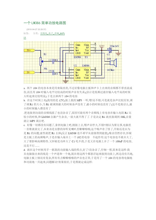
一个LM386简单功放电路图(2010-04-27 22:29:37)分类:无线电_电子_音响_HiFi标签:ita. 两个104的电容本来是用来隔直的,不过好像电脑主板和声卡上出来的音频都不带直流成份,而且用104时输入电平比较高的时候声音有失真,(估计是低频过滤在输入电平高的时候人听起来比较明显).于是去掉两个104的电容.b. 在这个时候上电(我用的是12V),接上我的MP3一听,嗯!还不错,可是就是杂声比较厉害,调了调R1的大小,当R1被调到最大的时候杂声没有了,最小的时候也没有了(这不是废话么,最小的时候输入都没有了.把连接到功放的音频线拔了也没杂音了,原因可能有两个音频线上有电容在输入电阻R1比较小的时候,和LM386自激产生杂音,一放大就不得了了.于是决定R1就直接调到50K,音量就让MP3调去吧.c. 好像一切都没有问题了,拿到电脑上吧,刚接上去,嗯声音停大,不错!!刚以为要完事,电脑里一首歌就放完了,本来该是安静的却听见喇叭里噼噼啪啪,这个噪声奇了怪了,开始还是以为是R1的问题,索性就把R1去掉(反正LM386也不希罕从前级得到能量),噪音仍然存在,怀疑是主板上的高频噪声,于是在输入端并上一个102的电容---不起作用.这个电容也不敢并大了,大了要影响高频特性.又怀疑是功率大了C1吃不消,于是又在电源上并了一个100uF的电容,还是不行.......d. 就在这个时候用手一抓我的功放输入端的焊点,好了!没杂音了,仔细一想,原来是这样:我从电脑接出来的线是一个声道和一个地,现在将这两个都悬浮起来接到功放上,两边没有共地,电脑主板上情况有复杂,所有有点噼噼啪啪的声音也正常,于是用了一个104的电容将电脑地和功放地一共起来,问题解决!效果很好,于是图就定成这样:3.建议以我使用的LM386-N1为标准的建议a. 供电,除非你保证你的供电是标准的12V,要不你就用9V.毕竟极限电压就在15V上b.两个LM386一定要是同一批次出来的,这样对称性比较好,你要是用不同厂家的386来做BTL,哪就等着听嗡嗡声吧c.LM386的增益其实可以通过在1,8两脚之间加电容来调的,如果是不接东西386的增益是最大的.所以用BTL电路没事也就别调什么放大倍数了吧d.LM386-N1的输出功率不大,所以输入的幅度不要搞得太狠,虽然在我的电脑上把声音开到最大还没烧片子,但是也热得可以,所以还是适可而止吧(具体参数我也没测试)e.如果声音比较大还是建议吧C1用到330uF以上.算算价格:LM386一片1块一共两块,电解电容3毛,瓷片电容5分,弄上一小块万用板也就2块不到,一共算4块钱吧,如果想低音听得爽些,花点血本买个带橡皮圈的内磁喇叭吧也就8块左右.一个单声道功放12块搞定,立体声就是24块.效果绝对不差。
[lm386功放电路图]lm386制作的随身听、小功放电路
![[lm386功放电路图]lm386制作的随身听、小功放电路](https://img.taocdn.com/s3/m/71b47f25366baf1ffc4ffe4733687e21af45ffc7.png)
[lm386功放电路图]lm386制作的随身听、小功放电路扩音机的实验可以作为随身听、微弱信号放大器,当你在家自制一扩音机,把随身听中美妙的音乐通过扩音机放出,不再用耳机,你不觉很有成就感吗?扩音机的基本原理是利用功放集成电路LM386进行控制,其电路原理图如图1所示。
lm386的功放电路电路原理LM386由于它的应用广泛,有万能功放电路之称。
它的工作电压范围宽,最小为4V,最大为15V。
静态功耗为4mA,最大增益为46dB,即200倍。
LM386的封装形式如图2所示,它有2个输入端:同相输入端3脚和反相输入端2脚,输入信号可从任意端输入,将另1个输入端接地。
增益控制端为1、8脚,调整RP2可调整增益高低。
5脚为功放输出端,R与C4组成高频衰减电路以提高音质。
7脚接C3,避免增益过高时产生自激。
6脚接电源正极,4脚接地。
LM()386引脚图LM386实物图篇二 : LM386应用电路实例_LM386简单功放电路图之前写了简单的延时电路_RC电阻电容延时电路,很多朋友很表示很有用,这次写点别的。
LM386这主要是个音频放大芯片,说白了就是放大声音的。
具体的引脚介绍可以看器件手册,毕竟这个是最权威的,查询器件手册的网址是datasheet5,百度一搜就是。
芯片分为几个系列,有M系列,有N系列:LM386N-1,LM386M-1,LM386美眉-1,供电电压6V,负载8欧姆,最大功率0.325W;LM386N-3,电压9V,负载8欧姆,最大功率0.7W;LM386N-4,电压16V,负载32欧姆,最大功率1W。
敲这些型号很累,我就不写了,具体参数看文档。
这个电路是用到光话机上面的,本来只用耳麦就好了,但是老板一定要加外放。
于是就想到了386.看了下器件手册,挺简单的1个芯片,照着图接就行了,根本没啥难度。
但是,我用的声音信号是从MIC里过来的,然后板子上供电电压稳定的只有5V,所以单功放声音不给力,我用了双功放的电路。
multisim教程
multisim教程以下是Multisim的简单教程:Multisim是一款用于电子电路仿真和设计的软件工具。
下面我将介绍一些基本的操作步骤,帮助你开始使用Multisim。
1. 打开Multisim软件并创建新项目。
选择“File”菜单中的“New”选项,然后选择“New Design”来创建一个新的电路设计。
2. 选择器件进行电路设计。
在“Place”菜单中选择合适的器件,如电阻、电容、二极管等,并将它们拖放到电路图板上。
3. 连接器件。
使用连线工具将器件彼此连接起来,这样就可以形成一个完整的电路。
确保连接正确,以保证电路的功能。
4. 设定器件参数。
双击选择的器件,在弹出的属性框中设置相应的参数,如电阻值、电容大小等。
5. 运行仿真。
选择“Simulate”菜单中的“Run”选项,或使用工具栏上的仿真按钮来运行仿真。
Multisim将模拟电路的行为,并显示电路的响应结果。
6. 分析仿真结果。
查看仿真结果,包括电流、电压、功率等参数。
这些结果将帮助你评估电路的性能和功能。
7. 调整和改进电路设计。
根据仿真结果,你可以对电路进行优化和改进。
调整参数、更换器件或重新设计电路布局,以达到设计要求。
8. 保存和导出设计。
将设计保存为Multisim项目文件,以便后续修改和使用。
如果需要,你还可以导出电路图、仿真结果等。
请注意,以上步骤仅为基础操作示例。
Multisim是一款功能强大的软件工具,还提供许多高级功能和特性,如多工程协作、电路板布局等。
你可以进一步学习和探索这些功能,以扩展你的电子电路设计能力。
llm386内部电路图_m386音频放大电路原理图解
llm386内部电路图_m386音频放大电路原理图解每个人的心中都有那么一块芯片:你对它了如指掌,典型应用电路烂熟于胸,一旦出现了某种需求立刻就能想到它。
虽然它可能早已不是完成任务的最佳选择,但是你总是割舍不下它。
不同的人有不同的答案。
但是对于模拟音频放大领域,这片芯片一般是LM386。
虽然它很老,需要外置部分元件才能获得最好效果,噪声也不满足高保真的需求,而且也不支持时兴的3.3V供电。
但是如果你经常自己动手做一些会发出声音的小电路的话,那么这片芯片肯定是你的首选。
进入现代,低电压和锂电池供电的时代,有很多时兴的音频放大芯片可以供你选择。
甚至在3.3V供电的电路中也有适合使用的放大器芯片。
这种芯片一般以桥式负载的方式连接进电路——即同时驱动扬声器的两边,这样会提供更好的输出效果。
并省去了输出级的大电容。
同理,这种芯片一般用于内部空间有限的电子设备里,并多采用贴片封装。
在这个领域内竞争,LM386没有任何机会。
然而,如果你不擅长焊接贴片封装、对空间没有要求,或是只需要用面“扶我起来,包板搭建设计原型,那么LM386仍然是设计的一把好手。
我还可以再战!”基本电路LM386——作为一片老将级芯片,一直生产到现在并不是只是因为其常见的DIP封装,真正的原因在于其过硬的设计思路。
它的内部是一个典型的推挽式放大器(又称推拉式),其主要结构由两个输出晶体管组成,其中一个用来放大电压波形的上半边,而另一个则用来放大电压波形的下半边。
问题在于,这样的设计可能出现交越失真,通过良好的调整三极管的工作区域,可以尽量消除该现象。
你也可以使用一只运算放大器来提供反馈,并使其退出这个死区。
在LM386里,这两种方式都有采用。
如果LM386这种神奇的芯片不存在,而你又想实现这样的功能,该怎么办呢?你可以使用一只优秀的运算放大器来进行电压放大,并使用两只组成图腾柱结构的三极管构成提供电流的部分。
这样所组成的电路起到的作用和LM386是一样的。
制作简单的LM386吉他音箱放大器
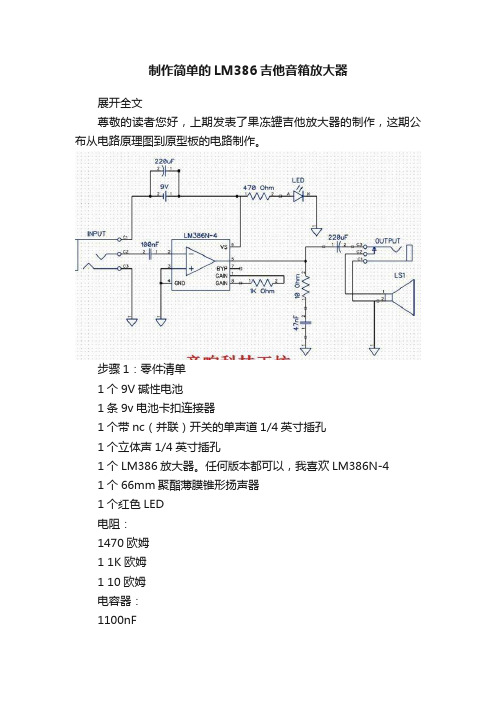
制作简单的LM386吉他音箱放大器展开全文尊敬的读者您好,上期发表了果冻罐吉他放大器的制作,这期公布从电路原理图到原型板的电路制作。
步骤1:零件清单1个9V碱性电池1条9v电池卡扣连接器1个带nc(并联)开关的单声道1/4英寸插孔1个立体声1/4英寸插孔1个LM386放大器。
任何版本都可以,我喜欢LM386N-41个66mm聚酯薄膜锥形扬声器1个红色LED电阻:1470欧姆1 1K欧姆1 10欧姆电容器:1100nF1 47nF2220uF洞洞板烙铁和焊锡步骤2:洞洞板这种洞洞板是为集成电路制作的,方便引线和焊接。
零件都含在没有铜箔的一面。
最好是先规划一下,免得走线混乱引起错误。
步骤3:将原理图转换为原型板因此,一旦您设计好电路并制作了原理图,就可以开始研究原型板的布局了。
您将铅笔拿到纸上,然后开始在protoboard插图上布置组件。
这需要一些技巧。
需要一些时间。
这将花费大量的纸张。
在上方,您可以看到原理图和原型板上的成品轮廓。
计划原型板上的组件位置时,我会分阶段进行计划。
我将从芯片的放置开始。
我从左到右工作,所以我将布局如下:输入---- IC芯片----输出该电路的输入非常简单,因此芯片将放置在原型板的左侧。
这为输出组件留出了空间。
下一步是布置电路的所有电源。
下一步是布置输入和输出组件。
下一步是添加增益组件和LED电源指示灯下一步是添加外围组件,例如输入和输出插孔。
每个阶段都建立在最后一个阶段。
从最简单到更复杂。
分阶段进行构建可以使您在进行过程中进行测试和故障排除,以便在出现错误的情况下更早发现并可以将其与构建中的先前阶段隔离开来。
将原理图转换为原型板图之后,就该构建真正的电路了。
我将原型板图分解成几张纸,每张纸都包含一个阶段或构建的一部分。
因此,我可以打印出构建的每个部分,并在进行过程中检查放置在真实原型板上的组件,以确保没有遗漏任何东西。
这对于复杂的构建尤其重要。
对于此特定电路,我们将分4部分进行构建。
MULTISIM电路仿真软件的使用操作教程
MULTISIM电路仿真软件的使用操作教程Multisim是一款功能强大的电路仿真软件,可以帮助用户进行电路设计、分析和仿真。
在本教程中,我们将介绍Multisim的基本使用操作,让您可以快速上手并开始进行电路仿真。
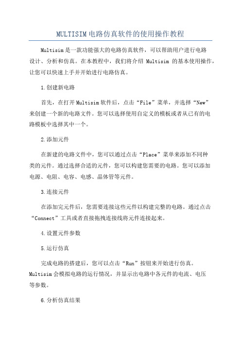
1.创建新电路首先,在打开Multisim软件后,点击“File”菜单,并选择“New”来创建一个新的电路文件。
您可以选择使用自定义的模板或者从已有的电路模板中选择其中一个。
2.添加元件在新建的电路文件中,您可以通过点击“Place”菜单来添加不同种类的元件。
通过选择合适的元件,您可以构建您需要的电路。
您可以添加电源、电阻、电容、电感、晶体管等元件。
3.连接元件在添加完元件后,您需要连接这些元件以构建完整的电路。
通过点击“Connect”工具或者直接拖拽连接线将元件连接起来。
4.设置元件参数5.运行仿真完成电路的搭建后,您可以点击“Run”按钮来开始进行仿真。
Multisim会模拟电路的运行情况,并显示出电路中各元件的电流、电压等参数。
6.分析仿真结果在进行仿真后,您可以查看仿真结果并进行分析。
您可以查看波形图、数据表格等来了解电路的运行情况,以便进行进一步的优化和改进。
7.保存电路文件在完成电路设计后,您可以点击“File”菜单并选择“Save As”来保存电路文件。
您可以选择保存为不同格式的文件,以便将电路文件与他人分享或者备份。
8.导出报告如果您需要将电路设计的结果进行报告或者分享给他人,您可以点击“Tools”菜单并选择“Export”来导出报告或者数据表格。
9.调整仿真设置在进行仿真前,您可以点击“Options”菜单来调整仿真的参数,例如仿真时间、采样率等。
这可以帮助您更好地分析电路的性能。
10.学习资源Multisim提供了大量的学习资源,包括用户手册、视频教程、示例项目等。
您可以通过点击“Help”菜单来访问这些资源,以帮助您更好地使用Multisim进行电路仿真。
通过以上教程,您可以快速上手Multisim软件,并开始进行电路设计和仿真。
lm386课程设计
lm386课程设计一、课程目标知识目标:1. 学生能理解LM386音频放大器的原理与功能,掌握其内部结构及工作流程。
2. 学生能描述LM386在音频放大电路中的应用,了解其优点和局限性。
3. 学生掌握LM386相关参数的计算和调整方法,能够根据实际需求设计合适的音频放大电路。
技能目标:1. 学生能够独立完成LM386音频放大器的焊接、调试和测试,提高动手实践能力。
2. 学生能够运用所学知识,解决实际音频放大电路中可能出现的问题,具备一定的故障排查能力。
3. 学生能够通过团队合作,完成一个具有实际应用的LM386音频放大电路设计,提高沟通与协作能力。
情感态度价值观目标:1. 学生对电子技术产生兴趣,培养探索精神和创新意识。
2. 学生认识到团队合作的重要性,树立团队协作的意识。
3. 学生在实践过程中,体会电子技术在实际生活中的应用,增强学以致用的观念。
课程性质:本课程为电子技术实践课程,旨在帮助学生将理论知识与实际应用相结合,提高学生的动手实践能力。
学生特点:学生处于高中阶段,具有一定的电子技术基础知识,对实践操作充满好奇,但动手能力参差不齐。
教学要求:注重理论与实践相结合,强调动手实践,培养学生解决问题的能力。
在教学过程中,关注学生个体差异,提供个性化指导,确保每位学生都能达到课程目标。
二、教学内容本章节教学内容主要包括以下三个方面:1. LM386音频放大器原理与结构- 了解放大器的分类及基本工作原理- 学习LM386内部结构,掌握其主要功能- 分析LM386的优缺点,了解其在音频放大电路中的应用2. LM386参数计算与调整- 学习LM386相关参数的计算方法,如增益、带宽等- 掌握LM386外围元件的选择与调整,以满足不同应用需求- 了解LM386在实际应用中的注意事项,确保电路稳定可靠3. LM386音频放大器实践操作- 学习焊接、调试和测试LM386音频放大器的方法- 通过团队合作,设计并实现一个具有实际应用的音频放大电路- 分析并解决实践过程中可能出现的问题,提高学生的动手实践能力教学内容安排与进度:1. 第1课时:介绍放大器原理与LM386内部结构,分析优缺点及应用2. 第2课时:讲解LM386参数计算与调整方法,进行外围元件选择与调整3. 第3课时:实践操作,焊接、调试和测试LM386音频放大器4. 第4课时:团队合作,设计并实现音频放大电路,分析解决问题教材章节关联:本教学内容与教材中“音频放大器”章节相关,涉及LM386的原理、应用与实践操作。
lm386-电路原理---音频放大器

lm386-电路原理---音频放大器
lm386是一种常用的音频放大器,适用于低功率音响系统和电子设备。
它的特点是简
单易懂,工作可靠,价格低廉,在DIY音响的世界中广泛应用。
那么,它的电路原理是什
么呢?
lm386的电路原理可以简单地分为两部分,输入放大器和输出放大器。
输入放大器:
输入放大器是一种放大器电路,把输入信号的电压放大,输出电压变成一个更高的信号,经过一个低通滤波器后去除高频噪声。
在lm386中,输入信号通过C1电容进入放大器,并且经过R1和R2电阻分压降低信号电平。
接着信号通过放大器U1的非反向输入端,通过R3电阻形成负反馈,使放大器的放大倍数稳定,同时降低了噪声。
输出放大器将放大后的信号通过一个大功率晶体管输出到喇叭,将电信号转换成声音。
在lm386中,输出放大器也采用负反馈控制的方式,控制输出电压,稳定功率。
U1的输出通过C4电容进入输出级别放大器,驱动晶体管Q1的基极。
经过高通滤波器C8,将基极引到电源电压的一半,同时降低直流偏置。
晶体管Q1的输出将声音发出,同时反馈到放大器的非反向输入。
总体来说,lm386基本是一个放大器电路,通过输入和输出放大器的组合,可以实现
低功率的音频放大。
除了基本的电路原理,还可以结合其他元件组合出多种不同的效果,
如有源音量控制、三合一音量控制、失真音效等等。
从硬件上选择经典的 lm386芯片,再结合趣味DIY的组合美学,很容易得出简单、实用和覆盖大部分音响需求的二合一放大器
方案。
lm386功放电路

lm386功放电路1. 引言LM386是一种经典的音频功放集成电路,被广泛应用在各种电子设备中,例如收音机、音响、喇叭和各种便携式音频设备。
它具有简单的设计和低成本的特点,并且能够提供足够的功率输出,适用于一般的音频放大应用。
本文将介绍如何设计和组装一个基本的LM386功放电路,并提供相应的电路图和材料清单。
2. 器件清单在准备组装LM386功放电路之前,我们需要准备以下器件和材料:•LM386集成电路芯片•电容:0.1μF x 2、10μF x 1•电阻:10Ω、4.7kΩ、220Ω•电感(可选):10mH•音频输入接口(例如3.5mm音频插头)•扬声器•杜邦线•面包板•电源(可以是直流电源适配器或者电池)3. 电路原理电路图电路图4. 电路设计和组装步骤步骤1:连接电容和电阻1.在面包板上找到一个行数足够长的行,并在其两端分别连接10μF电容。
这两个电容将作为输入和输出的耦合电容。
2.将4.7kΩ电阻连接到输入耦合电容的负极。
3.将220Ω电阻连接到输出耦合电容的负极。
步骤2:连接IC芯片1.将LM386芯片插入面包板上的合适位置。
确保芯片的引脚与面包板上的行连接。
2.将芯片的引脚1连接到输入耦合电容的正极。
3.将芯片的引脚2连接到地线(用黑色杜邦线表示)。
4.将芯片的引脚3连接到电源正极(用红色杜邦线表示)。
5.将芯片的引脚4连接到输出耦合电容的正极。
6.将芯片的引脚5连接到地线。
7.将芯片的引脚6连接到步骤1中连接的220Ω电阻。
8.将芯片的引脚7连接到地线。
9.将芯片的引脚8连接到正极扬声器。
步骤3:连接音频输入1.获得一个3.5mm音频插头,并连接它到步骤1中连接的4.7kΩ电阻的另一端。
2.在面包板上选择一个合适的位置,连接插头的引脚到步骤1中连接的4.7kΩ电阻的另一端。
步骤4:可选的电感连接1.如果需要对音频信号进行额外的滤波和增强,可以将一个10mH电感连接到步骤1中连接的10μF电容之间。
LM386音频放大电路的设计与制作
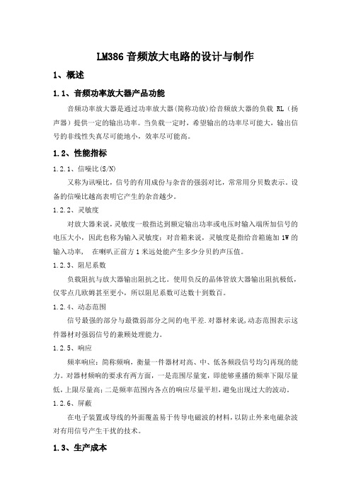
LM386音频放大电路的设计与制作1、概述1.1、音频功率放大器产品功能音频功率放大器是通过功率放大器(简称功放)给音频放大器的负载RL(扬声器)提供一定的输出功率。
当负载一定时,希望输出的功率尽可能大,输出信号的非线性失真尽可能地小,效率尽可能高。
1.2、性能指标1.2.1、信噪比(S/N)又称为讯噪比,信号的有用成份与杂音的强弱对比,常常用分贝数表示。
设备的信噪比越高表明它产生的杂音越少。
1.2.2、灵敏度对放大器来说,灵敏度一般指达到额定输出功率或电压时输入端所加信号的电压大小,因此也称为输入灵敏度;对音箱来说,灵敏度是指给音箱施加1W的输入功率, 在喇叭正前方1米远处能产生多少分贝的声压值。
1.2.3、阻尼系数负载阻抗与放大器输出阻抗之比。
使用负反的晶体管放大器输出阻抗极低,仅零点几欧姆甚至更小,所以阻尼系数可达数十到数百。
1.2.4、动态范围信号最强的部分与最微弱部分之间的电平差.对器材来说,动态范围表示这件器材对强弱信号的兼顾处理能力。
1.2.5、响应频率响应:简称频响,衡量一件器材对高、中、低各频段信号均匀再现的能力。
对器材频响的要求有两方面,一是范围尽量宽,即能够重播的频率下限尽量低,上限尽量高;二是频率范围内各点的响应尽量平坦,避免出现过大的波动。
1.2.6、屏蔽在电子装置或导线的外面覆盖易于传导电磁波的材料,以防止外来电磁杂波对有用信号产生干扰的技术。
1.3、生产成本电路简单,成本不高。
1.4、应用领域甲类功放失真最小,效率最低,发热最大。
功率不易做的很大。
乙类功放正负半周分别放大(推挽),引入多种失真,但效率高。
甲乙类功放小信号时工作于甲类大信号时工作于乙类,兼顾失真和效率,是目前主流功放类型,合理设计电路精选元器件,可以做出很高的指标。
丁类功放就是近年来兴起的数字功放,有极高的效率,也有相当高的技术指标,广泛用于小型电子产品中,比如汽车音响中。
但丁类功放在音响发烧友中还没有得到普遍认可。
简易电子琴(NE555,LM386)

课程设计说明书课程设计名称:模拟电路课程设计课程设计题目:简易电子琴模拟电路课程设计任务书题目简易电子琴内容及要求①产生e调8个音阶的振荡频率,分别由1、2、3、4、5、6、7、0号数字键控制;②其频率分别为:1:261.6、2:293.6、3:329.6、4:349.2、5:392.0、6:440.0、7:439.9、0:523;③利用集成功放放大该信号,驱动扬声器;④设计一声调调节电路,改变生成声音的频率。
进度安排第7周:查阅资料,学习仿真软件,确定方案,完成原理图设计及仿真;第8周:领元器件、仪器设备,制作、焊接、调试电路,完成系统的设计;第9周:检查设计结果、撰写课设报告。
音乐在人类社会扮演着重要的角色,传统的乐器学习难度大且价格高昂,而一些简易的电子乐器价格相对便宜,能满足一般爱好者需求。
故研制电子乐器具有一定社会意义。
本次课程设计中,采用NE555和LM386功率放大器来完成设计要求。
利用555定时器构成多谐振荡器,通过8个按键控制不同的RC组合使其产生不同频率八个基本音阶的脉冲信号波,通过LM386功率放大器驱动扬声器,即可发出八个音阶的音乐。
关键词:简易电子琴、NE555、LM386、8个音阶第一章系统组成 (1)1.1系统框图 (1)1.2系统介绍 (1)第二章各模块设计 (2)2.1按键开关模块 (2)2.2振荡器模块 (2)2.3扬声器模块 (3)第三章仿真图及分析 (4)3.1仿真波形图 (4)3.2仿真结果分析 (7)第四章设计结果分析 (8)第五章实验小结 (9)参考文献 (10)附录A 元件清单 (11)附录B 焊接实物图 (12)第一章 系统组成1.1系统框图图1.1系统框图采用555集成定时器组成简易电子琴,整个电路由振荡器、LM386功放器、扬声器和按键开关等部分组成。
主振荡器是由555定时器,八个按键开关,外接电容C1、C2,外接电阻R8以及R1-R7(用8个可调电阻调成所需电阻元件)等元件组成。
智能产品LM386音频放大电路的设计与制作

LM386音频放大电路的设计与制作1、概述1.1、音频功率放大器产品功能音频功率放大器是通过功率放大器(简称功放)给音频放大器的负载RL (扬声器)提供一定的输出功率。
当负载一定时,希望输出的功率尽可能大,输出信号的非线性失真尽可能地小,效率尽可能高。
1.2、性能指标1.2.1 、信噪比(S/N)又称为讯噪比,信号的有用成份与杂音的强弱对比,常常用分贝数表示。
设备的信噪比越高表明它产生的杂音越少。
1.2.2 、灵敏度对放大器来说,灵敏度一般指达到额定输出功率或电压时输入端所加信号的电压大小,因此也称为输入灵敏度;对音箱来说,灵敏度是指给音箱施加1W的输入功率, 在喇叭正前方 1 米远处能产生多少分贝的声压值。
1.2.3、阻尼系数负载阻抗与放大器输出阻抗之比。
使用负反的晶体管放大器输出阻抗极低,仅零点几欧姆甚至更小,所以阻尼系数可达数十到数百。
1.2.4、动态范围信号最强的部分与最微弱部分之间的电平差.对器材来说,动态范围表示这件器材对强弱信号的兼顾处理能力。
1.2.5 、响应频率响应:简称频响,衡量一件器材对高、中、低各频段信号均匀再现的能力。
对器材频响的要求有两方面,一是范围尽量宽,即能够重播的频率下限尽量低,上限尽量高;二是频率范围内各点的响应尽量平坦,避免出现过大的波动。
1.2.6 、屏蔽在电子装置或导线的外面覆盖易于传导电磁波的材料,以防止外来电磁杂波对有用信号产生干扰的技术。
1.3、生产成本电路简单,成本不咼。
1.4、应用领域甲类功放失真最小,效率最低,发热最大。
功率不易做的很大。
乙类功放正负半周分别放大(推挽),引入多种失真,但效率高。
甲乙类功放小信号时工作于甲类大信号时工作于乙类,兼顾失真和效率,是目前主流功放类型,合理设计电路精选元器件,可以做出很高的指标。
丁类功放就是近年来兴起的数字功放,有极高的效率,也有相当高的技术指标,广泛用于小型电子产品中,比如汽车音响中。
但丁类功放在音响发烧友中还没有得到普遍认可。
multisim搭建搭建电路和测量电路参数的方法

multisim搭建搭建电路和测量电路参数的方
法
Multisim是一款功能强大的电子电路仿真软件,用于搭建电路和测量电路参数。
在使用Multisim搭建电路和测量电路参数之前,你需要按照以下步骤进行操作:
1. 打开Multisim软件并创建一个新的电路文件。
你可以选择从库中选择元件进行拖放,或者使用绘图工具手动画出电路图。
2. 添加所需的电子元件。
Multisim库中包含了各种电子元件,如电阻、电容、
电感、二极管、晶体管等。
你可以通过在库搜索栏中输入元件名称来快速找到并添加。
3. 连接电路元件。
使用线缆工具在电路图中连接电子元件,确保电路的连通性
和正确性。
4. 设置电源和仪器。
为电路添加适当的电源和测量仪器,如电压源、电流源、
示波器等。
5. 设置元件的值和参数。
双击元件,在弹出的属性窗口中设置元件的值和参数,如电阻值、电容值等。
6. 运行仿真。
点击“运行”按钮开始仿真,Multisim将模拟电路的行为并计算各
个元件的参数。
7. 查看测量结果。
仿真完成后,可以通过示波器、表格等工具查看电路中各个
元件的电压、电流等参数。
8. 分析和优化电路。
根据测量结果,你可以对电路进行进一步分析和优化,如
调整元件值、改变连接方式等,以满足电路设计的要求。
通过上述方法,你可以成功搭建电路并测量电路参数。
Multisim提供了强大的仿真功能,可帮助工程师和学生更好地理解电路行为,并进行电路设计和优化。
简易电子琴(NE555,LM386)

课程设计说明书课程设计名称:模拟电路课程设计课程设计题目:简易电子琴模拟电路课程设计任务书题目简易电子琴内容及要求①产生e调8个音阶的振荡频率,分别由1、2、3、4、5、6、7、0号数字键控制;②其频率分别为:1:261.6、2:293.6、3:329.6、4:349.2、5:392.0、6:440.0、7:439.9、0:523;③利用集成功放放大该信号,驱动扬声器;④设计一声调调节电路,改变生成声音的频率。
进度安排第7周:查阅资料,学习仿真软件,确定方案,完成原理图设计及仿真;第8周:领元器件、仪器设备,制作、焊接、调试电路,完成系统的设计;第9周:检查设计结果、撰写课设报告。
音乐在人类社会扮演着重要的角色,传统的乐器学习难度大且价格高昂,而一些简易的电子乐器价格相对便宜,能满足一般爱好者需求。
故研制电子乐器具有一定社会意义。
本次课程设计中,采用NE555和LM386功率放大器来完成设计要求。
利用555定时器构成多谐振荡器,通过8个按键控制不同的RC组合使其产生不同频率八个基本音阶的脉冲信号波,通过LM386功率放大器驱动扬声器,即可发出八个音阶的音乐。
关键词:简易电子琴、NE555、LM386、8个音阶第一章系统组成 (1)1.1系统框图 (1)1.2系统介绍 (1)第二章各模块设计 (2)2.1按键开关模块 (2)2.2振荡器模块 (2)2.3扬声器模块 (3)第三章仿真图及分析 (4)3.1仿真波形图 (4)3.2仿真结果分析 (7)第四章设计结果分析 (8)第五章实验小结 (9)参考文献 (10)附录A 元件清单 (11)附录B 焊接实物图 (12)第一章 系统组成1.1系统框图图1.1系统框图采用555集成定时器组成简易电子琴,整个电路由振荡器、LM386功放器、扬声器和按键开关等部分组成。
主振荡器是由555定时器,八个按键开关,外接电容C1、C2,外接电阻R8以及R1-R7(用8个可调电阻调成所需电阻元件)等元件组成。
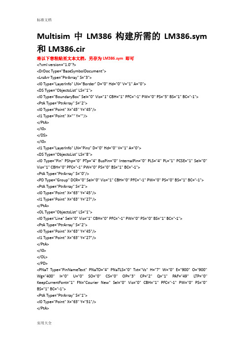
Multisim中LM386构建所需地LM386.sym和LM386.cir
<I1 Type="Point" X="63" Y="27"/>
</PtA>
</I0>
</OL>
</PD>
<PNaT Type="PinNameText" PNaTO="4" PNaTLS="0" Txt="Vs" H="7" W="0" E="900" O="900" Wg="400" I="0" U="0" SO="0" CS="0" OP="3" CP="2" Q="1" PAF="49"LTP="0" KeepCurrentFont="1" FN="Courier New" Sel="0" Vis="0" CBH="1" PFC="-1" PW="0" PS="0" BS="1" BC="-1">
<PtA Type="PtrArray" S="1">
<I0 Type="Point" X="91" Y="41"/>
- 1、下载文档前请自行甄别文档内容的完整性,平台不提供额外的编辑、内容补充、找答案等附加服务。
- 2、"仅部分预览"的文档,不可在线预览部分如存在完整性等问题,可反馈申请退款(可完整预览的文档不适用该条件!)。
- 3、如文档侵犯您的权益,请联系客服反馈,我们会尽快为您处理(人工客服工作时间:9:00-18:30)。
The LM386 is a low voltage audio power amplifier integrated circuit (IC). To be able to simulate the component in Multisim and use it in Ultiboard PCB designs, it needs to be created using the Component Wizard in Multisim. Files needed:
Symbol file (LM386.sym)
and SPICE model (LM386.cir).
Start Multisim. Under "Tools", choose "Component Wizard".
Step 1: Enter component information.
Step 2: Enter footprint information.
Click on "Select a footprint".
如何在multism中新建LM386器件multism中是没有LM386器件的,下面手把手教大家在multism中新建LM386.
此方法由本人在university of colorado boulder(科罗拉多大学波德分校)的ECEE学院网站上找到。
虽然全英文,但比较简单,懒得翻译了。
---oldsun
=>原文地址:/~mathys/ecen1400/Software/CreateLM386.html
注意:新建LM386有两个必需文件:LM386.sym和LM386.cir。
点击pdf中的超链接在浏览器中打开,然后选择“网页另存为”两个文件,然后重命名为LM86.sym和LM386.cir即可。
下面提供备用下载地址:链接: /s/1dDq7qPN 密码: cktc
There are some 5000 footprints in the Master Database. To find the one that we need more easily, click on "Filter". Click on "Add row" and select "Footprint" from the drop down menu under "Column". Set the "Operator" to "Contains" and enter "DIP8" under "Value" as shown below.
Select the "Ultiboard DIP8" footprint.
Click on "Select". In the footprint information window set the number of pins to 8.
Step 3: Enter symbol information.
Click on "Edit" to open the Symbol Editor.
open the LM386.sym file.
Do not change any of the pin information that appears at the bottom of the symbol editor. Click on "Exit" and answer "Yes" to the "Save changes?" question. Now the symbol information window should look like this:
Step 4: Set pin parameters. Click on "Next" and change the pin Types for the different pins (from "BIDIRECTIONAL") to the values shown below.
Step 5: Set mapping information between symbol and layout footprint. Click "Next" and fill in the footprint pins in as shown next.
Step 6: Select simulation model. Click "Next" to obtain the "Select simulation model" window.
Download the file LM386.cir
and remember the location where you put it. Then click on "Load from file" and open the LM386.cir file. You should see a window with the LM386 SPICE model filled in as shown below.
Step 7: Mapping information between symbol and simulation model. Click "Next" and fill in the Model nodes in the Pin mapping table as follows. (Note: The model nodes are numbered 1,2,3,... from left to right in the .SUBCKT specification, irrespective of the pin numbers in the footprint mapping.)
Step 8: Save component to database. Click "Next" and in the next window click on "User Database" and select "Analog".
或者vs
g1g8
out inn inp gnd byp
Click on "Add family" and enter "Amplifier" for the family name.
Finally, click "Finish" and you are done with LM386 component creation. Check that you can select the component in Multisim.
Then place the component on a schematic.
©2008, 2013-2014, P. Mathys. Last revised: 01-29-14, PM.。