ADS设计D触发器
D触发器设计

要求:采用0.25um CMOS工艺(SPICE模型,BSIM3.1)设计一个基于传输门结构的D触发器,要求该D触发器带有异步高电平置位。
1)用HSPICE仿真验证该D触发器功能的正确性。
2)利用HSPICE仿真得出该D触发器的建立时间、保持时间和传输延时的值,假设D触发器的负载是该D触发器的数据输入端。
3)请优化该D触发器的晶体管尺寸,使建立时间最小。
4)优化尺寸使传输延时最小。
仿真过程中,输入信号和clock的跳变沿(上升沿时间和下降沿时间)统一为0.2ns。
如下面的clock的例子:vclk clock 0 pulse (0 2.5 0 0.2n 0.2n 4.8n 10n)建立时间定义含混,难以精确确定。
一般减小寄存器数据到clock的时间不会使输出立刻出错,但它会使输出延时增大,所以一般建立时间的定义有两种方法:(b)1、定义成时钟之前数据输入必须有效的时间。
(但有效的含义是什么,难以精确确定)2、定义成使D-Clk时间差与tc-q延时的和最小时寄存器的工作点。
这一点使触发器的延时总开销最小。
即图(b)中斜率45度的点。
X轴和Y轴等比例!在全定制设计中这个值可以比较接近出错点,但在半定制标准单元设计中,寄存器的建立时间和保持时间定义成相对tcq增大一个固定百分比时(一般为5%),数据-时钟的时间差。
注意,这些曲线在0-1和1-0翻转时不同,因此0和1值得建立时间和保持时间是不一样的,另外建立时间和保持时间还和时钟与数据的斜率有关,在非线性模型中用一个二维表格表示。
在本练习中,采用第二种建立时间定义方法。
假定都采用使输出延时比原来增大5%的时间点作为建立时间。
分别测量输出“1”和输出“0”的不同的建立时间。
保持设计的定义与此相似,,同样用输出延时增加5%作为定标点。
主从D触发器电路图:图1建立时间指信号D在clk上升沿之前必须稳定的时间。
传输延迟指从QM到达Q 的时间;保持时间指信号D在clk上升沿之后必须保持稳定的时间。
数字系统设计d触发器
数字系统设计d触发器
数字系统设计D触发器是数字电路中常用的基本元件之一,它可以将输入信号在时钟上升沿时锁存,输出信号在时钟下降沿时更新。
下面我们来详细了解一下D触发器的相关知识。
1. D触发器的基本结构
D触发器由两个与非门和一个反馈路径组成。
其中,一个与非门的输入端连接时钟信号,另一个与非门的输入端连接D输入信号,输出端连接反馈路径,反馈路径的输出端连接第一个与非门的另一个输入端。
这样,当时钟信号上升沿来临时,D输入信号就会被锁存到反馈路径中,输出端会输出相应的信号。
2. D触发器的应用
D触发器在数字电路中有着广泛的应用,例如,它可以被用来实现计数器、寄存器、状态机等电路。
在计数器中,D触发器可以被用来记录输入脉冲的数量;在寄存器中,D触发器可以被用来存储数据;在状态机中,D触发器可以被用来记录当前状态。
3. D触发器的特点
D触发器有着以下几个特点:
(1)D触发器具有较高的稳定性和可靠性,可以在高速数字电路中使用。
(2)D触发器的输出信号只在时钟下降沿时更新,可以有效地避免由于信号传输延迟而导致的错误。
(3)D触发器的反馈路径可以实现电路的锁存功能,可以在数字电路中实现各种复杂的逻辑运算。
4. D触发器的扩展
D触发器可以通过添加预置和清零功能来扩展其功能。
预置和清零功能可以使D触发器在特定条件下自动将输出信号设置为高电平或低电平,从而实现更加复杂的数字电路设计。
总的来说,数字系统设计D触发器是数字电路中非常重要的基本
元件,它可以实现锁存、计数、存储等多种功能。
了解D触发器的基本结构、应用、特点以及扩展,对于数字电路的设计和实现都有着重要的意义。
抢答器(D触发器方案)

25
26
23
74LS175D VCC 5VΒιβλιοθήκη GND R11 511 GND
14
&
GND
U2A 74LS00D 1 V1 U2B 74LS00D 1MHz 5V GND GND
15
&
三, 电路原理参考图2
VCC VCC R7 511 R8 511 R9 511 R10 511 24 J1 Key = A J3 Key = B 0 27 J4 Key = C J5 Key = D J2 VCC Key = Space 21 22
&
2 LED2 3 LED3 4
25
511
26
23
74LS175D VCC 5V
5
0
SONALERT 200 Hz
14 R11 511
0 U2A 74LS00D
VCC
R1 1.00k 17
16 555_VIRTUAL Timer
OUT
RST DIS THR TRI
15
&
18
R2 1.00k
U2B 74LS00D
CON GND
20 0.1nF C 19 0.47nF Cf
0
�
1 9 4 5 12 13 ~CLR CLK 1D 2D 3D 4D 1Q ~1Q 2Q ~2Q 3Q ~3Q 4Q ~4Q 2 3 7 6 10 11 15 14
LED1 6 R3 511 R4 8 10 12 7 9 11 13 511 LED3 R5 511 LED4 R6 511 U4 0 U3A 74LS20D SONALERT 200 Hz 5 0 4 2 LED2 3
D触发器的设计和仿真报告
实验一、D触发器的设计和仿真一、实验目的1、学习模拟数字电路单元的基本设计方法,其中包括反相器、传输门、与非门。
2、学习Cadence工具下电路设计的基本操作和方法,包括电路图的编辑以及仿真调试过程。
二、实验内容本实验通过设计一个异步清零的D触发器电路学习Cadence工具下电路的设计和仿真方法。
实验内容包括:1.熟悉Cadence界面及基本的建立新的cell文件等基本过程;2.完成反相器、与非门、传输门电路的设计,并进行波形仿真,根据波形验证功能是否实现;3.在此基础上,完成各个单元电路symbol的建立;4.利用建立的单元电路symbol完成D触发器电路的设计和仿真;5.利用Cadence的仿真环境得到波形,分析仿真结果。
该电路设计采用上华CSMC0.5umCMOS工艺设计,工作电压5V。
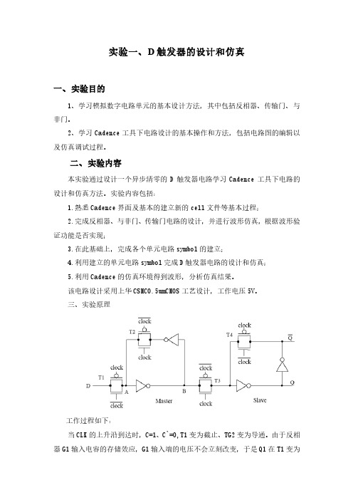
三、实验原理工作过程如下:当CLK的上升沿到达时,C=1、C`=0,T1变为截止、TG2变为导通。
由于反相器G1输入电容的存储效应,G1输入端的电压不会立刻改变,于是Q1在T1变为截止前的状态被保存下来。
同时,随着T4变为截止、T3变为导通,Q1的状态通过T3和G3、G4送到了输出端,使Q*=D(CLK上升沿到达时D的状态)。
因此,这是一个上升沿出发的D触发器。
四、实验步骤1、登陆到UNIX系统。
在登陆界面,输入用户名stu01和密码123456。
2、Cadence的启动。
登录进去之后,点击Terminal出现窗口,输入icfb命令,启动Cadence软件。
3、原理图的输入。
(1)Composer的启动。
在CIW窗口新建一个单元的Schematic视图。
(2)添加器件。
在comparator schematic窗口点击Add-Instance或者直接点i,就可以选择所需的器件。
(3)添加连线。
执行Add-Wire,将需要连接的部分用线连接起来。
(4)添加管脚。
执行Add-Pin和直接点p,弹出添加管脚界面。
D触发器的设计和仿真

D触发器的设计和仿真
D触发器是数字电路中常见的一种触发器,它可以用于存储一位二进
制数据。
设计和仿真一个D触发器需要以下步骤:
1.确定D触发器的功能需求:D触发器具有一个输入端D、一个时钟
端CLK和一个输出端Q。
当CLK上升沿到来时,D触发器会将输入D的值
存储到输出Q中。
2.设计D触发器的逻辑电路:根据D触发器的功能需求,我们可以设
计逻辑电路来实现。
一种常用的实现方式是使用两个锁存器构成的锁存器
电路。
3.实现逻辑电路的布局和布线:根据设计的逻辑电路,将电路图转化
为电路布局和布线图。
这一步需要考虑电路的物理尺寸和电连接的布局。
4.进行仿真:使用电路设计软件,如TINA等,将设计的电路进行仿真。
仿真可以验证电路的功能是否符合设计需求,并找出可能存在的问题。
5.优化电路设计:根据仿真结果,对电路进行优化。
可能需要对电路
的逻辑设计进行调整,或者改进布局和布线方式,以提高电路的性能。
6.进行电路验证:在优化后,再次进行仿真验证,确保电路的功能和
性能满足设计需求。
7.进行实际制作和测试:最后,将电路进行实际制作,并进行测试。
测试可以包括输入输出波形的测量、电路的稳定性测试等等。
总结:设计和仿真一个D触发器是一个大致的流程,通过逐步优化和
测试,可以得到一个满足设计需求的D触发器电路。
在设计和仿真的过程中,需要运用逻辑电路设计原理、电路布局和布线技术,以及仿真工具等。
通过不断的实验和验证,可以不断改进和优化电路设计,以获得更好的设计结果。
D触发器电路设计
D触发器电路设计D触发器是一种数电元件,常用于数字电路中的时序逻辑设计。
它可以在时钟信号的作用下,根据输入信号的变化来产生输出信号,实现数据的存储、传输和逻辑运算等功能。
在本文中,我们将介绍D触发器电路的设计原理、基本结构以及应用方面的注意事项。
D触发器是由两个互为反相的RS触发器级联构成的,其中一个RS触发器的S输入端与R输入端相连,称为主触发器;另一个RS触发器的S 输入端与R输入端也相连,但是与主触发器反相,称为从触发器。
两个触发器的时钟信号需相同。
主触发器的S输入端接受输入信号D,而从触发器的输入信号始终为主触发器的输出信号。
D触发器的逻辑功能如下:-当时钟信号为上升沿(或下降沿)时,D触发器将当前D输入信号的值复制到输出信号上,使其实现数据的存储;-当时钟信号为下降沿(或上升沿)时,D触发器将保持其输出信号的值不变,即保持数据的传输。
在设计D触发器电路时,我们需要考虑以下几个因素:1.时钟信号的频率和稳定性:时钟信号的频率应满足设计需求,并且具有良好的稳定性,以保证触发器能够按照预期的时序进行工作。
2.输入信号的稳定性:输入信号在时钟信号的作用下可能会发生瞬时变化,因此需要确保输入信号在触发器时钟周期内保持稳定,避免出现脉冲噪声。
3.输出信号的延迟和浮动:D触发器的输出信号在时钟信号作用下会有一定的延迟,并且可能存在浮动。
在设计过程中需要对此进行合理的考虑和处理,以保证输出信号的准确性和稳定性。
4.输入信号的滤波和去抖动:为了确保输入信号在时钟信号的作用下的稳定性,可以采用适当的滤波和去抖动技术,使输入信号不受外界噪声的影响。
在实际应用中,D触发器电路常用于存储器、寄存器、计数器等数字电路中,用于实现数据的存储和传输,以及时序逻辑的控制。
在这些应用中,合理设计和使用D触发器电路可以提高数字电路的性能和可靠性。
总之,D触发器电路是一种重要的数字电路元件,其设计原理和应用需要充分考虑时钟信号的稳定性、输入信号的稳定性、输出信号的延迟和浮动等因素。
D触发器教程 图文

1
11 0 0 0
1
11 1 0 0
0
0 0 0
0
1 0 0
1
0 1 1 0 1 1
1
0 不用
注
保持
同步置0
同步置1
翻转
不变
异步置1 异步置0 不允许
2. TTL 边沿 JK 触发器 74LS112 (双 JK 触发器) • CP 下降沿触发 • 异步复位端 RD、异步置位端 SD 均为低电平有效
当 CP = 0 SR1
曾用符号
Qn1 Qn
国标符号
保持
当 CP = 1 SCP S1S RCP R1R
与基本 RS 触发器功能相同
特性表:
特性方程:
CP R S Q n Q n+1 注
Qn1SRQn
0 Q n 保持
RS0 约束条件
1000 1001 1010 1011 1100 1101
0 1,延迟时间为 tPLH 。 由于实际中翻转延迟时间相对于脉
G1 &
&
信信号号同不时同撤时消撤,出
冲的宽度和周期很小,故可视为0。 现消S不,确状定态状确R态定 设触发器初始状态为0:
S
S
R
R
Q
Q
Q
Q
三、现态、次态、特性表和特性方程
1. 现态和次态
现态Qn:触发器接收输入信号之前的状态。
次态Qn+1:触发器接收输入信号之后的新状态。
1R
4
1SA
1Q
1SB 2R
74279
2Q
7
233SRSA74LS2793Q 9
3SB 4R
d触发器参数设计
d触发器参数设计D触发器是一种常用的数字逻辑电路元件,常用于时序电路和存储电路中。
它的工作原理是通过输入信号的上升沿或下降沿触发,改变输出信号的状态。
本文将从D触发器的参数设计角度出发,探讨其在电路设计中的应用。
D触发器的参数设计中最重要的一个参数是时钟信号,也就是触发信号。
时钟信号的频率和占空比直接影响到D触发器的工作性能。
频率过高会导致信号的延迟和抖动问题,频率过低则会影响电路的响应速度。
占空比过大或过小也会导致触发不稳定。
因此,在设计D触发器时,需要根据实际需要选择合适的时钟信号参数,以保证电路的可靠性和稳定性。
除了时钟信号,D触发器的另一个重要参数是输入信号的灵敏度。
在大多数情况下,D触发器是在上升沿或下降沿触发的,但也有一些特殊情况下需要在其他条件下触发。
因此,在设计D触发器时,需要根据实际需求选择合适的灵敏度参数,以确保电路能够按照预期工作。
D触发器的参数设计还涉及到输入和输出电平的阈值。
输入信号的电平阈值决定了触发器对输入信号的识别能力,过高或过低的阈值都可能导致误判。
而输出信号的电平阈值则决定了触发器的输出电平范围,过高或过低的阈值都可能导致输出信号失真。
因此,在设计D触发器时,需要根据实际情况选择合适的阈值参数,以确保电路的可靠性和准确性。
D触发器的参数设计还需要考虑功耗和面积等因素。
功耗是指D触发器在工作过程中所消耗的能量,通常以静态功耗和动态功耗两种形式存在。
静态功耗是指D触发器在保持状态时的功耗,动态功耗是指D触发器在切换状态时的功耗。
面积是指D触发器所占据的芯片面积,通常以平方微米为单位。
因此,在设计D触发器时,需要在功耗和面积之间进行权衡,选择合适的参数,以满足电路的性能和成本要求。
D触发器的参数设计是电路设计中的重要环节。
时钟信号、输入信号灵敏度、输入输出电平阈值、功耗和面积等参数都需要经过仔细的考虑和选择,以确保电路的可靠性、稳定性和性能。
只有在合理设计参数的基础上,D触发器才能发挥出最佳的作用,实现电路设计的目标。
D触发器的设计和仿真
D触发器的设计和仿真D触发器是一种基本的数字电路元件,用于存储和传递数字信号。
它在数字系统中具有重要的作用,可用于时序逻辑电路的设计和实现。
以下是关于D触发器的设计和仿真的详细说明。
设计:D触发器是一种双稳态(两个稳定状态之间切换)存储器件,通常由两个反馈电路组成,即RS(复位-设置)锁存器和时钟。
它有一个输入端(称为D输入),一个输出端(称为Q输出),和一个时钟输入端(CLK)。
D-----Clk---,---, ____________,_D,/----&,\/,__________Y在这个电路中,CLK为时钟输入,D为输入信号,Q为输出信号。
当CLK为高电平时,D的输入信号被存储在Q输出端;当CLK为低电平时,Q 输出端的数值保持不变。
仿真:可以使用电路仿真工具来验证和验证D触发器的设计。
其中最常用和广泛使用的电路仿真工具是Spice(Simulation Program with Integrated Circuit Emphasis)。
在Spice中,可以使用硬件描述语言(HDL)来描述电路的连接和元件属性。
以下是一个基于Spice的D触发器仿真的示例代码:```*D触发器M1QCLKVDD0CMOSPL=1uW=0.5uM2QD0VDDCMOSPL=1uW=0.5uM3DCLKGNDGNDCMOSNL=1uW=0.5uR1QOUT1kV1CLK0DC5VV2 D 0 PULSE 0 5 0 50ns 50ns 20us 40us.tran 0.1ns 100us.end```在这个示例中,M1、M2和M3分别代表CMOSP(pMOS)和CMOSN (nMOS)开关,并使用L和W定义它们的尺寸。
R1是输出端电阻,V1和V2分别是时钟输入端和D输入端的电压源。
通过运行这个Spice仿真文件,可以获得D触发器的输入和输出波形,以验证其功能和性能。
总结:。
D触发器工作原理
D触发器工作原理引言概述:D触发器是数字电路中常用的一种触发器,它具有存储和时序控制的功能。
本文将详细介绍D触发器的工作原理,包括其基本原理、实现方式、时序图和应用场景。
一、D触发器的基本原理:1.1 逻辑门实现:D触发器可以通过逻辑门电路实现。
其中最常用的是与门和非门组成的结构,也可以通过与非门或与或非门等组合实现。
1.2 存储功能:D触发器具有存储功能,它可以存储输入信号的状态,并在时钟信号的作用下保持输出状态不变。
1.3 边沿触发:D触发器可以根据时钟信号的上升沿或下降沿来触发输出状态的变化,分为上升沿触发和下降沿触发两种类型。
二、D触发器的实现方式:2.1 RS触发器:D触发器可以通过RS触发器实现。
RS触发器由两个交叉连接的与非门组成,其中一个与非门的输出连接到另一个与非门的输入,另一个与非门的输出连接到第一个与非门的输入。
2.2 JK触发器:D触发器也可以通过JK触发器实现。
JK触发器由两个交叉连接的与非门和一个与门组成,其中一个与非门的输出连接到与门的输入,另一个与非门的输出连接到另一个与非门的输入。
2.3 T触发器:D触发器还可以通过T触发器实现。
T触发器由两个交叉连接的与非门和一个异或门组成,其中一个与非门的输出连接到异或门的一个输入,另一个与非门的输出连接到异或门的另一个输入。
三、D触发器的时序图:3.1 上升沿触发时序图:D触发器在时钟信号的上升沿触发时,输入信号的状态将在上升沿之前保持不变,并在上升沿之后更新到输出。
3.2 下降沿触发时序图:D触发器在时钟信号的下降沿触发时,输入信号的状态将在下降沿之前保持不变,并在下降沿之后更新到输出。
3.3 延迟时间:D触发器的输出状态更新存在一定的延迟时间,这取决于时钟信号的频率和触发器的特性。
四、D触发器的应用场景:4.1 时序电路:D触发器在时序电路中广泛应用,可以实现各种时序逻辑功能,如计数器、寄存器等。
4.2 控制电路:D触发器可以用于控制电路中,实现状态的存储和控制信号的生成。
D触发器电路设计

D触发器电路设计D触发器是数字电路中常用的一种时序电路。
它的主要功能是在特定的时钟脉冲到来时,根据D输入的电平状态,将其传递到输出端。
D触发器的电路设计包含以下几个关键步骤:1.确定逻辑电路的功能需求。
首先,需要明确D触发器的功能需求,例如,是边沿触发还是电平触发,是正逻辑还是负逻辑,以及输入输出的逻辑电平等。
2.根据功能需求选择适当的D触发器类型。
常用的D触发器类型有SR触发器、JK触发器和D触发器。
根据实际需求选择适当的D触发器类型。
3.分析电路逻辑。
根据D触发器的功能需求,分析电路逻辑,确定逻辑门的连接方式和输入输出的电平关系。
可以使用真值表或逻辑方程来描述和分析电路逻辑。
4.确定时钟脉冲的输入方式。
D触发器的输入与输出之间是通过时钟信号来控制的。
需要确定时钟脉冲的输入方式,可以是外部输入的时钟信号,也可以是内部产生的时钟信号。
5.绘制电路图。
根据上述分析结果,绘制D触发器的逻辑电路图。
使用逻辑门符号和连接线将逻辑电路图绘制出来。
6.确定元器件参数。
根据电路图,确定所需元器件的参数,例如,逻辑门的输入电压范围、输出电流能力等。
7.进行仿真和验证。
利用电路设计软件进行仿真,验证所绘制的电路图是否符合设计要求。
可以通过添加合适的输入信号,观察输出信号是否符合预期。
8.选择合适的元器件进行实际电路实现。
根据元器件参数和设计要求,选择合适的元器件进行实际的电路实现。
9.进行电路测试和调试。
对实际实现的电路进行测试和调试,观察输入输出的电平是否符合设计要求,并对电路进行必要的调整和优化。
10.完善设计文档。
记录电路设计的过程和结果,包括电路图、元器件清单、仿真结果、测试结果等,以便于后续的参考和修改。
以上是D触发器电路设计的主要步骤。
在实际设计中,还需要考虑功耗、抗干扰性能、电路布局等因素,并针对具体的应用场景进行相应的设计优化。
同时,还可以结合其他的功能模块和电路设计技巧,设计出更加复杂和功能强大的数字电路。
D触发器原理-D触发器电路图
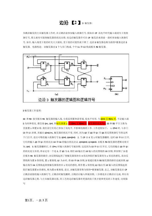
边沿【2 】D 触发器:负跳沿触发的主从触发器工作时,在正跳沿前参加输入旌旗灯号.假如在CP 高电平时代输入端消失干扰旌旗灯号,那么就有可能使触发器的状况出错.而边沿触发器许可在CP 触发沿来到前一刹时参加输入旌旗灯号.如许,输入端受干扰的时光大大缩短,受干扰的可能性就下降了.边沿D触发器也称为保持-壅塞边沿D触发器. 电路构造: 该触发器由6个与非门构成,个中G1和G2构成根本RS触发器.D触发器工作道理:SD 和RD 接至根本RS 触发器的输入端,分离是预置和清零端,低电平有用.当SD=0且RD=1时,不论输入端D为何种状况,都邑使Q=1,Q=0,即触发器置1;当SD=1且RD=0时,触发器的状况为0,SD和RD平日又称为直接置1和置0端.我们设它们均已参加了高电平,不影响电路的工作.工作进程如下: 1.CP=0时,与非门G3和G4封锁,其输出Q3=Q4=1,触发器的状况不变.同时,因为Q3至Q5和Q4至Q6的反馈旌旗灯号将这两个门打开,是以可吸收输入旌旗灯号D,Q5=D,Q6=Q5=D. 2.当CP由0变1时触发器翻转.这时G3和G4打开,它们的输入Q3和Q4的状况由G5和G6的输出状况决议.Q3=Q5=D,Q4=Q6=D.由根本RS触发器的逻辑功效可知,Q=D. 3.触发器翻转后,在CP=1时输入旌旗灯号被封锁.这是因为G3和G4打开后,它们的输出Q3和Q4的状况是互补的,即必定有一个是0,若Q3为0,则经G3输出至G5输入的反馈线将G5封锁,即封锁了D通往根本RS 触发器的路径;该反馈线起到了使触发器保持在0状况和阻拦触发器变为1状况的感化,故该反馈线称为置0保持线,置1壅塞线.Q4为0时,将G3和G6封锁,D端通往根本RS触发器的路径也被封锁.Q4输出端至G6反馈线起到使触发器保持在1状况的感化,称作置1保持线;Q4输出至G3输入的反馈线起到阻拦触发器置0的感化,称为置0壅塞线.是以,该触发器常称为保持-壅塞触发器.总之,该触发器是在CP正跳沿前接收输入旌旗灯号,正跳沿时触发翻转,正跳沿后输入即被封锁,三步都是在正跳沿后完成,所以有边沿触发器之称.与主从触发器比拟,同工艺的边沿触发器有更强的抗干扰才能和更高的工作速度.功效描写2.特点方程 Qn+1=D3状况转移图脉冲特点: 1.树立时光:由下图保持壅塞触发器的电路可见,CP旌旗灯号是加到门G3和G4上的,因而在CP 上升沿到达之前门G5和G6输出端的状况必须稳固地树立起来.输入旌旗灯号到达D端今后,要经由一级门电路的传输延迟时光G5的输出状况才能树立起来,而G6的输出状况须要经由两级门电路的传输延迟时光才能树立,是以D端的输入旌旗灯号必须先于CP的上升沿到达,并且树立时光应知足: tset≥2tpd. 2.保持时光:由下图可知,为实现边沿触发,应保证CP=1时代门G6的输出状况不变,不受D端状况变化的影响.为此,在D=0的情形下,当CP上升沿到达今后还要等门G4输出的低电平返回到门G6的输入端今后,D端的低电平才许可转变.是以输入低电平旌旗灯号的保持时光为tHL≥tpd.在 D=1的情形下,因为CP上升沿到达后G3的输出将G4封锁,所以不请求输入旌旗灯号中断保持不变,故输入高电平旌旗灯号的保持时光tHH=0. 3.传输延迟时光:由图工作波形图不难推算出,从CP上升沿到达时开端盘算,输出由高电平变为低电平的传输延迟时光tPHL和由低电平变为高电平的传输延迟时光tPLH分离是:tPHL=3tpd tPLH=2tpd保持和壅塞D触发器的电路和动态波形4.最高时钟频率:为保证由门G1~G4构成的同步RS触发器能靠得住地翻转,CP高电平的中断时光应大于tPHL,时钟旌旗灯号高电平的宽度tWH应大于tPHL.而为了鄙人一个CP上升沿到达之前确保门G5和G6新的输出电平得以稳固地树立,CP低电平的中断时光不应小于门G4的传输延迟时光和tset之和,即时钟旌旗灯号低电平的宽度tWL≥tset+tpd,是以得到:在现实集成触发器中,每个门传输时光是不同的,并且作了不同情势的简化,是以上面评论辩论的成果只是一些定性的物理概念.其真实参数由试验测定. 综上所述,对边沿D触发器归纳为以下几点: 1.边沿D触发器具有吸收并记忆旌旗灯号的功效,又称为锁存器;2.边沿D触发器属于脉冲触发方法;3.边沿D触发器不消失束缚前提和一次变化现象,抗干扰机能好,工作速度快。
D触发器原理-D触发器电路图

边沿D 触发器:负跳沿触发的主从触发器工作时,在正跳沿前加入输入信号。
如果在CP 高电平期间输入端出现干扰信号,那么就有可能使触发器的状态出错。
而边沿触发器允许在CP 触发沿来到前一瞬间加入输入信号。
这样,输入端受干扰的时间大大缩短,受干扰的可能性就降低了。
边沿D触发器也称为维持-阻塞边沿D触发器。
电路结构: 该触发器由6个与非门组成,其中G1和G2构成基本RS触发器。
D触发器工作原理:SD 和RD 接至基本RS 触发器的输入端,分别是预置和清零端,低电平有效。
当SD=0且RD=1时,不论输入端D为何种状态,都会使Q=1,Q=0,即触发器置1;当SD=1且RD=0时,触发器的状态为0,SD和RD通常又称为直接置1和置0端。
我们设它们均已加入了高电平,不影响电路的工作。
工作过程如下:1.CP=0时,与非门G3和G4封锁,其输出Q3=Q4=1,触发器的状态不变。
同时,由于Q3至Q5和Q4至Q6的反馈信号将这两个门打开,因此可接收输入信号D,Q5=D,Q6=Q5=D。
2.当CP由0变1时触发器翻转。
这时G3和G4打开,它们的输入Q3和Q4的状态由G5和G6的输出状态决定。
Q3=Q5=D,Q4=Q6=D。
由基本RS触发器的逻辑功能可知,Q=D。
3.触发器翻转后,在CP=1时输入信号被封锁。
这是因为G3和G4打开后,它们的输出Q3和Q4的状态是互补的,即必定有一个是0,若Q3为0,则经G3输出至G5输入的反馈线将G5封锁,即封锁了D通往基本RS 触发器的路径;该反馈线起到了使触发器维持在0状态和阻止触发器变为1状态的作用,故该反馈线称为置0维持线,置1阻塞线。
Q4为0时,将G3和G6封锁,D端通往基本RS触发器的路径也被封锁。
Q4输出端至G6反馈线起到使触发器维持在1状态的作用,称作置1维持线;Q4输出至G3输入的反馈线起到阻止触发器置0的作用,称为置0阻塞线。
因此,该触发器常称为维持-阻塞触发器。
总之,该触发器是在CP正跳沿前接受输入信号,正跳沿时触发翻转,正跳沿后输入即被封锁,三步都是在正跳沿后完成,所以有边沿触发器之称。
D触发器电路设计

D触发器电路设计D触发器是数字电路中常用的一种触发器。
它采用两个互补反相的输入信号,根据输入信号的状态变化来改变输出信号的状态。
本文将详细介绍D触发器电路的设计过程。
首先,我们需要确定D触发器的功能需求和工作频率。
D触发器的功能是根据D输入信号的状态(高电平或低电平)来决定输出信号的状态(保持或反转)。
工作频率是指触发器每秒处理的信号个数,通常以赫兹(Hz)表示。
接下来,我们需要选择合适的逻辑门作为D触发器的基本构建模块。
常见的逻辑门有与门(AND)、或门(OR)、非门(NOT)和异或门(XOR)等。
根据功能需求,我们可以选择不同的逻辑门来实现D触发器。
以D触发器的最简单形式,RS触发器为例,其实现方式如下:1.使用两个非门构成RS触发器的RS(重置和置位)输入端。
2.将D输入信号连接到RS触发器的S(置位)输入端。
3.将D输入信号取反连接到RS触发器的R(重置)输入端。
RS触发器的真值表如下:```D,R,S,Q(t),Q(t+1)---------------------------------0,0,1,0,00,1,0,0,11,0,0,1,01,1,1,x,x```其中,Q(t)表示触发器当前状态,Q(t+1)表示触发器下一个状态。
x 表示无效状态。
接下来,我们需要根据RS触发器的实现方式进行电路设计。
设计过程包括电路连接方式、逻辑门选择和信号线路布局等。
1.连接方式:根据RS触发器的实现方式,将D输入信号连接到RS触发器的S(置位)输入端,并将D输入信号取反连接到RS触发器的R(重置)输入端。
2.逻辑门选择:根据RS触发器的实现方式,使用两个非门作为RS触发器的RS输入端。
非门的输入端分别连接到D输入信号和D输入信号的反相信号。
3.信号线路布局:根据电路图设计合理的信号线路布局,保证信号传输的稳定性和可靠性。
可以使用导线或者线缆来连接逻辑门和触发器。
最后,我们需要进行电路测试和优化。
D触发器工作原理

D触发器工作原理D触发器是数字电路中常用的一种触发器,用于存储和传输数字信号。
它由两个互补反相的输出端和一个输入端组成。
D触发器的工作原理是根据输入信号的变化来改变输出信号的状态。
D触发器有两种常见的类型:D型正沿触发器和D型负沿触发器。
这两种类型的触发器在输入信号的边沿上触发输出信号的变化。
D型正沿触发器在输入信号的上升沿触发输出信号的变化,而D型负沿触发器在输入信号的下降沿触发输出信号的变化。
D触发器的工作原理可以简单描述如下:1. D触发器的输入端被连接到输入信号源,该信号源可以是一个逻辑门、一个计数器或者其他数字电路的输出端。
2. 当输入信号发生变化时,D触发器会根据触发器的类型,在输入信号的边沿上触发输出信号的变化。
3. 当输入信号发生变化时,D触发器的输出端会根据触发器的类型和输入信号的变化,改变其输出状态。
4. D触发器的输出状态可以保持不变,直到下一个输入信号的边沿触发输出信号的变化。
D触发器的工作原理可以通过以下示意图来说明:```_______D ----| || D |----- QCLK ---| 触 || 发 |----- Q'| 器 ||_______|```在上述示意图中,D表示输入信号,CLK表示时钟信号,Q表示输出信号,Q'表示输出信号的补码。
D触发器的工作原理可以进一步解释如下:- 当时钟信号CLK的边沿触发D触发器时,如果D触发器为D型正沿触发器,则在CLK的上升沿时,D触发器会将输入信号D的值传递到输出信号Q上,并将Q'的值设置为Q的补码。
- 当时钟信号CLK的边沿触发D触发器时,如果D触发器为D型负沿触发器,则在CLK的下降沿时,D触发器会将输入信号D的值传递到输出信号Q上,并将Q'的值设置为Q的补码。
D触发器的工作原理使得它在数字电路中具有重要的应用。
例如,D触发器可以用于存储和传输数据,实现计数器和寄存器等功能。
此外,D触发器还可以用于时序电路中,用于控制和同步数字信号的传输和处理。
上升沿触发的D触发器的设计
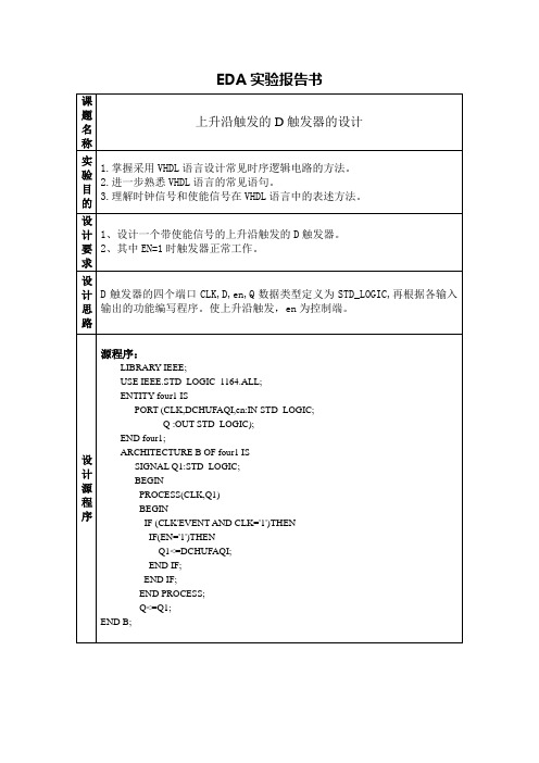
BEGIN
PROCESS(clk,q1)
BEGIN
IF (clk'EVENT AND clk='1')THEN
IF(en='1')THEN
THEN q*<=(j and notq)or(notk and q)
END IF;
END IF;
END PROCESS;
q<=q1;
END ARCHITECTURE bhv;
教师评分
操作成绩
报告成绩
教师签名
日期
SIGNAL Q1:STD_LOGIC;
BEGINPROCLeabharlann SS(CLK,Q1)BEGIN
IF (CLK'EVENT AND CLK='1')THEN
IF(EN='1')THEN
Q1<=DCHUFAQI;
END IF;
END IF;
END PROCESS;
Q<=Q1;
END B;
仿真波形图
实验结果
问题讨论
EDA实验报告书
课题名称
上升沿触发的D触发器的设计
实验目的
1.掌握采用VHDL语言设计常见时序逻辑电路的方法。
2.进一步熟悉VHDL语言的常见语句。
3.理解时钟信号和使能信号在VHDL语言中的表述方法。
设计要求
1、设计一个带使能信号的上升沿触发的D触发器。
2、其中EN=1时触发器正常工作。
设计思路
D触发器的四个端口CLK,D,en,Q数据类型定义为STD_LOGIC,再根据各输入输出的功能编写程序。使上升沿触发,en为控制端。
- 1、下载文档前请自行甄别文档内容的完整性,平台不提供额外的编辑、内容补充、找答案等附加服务。
- 2、"仅部分预览"的文档,不可在线预览部分如存在完整性等问题,可反馈申请退款(可完整预览的文档不适用该条件!)。
- 3、如文档侵犯您的权益,请联系客服反馈,我们会尽快为您处理(人工客服工作时间:9:00-18:30)。
Sheet 1 of 7D-Type flip-flop (Toggle switch) The D-type flip-flops are used in prescalar/divider circuits and frequency phase detectors. Figure 1 shows how the flip-flop (latch) can be made using 2-input logic circuits and Figure 2 shows the input and output waveforms The enable pin needs to be high for data to be fed to the outputs Q and Q bar. The output will only change on the falling edge or trailing edge of the applied clk input.DNANDNANDQEnableNANDQNANDNOTLatchFigure 1 Simple D-type Flip-flop circuit The D type flip-flop has only one input (D for Data) apart from the clock. The INDETERMINATE state is avoided with this flip-flop. When the clock goes high, D (a 0 or a 1) is transferred to Q. When the clock goes low, Q remains unchanged. Q stores the data until the clock goes high again, when new data may be available.Figure 2 Output waveforms of the D-type flip-flop. In this circuit the Q output changes state on the leading edge of the clock.Sheet 2 of 7At A, clock and data are high. Q goes high and stays high until B. At B, clock is high and data is low. Q goes low and stays low until C. At C, clock and data are both high. Q goes high and stays high until E. Q does not change during clock pulse D, because clock and data are still both high. At E, data is low, so Q goes low. At F, data is high so Q goes high. As with the other flip-flop circuits the operation can be improved to eliminate indeterminate states by adding a master latch. The circuit of the master-slave D-type flip-flop is shown in the ADS simulation setup shown in Figure 3. The inverter connected between the two CLK inputs ensures that the two sections will be enabled during opposite half-cycles of the clock signal. Each logic gate is made up of CMOS FETS (based on the 0.8um process) as described in the other tutorials on individual gates.Sheet 3 of 7DTDVtPulseDT SRC4 Vlow=0 V Vhigh=5 V Delay=25 usec Width=50 usec Period=100 usec Rout=1 OhmDTClkVtPulseDT SRC2 Vlow=0 V Vhigh=5 V Delay=0 nsec Width=10 usec Period=20 usec Rout=1 OhmVV_DC SRC1 Vdc=5.0 VVDVcc ANANDVVOUTAVccNANDVVccOUTAVccNANDANANDBbufferedOUTBbufferedOUTBQbufferedPort D Num=1BbufferedNAND_buffered X8NAND_buffered X7VA VccNANDANAND_buffered X2NAND_buffered X4Port Q Num=3VVcc ANANDVVccNANDVVcc ANANDOUTOUTOUTBBQ_barbufferedOUTBbufferedbufferedClkBbufferedPort Clk Num=1NAND_buffered X9Vcc INNAND_buffered X6NAND_buffered X3NAND_buffered X5Port Q_bar Num=4VOUTTRANSIENTTran Tran1 StopTime=150 usec MaxTimeStep=250NOTNOT X10Figure 3 ADS simulation setup of the master-slave D-type flip-flop circuit. In this simaulation there are two square wave generators, the clock at 50KHz and the data (with a 25us delay) running at 10KHz. The simulation is a time-domain transient.Sheet 4 of 7The resulting simulation of the circuit shown in Figure 3 is shown in Figure 4.D-type Flip-flop transitions occur on the falling of the Clk input6 5 4Clk ,V3 2 1 0 -1020406080100120140160time, usec6 5 4D, V3 2 1 0 -1020406080100120140160time, usec6 5 4Q, V3 2 1 0 -1020406080100120140160time, usecFigure 4 Simulation of the Master-slave D-type flip-flop. Note that the transitions occur on the falling edge of the applied clock signal+1/2 half clock cycle due to the slave action.Sheet 5 of 7The D-type flip-flop can be configured as a T-type or Toggle flip-flop. With this configuration the Q_bar output is connected to the D input and the signal/clock is connected to the clk input. The output of this flip-flop will have a frequency half that of the input. The ADS simulation of Figure 6 is shown below (Figure 5)D-type Flip-flop transitions occur on the falling of the Clk input. This D-type is configured as a T-type toggle flip-flop6 5 4Clk ,V3 2 1 0 -1 0 6 5 4 20 40 60 80 100 120 140 160time, usecQ, V3 2 1 0 -1 0 20 40 60 80 100 120 140 160time, usecFigure 5 Simulation results of the D-type flip-flop configured as a T-type (Toggle) flipflop by connecting the D input to the Q_bar output. Such circuits are common in frequency prescalar circuits.Sheet 6 of 7VVcc A NAND BbufferedV VVcc OUT A NAND BbufferedVcc A NAND B OUTbufferedVVcc OUT A NAND BbufferedOUTQ Port Q Num=3NAND_buffered X8NAND_buffered X7 VVcc A NAND OUT B ANAND_buffered X2NAND_buffered X4 VVcc A NAND OUTVVcc A NAND OUTVVcc NANDbufferedOUTBbufferedBbufferedClkBbufferedPort Clk Num=1 V V_DC SRC1 Vdc=5.0 VNAND_buffered X9Vcc INNAND_buffered X6 VNAND_buffered X3NAND_buffered X5TRANSIENTOUT NOTNOT X10Tran Tran1 StopTime=150 usec MaxTimeStep=250 nsecDTVtPulseDT SRC2 Vlow=0 V Vhigh=5 V Delay=0 nsec Width=10 usec Period=20 usec Rout=1 OhmClkFigure 6 Transient ADS simulation of a D-type Flip-Flop configured as a T-type flip-flop by connecting the D input to the Q_bar output.Sheet 7 of 7RF Application Phase detectors are part of a Phase Locked Loop (PLL) and can be either analogue eg mixer or digital eg D-type flip-flop. When a mixer is used the output consists of the sum and difference frequencies. In an analogue mixer a number of different frequencies are generated within the mixer namely the sum of the frequencies and the difference frequency (otherwise known as the beatnote) when both input frequencies are the same is the phase difference is zero and the beatnote is DC. Most PLL circuits now use digital phase detectors formed from two D-type flip-flops as shown in Figure 7.VhighD D type Flip-Flop Q1 Q1F1ClkClear VhighNANDD D type Flip-Flop Q2 Q2F2ClkFigure 7 D-type flip-flop application - Phase frequency phase detector。
