变电站过电压防护毕业论文外文文献翻译及原文
变电站外文翻译外文文献英文文献变电站的综合概述(工程科技)
附录Ⅲ英文翻译A comprehensive overview of substationsAlong with the economic development and the modern industry developments of quick rising, the design of the power supply system become more and more completely and system. Because the quickly increase electricity of factories, it also increases seriously to the dependable index of the economic condition, power supply in quantity. Therefore they need the higher and more perfect request to the power supply. Whether Design reasonable, not only affect directly the base investment and circulate the expenses with have the metal depletion in colour metal, but also will reflect the dependable in power supply and the safe in many facts. In a word, it is close with the economic performance and the safety of the people. The substation is an importance part of the electric power system, it is consisted of the electric appliances equipments and the Transmission and the Distribution. It obtains the electric power from the electric power system, through its function of transformation and assign, transport and safety. Then transport the power to every place with safe, dependable, and economical. As an important part of power’s transport and control, the transformer substation must change the mode of the traditional design and control, then can adapt to the modern electric power system, the development of modern industry and the of trend of the society life.Electric power industry is one of the foundations of national industry and national economic development to industry, it is a coal, oil, natural gas, hydropower, nuclear power, wind power and other energy conversion into electrical energy of the secondary energy industry, it for the other departments of the national economy fast and stable development of the provision of adequate power, and its level of development is a reflection of the country's economic development an important indicator of the level. As the power in the industry and the importance of the national economy, electricity transmission and distribution of electric energy used in these areas is an indispensable component.。
变电站建设外文文献翻译
变电站建设外文文献翻译变电站建设外文文献翻译(文档含中英文对照即英文原文和中文翻译)General Requirements to Construction of SubstationSubstations are a vital element in a power supply system of industrial enterprises.They serve to receive ,convert and distribute electric energy .Depending on power and purpose ,the substations are divided into central distribution substations for a voltage of 110-500kV;main step-down substations for110-220/6-10-35kV;deep entrance substations for 110-330/6-10Kv;distribution substations for 6-10Kv;shop transformer substations for 6-10/0.38-0.66kV.At the main step-down substations, the energy received from the power source is transformed from 110-220kV usually to 6-10kV(sometimes 35kV) which is distributed among substations of the enterprise and is fed to high-voltage services.Central distribution substations receive energy from power systems and distribute it (without or with partial transformation) via aerial and cable lines of deep entrances at a voltage of 110-220kV over the enterprise territory .Central distribution substation differs from the main distribution substation in a higher power and in that bulk of its power is at a voltage of 110-220kV;it features simplified switching circuits at primary voltage; it is fed from the power to an individual object or region .Low-and medium-power shop substations transform energy from 6-10kV to a secondary voltage of 380/220 or 660/380.Step-up transformer substations are used at power plants for transformation of energy produced by the generators to a higher voltage which decreases losses at a long-distancetransmission .Converter substations are intended to convert AC to DC (sometimes vice versa) and to convert energy of one frequency to another .Converter substations with semiconductor rectifiers are convert energy of one frequency to another .Converter substations with semiconductor rectifiers are most economic. Distribution substations for 6-10kV are fed primarily from main distribution substations (sometimes from central distribution substations).With a system of dividing substations for 110-220kV, the functions of a switch-gear are accomplished by switch-gears for 6-10kV at deep entrance substations.Depending on location of substations their switch-gear may be outdoor or indoor. The feed and output lines at 6-10kV substations are mainly of the cable type .at 35-220kV substations of the aerial type .When erecting and wiring thesubstations ,major attention is given to reliable and economic power supply of a given production.Substations are erected by industrial methods with the use of large blocks and assemblies prepared at the site shops of electric engineering organizations and factories of electrical engineering industry .Substations are usually designed for operation without continuous attendance of the duty personnel but with the use of elementary automatic and signaling devices.When constructing the structural part of a substation .it is advisable to use light-weight industrial structures and elements (panels ,floors ,etc.) made of bent sections .These elements are pre-made outside the erection zone and are only assembled at site .This considerably cuts the terms and cost of construction.Basic circuitry concepts of substations are chosen when designing a powersupply system of the enterprise .Substationsfeature primary voltage entrances .transformers and output cable lines or current conductors of secondary voltage .Substations are mounted from equipment and elements described below .The number of possible combinations of equipment and elements is very great .Whenelaborating a substation circuitry ,it is necessary to strive for maximum simplification and minimizing the number of switching devices .Such substations are more reliable and economic .Circuitry is simplified by using automatic reclosure or automatic change over to reserve facility which allows rapid and faultless redundancy of individual elements and using equipment.When designing transformer substations of industrial enterprises for all voltages ,the following basic considerations are taken into account:1. Preferable employment of a single-bus system with using two-bus systems only to ensure a reliable and economic power supply;2. Wide use of unitized constructions and busless substations;3.Substantiated employment of automatics and telemetry ;if the substation design does not envisage the use of automatics or telemetry ,the circuitry is so arranged as to allow for adding such equipment in future without excessive investments and re-work./doc/554c0a220622192e453610661ed9ad5 1f01d5431.html e of simple and cheap devices-isolating switches ,short-circuiting switches ,load-breaking isolators ,fuses ,with due regard for their switching capacity may drastically cut the need for expensive and critical oil ,vacuum ,solenoid and air switches .Substation and switch-gear circuitries are so made that using the equipment of eachproduction line is fed from individual transformers ,assemblies ,the lines to allow their disconnection simultaneously with mechanisms without disrupting operation of adjacent production flows.When elaborating circuitry of a substation, the most vital task is to properly choose and arrange switching devices(switches ,isolators ,current limiters ,arresters ,high-voltage fuses).The decision depends on the purpose ,power and significance of the substation.Many years ago, scientists had very vague ideas about electricity. Many of them thought of it as a sort of fluid that flowed through wires as water flows through pipes, but they could not understand what made it flow. Many of them felt that electricity was made up of tiny particles of some kind ,but trying to separate electricity intoindividual particles baffled them.Then, the great American scientist Millikan, in 1909,astounded the scientific world by actually weighing a single particle of electricity and calculating its electric charge. This was probably one of the most delicate weighing jobs ever done by man,for a single electric particle weighs only about half of a millionth of a pound. To make up a pound it would take more of those particles than there are drops of water in the Atlantic Ocean.They are no strangers to us, these electric particles, for we know them as electrons. When large numbers of electrons break away from their atoms and move through a wire,we describe this action by saying that electricity is flowing through the wire.Yes,the electrical fluid that early scientists talked about is nothing more than electrical flowing along a wire.But how can individual electrons be made to break awayfrom atoms? And how can these free electrons be made to along a wire? The answer to the first question lies in the structure of the atoms themselves. Some atoms are so constructed that they lose electrons easily. An atom of copper, for example ,is continually losing an electron, regaining it(or another electron),and losing it again. A copper atom normally has 29 electrons, arranged in four different orbits about its nucleus. The inside orbit has 2 electrons. The next larger orbit has 8.The third orbit is packed with 18 electrons . And the outside orbit has only one electron.It is this outside electron that the copper atom is continually losing, for it is not very closely tied to the atom. It wanders off, is replaced by another free-roving electron, and then this second electron also wandersaway.Consequently,in a copper wire free electrons are floating around in all directions among the copper atoms.Thus, even through the copper wire looks quite motionless to your ordinary eye, there is a great deal of activity going on inside it. If the wire were carrying electricity to an electric light or to some other electrical device, the electrons would not be moving around at random. Instead, many of them would be rushing in the same direction-from one end of the wire to the other.This brings us to the second question .How can free electrons be made to move along a wire? Well ,men have found several ways to do that .One way is chemical. V olta,s voltaic pile,or battery, is a chemical device that makes electricity(or electrons)flow in wires. Another way is magnetic. Faraday and Henry discovered how magnets could be used to make electricity flow in a wire.MagnetsAlmost everyone has seen horseshoe magnets-so called because they are shaped like horseshoes. Probably you have experimented with a magnet, and noticed how it will pick up tacks and nails, or other small iron objects. Men have known about magnets for thousands of years.Several thousand years ago, according to legend, a shepherd named Magnes lived on the island of Crete, in the Mediterranean Sea .He had a shepherds crook tipped with iron. One day he found an oddly shaped black stone that stuck to this iron /doc/554c0a220622192e453610661ed9ad51f0 1d5431.html ter, when many other such stones were found, they were called magnets(after Magnets).These were natural magnets.In recent times men have learned how to make magnets out of iron. More important still, they have discovered how to use magnets to push electrons through wires-that is, how to make electricity flow. Before we discuss this, there arecertain characteristics of magnets that we should know about.If a piece of glass is laid on top of a horse- shoes magnet, and if iron filings are then sprink ledon the glass, the filings will arrange themselves into lines. If this same thing is trid with a bar magnet(a horseshoe magnet straightened out),the lines can be seen more easily. These experiments demonstrate what scientists call magnetic lines of force. Magnets, they explain, work through lines of force that ext- end between the two ends of the magnet. But electrons seem to have magnetic lines of force around them, too.This can be proved by sticking a wire through a piece ofcard board, sprinkling iron filings on the cardboard, and connecting a battery to the wire. The filings will tend to form rings around the wire,as a result of the magnetism of the moving electrons(or electricity).So we can see that there is arelationship betweenmoving electrons and magnetism, Magnetism results from the movement of electrons.Of course, electrons are not really flowing in the bar magnet, but they are in motion, circling the nuclei of the iron atoms. However, in the magnet, circling thelined up in such a way that their electrons are circling in the same direction. Perhaps a good comparison might be a great number of boys whirling balls onstrings in a clockwise direction around their heads.翻译:变电站建设的一般要求变电站(所)在电源系统的工业企业是一个至关重要的因素。
供电毕设(含外文文献+中文翻译)

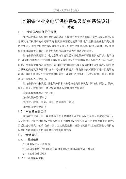
某钢铁企业变电所保护系统及防护系统设计1 绪论1.1 变电站继电保护的发展变电站是电力系统的重要组成部分,它直接影响整个电力系统的安全与经济运行,失恋系发电厂和用户的中间环节,起着变换和分配电能的作用,电气主接线是发电厂变电所的主要环节,电气主接线的拟定直接关系着全厂电气设备的选择、配电装置的布置、继电保护和自动装置的确定,是变电站电气部分投资大小的决定性因素。
继电保护的发展现状,电力系统的飞速发展对继电保护不断提出新的要求,电子技术、计算机技术与通信技术的飞速发展又为继电保护技术的发展不断地注入了新的活力,因此,继电保护技术得天独厚,在40余年的时间里完成了发展的4个历史阶段。
随着电力系统的高速发展和计算机技术、通信技术的进步,继电保护技术面临着进一步发展的趋势。
国内外继电保护技术发展的趋势为:计算机化,网络化,保护、控制、测量、数据通信一体化和人工智能化。
继电保护的未来发展,继电保护技术未来趋势是向计算机化,网络化,智能化,保护、控制、测量、数据通信一体化发展。
微机保护技术的发展趋势:①高速数据处理芯片的应用②微机保护的网络化③保护、控制、测量、信号、数据通信一体化④继电保护的智能化1.2本文的主要工作在本次毕业设计中,我主要做了关于某钢铁企业变电所保护系统及防护系统设计,充分利用自己所学的知识,严格按照任务书的要求,围绕所要设计的主接线图的可靠性,灵活性进行研究,包括:负荷计算、主接线的选择、短路电流计算,主变压器继电保护的配置以及线路继电保护的计算与校验的研究等等。
1.3 设计概述1.3.1 设计依据1)继电保护设计任务书。
2)国标GB50062-92《电力装置的继电保护和自动装置设计规范》3)《工业企业供电》1.3.2 设计原始资料本企业共有12个车间,承担各附属厂的设备、变压器修理和制造任务。
1、各车间用电设备情况用电设备明细见表1.1所示。
表1.1 用电设备明细表2、负荷性质本厂大部分车间为一班制,少数车间为两班或者三班制,年最大有功负荷利用小时数为h2300。
电气工程及其自动化毕业设计外文翻译-一种特殊的预防电压波动的保护方案说明
原文:A SPECIAL PROTECTION SCHEME FOR VOLTAGE STABILITYPREVENTIONTara Alzahawi Student Member, IEEE Mohindar S. Sachdev Life Fellow, IEEEG. Ramakrishna Member, IEEEPower System Research Group University of Saskatchewan Saskatoon, SK S7N5A9, CanadaAbstractVoltage instability is closely related to the maximum load-ability of a transmission network. The energy flows on the transmission system depend on the network topology, generation and loads, and on the availability of sources that can generate reactive power. One of the methods used for this purpose is the Voltage Instability Predictor (VIP). This relay measures voltages at a substation bus and currents in the circuit connected to the bus. From these measurements, it estimates the Thévenin’s equivalent of the network feeding the substation and the impedance of the load being supplied from the substation. This paper describes an extension to the VIP technique in which measurements from adjoining system buses and anticipated change of load are taken into consideration as well.Keywords: Maximum load ability; Voltage instability; VIP algorithm.1.IntroductionDeregulation has forced electric utilities to make better use of the available transmission facilities of their power system. This has resulted in increased power transfers, reduced transmission margins and diminished voltage security margins.To operate a power system with an adequate security margin, it isessential to estimate the maximum permissible loading of the system using information about the current operation point. The maximum loading of a system is not a fixed quantity but depends on various factors, such as network topology, availability of reactive power reserves and their location etc. Determining the maximum permissible loading, within the voltage stability limit, has become a very important issue in power system operation and planning studies. The conventional P-V or V- Q curves are usually used as a tool for assessing voltage stability and hence for finding the maximum loading at the verge of voltage collapse [1]. These curves are generated by running a large number of load flow cases using, conventional methods. While such procedures can be automated, they are time-consuming and do not readily provide information useful in gaining insight into the cause of stability problems [2].To overcome the above disadvantages several techniques have been proposed in the literature, such as bifurication theory [3], energy method[4], eigen value method [5], multiple load flow solutions method [6] etc.Reference [7] proposed a simple method, which does not require off-linesimulation and training. The Voltage Indicator Predictor (VIP) method in[7] is based on local measurements (voltage and current) and produces an estimate of the strength / weakness of the transmission system connected to the bus, and compares it with the local demand. The closer the local demand is to the estimated transmission capacity, the more imminent is the voltage instability. The main disadvantage of this method is in the estimation of the Thévenin’s equivalent, which is obtained from two measurements at different times. For a more exact estimation, one requires two different load measurements.This paper proposes an algorithm to improve the robustness of the VIP algorithm by including additional measurements from surrounding load buses and also taking into consideration local load changes at neighboring buses.2. Proposed MethodologyThe VIP algorithm proposed in this paper uses voltage and current measurements on the load buses and assumes that the impedance of interconnecting lines (12Z ,13Z ) are known, as shown in (Figure 1). The current flowing from the generator bus to the load bus is used to estimateThévenin’s equivalent for the system in that direction. Similarly the current flowing from other load bus (Figure 2) is used to estimate Thévenin’s equivalent from other direction. This results in following equations (Figure 3). Note that the current coming from the second load bus over the transmission line was kept out of estimation in original (VIP) algorithm.)()()(111112211111----=-+th th th L Z E Z V Z Z V [1] )()()(122112112122----=-+th th th L Z E Z V Z Z V [2] 1111111)()(E th th th I Z V Z E =--- [3] 2122122)()(E th th th I Z V Z E =--- [4] Where 1E I and 2E I are currents coming from Th évenin buses no.1 and2. Equation (1)-(4) can be combined into a matrix form:⎥⎥⎥⎥⎥⎦⎤⎢⎢⎢⎢⎢⎣⎡---++---++-------------121211111212112121-12111121111211000000th th th th th th L th th L Z Z Z Z Z Z Z Z Z Z Z Z Z Z *=⎥⎥⎥⎥⎦⎤⎢⎢⎢⎢⎣⎡2121th th E E V V ⎥⎥⎥⎥⎦⎤⎢⎢⎢⎢⎣⎡2100E E I I [5] Using the first 2 rows in the system Equations (1)-(4), the voltage on buses number 1 and 2 can be found as shown in Equation (6) below. From Equation (6) we can see that the voltage is a function of impedances. Note that the method assumes that all Thévenin’s parameters are constant at the time of estimation.⎥⎥⎦⎤⎢⎢⎣⎡⎥⎥⎦⎤⎢⎢⎣⎡++--++=⎥⎦⎤⎢⎣⎡-----------12211111121212112112112111121*th th th th th L th L Z E Z E Z Z Z Z Z Z Z Z V V [6] Where, 111-=L Z y 11212-=Z y and 122-=L Z yThe system equivalent seen from bus no.1 is shown in Figure 3. Figure 4(a) shows the relationship between load admittances (1y and 2y ) and voltage at bus no.1. Power delivered to bus no.1 is (1S ) and it is a function of (1L Z ,2L Z ).1211*L y V S = [7]Equation 7 is plotted in figure 4 (b) as a ‘landscape’ and themaximum loading point depends on where the system trajectory ‘goes over the hill’.Fig. 1. 3-Bus system connections Fig. 2. 1-Bus modelFig. 3. System equivalent as seen by the proposed VIP relay on bus #1 (2-bus model)(a)Voltage Profile (b) Power ProfileFig. 4. Voltage and power profiles for bus #12.1. On-Line Tracking of Thévenin’s ParametersThévenin’s parameters are the main factors that decide the maximum loading of the load bus and hence we can detect the voltage collapse. InE can be expressed by the following equation:Figure3,thI Z V E th load th +=[8]V and I are directly available from measurements at the local bus. Equation (8) can be expressed in the matrix form as shown below.⎥⎥⎥⎥⎦⎤⎢⎢⎢⎢⎣⎡--⎥⎥⎥⎥⎦⎤⎢⎢⎢⎢⎣⎡=⎥⎥⎥⎥⎦⎤⎢⎢⎢⎢⎣⎡000010000001)()(00..r i i r th th th th i r I I I I X R i E r E V V [9]B= A X [10] The unknown parameters can be estimated from the following equation: B A AX A T T =[11]Note that all of the above quantities are functions of time and are calculated on a sliding window of discrete data samples of finite, preferably short length. There are additional requirements to make the estimation feasible:• There must be a significant change in load impedance in the data window of at least two set of Measurements.• For small changes in Thévenin’s parameters within a particular data window, the algorithm can estimate properly but if a sudden large change occurs then the process of estimation is postponed until the next data window comes in.• The monitoring device based on the ab ove principle can be used to impose a limit on the loading at each bus, and sheds load when the limit is exceeded. It can also be used to enhance existing voltage controllers. Coordinated control can also be obtained if communication is available.Once we have the time sequence of voltage and current we can estimate unknowns by using parameter estimation algorithms, such as Ka lm an Filtering approach described [6].stability margin (VSM) due to impedances can be expressed as (Z VSM );where subscript z denotes the impedance.Therefore we have: Load thev Load Z Z Z Z VSM -=[12]The above equation assumes that both load impedances (1Z , 2Z ) are decreasing at a steady rate, so the power delivered to bus 1 will increase according to Equation (7). However once it reaches the point of collapse power starts to decrease again.Now assume that both loads are functions of time. The maximum critical loading point is then given by Equation(13): 011==dtds S Critical [13]Expressing voltage stability margin due to load apparent power as ( S VSM ), we have: CriticalLoad Critical S S S S VSM -= [14]Note that both Z VSM and S VSM are normalized quantities and their values decrease as the load increases.At the voltage collapse point, both the margins reduce to zero and the corresponding load is considered as the maximum permissible loading.Fig. 5. VIP algorithm2.2. Voltage Stability Margins and the Maximum Permissible LoadingSystem reaches the maximum load point when the condition:thev load Z Z =is satisfied (Figure5).Therefore the voltage stability boundary can be defined by a circle with a radius of the Th évenin ’s impedance. For normal operation the thev Z is smaller than load Z (i.e. it is outside the circle) and the system operates on the upper part (or the stable region) of a conventional P-V curve [2].However, when thev Z exceeds load Z the system operates on the lower part (or unstable region) of the P-V curve, indicating that voltage collapse has already occurred. At the maximum power point, the load impedance becomes same as the Th évenin ’s (thev L Z Z =). Therefore, for a given load impedance (load Z ), the difference between thev Z and load Z can be considered as a safety margin. Hence the voltage as given in an IEEE survey, which described (111) schemes from (17) different countries [8].Fig. 6. Load actions to prevent from voltage instability2.3. Advantages of the proposed VIP algorithmBy incorporating the measurements from other load buses (Figure 3),Z . The the proposed VIP algorithm achieves a more accurate value ofloadZ is used to track system changes.on-line tracking ofthevThe proposed improvements in the VIP algorithm will result in better control action for power system voltage stability enhancement. The control measures are normally shunt reactor disconnection, shunt capacitor connection, shunt VAR compensation by means of SVC’s and synchrouns condensers, starting of gas turbines, low priority load disconnection, and shedding of low-priority load [8]. Figure 6 shows the most commonly used remedial actions .3.ConclusionsAn improved Voltage Instability Predictor (VIP) algorithm for improving the voltage stability is proposed in this paper. The previous VIP method [7] used measurements only from the bus where the relay is connected. The new method uses measurements from other load buses as well. The voltage instability margin not only depends on the present state of the system but also on future changes.Therefore, the proposed algorithm uses an on-line tracking Thévenin’s equivalent for tracking the system trajectory. The algorithm is simple and easy to implement in a numerical relay. The information obtained by the relay can be used for load shedding activation at the bus or VAR compensation. In addition, the signal may be transmitted to the control centre,where coordinated system-wide control action can be undertaken.The algorithm is currently being investigated on an IEEE 30 bus system and results using the improved VIP algorithm will be reported in a future publication.References[1] M.H.Haque, “On line monitoring of maximum permissible loading of a power system within voltage stability limits”, IEE proc. Gener. Transms. Distrib.,Vol. 150, No. 1, PP. 107-112, January, 2003[2] V. Balamourougan, T.S. Sidhu and M.S. Sachdev, “Technique for online prediction of voltage collapse”, IEE Proc.Gener.Transm. Distrib., Vol.151, No. 4, PP. 453-460, July, 2004[3] C.A. Anizares, “On bifurcations voltage collapse and load modeling “IEEE Trans. Power System, Vol. 10, No. 1, PP. 512-522, February, 1995[4] T.J Overbye and S.J Demarco, “Improved Technique for Power System voltage stability assessment using energy methods“, IEEE Trans. Power Syst., Vol. 6, No. 4, PP. 1446-1452, November, 1991[5] P.A Smed Loof. T. Andersson, G. Hill and D.J,”Fast calculation of voltage stability index”, IEEE Trans. Power Syst. Vol. 7, No. 1, PP. 54-64, February, 1992 [6] K. Ohtsuka ,” An equivalent of multi- machine power system and its identification for on-line application to decentralized stabilizers”, IEEE Trans. Power Syst., Vol. 4 No. 2, PP. 687-693, May, 1989[7] Khoi Vu, Miroslav M Begovic, Damir Novosel, Murari Mohan Saha, “ Use of local Measurements to estimate voltage – stability margin “IEEE Trans. Power syst. Vol. 14, No. 3, PP. 1029-1035, August, 1999[8] G.Verbic and F. Gubina “Fast voltage-collapse line protection algorithm based on local phasors”, IEE Proc.Gener.Transm. Distrib., Vol. 150, No. 4, PP. 482-486, July, 2003译文:一种特殊的预防电压波动的保护方案塔拉阿里扎哈维学生会员,IEEE 摩亨达瑞S.萨凯戴维院士,IEEEG.罗摩克里希纳会员,IEEE (IEEE:美国电气和电子工程师协会)萨斯喀彻温省萨斯卡通大学的电力系统研究小组,SK S7N 5A9,加拿大摘要电压的波动与输电线路的最大负载能力密切相关。
变电站中英文资料对照外文翻译文献综述
变电站概述中英文资料对照外文翻译文献综述英文翻译A comprehensive overview of substationsAlong with the economic development and the modern industry developments of quick rising, the design of the power supply system become more and more completely and system. Because the quickly increase electricity of factories, it also increases seriously to the dependable index of the economic condition, power supply in quantity. Therefore they need the higher and more perfect request to the power supply. Whether Design reasonable, not only affect directly the base investment and circulate the expenses with have the metal depletion in colour metal, but also will reflect the dependable in power supply and the safe in many facts. In a word, it is close with the economic performance and the safety of the people. The substation is an importance part of the electric power system, it is consisted of the electric appliances equipments and the Transmission and the Distribution. It obtains the electric power from the electric power system, through its function of transformation and assign, transport and safety. Then transport the power to every place with safe, dependable, and economical. As an important part of power’s transport and control, the transformer substation must change the mode of the traditional design and control, then can adapt to the modern electric power system, the development of modern industry and the of trend of the society life.Electric power industry is one of the foundations of national industry and national economic development to industry, it is a coal, oil, natural gas, hydropower, nuclear power, wind power and other energy conversion into electrical energy of the secondary energy industry, it for the other departments of the national economy fast and stable development of the provision of adequate power, and its level of development is a reflection of the country's economic development an important indicator of the level. As the power in the industry and the importance of the national economy, electricity transmission and distribution of electric energy used in these areas is an indispensable component.。
外文翻译--变电站与电力系统继电保护
中文3826字附录1:外文资料翻译A1.1 Substation and Power System ProtectionWith the development of undertaking of the electric wire netting , the pattern of national network has already taken shape basically. Scientific and technological level raise, electric environmental protection can strengthen, make scientific and technological competence and advanced international standards, Chinese of power industry close day by day. Electric management level and service level are being improved constantly, strategic planning management of electric power development, production operate manage , electric market administration and electric information management level , high-quality service level ,etc. general to raise enterprise.The purpose of a substation is to transform the characteristics of the electrical energy supplied to some form suitable for use, as for example, a conversion from alternation current to direct current for the use of city railway service, or a change from one voltage to another, or one frequency to another. Their functions include: Tap.─TO be economical, transmission of larger amounts of power over long distances must be done at voltages above 110,000 volts. Substations for supplying small amounts of power from such high-voltage lines are not satisfactory from the standpoint of operation and are also uneconomical. It is, therefore, common practice to install a few substations at advantageous points along the high-tension lines and step down the high-transmission voltage to a lower secondary-transmission voltage from which numerous small loads may be supplied.Distribution.─Any substation that is used to transform electrical energy to a potential that is low enough for general distribution and utilization is a distributing substation. Such a substation will generally receive its energy over a few comparatively high-tension lines and distribute it over a large number of low-voltage lines.Industrial.─When fairly large blocks of power are required by industrial plants, it often becomes necessary and advisable to install an individual substation to supply such a load directly from the main high-voltage line or secondary line of lower voltage. Its simplest form would comprise only switching equipment, there being no voltage transformation. In most cases a voltage transformation is probably needed; hence transformer equipment is included.Sectionalizing.─In very long high-voltage large capacity lines, particularly when several circuits are run in parallel, it is often necessary to split the lines into sections, in order that proper protection to the line and service can be obtained. Such a substation is , therefore, helpful in sectionalizing damaged sections of a line, providing continuity of service. Such a substation will generally comprise only switching equipment. In long lines it may also serve to supply power-factor-correcting equipment.Transmission-line Supply.─It is becoming more and more common to install the high-tension equipment of apower plant outdoors, the installation becoming nothing more than a step-up substation receiving its power at generator voltage, then stepping up its voltage and finally sending it out over high-voltage transmission lines. Such a substation is nothing more than an outdoor distributing substation turned around, the voltage being stepped up instead of stepped down.Power-factor Correction.─The voltage at the end of long lines tends to increase as the load supplied is decreased, while on the other hand it tends to decrease as the load is increased. Owing to the inductance and capacity effects, this variation in voltage is accompanied by a wide variation in power factor of a line, it is necessary to use synchronous condensers at the end of the line. To supply such a machine the transmission-line voltage must be stepped down, hence a power-factor-correcting substation will include switching equipment, transformers, and all equipment necessary for the operation of synchronous condensers.Railway.─Substations supplying railways may be generally classified under two heads, namely, as alternating current and as direct current. In the cases of alternating-current substations the problem is generally one of voltage transformation and of supplying single-phase power to the trains. It is, however, possible to supply single-phase to three-phase inside the locomotive by the use of a phase converter. In the case of direct-current railways, the substations are generally supplied whit three-phase power and converted to direct current by means of rotary converters, motor-generator sets, or rectifiers.Direct current for Light and Power.─There are still a few sections in some of out large cities, which are supplied with direct-current three-wire systems. Such a supply is invariably obtained from synchronous converters. There are also certain types of motor loads in industrial plants, which require direct current.Because many cities have experience rapid growth, their substations have often reached the limits of their capacity. As a result, downtown distribution systems are often overworked and many need a major, overhaul, overhaul, or expansion. However, space is scarce. Downtown business owners do not want “ugly” new substation marring the area’s appearance, but nor do businesses and residents grid the prospect of grid disturbances.One example of a system capable of integrating equipment monitoring with substation automation is the GE Harris integrated Substation Control System (ISCS). The system can integrate data from both substation system and equipment online monitoring devices into a common data base. The data can then be processed by an expert system into information on the status and health of monitored equipment using self-diagnostic programs. This information is then sent to a CMMS for automatic generation and tracking of maintenance work orders leads directly to the significant efficiencies found with condition-based maintenance programs.ABB Power and its industry partners have combined to develop the ABB Power System software. The system contains a diagnostic and maintenance system that reports necessary maintenance before failure. It allows utilities and industrial customers to easily expand from a single computer to a full system, without re-engineering.the directional protection basisEarly attempts to improve power-service reliability to loads remote from generation led to the dual-line concept. Of course, it is possible to build two lines to a load, and switch the load to whichever line remains energized after adisturbance. But better service continuity will be available if both lines normally feed the load and only the faulted line is tripped when disturbances occur. Fig.14-1 shows a single-generator, two-line, single-load system with breakers properly arranged to supply the load when one line is faulted. For the arrangement to be effective it is necessary to have the proper relay application. Otherwise, the expensive power equipment will not be able to perform as planned. Consider the application of instantaneous and/or time delay relays on the four breakers. Obviously the type of the relay cannot coordinate for all line faults. For example, a fault on the line terminals of breaker D. D tripping should be faster than B, however, the condition reverses and B should be faster than D. It is evident that the relay protection engineer must find some characteristic other than time delay if relay coordination is to be achieved.The magnitude of the fault current through breakers B and D is the same, regardless of the location of the fault on the line terminal of breaker B or D. Therefore relay coordination must be based on characteristics other than a time delay that starts from the time of the fault. Observe that the direction of current flowing through either breaker B or D is a function of which line the fault is on. Thus for a fault on the line between A and B, the current flows out of the load bus through breaker B toward the fault. At breaker D the current flows toward the load bus through breaker D. In this case breaker B should trip, but breaker D should not trip. This can be accomplished by installing directional relays on breakers B and D that are connected in such a way that they will trip only when current flows through them in a direction away from the load bus.Relay coordination for the system shown in Fig.14-1 can now be achieved by their - salvations of directional over current time delay relays on breakers B and D. Breakers A and C can have no directional over current time delay relays. They may also now have instantaneous relays applied. The relays would be set as follows: The directional relays could be set with no intentional time delay. They will have inherent time delay. The time delay over current relays on breakers A and C would have current settings that would permit them to supply backup protection for faults on the load bus and for load equipment faults. The instantaneous elements on breakers A and C would have current settings that would not permit them to detect faults on the load bus. Thus the lines between the generator and the load would have high-speed protection over a considerable portion of their length. It should be observed that faults on the line terminals of breakers A and C can collapse the generator voltage. The instantaneous relays on breakers A and C cannot clear the circuit instantaneously, because it takes time for power equipment to operate. During this period there will be little or no current flow through breakers B and D. Therefore, B or D cannot operate for this fault condition until the appropriate breaker at the generating station has operated. This is known as sequential tripping. Usually, it is acceptable under such conditions.Direction of current flow on an a. c. system is determined by comparing the current vector with some other reference vector, such as a voltage vector. In the system of Fig. 14-1 the reference voltage vector would be derived from the voltages on the load bus. Direction of current or power flow cannot be determined instantaneously on a. c. systems whose lines and equipment contain reactance. This is apparent from the fact that when voltage exists, the lagging current can be plus or minus or zero, depending on the instant sampled in the voltage cycle. Accordingly, the vector quantities must be sampled over a time period. The time period for reasonably accurate sampling may be fromone-half to one cycle. Work is proceeding on shorter sampling periods where predicting circuits are added to the relay to attempt to establish what the vectors will be at some future time. The process is complex, because it must make predictions during the time when electrical transients exist on the system. Usually, the shorter the time allowed for determining direction, the less reliable will be the determination.differential protectionMuch of the apparatus used on a power system has small physical dimensions when compared to the length of general transmission-line circuits. Therefore, the communications between the apparatus terminals may be made very economically and very reliably by the use of direct wire circuit connections. This permits the application of a simple and usually very effective type of differential protection. In concept, the current entering the apparatus is simply compared against the current leaving the apparatus. If there is difference between the two currents, the apparatus is tripped. If there is no difference in the currents, the apparatus is normal and no tripping occurs. Such schemes can usually be made rather sensitive to internal faults and very insensitive to external faults. Therefore, relay coordination is inherent in the differential relay scheme.The simplest application of differential relaying is shown in Fig. 14-4. Here one simple power conductor is protected by a differential relay. The relay itself usually consists of three coils, one of which is the coil that detects the difference current and initiates circuit tripping. It is called the operating coil and is designated by an O in the figure. The other two coils are restraint coils and are designated by R in the figure. The restraint coils serve a practical purpose. They prevent operation for small differences in the two current transformers that can never be exactly identical, as a result of manufacturing and other differences. Otherwise, the restraint coils serve no theoretical purpose. Fig. 14-4 shows the condition of current flow for an external fault during which the relay should not trip. The current I1 enter and leaves the power circuit without change. The current transformers are assumed to have a 1 : 1 ratio for simplicity, and their secondary windings are connected to circulate the I1 currents through the restraint coils of the differential relay only. If current left or entered the power circuit between the two current transformers (an internal fault), then the currents in the transformers would be different, and the difference current would flow through the operating coil of the relay.本文译自《电力英语阅读》A1.2 变电站与电力系统继电保护随着电力电网事业的发展,全国联网的格局已基本形成。
变电站英文范文

变电站英文范文A substation, also known as a switching station, is a crucial component of an electrical system that plays a vital role in the transmission and distribution of electricity. 变电站是电气系统中至关重要的组成部分,起着在电力传输和分配中至关重要的作用。
Substations are responsible for converting high-voltage electricity from power plants into lower-voltage electricity that can be used by homes and businesses. 变电站负责将发电厂产生的高压电力转换为可供家庭和企业使用的低压电力。
These facilities are essential for ensuring a reliable and stable supply of electricity to consumers, as they help regulate the flow of power and protect the grid from disruptions and overloads. 这些设施对确保向用户提供可靠稳定的电力供应至关重要,因为它们有助于调节电力流动并保护电网免受干扰和过载。
In addition to their primary function of voltage transformation, substations also serve as points where power can be switched and distributed to different areas, allowing for greater flexibility inmanaging the electrical grid. 除了主要的电压转换功能外,变电站还可用作电力切换和分配到不同区域的点,从而增加了管理电网的灵活性。
全贤哲翻译
大连民族学院本科毕业设计外文翻译学院:机电信息工程学院专业(班级):自动化091 学生姓名:全贤哲指导教师:苏航2012年月日变电站系统过电压防护技术变电站的过电压保护是以电子信息系统为保护核心,为被保护设备构建一个均压等电位系统,并通过各级过电压浪涌保护器逐级把电流泄放入大地,使变电站设备安全和可靠地运行。
1 变电站过电压防护近年来,变电站的通信、通信系统、继电保护系统、后台管理模块经常发生过电压损毁事件,究其原因主要是其相关系统和弱电产品过电压防护水平较弱,甚至根本没有过电压防范技术措施,其后果对电网的安全运行带来了较大负面影响。
随着综合自动化系统和通信自动化系统等二次弱电系统在变电站的广泛应用,这类电子系统(设备)元器件的集成度愈来愈高,信息存储量愈来愈大,速度和精度不断提高,而工作电压只有几伏,信息电流仅为微安级,因而对外界干扰极其敏感,特别对雷电等电磁脉冲和过电压的耐受能力很低。
当雷电等过电压和伴随的电磁场达到某一阀值时,轻则引起系统失灵,重则导致设备或其元器件永久性损坏。
尽管雷电直击电子系统(设备)的可能性不大,但是雷击附近大地、建筑物、交流供电线路和空中雷云放电时直接形成的,或者由于静电感应及电磁感应形成的冲击过电压,都有可能通过与之相连的电力线路、信号线路或接地系统,通过各种接口,以传导、耦合、辐射等形式,侵入电子系统(设备)并酿成严重的干扰或事故。
因此,加强和改进电子系统(设备)的防护,尽量减小其遭受雷电等冲击干扰损害造成的直接损失和间接损失,已成为当今亟待解决的问题。
2 过电压保护设计IEC(国际电工委员会)TC/81技术委员会将防雷分为外部防雷和内部防雷两个部分,外部防雷是指避雷针(或避雷带、避雷网)、引下线和接地系统,是被保护物体免受直接雷击;内部防雷则是防止雷电和其他内部过电压侵入设备造成的毁坏。
一个完善的防雷及过电压保护系统必须综合运用泄流(分流)、均压(等电位)、屏蔽(隔离)、接地、限压(箝位)保护等各项技术,按照外部防雷和内部防雷的原则,根据防护对象的特点,灵活应用,采取具体措施,构成一个完整的防护体系。
(2021年整理)变电站外文翻译外文文献英文文献变电站的综合概述

(完整版)变电站外文翻译外文文献英文文献变电站的综合概述编辑整理:尊敬的读者朋友们:这里是精品文档编辑中心,本文档内容是由我和我的同事精心编辑整理后发布的,发布之前我们对文中内容进行仔细校对,但是难免会有疏漏的地方,但是任然希望((完整版)变电站外文翻译外文文献英文文献变电站的综合概述)的内容能够给您的工作和学习带来便利。
同时也真诚的希望收到您的建议和反馈,这将是我们进步的源泉,前进的动力。
本文可编辑可修改,如果觉得对您有帮助请收藏以便随时查阅,最后祝您生活愉快业绩进步,以下为(完整版)变电站外文翻译外文文献英文文献变电站的综合概述的全部内容。
(完整版)变电站外文翻译外文文献英文文献变电站的综合概述编辑整理:张嬗雒老师尊敬的读者朋友们:这里是精品文档编辑中心,本文档内容是由我和我的同事精心编辑整理后发布到文库,发布之前我们对文中内容进行仔细校对,但是难免会有疏漏的地方,但是我们任然希望(完整版)变电站外文翻译外文文献英文文献变电站的综合概述这篇文档能够给您的工作和学习带来便利.同时我们也真诚的希望收到您的建议和反馈到下面的留言区,这将是我们进步的源泉,前进的动力。
本文可编辑可修改,如果觉得对您有帮助请下载收藏以便随时查阅,最后祝您生活愉快业绩进步,以下为 <(完整版)变电站外文翻译外文文献英文文献变电站的综合概述〉这篇文档的全部内容。
附录Ⅲ英文翻译A comprehensive overview of substationsAlong with the economic development and the modern industry developments of quick rising, the design of the power supply system become more and more completely and system。
Because the quickly increase electricity of factories, it also increases seriously to the dependable index of the economic condition, power supply in quantity. Therefore they need the higher and more perfect request to the power supply. Whether Design reasonable, not only affect directly the base investment and circulate the expenses with have the metal depletion in colour metal, but also will reflect the dependable in power supply and the safe in many facts。
变电站外文翻译外文文献英文文献变电站的综合概述
附录Ⅲ英文翻译A comprehensive overview of substationsAlong with the economic development and the modern industry developments ofquick rising, the design of the power supply system become more and more completelyand system. Because the quickly increase electricity of factories, it also increases seriously to the dependable index of the economic condition, power supply in quantity. Therefore they need the higher and more perfect request to the power supply. Whether Design reasonable, not only affect directly the base investment and circulate the expenses with have the metal depletion in colour metal, but also will reflect the dependable in power supply and the safe in many facts. In a word, it is close with the economic performance and the safety of the people. The substation is an importancepart of the electric power system, it is consisted of the electric appliances equipmentsand the Transmission and the Distribution. It obtains the electric power from theelectric power system, through its function of transformation and assign, transport and safety. Then transport the power to every place with safe, dependable, and economical.As an important part of power’s transport and control, the transformer substation must change the mode of the traditional design and control, then can adapt to the modernelectric power system, the development of modern industry and the of trend of thesociety life.Electric power industry is one of the foundations of national industry andnational economic development to industry, it is a coal, oil, natural gas, hydropower,nuclear power, wind power and other energy conversion into electrical energy of the secondary energy industry, it for the other departments of the national economy fastand stable development of the provision of adequate power, and its level of development is a reflection of the country's economic development an important indicator of the level. As the power in the industry and the importance of the national economy, electricity transmission and distribution of electric energy used in these areasis an indispensable component.。
变电站-外文翻译-外文文献-英文文献-变电站的综合概述教学内容

变电站-外文翻译-外文文献-英文文献-变电站的综合概述英文翻译A comprehensive overview of substationsAlong with the economic development and the modern industry developments of quick rising, the design of the power supply system become more and more completely and system. Because the quickly increase electricity of factories, it also increases seriously to the dependable index of the economic condition, power supply in quantity. Therefore they need the higher and more perfect request to the power supply. Whether Design reasonable, not only affect directly the base investment and circulate the expenses with have the metal depletion in colour metal, but also will reflect the dependable in power supply and the safe in many facts. In a word, it is close with the economic performance and the safety of the people. The substation is an importance part of the electric power system, it is consisted of the electric appliances equipments and the Transmission and the Distribution. It obtains the electric power from the electric power system, through its function of transformation and assign, transport and safety. Then transport the power to every place with safe, dependable, and economical. As an important part of power’s transport and control, the transformer substation must change the mode of the traditional design and control, then can adapt to the modern electric power system, the development of modern industry and the of trend of the society life.Electric power industry is one of the foundations of national industry and national economic development to industry, it is a coal, oil, natural gas, hydropower, nuclear power, wind power and other energy conversion into electrical energy of the secondary energy industry, it for the other departments of the national economy fast and stable development of the provision of adequate power, and its level of development is a reflection of the country's economic development an important indicator of the level. As the power in the industry and the importance of the national economy, electricity transmission and distribution of electric energy used in these areas is an indispensable component.。
关于变电站的外文文献
Power System Substation is an important and indispensable component of the power it assumed the task of conversion and distribution of grid security and the economy play a decisive role in running is to contact the user's power plants and intermediate links. With economic development, expanding grid capacity, reliability of operation of the power grid is getting higher and higher requirements. Development of science and technology, intelligent switches, photoelectric current and voltage transformer, a run-line state detection, training simulation Substation Operation matures, such as high-tech, as well as fiber-optic technology, computer high-speed network system in the development of real-time applications, bound to the existing substation automation technology have a profound impact, all-digital substation automation system development trend.Power system is operated by the production, transmission, distribution and consumption of a variety of power linked to the composition of electrical equipment. As a result of a large number of power can not be stored, we must ensure that the production of electricity and energy balance. With the scientific and technological advances in the technological development of our country has reached a certain level. Intelligent switches, photoelectric current and voltage transformer, a run-line state detection, training simulation Substation Operation matures, such as high-tech, as well as fiber-optic technology, computer high-speed network system in the development of real-time applications, significantly increase the transformation degree of automation.Design of our substation substation cable programs tend to be simple, many of the recent domestic new 220 k V substation and 110kV voltage levels of wiring without the use of dual-bus bypass bus. The use of GIS, the priority sub-bus single wire. T erminal Substation, the line as far as possible, such as transformer unit wiring. A large number of the introduction of new technology, transformer substation rising level of electrical equipment, power distribution devices from the traditional form of moving toward oil-free, vacuum switches, SF6 switches and mechanical, electrical equipment combination of the development of small-scale integration. In recent years the world famous high-voltage electrical equipment companies have been developing, the developmentof the various types of 145-550 kV outdoor high-pressure and ultrahigh-pressure combination of electrical appliances, some high-voltage switchgear plant has also started production of 145 k V compact outdoor portfolio electrical appliances. Smart plug-in type outdoor switchgear is a more complete high-pressure and ultrahigh-pressure switch system, which includes electrical first and second equipment, as well as the associated fiber optic cable, such as plug-type compound. The entire distributed substation automation system; the introduction of advanced network technology; substation and the construction area covers an area of reduced substation program to simplify wiring, switchgear, bus and steel pipes, such as the use of stents to substation layout is more simple, the abolition of the former station area and optimize the layout to make a substantial decline in an area substation.With technological advances, the traditional relay protection devices are gradually being replaced by microprocessor-based protection. Microprocessor-based protection is referred to as the protection of PC computer, a digital relay protection, is based on the programmable digital circuit technology and real-time digital signal processing technology of the Power System Protection. At present, both at home and abroad have been developed to 32-bit digital signal processor for hardware-based protection, control, measurement, and data communications integration of microprocessor-based protection control devices, and artificial intelligence technology into a number of relay protection, such as artificial neural networks, fuzzy theory to determine the realization of fault type, fault location, the direction of protection, the main equipment and other new methods of protection. By means of wavelet analysis of the theory of digital signal failure of the entire frequency band information and to achieve fault detection. These artificial intelligence technology to improve the accuracy of failure to provide a means of identification, but also some single-frequency signal based on the traditional method difficult to identify the problems to be resolved. At present, the microprocessor-based relay protection is along the microprocessor-based protection network, and intelligent, adaptiveand protection, control, measurement, signal, data communications integration direction.译文:变电站是电力系统中不可缺少的重要组成部分,它担负着电能转换和分配的任务,对电网的安全和经济运行起着举足轻重的作用,是联系发电厂和用户的中间环节。
某变电所毕业设计的中英文对照(中英文翻译)
摘要XF 110KV变电所是地区重要变电所,是电力系统110KV电压等级的重要部分。
其设计分为电气一次部分和电气二次部分设计。
一次部分由说明书,计算书与电气工程图组成,说明书和计算书包括变电所总体分析;负荷分析与主变选择;电气主接线设计;短路电流计算;电气设备选择;配电装置选择;变电所总平设计及防雷保护设计。
二次部分由说明书,计算书与电气工程图组成。
说明书和计算书包括整体概述;线路保护的整定计算;主变压器的保护整定计算;电容器的保护整定计算;母线保护和所用变保护设计。
计算书和电气工程图为附录部分。
其中一次部分电气AutoCAD制图六张;二次部分为四张手工制图.本变电所设计为毕业设计课题,以巩固大学所学知识。
通过本次设计,使我对电气工程及其自动化专业的主干课程有一个较为全面,系统的掌握,增强了理论联系实际的能力,提高了工程意识,锻炼了我独立分析和解决电力工程设计问题的能力,为未来的实际工作奠定了必要的基础。
关键词: Ⅰ、变电所Ⅱ、变压器Ⅲ、继电保护AbstractXF county 110KV substation is an important station in this distract, which is one of the extremely necessary parts of the 110KV network in electric power system.The design of the substation can be separated in two parts: primary part and secondary part of the electric design。
The first part consists of specifications, computation book and Electrical engineering drawings about the design. The specifications has several parts which are General analysis of the station,Load analysis, The selection of the main transformer, Layout of configuration, Computation of short circuit;Select of electric devices, Power distribution devices, General design of substation plane and the design of thunderbolt protection.The second part also consists of specifications,computation book and electrical drawings about the design。
变电所中英文对照外文翻译文献

中英文对照外文翻译Reliability of Lightning ResistantOverhead Distribution LinesLighting continues to be the major cause of outages on overhead power distribution lines. Through laboratory testing and field observations and measurements, the properties of a lightning stroke and its effects on electrical distribution system components are well-understood phenomena. This paper presents a compilation of 32 years of historical records for outage causes, duration, and locations for eight distribution feeders at the Oak Ridge National Laboratory (ORNL) .Distribution type lightning arresters are placed at dead-end and angle structures at pole mounted wormer locations and at high points on the overhead line. Station class lightning arresters areused to protect underground cable runs, pad mounted switchgear and unit substation transformers. Resistance to earth of each pole ground is typically 15 ohms or less. At higher elevations in the system, resistance to earth is substantially greater than 15 ohms, especially during the dry summer months. At these high points, ground rods were riven and bonded to the pole grounding systems in the 1960's in an attempt to decrease lightning outages. These attempts were only partially successful in lowering the outage rate. From a surge protection standpoint the variety of pole structures used (in-line, corner, angle, dead end, etc.) and the variety of insulators and hardware used does not allow each 13.8 kV overhead line to be categorized with a uniform impulse flashover rating (170 kV, etc.) or a numerical BIL voltage class (95 kV BIL; etc.). For simplicity purposes in the analysis, each overhead line was categorized with a nominal voltage construction class (15 kV, 34 kV, or 69 KV). Six of the eight overhead lines (feeders 1 through 6) were built with typical REA Standard horizontal wood cross arm construction utilizing single ANSI Class 55-5 porcelain pin insulators (nominal 15 kV insulation). The shield angle of the overhead ground wire to the phase conductors is typically 45degrees. One overhead line (feeder 7) was built with transmission type wood pole construction because the line extended to a research facility which was to have generated electrical power to feed back into the grid. Pole structure of this line are of durable wood cross a construction which utilize double ANSI 52-3 porcelain suspension insulators to support the conductors (nominal 34 kV insulation). The shield angle of the overhead ground wire to the phase conductors for feeder 7 is typically 30 degrees. In 1969, an overhead line (feeder 8) was intentionally built with "lightning resistant" construction in an attempt to reduce lightning caused outages. Pole structures of the line have phase over phase 24-inch long fiberglass suspension brackets with double ANSI 52-3 porcelain suspension insulators to support the conductors (nominal 69 kV insulation). The shield angle of the overhead ground wire to the phase conductors for feeder 8 is typically 30 degrees. The failure data was compiled for each of the eight 13.8 kV feeders and is presented in Table, along with pertinent information regarding feeder construction, elevation, length, and age.A key finding of the failure analysis is that weather-relatedevents account for over half (56%) of the feeder outages recorded. Fifty-seven of the 76 weather-related outages were attributed to lightning. Insulation breakdown damage due to lightning is also suspected in at least a dozen of the equipment failures observed. The data indicates overhead lines which pass over high terrain are less reliable because of the greater exposure to lightning. For example, feeder 3 had the most recorded outages (48), of which two-thirds were due to weather-related events; this feeder is also the highest line on the plant site, rising to an elevation of 450 above the reference valley elevation. Overhead lines that are longer and to which more substations and equipment are attached were also observed to be less reliable (more exposure to lightning and more equipment to fail). The age of the line does not appear to significantly lessen its reliability as long as adequate maintenance is performed; none of the lines have had a notable increase in the frequency of outages as the lines have aged. As would be expected, the empirical data presented in Table I confirms the two overhead lines which have been insulated to a higher level (34 or 69 KV) have significantly better reliability records than those utilizing 15 kV class construction. Feeder 7 (insulated to 34 KV)and feeder 8 (insulated to 69 kV) have bad only 3 outages each over their 32 and 23 year life spans, respectively. These lines follow similar terrain and are comparable in length and age to the 15 kV class lines, yet they have a combined failure rate of 0.22 failures per year versus 4.32 failures per year for the remaining feeders.On typical 15 kV insulated line construction, lightning flashovers often cause 60 cycle power follow and feeder trip. With the higher insulation construction, outage rates are reduced by limiting the number of flashovers and the resultant power follow which causes an over current device to trip. This allows lightning arresters to perform their duty of dissipating lightning energy to earth. The number of re closer actions and their resultant momentary outages are also reduced. This is beneficial for critical facilities and processes which cannot tolerate even momentary outages. An additional benefit is that outages due to animal contact are also reduced because of the greater distance from phase conductor to ground on pole structures. Distribution line equipment to increase line insulation values are "off the shelf" items and proven technology. New lightning resistant construction typical by utilizes horizontal line posts, fiberglass standoff bracketsor any other method which world increase the insulation value. The replacement of standard pin insulators with line post insulators of greater flashover value is an effective means to retrofit existing wood cross arm construction. The doubling and tripling of dead end and suspension insulators is also a means of increasing flashover values on existing angle and dead-end structures. Current fiberglass, polymer, and epoxy technologies provide an affordable means to increase line insulation.While the use of increased insulation levels to reduce lightning flashovers and the resultant outages on overhead distribution lines has been thoroughly tested and demonstrated in laboratory and experimental tests [5], long term history field data has positively demonstrated that the use of "lightning resistant" construction can greatly reduce outages. Field use at ORNL has shown that in areas which are vulnerable to lightning, the use of increased insulation and a smaller shielding angle is an impressive and cost effective means to appreciably increase the reliability of overhead distribution lines. This reliability study clearly illustrates that the insulation requirements for high-reliability distribution feeders should be determined not by the 60 Hz operating voltage but ratherby withstand requirements for the lightning transients or other high voltage transients that are impressed upon the line. Electrical equipment (switchgear, insulators, transformers, cables, etc.) have a reserve (BE level or flashover value) to handle momentary over voltages, and by increasing that reserve, the service reliability is appreciably increased. As the electrical industry gradually moves away from standard wood cross arm construction and moves toward more fiberglass, polymer and epoxy construction, increased insulation methods can be applied as part of new construction or as part of an upgrade or replacement effort. In considering new or upgraded overhead line construction, the incremental increased cost of the higher insulation equipment is d in proportion to the total costs of construction (labor, capital equipment, cables, electric poles, right-of-way acquisition), Its cost effectiveness varies with the application and the conditions to which it is be applied. Economic benefits include increased electrical service reliability and its inherent ability to keep manufacturing processes and critical loads in service. Other more direct benefits include less repair of overhead distribution lines, which can have a significant reduction in maintenance cost due to less replacement materials anda large reduction in overtime hours for maintenance crews.抗雷击架空配电线路的可靠性闪电仍然是架空配电线路上的中断1的主要原因。
变电站中英文资料对照外文翻译文献综述
变电站中英文资料对照外文翻译文献综述XXXns are an essential part of electrical power systems。
servingas the interface een high-voltage n lines and lower-voltage n lines。
They play a critical role in XXX homes。
businesses。
and industries.Types of nsThere are several types of ns。
including n ns。
n ns。
and customer XXX to the end-users and step down the voltage for n to XXX a single customer or group of customers.XXXns consist of us components。
including transformers。
circuit breakers。
switches。
XXX are used to step up or step down thevoltage of the electricity。
XXX are used to control the flow ofXXX to the system.XXXXXX stages。
including site n。
layout design。
equipment n。
XXX n lines。
land availability。
and environmental ns。
The layout design involves determining the placement of equipment。
XXX appropriate transformers。
circuit breakers。
and other components。
变电站概述中英文对照外文翻译文献

中英文资料对照外文翻译英文翻译A comprehensive overview of substationsAlong with the economic development and the modern industry developments of quick rising, the design of the power supply system become more and more completely and system. Because the quickly increase electricity of factories, it also increases seriously to the dependable index of the economic condition, power supply in quantity. Therefore they need the higher and more perfect request to the power supply. Whether Design reasonable, not only affect directly the base investment and circulate the expenses with have the metal depletion in colour metal, but also will reflect the dependable in power supply and the safe in many facts. In a word, it is close with the economic performance and the safety of the people. The substation is an importance part of the electric power system, it is consisted of the electric appliances equipments and the Transmission and the Distribution. It obtains the electric power from the electric power system, through its function of transformation and assign, transport and safety. Then transport the power to every place with safe, dependable, and economical. As an important part of power’s transport and control, the transformer substation must change the mode of the traditional design and control, then can adapt to the modern electric power system, the development of modern industry and the of trend of the society life.Electric power industry is one of the foundations of national industry and national economic development to industry, it is a coal, oil,natural gas, hydropower, nuclear power, wind power and other energy conversion into electrical energy of the secondary energy industry, it for the other departments of the national economy fast and stable development of the provision of adequate power, and its level of development is a reflection of the country's economic development an important indicator of the level. As the power in the industry and the importance of the national economy, electricity transmission and distribution of electric energy used in these areas is an indispensable component.。
供电毕设(含外文文献+中文翻译)
某钢铁企业变电所保护系统及防护系统设计1 绪论1.1 变电站继电保护的发展变电站是电力系统的重要组成部分,它直接影响整个电力系统的安全与经济运行,失恋系发电厂和用户的中间环节,起着变换和分配电能的作用,电气主接线是发电厂变电所的主要环节,电气主接线的拟定直接关系着全厂电气设备的选择、配电装置的布置、继电保护和自动装置的确定,是变电站电气部分投资大小的决定性因素。
继电保护的发展现状,电力系统的飞速发展对继电保护不断提出新的要求,电子技术、计算机技术与通信技术的飞速发展又为继电保护技术的发展不断地注入了新的活力,因此,继电保护技术得天独厚,在40余年的时间里完成了发展的4个历史阶段。
随着电力系统的高速发展和计算机技术、通信技术的进步,继电保护技术面临着进一步发展的趋势。
国内外继电保护技术发展的趋势为:计算机化,网络化,保护、控制、测量、数据通信一体化和人工智能化。
继电保护的未来发展,继电保护技术未来趋势是向计算机化,网络化,智能化,保护、控制、测量、数据通信一体化发展.微机保护技术的发展趋势:①高速数据处理芯片的应用②微机保护的网络化③保护、控制、测量、信号、数据通信一体化④继电保护的智能化1.2本文的主要工作在本次毕业设计中,我主要做了关于某钢铁企业变电所保护系统及防护系统设计,充分利用自己所学的知识,严格按照任务书的要求,围绕所要设计的主接线图的可靠性,灵活性进行研究,包括:负荷计算、主接线的选择、短路电流计算,主变压器继电保护的配置以及线路继电保护的计算与校验的研究等等。
1.3 设计概述1.3。
1 设计依据1)继电保护设计任务书.2)国标GB50062—92《电力装置的继电保护和自动装置设计规范》3)《工业企业供电》1。
3.2 设计原始资料本企业共有12个车间,承担各附属厂的设备、变压器修理和制造任务。
1、各车间用电设备情况用电设备明细见表1.1所示.表1。
1 用电设备明细表2、负荷性质本厂大部分车间为一班制,少数车间为两班或者三班制,年最大有功负荷利用小时数为。
- 1、下载文档前请自行甄别文档内容的完整性,平台不提供额外的编辑、内容补充、找答案等附加服务。
- 2、"仅部分预览"的文档,不可在线预览部分如存在完整性等问题,可反馈申请退款(可完整预览的文档不适用该条件!)。
- 3、如文档侵犯您的权益,请联系客服反馈,我们会尽快为您处理(人工客服工作时间:9:00-18:30)。
毕业设计(论文)外文文献翻译文献、资料中文题目:变电站过电压防护文献、资料英文题目:文献、资料来源:文献、资料发表(出版)日期:院(部):专业:班级:姓名:学号:指导教师:翻译日期: 2017.02.14本科毕业设计(论文)英文文献Second substation equipment over-voltage protection on electronic information system for the protection of core equipment for the construction of a protected both pressure and other potential system, and through all levels of over-voltage surge protectors of the current step by step into the land , Substation secondary safety equipment and reliable operation.1 second over-voltage substation protectionIn recent years, the substation communications, communications systems, protection systems, background management module frequent o ver-voltage damage, the main reason for this is weak and its related systems products over-voltage protection level is weak, or no guard against over-voltage Technical measures, t he consequences for the safe operation of power grids bring about a greater negative impact. With integrated automation systems and automation systems such as communication systems in the substation weak secondary by the wider use of such electronic systems (equipment) components of the integrated more and more, the growing volume of information storage, speed and accuracy of the Increased and operates only a few volts, current information only microamp level, thus extremely sensitive to outside interference, especially the lightning and electromagnetic pulse, such as over-voltage tolerance is low. When thunder and lightning, such as over-voltage and accompanied by the electromagnetic fields reach a certain threshold, ranging from system failure caused, resulted in heavy equipment or permanent damage to its components. Despite the thunder and lightning viewpoint of electronic systems (equipment) is unlikely, but lightning strike near the land, buildings, communication and air supply line directly Leiyun discharge form, or because of electrostatic induction and the impact of electromagnetic induction formation of over-voltage, There might be connected to the power lines, signal lines or grounding system, through various interfaces to transfer, coupling, radiation and other forms of invasive electronic system (equipment) and lead to serious disturbances or incidents. Therefore, strengthening and improving the electronic system (equipment) protection, to minimize the impact of interference by lightning and other damage caused direct losses and indirect losses, has become the urgent need to solve the problem.2 over-voltage protection designIEC (International Electrotechnical Commission) TC/81 mine technical committee will be divided into internal and external mine mine in two parts, the external mine is lightning rod (or with lightning, lightning network), Yin Xiaxian and grounding system, Objects to be protected from direct lightning strikes, mine is to prevent internal lightning and other internal over-voltage damage caused by invasive equipment. A comprehensive mine and over-voltage protection systems must be integrated use of discharge (segregation), both pressure (and other potential), shielding (isolation), grounded, limit pressure (clamp) protection, and other technology, in accordance with the external mine And the principle of internal mine,in accordance with the targets of protective features, flexible application to take concrete measures, constitute a complete protection system. Over-voltage substationin the form are: Lightning over-voltage, the resonant frequency over-voltage and over-voltage, over-voltage operation, these over-voltage transmission or electromagnetic induction to the way the lines and equipment on a dangerous over-voltage, in particular, Lightning over-voltage, lightning substation, in the low-voltage power supply system and weak system to produce a strong over-voltage sensor, while the substation to potential rise (for example: the substation grounding resistance to 1 Q, lightning current 10 kA, while the potential for 10 kV), due to the increased potential of the counter lines and equipment damaged lines and equipment and the events have occurred, therefore, despite the substation outside the mine system (lightning rod. Yin Xiaxian And grounding devices) in line with national standards and the requirements of Buban, and the integrated automation and communications automation systems, such as weak secondary have been taken, such as shielding, grounding, isolation, filtering, and other measures, but it can not completely avoid over-voltage powerful lightning And voltage of the system counterthe disruption caused damage and, therefore, the second weak system substation and a mine-voltage must also take the appropriate protective measures, in accordance with the IEC within the mine area EMP, the device's power cord, signal Lines, data lines, and the installation of lightning protection and internal over-voltage devices to prevent lightning sensors, channeling people along the lightning current, voltage counterattack, such as transient voltage surge too transient over-voltage caused by a fault and damaged electronic equipment. Over-voltage surge protection in accordance with its connection mode is divided into two series and parallel, the use of over-voltage surge protection tandem with, there may exist because of signal transmission does not match the causes of transmission of the signal interference, in particular data Communication Interface in the series were over-voltage surge protection in place, will have the normal data communications. Therefore, the data communications access I: I in the series were over-voltage surge protection in place, the transmission of data must be carried out conscientiously check if the data are not normal transmission, it may be due to the reasons do not match the transmissionsignal Interference, should be replaced to match the over-voltage surge protection for. If the use of over-voltage surge protection for use of parallel, the situation is basically non-existent, but the connection mode of over-voltage surge protection for higher technical requirements.3 secondary system over-voltage substation protection3.1 points over-voltage electricity system protectionSubstation installed in the communications dispatch automation systems are used AC power or a DC power supply equipment for the rectification of its links are generally larger capacity filter capacitance, the transient over-voltage shock absorption of a certain extent, the station Low-voltage transformer side go to feed between the screen using a shielded cable and equipment have a good grounding, the use of modern technology to analyze mine, we must increase the circuit's segregation measures, because its grounding, protection and other electrical grounding all Grounding devices using the same equipment, and equipment are in a LPZOB, the relative strength of strong electromagnetic pulse, the station changed to prevent low-pressure side although there are lines intrusive wave arrester, but the residual pressure high, in the substation of lightning, through the line Coupling and the potential rise caused by over-voltage counterattack still exist, and high-pressure side of the residual pressure as high as several thousand volts, it is necessary t o these scheduling automation equipment for the power supply over-voltage circuit protection. Lightning Protection in accordance with the principle of regional division, substation equipment in the secondary power supply system over-voltage sensors lightning protection may be two (B, C level) for the protection of segregation. B-mine use is generally greater flow capacity of the mine installations, the Lightning could be more casual Liuxie people, to achieve the objective of current limit, over-voltage at the same time will reduce to a certain extent, c-mine use With lower residual pressure of the mine installations, you can loop in the remaining scattered lightning Liuxie people, to limit the purpose of over-voltage, over-voltage equipment can be reduced to the level of tolerance. The main power supply system is inhibited lightning protection and operation of the power back to the road and over-voltage surge. According to the substation status of the substation of the second mine-sensing system and the operation and use of two over-voltage protection. As build more substations in the region more open, relatively strong electromagnetic strength, power lines and communication cables are very vulnerable to lightning attacks sensors, sensors along the over-voltage power lines and communication lines into one device, which will damage equipment, Therefore, the exchange of first-class bus to install the power protection (B level) is to ensure the safety of the entire control room, and 80 percentof the over-voltage China, scattered to the earth, play a primary role in the protection,but are still in the exchange of feeder Some of the B-level power supply voltage and mine the residual pressure increases o n-line and must therefore be important in the exchange of feeder lines (DC charging screen, UPS, etc.) c-level power protection, which would curb over-voltage electrical equipment to back-end To the level of tolerance.Protective location: It is 1 EC1312 (LEMP protection "in the region of lightning protection principles. Arrester installation should be in different locations at the junction of protected areas, this network, the first-class protection should be located in the bus exchange. In Two on the bus with the installation of a B-class models of a three-phase power supply voltage surge protector.Install Location: AC bus (cabinet).For the more important feeder lines on the exchange of equipment, here for the DC charge screen, the installation of c-level three-phase power arrester. As DC charging screen is two-way exchange of electricity supply, so the screen in the DC charge with the installation of two models of c-level three-phase power supply over-voltage surge protector. Installation location should choose the DC charge screen open exchange of air power Commissioner Office.3.2 integrated automation system over-voltage protectionProtective position: Computer-based integrated automation system's ability to bear a very low voltage, several hundred volts of over-voltage is enough to damagethe equipment, so must the high side arrester the residual pressure (thousands of volts) to further curb to meet equipment Insulation level of need, and because of the potential rise to power and the induction loop is also over-voltage line up on KV, tobe used in the exchange of integrated automation system to the exchange on thec-level single-phase installation of a surge Voltage protection. Location should choose to install automated-ping in the Composite Air switch the AC power.3.3 did not ask off power supplies (UPS) over-voltage protectionProtection here: because of the internal computer systems, hubs, monitoring equipment, electric energy billing systems and so on through the UPS power supply protection, in order to protect the safety of these micro-electronics equipment, the UPS power supply device in front of the installation of a c-Surge Voltage protection. Optional models: The (UPS for single-phase power input) C-class single-phase power surge or over-voltage protection (UPS for the three-phase power input) of c-level three-phase power supply over-voltage surge protector. Installation should choose the location of UPS into the front line.3.4 communication interface over-voltage protectionCommunication Interface over-voltage protection compared with the grid supply system, this over-voltage circuit on the degree of sensitivity is much higher, and theseare over-voltage equipment in the circumstances it is very fragile. Equipment insulation tolerance level is very low. With the equipment connected to a signal line, data lines, measurement and control lines, and these are basically in line LPZOB region, but also through the LVZOA region, on the lines of sensors over-voltage relatively strong, according to the IEC test, when the electromagnetic field Strength increased to 0.07 GS, will have a micro-computer equipment malfunction, loss of data. And the safety of these circuits is directly related to a system of safety equipment, so important to be on the interface circuit over-voltage protection.3.4.1 remote computer interface devices over-voltage protectionProtective position: As substation computer remote installations scattered distribution structure. From remote modules, intelligent telemetry module, intelligent remote control module, intelligent remote-module. The modules are installed in different automated-ping, through the RS232 interface between the modules or field bus communication. These interfaces are in the indoor circuit, equipment interface circuits shorter the distance, so there will be no more sensors to the over-voltage, but the automation equipment and other secondary equipment (measurement unit, computer, etc.) have electrical connections, when Other secondary equipment sensors to a strong over-voltage sensors, will be counter to these automation equipment, communications interface, so that damage to equipment interface circuits, it is necessary i n these devices RS232 interfaces on the installation of a surge Voltage protection. Installation location should choose the remote computer interface devices, communications lines.3.4.2 electric energy billing system signals over-voltage protectionA protective position: a multi-functional electronic power substation table, energy acquisition, the electronic power meter to bear a very low voltage levels. As Meter and remote computer stations in the communications equipment used RS232 interfaces, the communication line is longer, and in LVZOB region, near the substation or by direct lightning strike at the substation, proximity to the high voltage sensors, In order to prevent damage to equipment. E-Meter in and around the RS232 port RS232 installation of the over-voltage surge protector. Location should choose to install electronic power meter in and around the port, RS232.The location of protection: electronic power meter through the acquisition of information on the collector's MODEM (modem) from telephone lines to send data to a remote, since the introduction of telephone lines from the outside, the lines on the sensor to sensor lightning current relatively strong, easy to Modem interface equipment damage, it is necessary in the telephone line modem interface, the installation of an interface over-voltage surge protector. Location should choose to install telephone Chuxian inside and outside phone lines-the-line people.。