Apama中文版用户手册
PSAM手册

PSAM 卡 专用Байду номын сангаас术手册
1
PSAM 专用手册
目录
目录 ..................................................................................................................................................2 1. 关于本手册..................................................................................................................................4 1.1 内容概述............................................................................................................................4 1.3 定义....................................................................................................................................5 1.4 缩略语和符号表示 ...........................................................................................................7 2. PSAM 简介 ........................................
亚海亚美 Series 19 SMART多转调节电动阀用户手册说明书

Series 19 SMART Modulating Multiturn Electric Actuator UserManualDescriptionThe Series 19 SMART modulating multiturn electric actuator features a reversing motor with multi-voltage capabilities; 95vac-265vac (50/60Hz) or 24 Vac/Vdc, an OLEDScreen, an internal heater, positioner, transmitter, alarm/fault contacts, a NEMA Type 4X enclosure, manual override, visual flat disc position indication, LED Indicator(Open/Close/Alarm), ISO mounting, and 2M flying leads. The alarm/fault contacts are SPST and rated for 0.1A @250 Vac/0.5A@30 Vdc, and are factory calibrated.Cover removal is NOT required for installation, and will void warranty!!Additional options are NOT available for this modelElectrical RequirementWARNING: Do not open actuator cover as warranty will be void!!Model Number Torque(in/lbs)95 - 265 Vac 24Vac/24 Vdc Cycle Timeper Revolution (Seconds)Weight(Pounds) Amp Draw Duty Cycle Amp Draw DutyCycleS20MTHC1C3W 177 N/A N/A 0.96 70% 4 seconds 1.7 S50MTHC1C3W 442 0.24 70% 1.2 70% 16 seconds 3.5NOTE: Amp rating is considered running.Duty cycles are for ambient temperature (73°F)The Series 19 electric actuator has a sealed cable gland with 2M flying leads. The electrician is required to make field connections as per the wiring schematic shown in this manual for model numbers and voltages listed above. The electrician is responsible for following all and any, local and/or Agency wiring practices.Note: Not all wires provided will be used.Heater is internally wired and operational as long as actuator is powered.Size 20 ONLYSize 20 is specific to accept only voltage or current as a control signal/loopSize 20 will be labelled specifically as a voltage or current control signal/loop, and cannot be changed via onboard firmware. If a different control signal/loop is required, then another unit with the specific control signal/loop must be used.Size 50Size 50 can be calibrated for EITHER a voltage or a current control signal/loop via onboard firmware. Please contact the factory for instructions.LED visual indicator is green for open, red for closed, or blue for alarm condition. Alarm condition could be a motor fault, valve jam, etc.Manual Override OperationRemove manual override Hex Key from storage position located on the bottom of actuator, which is secured by SS clips. To operate the manual override, insert hex key into hex socket located on top of actuator and rotate to manually cycle valve (CCW to open, CW to close). Manual override operation should always end with the valve in the closed position. When finished using the manual override it is imperative to remove the hex key and place it back into storage on actuator base, making sure that it “clicks” into the locking position.CAUTION: The manual override should only be used when there is no power applied to actuator. When power is restored the actuator will automatically resume normal operation. Do not exceed the number of 360° turns specified from close to open as this will exceed the calibration range and the unit will not operate properly.Turns from Close to OpenValve Size Valve TypeAmount ofTurnsValve Type Amount ofTurns½” T‐14 Diaphragm 3.25 Gate N/A¾” T‐14 Diaphragm 3.25 Gate N/A1” T‐14 Diaphragm 3.25 Gate N/A1 ¼” T‐14 Diaphragm 3.25 Gate N/A1 ½” T‐14 Diaphragm 4.25 Gate 5.252” T‐14 Diaphragm 5.25 Gate 5.252 ½” T‐14 Diaphragm 6.25 Gate N/A3” T‐14 Diaphragm 6.25 Gate 6.254” T‐14 Diaphragm 6.25 Gate 6.25Local Controls OperationThe actuator can be locally controlled and driven to the open or closed position via OLED screen and push buttons. This simple procedure is detailed below.Press and hold the “↕” button for 3 seconds. “K3” will flash in the top right hand corner and the unit will ask for a password. At this time, the password of “111” can be entered with “↕” selecting numbers and “↔” selecting the field. Once password is entered, press the “M” button to enter manual mode. The actuator can now be opened and closed via the push buttons. Press the “↨” button to OPEN the actuator. Press the “↔” button to CLOSE the actuator. To exit manual mode, press the M button or wait approximately 120 seconds and the manual mode will time out and exit. The actuator will not respond to control signals from the PLC until taken out of manual mode.。
Apama操作手册

APAMA操作手册APAMA操作手册 (1)第一章APAMA简介 (2)APAMA平台优势 (2)APAMA平台结构 (2)第二章APAMA项目结构 (4)Bundles (4)Catalogs (5)Config (5)Dashboards (5)Eventdefinitions (5)Logs (6)Monitors (6)Scenarios (7)第三章EPL语言 (8)On监听 (8)Spawn说明 (16)Route说明 (17)Quit说明 (19)Wait说明 (20)At说明 (21)Stream说明 (22)Within说明 (22)Every说明 (23)Retain说明 (27)Retain, every说明 (28)partition by, retain说明 (30)partition by, group by , retain说明 (32)第三章APAMA策略开发 (35)基于DataView 开发 (35)基于Scenario开发 (35)Dashboards开发 (35)Dashboard web部署 (39)第四章数据录制及回测 (42)数据录制 (42)数据回测 (42)第一章APAMA简介Apama是一个领先的资本市场平台,用于创建高频交易应用程序。
Apama平台提供灵活而强大的复杂事件处理(CEP)功能和多样的市场连接功能。
Apama还为公司提供创建、测试和部署独特策略的工具,用以创建低延迟、高吞吐量的应用程序,包括算法交易、市场聚合、智能买卖传递、实时定价、市场监督与监控、商品/能源交易和实时风险管理等。
APAMA平台优势Apama平台主要优势如下:1.Apama平台提供一个完整的算法交易解决方案。
其中包括核心Correlator、对外接口Adapter、监控方案EMM、策略编写IDE Apama Studio、GUI设计Dashboard等。
2.Apama平台作为一个“白盒”平台,开发人员完全可以根据自己的需要设计差异化交易策略。
新编APM_2.8.0中文入门手册

APM_V2.8.0自驾仪入门手册一、介绍ArduPilotMega自动驾驶仪(简称APM自驾仪)是一款非常优秀而且完全开源的自动驾驶控制器,可应用于固定翼、直升机、多旋翼、地面车辆等,同时还可以搭配多款功能强大的地面控制站使用。
地面站中可以在线升级固件、调参,使用一套全双工的无线数据传输系统在地面站与自驾仪之间建立起一条数据链,即可组成一套无人机自动控制系统,非常适合个人组建自己的无人机驾驶系统。
二、性能特点•免费的开源程序,支持多种载机。
ArduPlane模式支持固定翼飞机,Arducoper模式支持直升机与多旋翼(包括三轴、四轴、六轴、八轴等),ArduRover模式支持地面车辆;•人性化的图形地面站控制软件,通过一根Micro_USB线或者一套无线数传连接,鼠标点击操作就可以进行设置和下载程序到控制板的MCU中,无需编程知识和下载线等其它硬件设备。
但如果你想更深入的了解APM的代码的话,你仍旧可以使用Arduino来手动编程下载;•地面站的任务规划器支持上百个三维航点的自主飞行设置,并且只需要通过鼠标在地图上点击操作就行;•基于强大的 MAVLink 协议,支持双向遥测和实时传输命令;•多种免费地面站可选,包括Mission Planner ,HK GCS等,还可以使用手机上的地面站软件,地面站中可实现任务规划,空中参数调整,视频显示,语音合成和查看飞行记录等;•可实现自动起飞,自动降落,航点航线飞行,自动返航等多种自驾仪性能;•完整支持 Xplane 和 Flight Gear 半硬件仿真三、硬件构成o 核心MCU采用ATMEL的8bit ATMEGA2560o 整合三轴陀螺仪与三轴加速度的六轴MEMS传感器MPU6000o 高度测量采用高精度数字空气压力传感器MS-5611o 板载16MB的AT45DB161D存储器o 三轴磁力计HMC5883o 8路PWM控制输入o 11路模拟传感器输入o 11路PWM输出(8路电调电机+3路云台增稳)o GPS 模块可选MTK 3329及支持ublox输出的NEO-6M、7M、LEA-6H等o 可屏蔽板载PPM解码功能,外接PPM解码板或者外接PPM接收机o 可屏蔽板载罗盘通过I2C接口使用外置扩展罗盘o (可选)OSD模块,将无人机姿态、模式、速度、位置等重要数据叠加到图像上实时回传o (可选)空速传感器o (可选)电流电压传感器o (可选)超声波测距传感器o (可选)光流定点传感器o (可扩展)其它UART、I2C、SPI设备四、硬件方框图五、飞控板概览正面图1、数传接口2、模拟传感器接口3、增稳云台输出接口4、ATMEGA2560 SPI在线编程接口(可用于光流传感器)5、USB接口6、遥控输入7、功能选择跳线8、GPS接口9、I2C外接罗盘接口10、ATMEGA32U2 SPI在线编程接口11、多功能可配置MUX接口(默认为OSD输出)12、电流电压接口13、电调供电选择跳线14、电调输出接口背面图1、SPI的MISO电压选择2、PPM输入选择3、MUX接口功能选择六、硬件安装在APM主板拿到手后,首先应明确自己的用途,并且熟悉了上述功能和接口再进行后续的硬件安装和连接。
阿尔法S1中文技术指南X20

技术指南αβχδS1V2 S1V2/EN I/A11 MiCOM M/PX20用MiCOM S1V2目录1.适用于MiCOM M/PX20系列产品的 MiCOM S1V2 (3)2. MiCOM M/PX20系列产品的整定和记录 (4)2.1 菜单和工具栏 (5)2.1.1 菜单功能 (5)2.1.2 工具栏 (10)2.2 如何使用M/PX20 S&R (11)2.2.1从IED中获取、修改已有的整定文件 (11)2.2.2下载编辑过的整定文件至IED (12)2.2.3 生成新的IED整定文件 (12)2.2.4获取并保存IED整定文件 (13)2.2.5打印IED整定文件 (13)2.2.6从 IED中获取事件记录 (13)2.2.7打开 IED中的事件记录 (13)2.2.8过滤 IED中的事件记录 (14)2.2.9从 IED中提取故障录波 (14)2.2.10 将 IED中的故障录波存储在PC机的硬盘 (14)2.2.11 激活IED中的定值组 (15)2.2.12 设置IED的日期和时间 (15)3. MiCOM M/PX20系列产品的监控 (16)3.1 菜单和工具栏 (16)3.1.1菜单功能 (16)3.1.2如何使用M/PX20测量菜单 (19)1.适用于MiCOM M/PX20系列产品的 MiCOM S1V2 针对MiCOM M/PX20系列产品的 MiCOM S1V2给用户提供了两类不通的操作功能。
∙Settings & Records(整定和记录)∙Monitoring (监控)进入不同的功能仅需点击移动鼠标并单击相应图标。
2. MiCOM M/PX20系列产品的整定和记录单击进入MiCOM M/PX20的整定和记录。
整定模块允许你通过MiCOM M/PX20产品的前面板通讯口与其相联,并获取和编辑它的整定文件,然后再将该文件传回MiCOM M/PX20产品。
Meccanica S.p.A 高速计算软件用户指南说明书
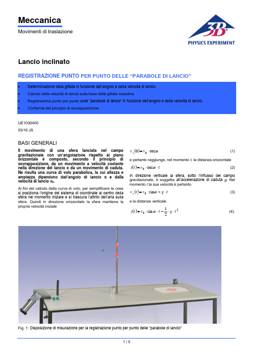
MeccanicaMovimenti di traslazioneLancio inclinatoREGISTRAZIONE PUNTO PER PUNTO DELLE “PARABOLE DI LANCIO”UE1030400 03/16 JSBASI GENERALIIl movimento di una sfera lanciata nel campo gravitazionale con un’angolazione rispetto al piano orizzontale è composto, secondo il principio di sovrapposizione, da un movimento a velocità costante nella direzione del lancio e da un movimento di caduta. Ne risulta una curva di volo parabolica, la cui altezza e ampiezza dipendono dall’angolo di lancio α e dalla velocità di lancio v 0.Ai fini del calcolo della curva di volo, per semplificare le cose si posiziona l’origine del sistema di coordinate al centro della sfera nel momento iniziale e si trascura l’attrito dell’aria sulla sfera. Quindi in direzione orizzontale la sfera mantiene la propria velocità iniziale()αcos 00⋅=v v x (1)e pertanto raggiunge, nel momento t , la distanza orizzontale()t v t x ⋅⋅=αcos 0(2)In direzione verticale la sfera, sotto l’influsso del campo gravitazionale, è soggetta all’accelerazione di caduta g . Nel momento t la sua velocità è pertanto()t g v tv y ⋅-⋅=αsin 0(3)e la distanza verticale()2021sin t g t v t y ⋅⋅-⋅⋅=α (4).Fig. 1: Disposizione di misurazione per la registrazione punto per punto delle “parabole di lancio”ELENCO DEGLI STRUMENTI1 Apparecchio di lancio1002654 (U10360) 1 Supporto per apparecchio di lancio1002655 (U10361) 1 Scala per altezza, 1 m 1000743 (U8401560) 1 Set indicatori per scale 1006494 (U8401570) 1 Piede a barilotto, 1 kg 1002834 (U13265) 1 Metro a nastro tascabile, 2 m1002603 (U10073)La curva di volo della sfera ha forma parabolica in quanto soddisfa l’equazione()()220cos 21tan xv g x x y ⋅⋅⋅-⋅=αα (5)Nel momentogv t αsin 01⋅=(6).la sfera raggiunge il punto più elevato della parabola e nel momentogv t αsin 202⋅⋅= (7).ritorna nuovamente all’altezza di partenza 0. L’altezza della parabola è quindi()α2201sin 2⋅⋅==gv t y h(8).e l’ampiezza()ααcos sin 2202⋅⋅⋅==gv t x s(9).Nell’esperimento si misurano punto per punto le curve di volo di una sfera di legno in funzione dell’angolo e della velocità di lancio con l’impiego di una scala per altezza con due indicatori (ved. fig. 3). La componente orizzontale x della curva di volo si ricava dalla distanza X orizzontale rispetto al bordo destro del supporto determinata con un metro a nastro:mm 110+=X x(10).La componente verticale y si calcola a partire dalle posizioni Y 1 e Y 2 dei due indicatori con l'assunzione che la sfera voli esattamente in mezzo. A questo proposito si deve considerare che il punto zero della misurazione dell'altezza corrisponde all'altezza del bordo superiore del tavolo, mentre la sfera parte 37,5 mm al di sopra dello stesso:mm 5,37212-+=Y Y y (11).Lo scostamento massimo del valore calcolato dal valore reale è pari amm 5,12212--=∆Y Y y (12).MONTAGGIO∙Bloccare il supporto per l'apparecchio di lancio sulla parte frontale di un tavolo lungo almeno 2 m e montare l'apparecchio di lancio secondo le istruzioni per l'uso ∙ Srotolare il metro a nastro - a partire dal bordo destro del supporto per l'apparecchio di lancio - e fissarlo sul tavolo. ∙Disporre sul tavolo il bersaglio di figura 2 su una base di 25 mm di spessore a una certa distanza dall'apparecchio di lancio.∙ Montare posteriormente una parete "di raccolta" per la sfera che rimbalza.Fig. 2: Bersaglio per l'atterraggio della sferaFig. 3: Rappresentazione schematicaAVVERTENZE PER LA SICUREZZAAnche se l'energia di lancio della sfera è molto bassa, la sfera non deve in nessun caso colpire gli occhi.∙Non guardare mai nella canna dell'apparecchio di lancio!∙Si deve controllare la posizione della sfera soltanto attraverso i fori laterali dell'apparecchio di lancio.∙Prima del lancio accertarsi che non si trovino persone nella traiettoria.ESECUZIONEDeterminazione della gittata in funzione dell'angolo di lancio∙Impostare l'angolo di lancio α = 30°.∙Disporre il bersaglio a circa 1 m di distanza.∙Caricare l'apparecchio di lancio secondo le istruzioni per l'uso fino al tensionamento minimo.∙Lanciare la sfera e seguire la traiettoria della sfera.∙Spostare il bersaglio verso il punto di impatto della sfera.∙Ripetere il lancio della sfera e correggere la posizione del bersaglio finché la sfera non atterra nel centro del bersaglio.∙Determinare la distanza X del centro del bersaglio e inserirla nella tab. 1.∙Effettuare in successione la misurazione anche per gli angoli di lancio α = 45°, 60° e 75°.∙Nella Tab. dalle distanze X secondo (10) calcolare le gittate s.Determinazione della gittata massima in funzione della velocità di lancio:∙Impostare l'angolo di lancio α = 45°.∙Caricare l'apparecchio di lancio secondo le istruzioni per l'uso fino al tensionamento medio.∙Lanciare la sfera e seguire la traiettoria della sfera.∙Spostare il bersaglio verso il punto di impatto della sfera.∙Ripetere il lancio della sfera e correggere la posizione del bersaglio finché la sfera non atterra nel centro del bersaglio.∙Determinare la distanza X del centro del bersaglio e inserirla nella tab. 2.∙Effettuare la misurazione anche per il massimo tensionamento della molla.∙Nella tab. 2 dalle distanze X secondo (10) calcolare le gittate massime s max.Registrazione punto per punto delle “parabole di lancio” in funzione dell’angolo di lancio.∙Impostare l'angolo di lancio α= 30° e posizionare il bersaglio in modo che la sfera atterri nel centro con tensionamento minimo della molla.∙Montare la scala per altezza nel piede a barilotto e disporla a X = 100 mm∙Disporre la coppia di indicatori a Y1 = 110 mm e Y2 = 140 mm.∙Lanciare la sfere con il minimo tensionamento della mollae verificare se atterra senza impedimenti nel centro delbersaglio.∙Correggere eventualmente la posizione dell'indicatore finché la sfera non atterra nel centro del bersaglio.∙Inserire i valori X, Y1 e Y2 nella tab. 3 e in base ad essi calcolare x, y e ∆y.∙Aumentare le distanze X in stadi da 50 mm e correggere rispettivamente la posizione dell'indicatore finché la sfera con tensionamento minimo della molla atterra nel centro del bersaglio.∙Effettuare le misurazioni anche per gli angoli di lancio α = 45°, 60° e 75° e riportare i risultati nelle tab. 4, 5 e 6.∙Se è disponibile sufficiente spazio per gli esperimenti eseguire misurazioni anche per altri tensionamenti della molla.ESEMPIO DI MISURAZIONEDeterminazione della gittata in funzione dell'angolo di lancioTab. 1: Gittata in funzione dell'angolo di lancio alla minima velocità di lancioTab. 2: Gittata massima in funzione della velocità di lancioRegistrazione punt o per punto delle “parabole di lancio” in funzione dell’angolo di lancio.Tab. 3: coordinate della curva di volo rispetto all'angolo di lancio α = 30°:Tab. 4: coordinate della curva di volo rispetto all'angolo di lancio α = 45°:Tab. 5: coordinate della curva di volo rispetto all'angolo di lancio α = 60°:Tab. 6: coordinate della curva di volo rispetto all'angolo di lancio α = 75°:3B Scientific GmbH, Rudorffweg 8, 21031 Amburgo, Germania, ANALISIDeterminazione della gittata in funzione dell'angolo di lancioLa figura 4 rappresenta graficamente la dipendenza della gittata s dall'angolo di lancio α sulla base dei valori di misura della tab.1. La curva disegnata attraverso i punti di misura è stata calcolata per v 0 =3,42 m/s secondo (9).α°s / mFig. 4: Gittata in funzione dell'angolo di lancioIn corrispondenza dell’angolo di lancio α = 45° viene raggiunta l’ampiezza s max di tutte le curve di volo.Determinazione della gittata massima s max in funzione della velocità di lancio v 0:Dalla gittata massima s max ottenuta a 45° può essere calcolata la velocità di lancio v 0. Grazie all’equazione 9, valemax 0s g v ⋅=I risultati sono riportati nella tab. 2.Registr azione punto per punto delle “parabole di lancio” in funzione dell’angolo di lancio.La fig. 5 mostra le curve elencate nelle tab. da 3 a 6 in rappresentazione grafica. Un'analisi precisa mostra che le curve di volo si scostano leggermente dalla forma parabolica, perché si deve considerare l'attrito dell'aria della sfera.x / c m y / c m5Fig. 5: Parabole di lancio misurate e calcolate tenendoconto dell’attrito dell’aria a velocità di lancio minima e a diversi angoli di lancio.。
简体中文Axapta生产说明书_说明
Microsoft Dynamics AX 4.0 课程 8733A:生产系列 i 教师授课须知 时间安排 教师授课须知简介 第 1 章:生产系列 I 简介 第 2 章:物料清单 第 3 章:日历、工作中心和报表 第 4 章:工序和工艺路线 第 5 章:参数、生产订单和生命周期 第 6 章:生产计划编制和外协 第 7 章:生产控制和结束 第 8 章:查询和报表 第 9 章:实践案例研究
MICROSOFT DYNAMICS AX 4.0 课程 8733A:生产系列 I
教师授课须知
最新修订时间:2007 年 12 月
本文档中所包含的信息仅代表 Microsoft Corporation 在发布之日时对所讨论问题的当前观点。由于 Microsoft 必须根据不断变化的市场情况进行调整,因此不应将此信息解释为 Microsoft 方面的承诺, Microsoft 不保证所提供的任何信息在发布日期之后的准确性。
课程用时 演示:20 分钟 演示:30 分钟 演示:110 分钟 演示:130 分钟 演示:140 分钟 演示:110 分钟 演示:60 分钟 演示:60 分钟 演示:30 分钟 演示:60 分钟
页码 1 6 8 12 15 18 21 23 25 27
第 ii 页
**仅供教师备课使用**
教师授课须知
• 评估 − 管理课程所需的任何评估。其中包括标准的 Microsoft Dynamics 课后评估。最好在课程最后一天的中间将参与 者指引到评估,以便参与者有时间完整地填写评估。
• 问题记录处 − 记下任何未回答的问题,并确定如何将答案分发给学 生。通常,获得参与者电子邮件地址并对包含后续答案的电子邮件 进行群发是一个简单的办法。
pentacam中文手册
PENETACAM 操作手册(中文)
有 LED 的开关,“ON” Pentacam HR 的数据传输。(5-poles)
2.7 起步
2.7.1 设置和安装设备
在第一次使用前,Pentacam检查 工作站必需由我们的服务部门或授权经销商 来进行设置和连接。
请把CD-ROMs妥善保存,它们包括 Pentacam的软件和标准数据。
PENETACAM 操作手册(中文)
2.2 主机
OCULUS的 Pentacam是一旋转的
检查过程中的Scheimpflug图像以及所有
Scheimpflug相机。旋转测量过程拍摄了3维的 的图像均传输至计算机。当检查结束后,计算
Scheimpflug 图像,并且通过旋转对中心点阵 机计算出3维眼前节模型,再从中得到其他信
2.4 废弃
欧洲议会2003年1月27日的
2002/96/EC规定要求所有的电子电气产品不 得通过家庭垃圾抛弃而应予以回收。
产品的包装为可回收材料。本设备的金属 部件必需送至金属加工回收。塑料和电子部件以 及线路板必需以电子垃圾处理。所有的废弃物的 处理必需符合相应国家的规定。具体情况请咨询 您所在区域的行政相关部门或者废品处理机构。
如果您放置Pentacam的房间很冷,或者 在寒冷环境中运送Pentacam,那么在环境温 度由冷转暖时,Pentacam的光学器件会有起 雾现象。请在使用Pentacam前给设备足够的 时间来适应新的环境。
根据IEC 601 – 1规定的Pentacam运输和 储藏条件:
室温:-40°C ~+70°C 湿度(包含):10% ~ 100% 气压:500 hPa ~ 1060 hPa
OCULUS Optikgeräte 管理及服务团队
阿玛达激光操作手册

2050×750×1176mm
寸 {80.71×29.53×41.57in.} {80.71×29.53×41.57in.} {80.71×29.53×41.57in.} {80.71×29.53×46.30in.}
7
第一章 控制
8
9
10
[17] STAR 按钮 在 MEMORY 或 MDI 的模式中按下后开始操作,同时在操作中按键灯点亮。 [18] STOP 按钮 停止正在进行的操作,在停止运行期间按键灯随之点亮,当再次按下此按键时终止中断模式。
c) 在操作设备时必须站在危险区以外。
d) 接通电源时不要打开激光振荡器或电源控制盒――里面有高压。
e) 不要把钥匙留在钥匙开关里,当不用时钥匙要由专门的人员保管。
f) 当你佩戴起搏器或类似的电子设备时不要靠近设备,因为设备运行时产生的 电磁波可
能干扰起搏器等设备甚至会使其失灵。
g) 不要把会反射激光光束的材料或物体放在激光头下,不要加工铜质的材料,这么做不仅会
X
80m/min
80m/min
{262.4ft/min}
{262.4ft/min}
Y
80m/min
80m/min
{262.4ft/min}
{262.4ft/min}
Z
60m/min
60m/min
{196.8ft/min}
{196.8ft/min}
工件最大重量 (只有设备)
580kg {1278.9lb}
11
但是,如果设备停止是由于安全报警引起的,此按键灯会一直亮着。 [19] EMERGENCY STOP 按钮 可以在任何模式下停止对设备的操作,被终止的操作不会恢复,只能从新开始。当按下此按键 , 按键即被锁定,只有插入钥匙并顺时针旋转才能解锁。解锁后保管好钥匙。 [20] SHUTTLE 开关 当旋转到 ON 时选择用于切割的 CO2 激光,当旋转到 OFF 时选择用于定位的 He-Ne 激光。 [21] MODE 按钮 这些按键用来选择 CNC 模式。只有当 MODE 开关旋到 ON 时这些按键才可以使用,当模式被 选定时按键灯点亮,当手动按键被按下,可以进行手轮控制盒的操作,同时所有的模式灯熄灭 , 当任何模式按键被按下或再次按下手动按键时可以恢复 CNC 控制面板操作。
ALPHA-ALPHA BOM 8 控制面板用户手册说明书

Via Lago di Vico, 44D 811430_06Thank you for buying this product, our company is sure that you will be more than satis ed with the product’s performance. The product is supplied with a “Warnings ” lea et and an “Instruction booklet ”. These should both be read carefully as they provide important information about safety, installation, operation and maintenance. This product complies with the recognised technical standards and safety regulations. We declare that it is in conformity with the follow -ing European Directives: 89/336/EEC, 73/23/EEC and subsequent amendments.1) GENERAL OUTLINEThe ALPHA-ALPHA BOM mod. control units have been designed to control one single operator.2) SCRAPPINGWarning: This operation should only be carried out by quali - ed personnel. Materials must be disposed of in conformity with the current regulations. In case of scrapping, the automation devices do not entail any particular risks or danger. In case of materials to be recycled, these should be sorted out by type (electrical components, copper, aluminium, plastic etc.).3) DISMANTLINGWarning: T his operation should only be carried out by quali edpersonnel. When t he c ontrol u nit i s d isassembled t o b e r eassembled on another site , proceed as follows:• Disconnect the power supply and the entire electrical installa -tion.• In the case where some of the components cannot be removed or are damaged, they must be replaced.4) WARNING• Make sure that an omnipolar or magnetothermal switch, having a contact opening distance equal to or greater than 3,5 mm, is tted to the automation power supply mains.• Make sure that a di erential switch with a 0.03A threshold is tted before the power supply mains.• Make sure that all safety devices installed on the gate are always in w orking o rder; o therwise, d isconnect t he p ower s upply, r elease the motors and immediately request assistance from quali ed personnel.• Do not allow persons or children to remain within the automation operation area.• Keep radio control or other control devices out of children’s reach, in order to avoid unintentional automation activation.• The user must avoid any attempt to carry out work or repair on the automation system, and always request the assistance of quali ed personnel. Correct controller operation is only ensured when the data contained in the present manual are observed. The company is not to be held responsible for any damage resulting from failure to observe the installation standards and the instructions contained in the present manual.The descriptions and illustrations contained in the present manual a re n ot b inding. T he C ompany r eserves t he r ight t o m ake any alterations deemed appropriate for the technical, manu -facturing and commercial improvement of the product, while leaving the essential product features unchanged, at any timeand without undertaking to update the present publication.Thank you for buying this product, our company is sure that you will be more than satisfied with its performance.This product is supplied with an “Instruction Manual” which should be read carefully as it provides important information about safety, installation, operation and maintenance.This product complies with recognised technical standards and safety regulations. We declare that it is in conformity with the following European Directives: 89/336/EEC, 73/23/EEC and subsequent amendments.1) GENERAL SAFETYWARNING! An incorrect installation or improper use of the product can cause damage to persons, animals or things.• The “Warnings ” leaflet and “Instruction booklet ” supplied with this product should be read carefully as they provide important information about safety, installation, use and maintenance.• Scrap packing materials (plastic, cardboard, polystyrene etc) according to the provisions set out by current standards. Keep nylon or polystyrene bags out of children’s reach.• Keep the instructions together with the technical brochure for future reference.• This product was exclusively designed and manufactured for the use specified in the present documentation. Any other use not specified in this documentation could damage the product and be dangerous.• The Company declines all responsibility for any consequences resulting from improper use of the product, or use which is different from that expected and specified in the present documentation.• Do not install the product in explosive atmosphere.• The construction components of this product must comply with the following European Directives: 89/336/CEE, 73/23/EEC, 98/37/EEC and subsequent amendments. As for all non-EEC countries, the above-mentioned standards as well as the current national standards should be respected in order to achieve a good safety level.• The Company declines all responsibility for any consequences resulting from failure to observe Good T echnical Practice when constructing closing structures (door, gates etc.), as well as from any deformation which might occur during use.• The installation must comply with the provisions set out by the following European Directives: 89/336/CEE, 73/23/EEC, 98/37/EEC and subsequent amendments.• Disconnect the electrical power supply before carrying out any work on the installation. Also disconnect any buffer batteries, if fitted.• Fit an omnipolar or magnetothermal switch on the mains power supply, having a contact opening distance equal to or greater than 3,5 mm.• Check that a differential switch with a 0.03A threshold is fitted just before the power supply mains.• Check that earthing is carried out correctly: connect all metal parts for closure (doors, gates etc.) and all system components provided with an earth terminal.• Fit all the safety devices (photocells, electric edges etc.) which are needed to protect the area from any danger caused by squashing, conveying and shearing.• Position at least one luminous signal indication device (blinker) where it can be easily seen, and fix a Warning sign to the structure.• The Company declines all responsibility with respect to the automation safety and correct operation when other manufacturers’ components are used.• Only use original parts for any maintenance or repair operation.• Do not modify the automation components, unless explicitly authorised by the company.• Instruct the product user about the control systems provided and the manual opening operation in case of emergency.• Do not allow persons or children to remain in the automation operation area.• Keep radio control or other control devices out of children’s reach, in order to avoid unintentional automation activation.• The user must avoid any attempt to carry out work or repair onthe automation system, and always request the assistance of qualified personnel.• Anything which is not expressly provided for in the present instruc-tions, is not allowed.• Installation must be carried out using the safety devices and controls prescribed by the EN 12978 Standard.2) GENERAL OUTLINEThe ALPHA-ALPHA BOM mod. control units have been designed to control one single operator.3) TECHNICAL DATAPower supply: ................................................230V±10%, 50Hz(*)Mains insulation/very low voltage: .......................> 4M Ω, 500V Working temperature: .................................................. -10 / +55°C Max. motor power absorbed: ................................................500W Dielectric strength:…. ........mains/low voltage 3750V~for 1 minute Gate-open warning light: .........................................24V~, 3W max Supply to accessories: ......................24V~, (0.2A max absorption)Incorporated Rolling-Code radio receiver: ..Frequency 433.92MHz Coding: ..................................Rolling-Code Algorithm to be cloned No. combinations: ........................................................... 4 milliard Antenna impedance: .............................................. 50Ohm (RG58)Max no. radio transmitters to be memorised: ............................. 63Dimensions: ..................................................................see figure 1(* other voltages available on request)4) TERMINAL BOARD CONNECTIONS (Fig.2)For the electric diagram and the cross section of the cables refer to the manual of the actuator.WARNING – During the wiring and installation operations, refer to the current standards as well as principles of good technical practice. Wires powered at different voltages must be physically separated, or suitably insulated with at least 1 mm extra insulation. The wires must be clamped by an extra fastener near the terminals, for ex-ample by bands.All the connection cables must be kept at an adequate distance from the dissipator.Connect the yellow/green conductor of the power supply cable to the earth terminal.230V cables must be physically separate from the safety very low voltage circuits.Keep the mains voltage connections definitely separate from the (24V) very low voltage connections.The capacitors inside the control unit must be positioned in such a way as not to decrease the surface and air distances with respect to the safety very low voltage.WARNING! For connection to the mains, use a multipolar cable with a minimum of 3x1.5mm 2 cross section and complying with the previously mentioned regulations. For example, if the cable is out side (in the open), it has to be at least equal to H07RN-F , but if it is on the inside (or outside but placed in a plastic cable cannel) it has to be or at least egual to H05VV-F with section 3x1.5mm 2.JP11-2 Power supply 230V +/- 10% 50/60 Hz (Neutral to terminal 1).3-4-5 Connection to motor M (terminal 4 common, terminals 3-5motor and capacitor drive).1-4 Connection to blinker and electric lock 230V mod. EBP .JP27-8 Alpha: START or key selector input (N.O.) Alpha BOM: ST ART or key selector input (N.O.) with trimmer TW=max. OPEN input (N.O.) with trimmer TW=min.7-9 STOP pushbutton (N.C.). If not used, leave the bridge con-nected.7-10 Photocell input or pneumatic edge (N.C.). If not used, leavethe bridge connected.7-11 Opening limit switch (N.C.). If not used, leave the bridge con-nected.D 81147-12 Closing limit switch (N.C.). If not used, leave the bridge con-nected.13-14 Output 24V~supply to photocells or other devices.15-16Output for gate-open warning light outputor alternatively 2nd radio channel.17-18 Antenna input for radio-receiver plug-in board (17 signal-18 braid).JP319-20Alpha: PEDESTRIAN input (N.O.)Alpha BOM: PEDESTRIAN input (N.O.) with trimmer TW=max.CLOSE input (N.O.) with trimmer TW=min.WARNING: the pedestrian function can be used provided that limit switches are fitted.JP4 Radio-receiver board connector, 1-2 channels.Fig.7 shows a general wiring diagram.5) LED (Fig.3)The ALPHA-ALPHA BOM control units are provided with a series of self-diagnosis LEDs which control all the functions.DL1: I ncorporated radio receiver LEDDL2: Alpha: comes on with the ST ART commandAlpha BOM:ST ART (trimmer TW=max)-comes on with the ST ART command OPEN (trimmer TW=min)-comes on with the OPEN command DL3: S TOP - goes off when a STOP command is given.DL4: P HOT - Photocell - goes off when the photocells are not aligned or in the presence of obstacles.DL5: S WO - Goes off when the opening limit switch is operated. DL6: S WC - Goes off when the closing limit switch is operated. 6) DIP-SWITCH SELECTION (Fig.3)DIP1)TCA[ON] - Automatic closing time TCA.ON: Activates automatic closingOFF: Excludes automatic closingDIP2)FCH[ON] - Photocells.ON: Photocells are only active in the closing phase.OFF: Photocells are active both in the closing and opening phase. DIP3)BLI - Blocks impulses.ON: ST ART commands are not accepted during the opening phase. OFF: START commands are accepted during the opening phase. DIP4)3P/4P - 3 Steps/4 StepsON: Enables 3-step logic.OFF: Enables 4-step logic.DIP5)CODE FIX – Fixed code.ON: Activates incorporated receiver in fixed code mode.OFF: Activates incorporated receiver in rolling-code mode.DIP6)RADIO LEARN - Radio transmitter programmingON: This enables transmitter storage via radio:1 – First press the hidden key (P1) and then the normal key (T1,T2, T3 or T4) of a transmitter already memorised in standard mode by means of the radio menu.2 – Within 10s press the hidden key (P1) and the normal key(T1, T2, T3 or T4) of a transmitter to be memorised.The receiver exits the programming mode after 10s, other new transmitters can be entered before the end of this time.This mode does not require access to the control panel. OFF: This disables transmitter storage via radio. The transmitters are only memorised by means of manual programming.DIP7)SCA – Gate-open warning light or 2nd radio channel.OFF: Activates relay output in Gate-open warning light mode. ON: Activates relay output as 2nd radio channel.DIP8)FAST CLOSEON: Closes the gate after photocell disengagement, before waiting for the end of the TCA set.OFF: Command not entered.7) TRIMMER ADJUSTMENT (Fig.3)TCA (Dip1 ON).It is used to set the automatic closing time, after which the gate closes automatically (adjustable from 0 to 90 s.).TWAlpha:Sets the motor working time (from 0 to 90s), after which the motors stop.In the case where electrical limit switches are used,add a few extra seconds after the gate leaf stoppingtime.Alpha BOM:Working time is fixed to 10s.trimmer TW = min: inputs 7-8 and 19-20 are considered as OPEN and CLOSE inputs respectively.trimmer TW = max: inputs 7-8 and 19-20 are considered as START and PEDESTRIAN inputs respectively.8) INTEGRATED RECEIVER TECHNICAL SPECIFICATION Receiver output channels:- output channel 1, if activated, controls a ST ART command- output channel 2, if activated, controls the excitation of the 2nd radio channel relay for 1s.Transmitter versions which can be used:all Rolling Code transmitters compatible with . ANTENNA INSTALLATIONUse an antenna tuned to 433MHz.For Antenna-Receiver connection, use RG8 coaxial cable.The presence of metallic masses next to the antenna can interfere with radio reception. In case of insufficient transmitter range, move the antenna to a more suitable position.9) PROGRAMMINGTransmitter storage can be carried out in manual mode, or by means of the Universal palmtop programmer which allows you to create installations in the “collective receivers” mode, as well as manage the complete installation database using the EEdbase software. 10) MANUAL PROGRAMMINGIn the case of standard installations where no advanced functions are required, it is possible to proceed to manual storage of the transmitters1) I f you wish the transmitter T key to be memorised as Start, press thSW1 button on the control unit, otherwise if you wish the transmitter key to be memorise as second radio channel, press the SW2 button on the control unit.2) W hen the DL1 LED blinks, press the transmitter P1 hidden key, and the DL1 LED will stay on permanently.3) P ress the key to be memorised on the transmitter, LED DL1 will start blinking again.4) T o memorise another transmitter, repeat steps 2) and 3).5) T o exit the storage mode, wait until the LED is switched off com-pletely.IMPORTANT NOTE: ATTACH THE ADHESIVE KEY LABEL TO THE FIRST MEMORISED TRANSMITTER (MASTER).In the case of manual programming, the first transmitter assigns the key code to the receiver; this code is necessary in order to carry out subsequent cloning of the radio transmitters.10.1) CONTROL UNIT MEMORY CANCELLATIONIn order to cancel the control unit memory completely, simultaneously press for 10 seconds the SW1 and SW2 buttons on the control unit (DL1 LED blinking). Correct memory cancellation will be indicated by the DL1 LED staying on permanently. T o exit the storage mode, wait until the LED is switched off completely.D811411) RECEIVER CONFIGURATIONThe on-board receiver combines characteristics of utmost safety in copying variable code (rolling code) coding with the convenience of carrying out transmitter “cloning” operations thanks to an exclusive system.Cloning a transmitter means creating a transmitter which can be automatically included within the list of the transmitters memorised in the receiver, either as an addition or as a replacement of a par-ticular transmitter.Cloning by replacement is used to create a new transmitter which takes the place of the one previously memorised in the receiver; in this way a specific transmitter can be removed from the memory and will no longer be usable.Therefore it will be possible to remotely program a large number of additional transmitters or, for example, replacement transmitters for those which have been lost, without making changes directly to the receiver.When coding safety is not a decisive factor, the on-board receiver allows you to carry out fixed-code additional cloning which, although abandoning the variable code, provides a high number of coding combinations, therefore keeping it possible to “copy” any transmitter which has already been programmed .12) RADIO-TRANSMITTER CLONING (Fig.7)Rolling-code cloning / Fixed-code cloningMake reference to the universal palmtop programmer instructions and the CLONIX Programming Guide.12.1) ADVANCED PROGRAMMING: COLLECTIVE RECEIVERS Make reference to the universal palmtop programmer Instructions and the CLONIX Programming Guide.13) ACCESSORIES SPL (fig.4).Pre-heating optional board. Recommended for temperatures below -10°C. (In the case of hydraulic motors).ME (fig.5).Optional board used to connect a 12V ~ electric lock.Note: the ME optional board is not operated by the ST ART control of the integrated radio board. For the correct functioning of the ME optional board use one of the following configurations:1. use the second radio channel as ST ART control and perform the necessary connections to the terminal board.2. use the plug-in radio receiver. EBP (fig.2).The EBP electric lock with continuous service can be connected directly to terminals 1 and 4.14) SCRAPPINGWarning: This operation should only be carried out by qualified personnel. Materials must be disposed of in conformity with the current regulations. In case of scrapping, the automation devices do not entail any particular risks or danger. In case of materials to be recycled, these should be sorted out by type (electrical components, copper, aluminium, plastic etc.).15) DISMANTLINGWarning: T his operation should only be carried out by qualified personnel. When the control unit is disassembled to be reassembled on another site , proceed as follows:• Disconnect the power supply and the entire electrical installation. • In the case where some of the components cannot be removed or are damaged, they must be replaced.The descriptions and illustrations contained in the present manual are not binding. T he Company reserves the right to make any alterations deemed appropriate for the technical, manu-facturing and commercial improvement of the product, while leaving the essential product features unchanged, at any time and without undertaking to update the present publication.D 8114D 811430_06D 811430_06。
A510注塑机适配卡APA-A312中文使用说明书V1.0

F0.1.17 运行方式(H)
0000 0000 根据现场需求来设置
F0.1.18 频率 1 作用系数 1.00 1.00
F0.1.20 最大输出频率
60Hz 100Hz
F0.1.21 上限频率
50Hz 50Hz
F0.1.22 下限频率
0Hz 0Hz
F0.2.28 频率设定 1 最大值 50Hz 80Hz
与工作现场无缝连接; 4. 灵活的功能配置,最大程度满足各类客户的使用需求; 5. 可实时监控输入模拟量,及指令频率,调试简单、安装方
便。
控制端子
接线端子排列如下:
图 1 注塑机(一体机)适配卡控制端子示意图
1道 1
模 拟 输 入
专用输入 通道 2
符号 VC1 CC1 CM1 VC2 CC2 CM2
F0.3.33 控制命令 1
0
1 外部端子控制
F0.3.35 外部端子作用模式 0
0 两线模式 1
F1.0.00 加减速特性参数 0000 0000 直线加速
将 F0.0.09 配置为无感矢量(SVC)模式时,请检查相关 参数设置:F2.0.00~F2.0.10,请使用电机参数测定功能对电 机进行参数辨识,以发挥 A510/CA500 系列产品的最佳性能。 具体的方法为将 F2.2.53 设为 1,启动一次电机,约 30 秒后 停止辨识即可。
T DI1
电压通道 1
电流通道 1 公共端 1
CM2 VC1 CC1 CM1
机
扩
FWD正转
展
REV反转
卡
RST复位
DI2 DI3 DI4 DI5
( 选配 )
DI6
CM
E
DO1 DO2 CM E
Bambora APAC Payment Extension 2020 用户指南说明书

***************** BAMBORA APAC PAYMENTMODULE FOR MAGENTO 2USER GUIDEVersion 1.0.0Table of Contents1.INTRODUCTION (2)2.HOW TO USE AND CONFIGURE (3)2.1 License Key Settings (3)2.2Bambora Payment Method Management …...................................................................3.FRONT END………………………………………………………………………………4 71. INTRODUCTION•Magento Bambora APAC payment gateway extension specializes for capturing payment from credit and debit card to your Bambora account for Asia Pacific regions.•Rootways Bambora APAC Extension is very easy to install and configure. Just enable payment method, add your Bambora information and you can use Bambora APACPayment Method for your website.•No technical knowledge required!Features Listing:•Bambora's Checkout.js makes it more secure.•Submit the credit card details on a safe and secure Bambora server iFrame rather than your Magento server.•Choose payment action as Authorize Only or Authorize and Capture.•Refund payment from Magento 2 store admin.•Supports partial capture and refund.•Accept major credit cards.•Multi store supported.•Supports multiple currencies.•Set minimum and maximum order total for allow payment method.•Easy to install and configure.•User Friendly Interface.•Reliable and prompt support by Rootways.2. HOW TO USE AND CONFIGUREThis section will guide you to configure Rootways Bambora APAC Payment Gateway Extension. It's very easy and fast!2.1License Key Settings:Log in to Admin Panel and then click STORES →Configuration →ROOTWAYS EXTENSIONS →Bambora APAC Payment→Settings.Below is the screen shot of Bambora APAC Payment Gateway license key settings. Please enter license key for this extension that was emailed by us to you after your purchase.2.2 Bambora APAC Payment Method Management:Go to STORES → Configuration → SALES → Payment Methods → Bambora APAC Payment Method - by Rootways Inc.You can see below screen. Fill up all required detail and save it.•Enable: You can enable/disable this payment method using this option.•Title: Title of the payment method to be visible at front side.•Payment Mode: Choose whether its test or live mode of payment method.•Merchant ID - Test/Live Account: Add merchant ID of Bambora APAC test/live account.•Account Number - Test/Live Account: Add account number of Bambora APAC test/live account.•User Name - Test/Live Account: Add username of Bambora APAC test/live account.•Password - Test/Live Account: Add password of Bambora APAC test/live account.•Enable Checkout.js: Choose “Yes” to enable Checkout.js for your Magento store.General Settings:•Credit Card Types: Choose type of credit cards that you want to display at front-end.•Payment Action: Choose whether it's Authorized Only or Authorized and Capture.•Payment from Applicable Countries: Choose whether you want to allow payment method for all or specific countries only.•Payment from Specific Countries: Select countries in which you want to allow this payment method.•Debug: Choose “Yes” if you want to keep the debug mode on.•Minimum Order Total: Add minimum order amount applicable for this payment method.•Maximum Order Total: Add maximum order amount applicable for this payment method.•Sort Order: Sort order of this payment method at checkout page.FRONT END:After setting up Bambora APAC Payment Method you can see it on the checkout page, as in the screenshot below. Now you can capture ample amount of orders using Bambora APAC.Our Website: https:///Email: *****************Phone: 1-855-766-8929------------------------- THANK YOU -------------------------。
阿伯塔马伯特大西洋自动洗车系统用户手册说明书

Alberta Motor Association re-paves document system forWhen AMA replaced slow-moving systems with OpenText up-to-the-minute, centralized document access, digital construction re-paved back-office operations leading to an increased flow of business traffic. Desk-to-desk paper processesFor more than 50 years, the Alberta Motor Association (AMA)—affiliated with the Canadian Automobile Association (CAA) and its “Triple A” American counterpart—has provided auto, home, health and other insurance plans. Nearing one million people, close to one in every three households in Alberta, Canada, maintains membership with the AMA. To sustain and grow this coverage, AMA advocates for member interests at the industry and government levels and protects the things members care about most with insurance services.Prior to implementing an electronic document management system, management of underwriting and claims was a laborious, paper-based process. Personnel at each AMA location were required to manually organize and box paper documents for delivery to large file rooms where dozens of staff members re-handled the vast array of documents, filing them in large cabinets.Even as document imaging was introduced, paper files were still routed desk-to-desk before being shipped to a central department for scanning. The process often caused paper loss or delays—as much as two weeks to two months—for policy origination, claims management and other tasks. Furthermore, a lack of integration between their in-house developed sales claims and underwriting system and legacy document management system, as well as complicated searching led to slow or duplicate efforts; staff members complained of time wasted tracking down documents, which affected the response time to customers.Integrating content in the sales and claims management processWhen its insurance sales and claims management legacy system reached end-of-life, AMA seized the opportunity to rebuild their processes and the technology used to support them. The provider built a new insurance production system and claims case management system and integrated it with OpenText™ Content Suite Platform, a comprehensive enterprise content management (ECM) system designed to manage the flow of information from capture through archiving and disposition. Following a thorough investigative process, AMA’s selection committee chose OpenText for its ease-of-use and straightforward integration. Now, AMA insurance professionals—from sales advisors and administrators to underwriters and claims advisors—access critical information at any time directly through a button within the insurance production and claims case management system labeled “Livelink,” connecting to more than 16 million digital documents. When new files arrive from external sources in hard copy form, they are scanned, reviewed for quality and uploaded to Content Suite. AMA also added Content Suite workflow functionality so these transactions can be processed in the insurance production and claims case management system, then routed to the correct claims case management folder in Content Suite.AMA professionals now easily share files or collaborate on operational tasks without the delays of moving the physical files from desk-to-desk. “A claims advisor can review a file while somebody else in a different office can simultaneously access the same document, providing their permissions are set appropriately,” noted David Panteluk, manager of system development with AMA. He described revised document manage-ment procedures at all stages of the insurance process:Sales—Frontline agents use the in-house system for point-of-sale transactions. Policy documents are created, then stored in and retrieved from Content Suite. “Customers come in to buy a policy from us and walk away a few minutes later with the documents they need,”Panteluk said.Underwriting—Back office personnel use the system for underwriting insurance risk. They link directly from policy transactions to view supporting documents within Content Suite.Claims management—Claim advisors use the system to confirm insur-ance coverage; to settle claims, appraisers upload files, such as photos and reports and advisors access all files through Content Suite.As an add-on to Content Suite, AMA uses content-centric applications OpenText™ Brava!™ for Content Suite to ease collaboration and OpenText™WebReports, to configure and automate real-time dashboards and in-tegrated reporting. The provider plans to leverage other ECM capabilities from OpenText Content Suite, including records management and archiving. Documents within minutes supports more businessBy re-paving document back roads, AMA is increasing and expediting traffic flow on the sales and processing fronts. “Historically, retrieving a document would take two weeks on average and occasionally up to three months. Compare that with today, where documents are available in real time and put to use within minutes,” Panteluk said. Efficiency translates into fewer personnel handling more demands in shorter timeframes—all enhancing service to members, AMA’s constant focus. Results are apparent across the insurance operation:Sales—An agent sells a policy, signed and supporting documents are scanned at the agency and entered into a workflow for verification. “Within an hour or two, there is digital representation of all corre-sponding documentation in Content Suite, which is available across the organization,” Panteluk noted. “That’s a big leap from where we used to be when it could take up to 90 days before those documents were processed and available.”Underwriting—“We don’t have file clerks running to retrieve files and storing documents, but we’ve grown with the number of underwriters that we have,” Panteluk said. “So, we’re able to do more business and to provide better support to our front-end advisors who are then helping our customers faster.”Claims management—Due to tight integration between the claims case management system and Content Suite, the days of file requests and multi-day waiting periods are over. “That’s really helped our claims process,” Panteluk noted. “Maintaining hard copies of our claims documents was cumbersome and slow. Now we’re moving forward with a much faster, slicker and more efficient solution.” In fact, at one time impossible with the previous document management system, AMA professionals collaborate on documents within minutes or, at least, the same day.“Overall, we are improving our processes significantly,” Panteluk said. “Our agents confidently speak with members around our document retention and retrieval processes.” Such confident, immediate service is available across the enterprise—all offices, regardless of where policies are purchased, leverage the same document access to answer customer questions.AMA continues to observe cost-savings afforded by digital manage-ment. For instance, mailing costs are drastically reduced and thecompany re-purposed a 300-square-foot file room to office space for staff members, many of whom accepted paperless systems readily. “We’re hearing positive responses that show they trust OpenText Content Suite,” Panteluk said. Wasted time and difficulty to locate files is gone and word is getting out: other AMA operating companies including Driver Education, Roadside Assistance and Membership want to upload documents to Content Suite as well.About OpenTextOpenText, The Information Company, enables organizations to gain insight through market leading information management solutions, on-premises or in the cloud. For more information about OpenText (NASDAQ: OTEX, TSX: OTEX) visit . Customer stories /contact Twitter | LinkedInCopyright ©2018 Open Text. OpenText is a trademark or registered trademark of Open Text. The list of trademarks is not exhaustive of other trademarks. Registered trademarks, product names, company names, brands and service names mentioned herein are property of Open Text. All rights reserved. For more information, visit: /2/global/site-copyright.html 09752A.1ENThe most important result for AMA is member benefits. “With the integra-tion between our production system and OpenText Content Suite, our employees don’t have to work as hard on processes, they can focus on serving the customer,” Panteluk said. “We’re creating value by being able to serve our members better.”。
Parker PAC终端用户手册说明书

1. 2. 3. 4. 5. 6. 7.
LED Power Indicator
Ethernet Connection
1. 2.Байду номын сангаас
Parker PAC Terminal User Manual
Ethernet Status LED’s
How to obtain Technical Assistance from Parker Hannifin
ADDITIONAL INFORMATION Parker PAC Terminal User Manual
Environmental Specifications
Environmental Specifications Table
Parker PAC Terminal User Manual
Connection Diagram
SYSTEM START-UP AND CONFIGURATION
Installing an Optional AC Power Supply
Mounting the Optional PS-60W AC Power Supply
Installation Safety Requirements
Parker PAC Terminal User Manual
Installation Guidelines
Regulatory Installation Guidelines
Thermal Guidelines
º º
º º
Physical Specifications
Physical Specifications Table
ALPHACAM中文使用手册之欧阳结创编

第一章简介关于使用本手册本手册系提供程序的使用及操作的详细说明。
通常您可在程工主画面的辅助说明中寻找相关的使用说明。
而本手册则是更详细,依照章节的画面说明。
此手册应在使用软件之后,有所疑问,再来查询之用。
本手的习惯用法应按何键,系统以完整符号表示,如:[Enter] , [Esc] , [Tab ], [Ctrl ] , [Shift ], [Spacebar ] , [F4 ] , [A ] , [B ] , [S]等。
而二键同时按时,则以:[Ctrl ] + [S]表示。
而键须依序而按,则以:[Atl ] , [F ], [O]表示。
在程序操作时,而鼠标最常用到。
在手册中,按鼠标系以“按”及符号Θ表示。
按鼠标右键则为R-Θ。
按鼠标2次,则以“按二次”说明,而以符号2Θ表示按鼠标左键二次。
而按左键一次选取,则以Θ符号表示。
指令及选项的使用时,则以粗黑大字表示。
主菜单及次选项是以阶层表示。
例如:几何图形|弧 |二点+半径。
黑三角表示主菜单下,它会再开一个次选项视图。
若是同一主菜单下,有多个指令要使用,全阶层表示则代繁锁,则次选项则以|拷贝|来表示。
指令选用可以用滑或键。
若用键躩,先按Atl,再依序按下标线的字母。
例如:Atl,F,O,表示档案|开始旧文件…指令。
另一个指令选取法,是所谓的“热键”。
其法表示在选项屏幕中,以“Ctrl+键”表示,例如:档案|储存档案Ctrl+S。
使用时,即先按Ctrl键。
手册以Ctrl+Spacebar表示。
大部份指令有一更快速,直接的选用法:“图像”按钮。
若此指令有图像钮可供选用,则会在指令到列的最后以其图像显示出来,例如:几何图形|APS快速几何图形|线到弧熔接若该指令还有“热键”,则会在它的指令列及图像之后,再把热键列出,例如:档案|开启档案 Ctrl+O.开/关的指令,表示“开”或“关”则是在指令的前面打上一个勾勾表示。
例如:显示|显示选项| ˇ显示断点。
若指令之后,会带出一对话框,供再选取指令,则是在指令之后,以小点点表示,如下:几何图形|编辑/列出几何图形…对话框指令的选用同前表示尖法,只是以一大粗线符号表示而已,例如:加工|刀具方向边|更改出/进L/R。
- 1、下载文档前请自行甄别文档内容的完整性,平台不提供额外的编辑、内容补充、找答案等附加服务。
- 2、"仅部分预览"的文档,不可在线预览部分如存在完整性等问题,可反馈申请退款(可完整预览的文档不适用该条件!)。
- 3、如文档侵犯您的权益,请联系客服反馈,我们会尽快为您处理(人工客服工作时间:9:00-18:30)。
Apama介绍通知有关详细信息,请参见以下主题:版权第三方致谢声明版权保留所有权利。
© 2011 Progress Software Corporation和/或其子公司或附属公司或其子公司或附属公司。
保留所有权利本文档以及所有Progress® 软件产品均受版权保护,所有权利均归Progress Software公司所有。
本文档信息有可能发生变化,恕不另行通知,Progress Software公司不对文档中可能出现的任何错误承担责任。
本文档所提及的产品所支持的平台有可能发生变化。
Actional ,Apama ,Artix ,Business Empowerment ,Business Making Progress ,DataDirect (以及设计),DataDirect Connect ,DataDirect Connect64,DataDirect Technologies ,DataDirect XML Converters ,DataDirect XQuery ,DataXtend ,Dynamic Routing Architecture ,EdgeXtend ,Empowerment Center ,Fathom ,Fuse Mediation Router ,Fuse Message Broker ,Fuse Services Framework ,IntelliStream ,IONA ,Making Software Work Together ,Mindreef ,ObjectStore ,OpenEdge ,Orbix ,PeerDirect ,POSSENET ,Powered by Progress ,PowerTier ,Progress ,Progress DataXtend ,Progress Dynamics ,Progress Business Empowerment ,Progress Empowerment Center ,Progress Empowerment Program ,Progress OpenEdge ,Progress Profiles ,Progress Results ,Progress Software Business Making Progress ,Progress Software Developers Network ,Progress Sonic ,ProVision ,PS Select ,Savvion ,SequeLink ,Shadow ,SOAPscope ,SOAPStation ,Sonic ,Sonic ESB ,SonicMQ ,Sonic Orchestration Server ,SpeedScript ,Stylus Studio ,Technical Empowerment ,WebSpeed ,Xcalia (与设计),以及Your Software ,Our Technology–Experience the Connection 均为Progress Software Corporation 或其附属公司或子公司在美国和/或其他国家的注册商标。
AccelEvent ,Apama Dashboard Studio ,Apama Event Manager ,Apama Event Modeler ,Apama Event Store ,Apama Risk Firewall ,AppsAlive ,AppServer ,ASPen ,ASP-in-a-Box ,BusinessEdge ,Cache-Forward ,CloudEdge ,DataDirect Spy ,DataDirect SupportLink ,Fuse ,FuseSource ,Future Proof ,GVAC ,High Performance Integration ,ObjectStore Inspector ,ObjectStore Performance Expert ,OpenAccess ,Orbacus ,Pantero ,POSSE ,ProDataSet ,Progress Arcade ,Progress CloudEdge ,Progress Control Tower ,Progress ESP Event Manager ,Progress ESP Event Modeler ,Progress Event Engine ,Progress RFID ,Progress RPM ,PSE Pro ,SectorAlliance ,SeeThinkAct ,Shadow z/Services ,Shadow z/Direct ,Shadow z/Events ,Shadow z/Presentation ,Shadow Studio ,SmartBrowser ,SmartComponent ,SmartDataBrowser ,SmartDataObjects ,SmartDataView ,SmartDialog ,SmartFolder ,SmartFrame ,SmartObjects ,SmartPanel ,SmartQuery ,SmartViewer ,SmartWindow ,Sonic Business Integration Suite ,Sonic Process Manager ,Sonic Collaboration Server ,Sonic Continuous Availability 架构,Sonic Database Service ,Sonic Workbench ,Sonic XML Server ,The Brains Behind BAM ,WebClient ,以及Who Makes Progress 均为Progress Software 公司和/或其子公司或附属公司在美国以及其他国家的商标或服务标志。
Java 是Oracle 和/或其附属公司的注册商标。
本文档包含的所有其他标志均为其各自所有人的商标。
第三方第三方致谢声明致谢声明Progress Apama v4.3.3采用了ANTLR 2.7.6。
此技术受以下条件与条款的限制:《软件权利》(SOFTWARE RIGHTS )。
ANTLR 1989-2005 由Terence Parr Partially 在旧金山大学和 的支持下开发。
我们对ANTLR 不拥有任何法律权利――该技术完全属于公共领域。
个人或公司可以对ANTLR 发布的源代码或由ANTLR 产生的代码进行任何操作,包括将ANTLR 或其输出用于商业软件。
我们鼓励用户使用ANTLR 开发软件。
不过,我们要求用户认可我们开发ANTLR 的贡献。
此处的“认可”意为,如果您将ANTLR 或其任何源代码用于您的程序(商业产品、研发项目或其他),请您在文档、研究报告等资料中提及这一事实...如果您喜欢ANTLR ,并使用其输出开发出了优秀的工具,也请提及您使用ANTLR 开发出了这种工具。
此外,我们要求源代码中的标头保持不变。
在遵守以上指南的前提下,我们将继续改进此系统,并将在研发完成后提供其他工具。
ANTLR 主要研发者:Terence Parr ,parrt@ ,parrt@Progress Apama v4.3.3采用了Jakarta commons - bean utils v1.6,commons-collection v 2.1,commons-digester v1.5,以及Jakarta Struts v1.1。
此技术受以下条件与条款的限制:Apache 软件许可,Version 1.1 版权所有(c ) 1999-2001 Apache Software Foundation 。
保留所有权利。
在遵守以下条件的前提下,可再发布软件或以源代码及二进制形式使用软件,包括进行修改或不进行修改:1. 源代码的再发布必须遵守上述版权通知、本条件列表以及以下免责声明。
2. 以二进制形式再发布软件时必须复制上述版权通知、本条件列表以及文档下文中的免责声明和/或发布代码时提供的其他信息。
3. 再发布时提供的最终用户文档(如有)必须包含以下致谢声明:“本产品包括由Apache Software Foundation (/)开发的软件。
”也可在软件中加入此致谢声明,只要确保此类第三方致谢声明顺利呈现即可。
4. 在未得到事先书面批准的情况下,不得将名称“The Jakarta Project ”、“Struts ”以及“Apache Software Foundation ”用于支持或推广此软件的衍生产品。
如需获得书面许可,请联系apache@.5. 在未获得Apache Group 事先书面许可的情况下,本软件衍生产品不得被称为“Apache ”,其名称中也不能出现“Apache ”字样。
本软件以本软件以本软件以““按现状按现状””为基础提供,不提供任何明确或暗示的保证不提供任何明确或暗示的保证,,包括但不限于包括但不限于本软件针对特定用途的可售性及适用性本软件针对特定用途的可售性及适用性的暗示保证的暗示保证。
在任何情况下在任何情况下,,APACHE SOFTWARE FOUNDATION 或其贡献者均不对因使用本软件而以任何方式产生的任何直接软件而以任何方式产生的任何直接、、间接间接、、偶然偶然、、特殊特殊、、典型或相因而生的损失典型或相因而生的损失((包括但不限于不限于采购替换产品或服务采购替换产品或服务采购替换产品或服务;;使用价值使用价值、、数据或利润的损失数据或利润的损失;;或业务中断或业务中断))而根据任何责任理论任理论,,包括合同包括合同、、严格责任或侵权行为严格责任或侵权行为((包括疏忽或其他包括疏忽或其他))承担任何责任承担任何责任,,即使在已经提醒可能发生此类损失的情况下提醒可能发生此类损失的情况下。
=============================================================================== 本软件包括多位人士代表Apache Software Foundation 自愿做出的贡献。
有关Apache Software Foundation 的详细信息,请参见/。
Progress Apama v4.3.3采用了ANTLR 3.1.2。
此技术受以下条件与条款的限制: ANTLR 3 License[The BSD License] 版权所有(c ) 2003-2008,Terence Parr 保留所有权利。