最新NSK直线导轨安装说明书
自动化生产线直线导轨挡块的安装方法

自动化生产线直线导轨挡块的安装方法下载提示:该文档是本店铺精心编制而成的,希望大家下载后,能够帮助大家解决实际问题。
文档下载后可定制修改,请根据实际需要进行调整和使用,谢谢!本店铺为大家提供各种类型的实用资料,如教育随笔、日记赏析、句子摘抄、古诗大全、经典美文、话题作文、工作总结、词语解析、文案摘录、其他资料等等,想了解不同资料格式和写法,敬请关注!Download tips: This document is carefully compiled by this editor. I hope that after you download it, it can help you solve practical problems. The document can be customized and modified after downloading, please adjust and use it according to actual needs, thank you! In addition, this shop provides you with various types of practical materials, such as educational essays, diary appreciation, sentence excerpts, ancient poems, classic articles, topic composition, work summary, word parsing, copy excerpts, other materials and so on, want to know different data formats and writing methods, please pay attention!1. 简介在自动化生产线中,直线导轨挡块的安装是确保设备正常运行和产品质量稳定的关键步骤之一。
直线导轨拼接处安装标准

直线导轨拼接处安装标准# 直线导轨拼接处安装标准## 一、前言嘿,朋友!你知道在很多机械设备里,直线导轨那可是相当重要的部件呢。
它就像火车的铁轨一样,能让设备的某个部分沿着它精准地移动。
但是有时候呀,因为设备比较长或者其他特殊需求,我们就需要把直线导轨拼接起来。
这就好比铺很长的铁轨,中间得接好喽,不然火车跑起来可就麻烦了。
所以呢,咱们今天就来好好聊聊直线导轨拼接处的安装标准,这样大家在安装的时候就有个准儿,能让设备运行得又稳又好。
## 二、适用范围1. 机床设备- 比如说数控机床,它的工作台常常需要沿着直线导轨做精确的移动。
如果直线导轨拼接处安装不好,那加工出来的零件精度可就没法保证了。
像加工一些精密的模具或者航空零件,误差哪怕只是一点点,那整个零件可能就报废了。
2. 自动化生产线- 在自动化流水生产线上,有很多部件是通过直线导轨来实现精确传输的。
例如在汽车生产线上,车身部件在不同工序间的移动靠的就是直线导轨。
如果拼接处有问题,可能会导致部件传输不畅,影响整个生产线的效率。
3. 测量仪器- 像三坐标测量仪这种高精度的测量设备,它的测量头在导轨上移动来获取精确的测量数据。
要是直线导轨拼接处不符合标准,测量的数据就会不准确,那测量结果可就大打折扣了。
## 三、术语定义1. 直线导轨- 简单来说呢,直线导轨就是一种能够让物体沿着直线方向平滑移动的装置。
它通常由导轨和滑块组成,就像轨道和在轨道上行驶的小车一样。
导轨是固定在设备上的那个长条部分,滑块则是套在导轨上,可以带着其他部件来回滑动的部分。
2. 拼接处- 这就是当我们把两段或者多段直线导轨连接在一起的那个地方。
就好比我们把两根短的铁轨接起来的那个接头处,这个地方要是没处理好,就会影响整个导轨的性能。
## 四、正文(一)安装前的准备工作1. 导轨的检查- 化学成分方面,要确保导轨的材料符合设计要求。
一般来说,优质的直线导轨采用的是高强度合金钢,这种材料具有良好的耐磨性和抗腐蚀性。
直线导轨参数及安装
认识直线导轨-导轨的详细参数来源:Hiwin直线导轨官网作者:直线导轨时间:2010-01-29 12:06 我要投稿21世纪起人类对地球环境保护意识日益高涨,各式工业产品均朝向环保化与节能高效率的潮流发展。
线性传动产品的设计理念上,当然也必须符合时代的要求,朝向高速化、高精度化、复合化与环保节能化的趋势,如何引进环保节能化的概念引起线性滑轨的诞生。
线性滑轨广泛运用于精密机械、自动化、各种动力传输、半导体、医疗和航太等产业上,均具有极为关键的地位。
本文将引导读者了解线性滑轨的应用参数及相互关系,让读者在选用及安装线性滑轨能有一定的参考数据应用能力。
有关如何选择适用的线性滑轨及如何安装线性滑轨请参阅下二篇文章。
1-1线性滑轨名词介绍主要影响参数a、线性滑轨之负荷与寿命(L)线性滑轨选用型号时,根据机构使用条件及所受外力,可藉由工程计算求出机构中每一个滑座所受外力影响产生的负载,而型录上记载的基本静额定负载(C0)或基本容许静力矩(Mx、My、Mz)等参数,将滑座等效负载求出予以比较,可以求出静安全系数,用以判断机构对于外力的抵抗程度。
而线性滑轨评估长期磨耗使用寿命则是利用基本动额定负载(C),可求出线性滑轨因长期往复负载导致发生金属疲劳之表面破坏的总行程距离。
b、基本额定静负荷(C0)当线性滑轨系统于静止或低速运行中受到过大的负载或冲击,轨道沟槽及钢珠会发生永久变形,假设此变形量达到某个程度,此线性滑轨就无法运行顺畅。
而基本额定静负载(C0)即为静止负载作用在轨道沟槽及钢珠产生的总永久变形量达到钢珠直径的万分之一时的静止负荷。
c、基本容许静力矩(Mx,My,Mz)当线性滑轨系统受到负载或冲击而产生力矩时,使线性滑轨发生轨道沟槽及钢珠的永久变形,当永久变形量达到钢珠直径的万分之一时。
我们称这种作用力矩为滑座的基本容许静力矩。
而Mx、My、Mz为在线轨X、Y、Z三个轴向的值。
如下图所示W'、接牺係撤MOt 容計許力矩M : St 計力矩 以下为静安全系数的参考值操作条件 负载条件 最小之fs一般静止轻冲击和偏移 1.0 〜1.3重冲击和扭转 2.0 〜3.0一般运行轻冲击和扭转 1.0 〜1.5重冲击和扭转2.5 〜5.0•共4页:•上一页• 1• 2• 3* 4*下一页 d 、静安全系数 (fs )为基本额定静负荷CO 与线性滑轨系统最大等效负载之比率值。
NSK直线导轨操作使用说明书

8
除去塑料纸包装,可看见在直线导 轨的导轨侧面印有产品的型号和生产编 号,在滑块的侧面也印有生产编号。
导轨以及滑块侧面的凹槽指明了基 准面。
凹
两根导轨看起来相似,但是一个是 基准导轨,其基准面对应于轨道滑块基 准面可以控制尺寸变化,同时与工作台 上的相应基准面配合。如果其它的滑块 靠着工作台基准面安装。则工作台就会 像如图虚线所示歪斜。在两轴(笛卡尔) 工作平台情况下,不能获得精确的两轴 方形。
其线性和平行度用如下方式测量。
测量每个 A 表面的线性度:把一个 合适的测量块放在一个表面,并且把千 分表的铁笔放在平行于 A 表面的直尺 上,测量块牢固地贴紧 B 表面。沿着 A 表面按指定的步调滑动,记录量得的尺 寸,接着重复同样的步骤直到轨道末端。
基准端
A 表面
5
接下来对另一个 A 表面重复上述操 作。当进行上述测量时,要注意不能移 动直尺。
正确存放
a 如果导轨以不当的方式存放,会引 起直线导轨的弯曲变形。所以进行 保管的时候,请把导轨放在水平位 置。
1
NSK 直线导轨的安装 [第一部:机床篇]
感谢您对 NSK 直线导轨的关注。本 部旨在介绍如何操作 NSK 直线导轨以及 如何以指定的精度将其安装到机床上的 步骤。
对于 NSK 直线滚珠导轨在机床上的 应用,我们推荐用两种形式的导轨。其 一是 LA 系列,这一系列的导轨具有与直 线滚子导轨相同的高刚性,高可靠耐用 性,以及高耐冲击负载容量。其二是 LY 系列,这一系列的导轨已普遍使用于机 床行业。
直线导轨 安装说明书
NSK 直线导轨 型录说明书

NSK's standard Linear Guide series, NH and NS series, attains a significant increase in durability, satisfies the requirements of every industry with its versatile performance and conforms to international standard dimensions. Features: Long operating life High speed Wide variety CAT. No.E3332 ( KB) NSK Online Interactive Catalogs and Tools give you the capability to select the correct bearings that best meet the needs of your application and equipment design. The selection tools for ball screws, NSK Linear Guides, and Megatorque Motors are also available. 2D/3D CAD data for NSK products is available through PARTcommunity. This free service is provided by CADENAS GmbH. Every care has been taken to ensure the accuracy of data in this publication, but NSK Ltd. accepts no liability for any loss or damage incurred from errors or omissions. As we pursue continuous improvement, all content (text, images, product appearances, specifications, etc.) contained in this publication is subject to change without notice. Unauthorized copying and/or use of the contents of this publication is strictly prohibited. Please investigate and follow the latest product export laws, regulations, and permit procedures when exporting to other countries. Please use the online catalog to select bearings. No catalog Spindelmutter und Spindelschaft sind separat erhältlich und universell austauschbar. DINKugelgewindetriebe für die Europäische Werkzeugmaschinen-industrie Cooling effects, internal Design, Cooling Structure, Improved Handling, Dimension Chart (Englsih version) PDF 860.2 kB High Speed SS Series PDF 1.4 MB Reduced varion of motion error helps imrpove quality of machined surface of machine tools and productivity of semiconductor manufacturing devices PDF 3.7 MB NSKTAC Series of Ball Screw Support Bearings for High-Load Applications, NSK Roller Guide RA Series (English version) PDF 9.1 MB Precision Rolled Ball Screws PR / LPR Series Spindle nut and spindle shaft are available separately and are universally exchangeable. DIN Ball Screws for the Machine Tool Industry Cooling effects, internal Design, Cooling Structure, Improved Handling, Dimension Chart (Englsih version) PDF 860.2 kB High Speed SS Series PDF 1.4 MB Reduced varion of motion error helps imrpove quality of machined surface of machine tools and productivity of semiconductor manufacturing devices PDF 3.7 MB NSKTAC Series of Ball Screw Support Bearings for High-Load Applications, NSK Roller Guide RA Series (English version) PDF 9.1 MB
直线导轨安装技巧及调试方法
直线导轨安装技巧及调试方法直线导轨是一种用于机械设备运动的装置,具有精度高、稳定性好的特点。
正确的安装和调试直线导轨可以确保机械设备的正常运行和精度要求。
一、直线导轨的安装技巧:1.选择合适的安装位置:要选择平整、稳定的基础作为直线导轨的安装位置,避免地面存在明显的凹凸不平或者振动的情况。
2.标线确定位置:先确定导轨需要安装的位置和方向,并且在基础上标出安装孔的位置。
3.安装基础托座:按照标出的安装孔位置,在基础上钻孔,并安装导轨底座螺钉固定,保证底座牢固。
4.安装导轨:将导轨底座与导轨连接螺钉拆卸,然后将导轨放置到底座上,通过螺钉将导轨和底座紧固固定。
5.导轨校正:安装完毕后用水平仪检测导轨是否平整水平,如有偏差需要进行调整。
二、直线导轨的调试方法:1.导轨平整调试:用游标卡尺或其他精度测量工具对导轨进行检测,发现平整度不满足要求时,可以通过调节底座上的螺钉进行微调,使导轨达到平整度要求。
2.导轨间隙调试:通过调节底座上的螺钉来调整导轨的水平度,使得导轨之间的间隙保持一致。
3.导轨垂直度调试:使用测量工具测量导轨的垂直度,通过调节底座上的螺钉进行微调,使导轨达到垂直度要求。
4.导轨平行度调试:使用测量工具测量导轨之间的平行度,通过调节底座上的螺钉进行微调,使导轨达到平行度要求。
5.导轨刚度调试:通过调整导轨紧固螺钉的力度,使导轨系统的刚度达到要求。
调试直线导轨时,需要使用高精度的测量仪器,并按照设备的使用要求来进行调整。
调试一般由专业人员进行,并且需要根据具体的设备来制定调试方案。
在安装和调试过程中,需要注意以下几点:1.注意安全:在安装和调试过程中,要注意安全,如需爬梯子或操作高处设备时,要戴好安全帽,系好安全带等。
2.保养润滑:导轨安装完毕后,要对导轨进行润滑保养,以保证其正常运转和寿命。
3.精确测量:在调试过程中,要使用高精度的测量工具进行测量,确保调试的精度和准确性。
4.按照规范操作:在安装和调试过程中,要按照设备的操作规范进行操作,避免误操作导致设备损坏或人员受伤。
直线导轨安装说明
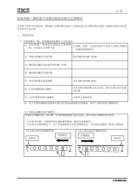
注:由于从塑料薄膜的包装袋中取出的导轨表面附着有防锈油,请用干净的布进行擦拭清洁。
关于导轨安装螺钉的拧紧顺序: ※导轨安装螺钉的正式拧紧,以导轨基准面朝上的方向看,按从右到左的顺序进行固定。
・从右依次拧紧,可使滑轨更好地贴紧基准面,能提高安装精度。 ・从左依次拧紧的情况下,会产生使滑轨离开安装基准面的力,是导致安装精度下降很大的原因。
超高精度・超高刚性加长 85、100
自由自合规格
成套品 滑块单件
○
○
○
-
○
○
-
-
○:有添附 非互换性规格
成套品 ○ ○ -
日本东晟株式会社
日本东晟株式会社
④ 楔形块式夹紧方式
4/6
[优点] ・可以确实的用表面压住导轨的侧面。
[缺点] ・侧向压力非常大。因此,如果螺丝拧太紧的话,导
轨会变形。没有必要对侧面固定螺钉做很强的固定。
※注意事项 ・横压的螺钉与导轨安装孔数一样,设置在安装孔的正侧面。 ・要注意侧向压板和侧面固定螺钉等如果拧紧力太大的话,由于压紧导轨的侧面发生弹性变形可 能造成导轨翘起。(下图)
32.0
20.4
M 10 ×1.5
62.7
-
M 12 ×1.75
108
-
M 14 ×2
172
-
M 16 ×2
263
-
M 20 ×2.5
512
-
M 24 ×3
882
-
M 30 ×3.5
1750
-
(4)插入假导轨的添附产品
系列与大小
C-Lube 自润滑圆柱滚子 直线导轨超级 X
圆柱滚子直线导轨超级 X
10~30 35~65
直线导轨说明书
最大工作负荷的计算: ;
寿命L计算: 。
2、摩擦力的计算:
摩擦力 ,其中刮油阻力 ,运动垂直方向负荷 ,摩擦力系数取 ,带入以上数据,得 。
3、注油频率的计算及供油速率的选择:
注油频率 ,供油速率为 。
三、直线导轨的安装
1、清除床台装配面的污物;
2、将直线导轨平稳的放在床台上,并让导轨侧边基准面靠上床台装配面;
3、所有方向皆具有高刚性
运用四列式圆弧沟槽,配合四列钢珠等45°之接触角度,让钢珠达到理想的两点接触构造,能承受来自上下和左右方向的负荷;在必要时可施加预压以提高刚性。
导轨滑块结构如下图所示:
滚动循环结构:滑块、导轨、端盖、钢珠、钢珠保持器等;
润滑系统:油嘴、油管接头;
防尘系统:刮油片、底片尘封防尘片、导轨螺栓盖、金属刮板。
本导轨设计为HG系列直线导轨,相较其他直线导轨,又有பைடு நூலகம்己的特点。
1、自动调心能力
来自圆弧沟槽的DF(45°—45°)组合,在安装时,皆有钢珠的弹性变形及接触点的转移,即使安装面多少有些偏差,也能被先规划快内部吸收,产生自动调心能力之效果而得到高精度稳定的平滑运动。
2、具有互换性
由于对生产制造精度严格管控,直线导轨尺寸能维持在一定的水准内,故导轨滑块具有互换性,可分开储存,以减少储存空间。
刮油片及底面尘封防尘片可阻止加工铁屑或尘粒进入滑块里面,破坏珠道表面而降低直线导轨寿命。上防尘片可有效防止 粉尘从导轨上表面或螺栓孔出进入滑块内部。
六、直线导轨的配置
直线导轨能承受上、下、左、有方向的负荷,因此可根据机台结构与工作负荷方向配置直线导轨组。本导轨采用三支导轨滑块移动外加齿轮齿条啮合配置。其中,导轨与滑块的配置如下图所示。
《直线导轨安装步骤》word版

直线导轨安装步骤:
步骤.1:在安装直线导轨之前必须清除机械安装面的毛边、污物及表面伤痕。
注意: 直线滑轨在正式安装前均涂有防锈油,安装前请用清洗油类将基准面洗净后再安装,通常将防锈油清除后,基准面较容易生锈,所以建议涂抹上黏度较低的主轴用润滑油。
安装步骤.2:将主轨轻轻安置在床台上,使用侧向固定螺丝或其他固定治具使线轨与侧向安装面轻轻贴合。
注意:安装使用前要确认螺丝孔是否吻合,假设底座加工孔不吻合又强行锁紧螺栓,会大大影响到组合精度与使用品质。
安装步骤.3由中央向两侧按顺序将滑轨的定位螺丝稍微旋紧,使轨道与垂直安装面稍微贴合。
顺序是由中央位置开始向两端迫紧可以得到较稳定的精度。
垂直基准面稍微旋紧后,加强侧向基准面的锁紧力,使主轨可以确实贴合侧向基准面。
将所须附件一并安装。
(附件可能为油嘴、油管接头、或是防尘系统等。
)
安装步骤.7先锁紧移动平台上的侧向迫紧螺丝,安装定位后将在依照下列顺序进行
3-3以下为常见的几种安装线性滑轨的模式:
3-4以下为常见的几种固定线性滑轨的模式:
(本资料素材和资料部分来自网络,仅供参考。
请预览后才下载,期待您的好评与关注!)。
直线导轨说明书

4、使用侧向固定螺钉,按顺序将导轨侧边基准面逼近床台侧边装配,以确定导轨位置;
5、使用扭力扳手,以特定扭力按顺序锁紧装配螺丝,将导轨底部基准面逼紧床台底部装配面;
6、依以上步骤安装其余配对导轨。其中,基准导轨采用虎钳夹紧法(如图1所示),从动侧导轨采用移动平台法(如图2所示)。
1、减少滚动部分的摩擦、防止烧伤并降低磨损;
2、在滚动的面与面之间形成油膜,可延长滚动疲劳寿命;
3、防止生锈。
直线导轨在使用前,可封入锂皂基润滑油脂以润滑珠槽滚道,虽然润滑油脂较不易流失,但为避免因润滑损耗造成润滑不足,因而在使用距离达100km时,再补充润滑油一次。润滑油适用于各种负载及速度的场合,但由于润滑油易挥发因而不适用于高温润滑。计算注油频率为83.3h。
二、相关计算
1、直线导轨的寿命计算:
静安全系数 (一般运行状况); 。
直线导轨距离寿命: ,其中硬度系数 ,温度系数 ,负荷系数 (取使用速度v=20m/min);时间寿命: 。
直线导轨的使用规格:HGH35A-CA,基本动额定负荷 ,基本静额定负荷 ,预压 。设备尺寸: , , , 。加工条件:装置本身的重量W=4kN,钻孔作用力F=1kN,系统温度为常温,负荷状态为普通负荷。
刮油片及底面尘封防尘片可阻止加工铁屑或尘粒进入滑块里面,破坏珠道表面而降低直线导轨寿命。上防尘片可有效防止 粉尘从导轨上表面或螺栓孔出进入滑块内部。
六、直线导轨的配置
直线导轨能承受上、下、左、有方向的负荷,因此可根据机台结构与工作负荷方向配置直线导轨组。本导轨采用三支导轨滑块移动外加齿轮齿条啮合配置。其中,导轨与滑块的配置如下图所示。
滚珠丝杠及直线导轨安装方法和调整技巧01[终稿]
![滚珠丝杠及直线导轨安装方法和调整技巧01[终稿]](https://img.taocdn.com/s3/m/371fbeb7294ac850ad02de80d4d8d15abe2300be.png)
滚珠丝杠及直线导轨安装方法和调整技巧01直线导轨长1.7m,工作行程可达1.5m。
导轨工作台是装有两条滚动直线导轨,每条导轨上有两个滑块,以保证移动的稳定性。
校直的两个目标:一.基准导轨达的直线度误差达在到规定范围内;二.两条导轨之间的平行度误差达到规定值。
辅助工具:带磁座的千分表和水平仪(2um/200mm)坐标系设定如下图所示:基准在左边,被测导轨在右边,从上向下俯视是测量系统的俯视图,正向视图为测量系统的主视图。
根据使用坐标系习惯,规定系统的俯视图图示所示的方向为X轴方向(水平)的正方向。
在铅锤线上,设定主视图所示向上的方向为Y 轴(铅锤)的正方向。
导轨基准X轴正方向基准线系统俯视图D有正反两种安装,当CCD正装时,测量系统给出的计算结果才与实际相符。
如果反装,则结果与实际方向相反,在修整导轨直线度时要特别注意。
2.视频窗口的坐标是以向右为X轴正向,向下为Y轴正向,原点在视频窗口的中心。
状态栏(右下角)中的中心坐标既是图像中心在视频窗口中的坐标值,单位为像素。
(一) 校直的方案:基准导轨的理论基准直线是空间的直线,因此在两个相互垂直的平面(水平面和铅垂面)分别校直。
校直过程中,直线度误差的测量也是在这两个平面内进行的。
坐标系的设定和测量系统相同。
由于导轨是刚性件,挠度较小,校直幅度不能过大,所以,校直的过程中,直线度误差的计算采用最小二乘法。
在校直的过程中,是以最小二乘中线作为基准直线。
在校两条导轨平行程度时,也是采用最小二乘中线为基准。
导轨和导轨基座的接触是面接触,导轨靠基座上的相互垂直的平面进行定位。
校直中,基座接触面增加材料(垫薄片材料)远比去除材料(磨削或刮研)容易,所以,本校直实例采用增加材料(垫薄片材料),但只能达到数丝的精度(垫薄片材料厚度限制),要达到高的精度则需要用去除材料的方法。
校直过程中的基准直线实际是平行基准导轨最小二乘中线并且通过极限点的直线。
由于以基准导轨最小二乘中线为基准线,为调整方便,选取平行基准线并且通过极限点的直线作为调整的基准,然后计算出各测点相对该调整基准直线的偏移量,按其偏移量进行调整。
直线导轨的安装方法

直线导轨的安装方法
1、直线导轨安装步骤:
(1)准备安装设备:直线导轨、安装支架、定位块;
(2)准备安装场所:平整的基座和安装支架须放置在稳定的地面上,安装时注意防止运动方向上有碰撞;
(3)将安装支架安装在定位块上,并且将安装支架与定位块固定在
稳定的地面上;
(4)安装直线导轨:
a.首先通过调整安装支架上的准备孔,依据直线导轨的长度进行安装;
b.将直线导轨的入口螺纹放入准备好的安装支架;
c.紧固螺母和螺栓对导轨固定;
d.安装好直线导轨后,再次紧固所有被安装的螺栓和螺母,以确保
固定的有效性;
(5)安装完成后,可用检测仪测量直线导轨的精度,使其处于待用
状态;
2、安装中需要注意事项:
(1)直线导轨安装后,记得加上防锈涂料;
(2)导轨安装前需检验安装支架是否有缺陷;
(3)安装场所要保证平整,注意防止运动方向上有碰撞;
(4)安装时要慢,包括安装和拆卸,安装必须有特定人员做操作,
确保安全;
(5)安装完成后需要调整,配合时需要完成定位调整;
(6)不要用重物影响导轨,导轨的使用负荷应尽量低;
(7)直线导轨的安装要和零件的安装配合,千万不可脱离搭配,影响定位;
(8)在安装之前要清洁场所,不要有灰尘、油污及金属碎屑等杂物掺入。
直线导轨安装作业指导书
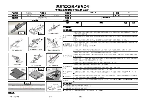
产品名称直线导轨产品型号生效日期页码发行部门品质部执行部门装配部修订日期版 本工位名称文件编号料号名称用量备注5、从动侧导轨安装6、导轨接头7、检验深圳市XXXX技术有限公司2、安装时保证导轨的形状位置公差。
3、导轨安装后,滑块能顺畅滑动,无卡涉现象。
见(图11)变更內容:制作:聂代财 校准: 审核:1、导轨基准面选择2、机械零件安装面基准的选择3、导轨的安装4、承载平台的安装③紧锁装配螺丝将承载平台按对角线顺序紧固在滑块上。
见(图8)以基准侧导轨为基准,用百分表校正从动侧导轨位置使之平行,将落地依次紧固。
平度度≦0.03mm.见(图9)导轨的接头必须按照导轨上的标记来进行安装,以保证直线导轨的精度。
且建议配对的导轨接头位置能够错开。
平面与两侧面形位偏移小于0.03mm。
见(图12)安装完直线导轨后,调整,检验直线导轨的直线度,平行度。
直线度2m≦0.02mm,平行度2m≦0.04mm,见(图9)四.注意事项:1、安装时注意安装手法和螺钉的锁紧方法。
②将导轨平稳地放在零件上,使导轨的基准侧贴紧零件的安装面。
见(图3)③将所有螺栓都装配到安装孔以确认孔距是否准确,按顺序将直线导轨的止动螺丝拧紧,使轨道与横向安装面紧靠。
见(图4/5)④使用扭矩扳手 , 将装配螺栓按规定的扭矩拧紧。
直线导轨装配螺栓的拧紧顺序是,从中央位置开始向轴端部按顺序拧紧,这样可获得稳定的精度。
见(图6)⑤其余的配对直线导轨也按同样的方法安装,直到安装全部完成。
见(图2)①使用装配螺丝将承载平台大概固定于滑块上。
见(图10)②使用固定螺丝,将滑块侧边基准面紧固与平台侧面装配面,以确定装配位置。
①非互换型的直线导轨使用时需要注意基准面和非基准面的差异。
基准侧的精度比非基准侧的精度要高,可作为零件止口的承靠边.②滑块的基准边为精加工的侧边,若两侧边都为精加工面,此滑块为互换型滑块,两侧都可以作为安装的基准边。
③直线导轨的基准边为箭头指向的边,若没有箭头标记则两侧都可以作为基准边。
直线导轨安装步骤

线性滑轨的安装的安装步骤建立线性滑轨良好的使用品质,初步成败条件是需要正确的选用规格型号,但影响使用品质的最后关键因素在于线性滑轨的安装品质,即使选用正确型号的线性滑轨,也容易因为安装品质不良导致大幅度影响产品寿命与机构运作上的表现,而良好安装品质是建立在遵守线性滑轨安装设计原则与安装步骤的基础上,以下是安装线性滑轨应该注意的设计事项与安装步骤事项。
1-1先选取基准轨与从动轨当非呼唤型线性滑轨配对使用时,需注意基准轨与从动轨之差异。
基准轨侧边基准面精度较从动轨高,可作为床台安装承靠面。
基准轨上有刻上MA之记号,如图所示:1-2机床台受到振动及冲击力作用,且要求高钢性、高精度的安装:(1)固定方式:当机床台受到振动、冲击力的作用时,滑轨及滑块很可能偏离原来固定位置,而影响精度。
为避免发生类似的状况,建议使用下图所列的四种固定方式固定滑轨及滑块,以确保机台的运行精度。
(2)滑轨安装1.清除机床台装配面的污物。
2.将线性滑轨平稳的放在机床台上,并让滑轨侧边基准面靠上机床台装配面。
3.试锁装配螺丝以确认螺栓孔是否吻合,并将滑轨底部基准面大概固定于机床台底部装配面。
4.使用侧向固定螺丝钉,安顺序将滑轨侧边基准边基准面逼紧机床台侧边装配面,以确定滑轨位置。
5.使用扭力扳手,以特定扭力按顺序锁紧装配螺丝,将滑轨底部基准面逼紧机床台底部装配。
6.依步骤1至5安装其余配对滑轨。
(3)滑块安装1.使用装配螺丝的滑板大概固定于滑块上。
2.使用固定螺丝,将滑块侧边基准面紧固于滑板侧边装配面上,以确定滑块位置。
3.锁紧装配螺丝将滑板按图所示,按①~④对角线顺序紧固于滑块上。
1-3 线性滑轨安装注意事项1.线性滑轨产品在出货前,均涂布滴量的防锈油,安装使用前请擦拭滑轨的防锈油,才可以移动滑块。
2.确认安装基准面:滑轨基准面位”HIWIN”字样旁箭头所指的侧边平面(B);而滑块基准面则为经过研磨的光滑表面(D)。
3.滑轨接牙件:滑轨接牙安装时必须依照滑轨上表示顺序安装,以确保线性滑轨精度。
NSK线性导轨安装说明说明书
Assembly and Installation of NSK Linear GuidesLinear Guide: Handling PrecautionsNSK linear guides are high quality and are easy to use. NSK places importance onsafety in design. For maximum safety, please follow precautions as outlined below.(1) Lubricationa.Remove the rust preventativerail-coating before installation. If you are using oil as a lubricant, consult NSK for compatibility issues with the pre-packed factory grease.(2) Handlinga.Interchangeable ball slides (randomly matching types between rail and ball slide)are installed to the provisional rail when they leave the factory.Handle the ball slide with care during installation to the rail.b.Do not disassemble the guide unless absolutely necessary.c.Ball slide will move easily. Make sure that the ball slide does not disengage from the rail.d. Standard end cap is made of plasticand may break if a direct force is applied.(3) Precautions in usea.Make every effort not to allow dust and foreign objects to enter.b.The temperature of the place where linear guides are used should not exceed 80˚C (excluding heat-resistant type linear guides.)A highertemperature may damage the plastic end cap.c.If the user cuts the rail, thoroughly remove burrs and sharp edges on the cut surface.d.When hanging upside-down (e.g. the rail is installed upside-down on the ceiling in which the ball slide faces downward),should the end cap be damaged,causing the balls to fall out, the ball slide may be detached from the rail and fall. For such use, take measures including installing a safety device.(4) Storagea.Linear rail may bend if storedinappropriately. Place it on a suitable surface, and store it in a flat position.1Confirm lubrication.Handle with care.Do not drop.Do not disassemble.Do not use direct force.Do not contaminate.Do not hang upside down.Temperature limitation.Store in the correct position.2Thank you for choosing NSK linear guides. This manual briefly describes the recommended handling and installation of NSK linear guides for general industrial use.There are two methods of installing linear guides. The first uses a datum shoulder on the mounting base and provides accurate horizontal alignment in the same way used for machine tools. The other method uses the first rail as a reference for the second rail and is generally used when smooth motion versus high accuracy is required.NSK recommends the interchangeable series LH and LS linear guides for general industrial applications. Their self-aligning feature means a greater tolerance for alignment errors and less time spent on installation. Also, they are interchangeable between rail and slider, easily allowing the addition or replacement of parts.For interchangeable LH and LS Series linear guides, the ball slides and the rails are stocked separately. The ball slides are mounted on plastic provisional rails that allows for easy transfer of the ball slide to and from the steel rail.Provisional rail.Installation ProceduresWhen transferring the ball slide from the provisional rail onto the rail, or vice versa, butt the provisional rail up against the rail and slide the ball slide directly from one onto the other. It is a good idea to secure the ball slide onto theprovisional rail with a rubber band after removal from the rail.The following is a description of how the ball slide should be removed from and replaced on the linear guide rail.The ball slide is held on the provisional rail using a rubber band. The rubber band should catch the bottom channel in the provisional rail and then twist around to secure the ball slide.The ball slides are designed with retaining wires to prevent the balls from falling out when they are removed from the rail. However,NSK recommends that the ball slides should be stored on aprovisional rail prior to installation to prevent contamination from dust and other foreign objects.3Linear guide rail.Provisional rail.If a ball is accidentally droppedcleaned and replaced to theappropriate groove. The correctgroove can be determined by thesize of the clearance between theballs (the groove missing the ballwill have greater clearance thanthe other grooves). It is normalto have a gap of 1.5 balldiameters in each groove.The following section describes how to install the linear guides on the machine.Ball slides and rails are supplied separately. Each is wrapped in vinyl sheet, and packed in a container.an available option for use inhigh contamination areas toprevent debris build-up in thebolt holes which may damagethe slider. Please request theseat time of order.4The rail is always shipped with rust preventive oil, which should be wiped off before use. LH and LS Series ball slides are pre-packed with grease, so no cleaning is required prior to installation.Now the linear guide is ready for installation. Place it carefully on the mounting surface.Then tighten the bolts with a torque wrench to the specified torque starting from one end.In NSK linear guides, the mounting bolt holes are processed after heat treatment using a precision machining center; therefore, the bolt hole pitch accuracy is as good as the positioning accuracy of the machine, which is considered very good.When tightening the bolts, be sure to start at one end and work in order to the other end. If the bolts are tightened at the middle first, it tends to leave the railcurved. If you suspect this has happened, loosen the bolts and start again.5For Smooth Motion of General Machinery Snugly tighten the mounting bolts temporarily so that the rail is firmly against the bed.6The rail that has been tightened can now be used as a reference rail. Using a vernier calipers or other accurate tool, measure the distance between the two rails, and adjust each end until they are the same. Tighten a bolt snugly at each end of the rail.The next step is to install the table, and to use the table to align the rails.Firmly bolt the table to ball slides 1 and 2 on the firmly secured rail as shown in the diagram. Then position ball slide 3 at the left end of the adjusting rail, and bolt the table to this ball slide. Move the ball slide 3 to right and bolt the table to the ball slide 4.Move the table to one end of the rails, and start tightening the adjusting rail bolt sequentially to the specified torque while checking excessive friction of tablemovement. Continue moving the table down the rail tightening each adjacent bolt until they have all been tightened.This method of assembly is for general industrial machinery where smooth linear motion is the overall objective. When precision accuracy is required,read on to the following procedure.For Greater Accuracy ofGeneral MachineryWhen bolting the first rail on themachine base, align it straight usinga straightedge and a dial indicator.Bolt on the rail at the both endslightly, and position a straightedgebeside it. Set the straightedgeparallel to the rail measuringdistance A1 and A2 by a verniercalipers or some other accuratemeasuring tool.Move the dial indicator along the straightedge, and take readings at every bolt hole along the rail. Make fine adjustment of the rail to the straightedge until the desired reading is made, and tighten the bolt to the specified torque.When all of the bolts have been tightened, slide the dial indicator from one end of the rail to the other to ensure that the desired straightness has been achieved.Position the dial indicator on two ballslides on the reference rail as shownin the diagram. Tighten bolts of theadjusting side rail sequentially fromthe one end while noting the readingof the dial indicator.Straightness of NSK linear guidesis controlled so that it can beeasily adjusted manually foreasy installation.During installation, it is recommended that accuracy is checked to ensure smooth operation.78This section describes the allowable tolerances for installation in order to maximize the performance of NSK linear guides.We recommend that the mounting errors e 1or e 2do not exceed the values shown in the table below.If the error readings are equal to or less than the above values, you have correctly assembled the parts. For maximum accuracy, keep the readings below what is shown in the table.If your readings are greater than these values, it is necessary to remove the parts and start over. Please contact your local NSK office with any questions or for assistance. Visit for contact information.Recommended allowable installation error of the LS Series (Maximum) Unit:µmK1™ Handling InstructionsTo maintain the NSK K1™ lubrication unit over a long period of time,please follow these instructions.Ball SlideNSK K1™End (rubber)sealEnd (rubber)sealRail1.Max. operating temperature: 50°C (122°F)Max. peak temperature: 80°C (176°F)If not installed immediately, they should be kept refrigerated.Avoid storage in direct sunlight.2.Never leave the linear guide in close proximity to grease-removing organicsolvents such as hexane, thinners, etc. Never immerse the linear guide in kerosene or rust preventative oils which contain kerosene.NoteOther oils such as: water-based cutting oil, oil-based cutting oil, grease (mineral oil-AS2, ester-PS2) present no problems to the K1™ lubricating units performance.9Assembly Instructions for the K1™Lubricating Unit1.Slide linear bearing on to the linear rail, using the plasticprovisional rail supplied.2.Remove the grease fitting from the end of the bearing.3.Remove the Phillips screws (2 pieces).4.Remove the end lubrication unit from end of bearing.5.For maintenance free operation, install threaded plug; for re-greasingoption, see points 10 & 11 below.6.Install the cover plate from the K1™ lubricating unit kit to the end ofbearing, against the end cap.7.Install K1™ lubricating unit without fixing rings, so it can beexpanded over the rail.8.Put the three (3) fixing rings in position on the K1™ lubricating unit.9.Replace the end seal , in front of the K1™ lubricating unit.10.Install connector screw for grease fitting.11.Replace the grease fitting in connector screw.12.Install the extension Phillips screws (2 pieces, supplied with theK1™ lubricating unit kit).NoteThe K1™ lubricating unit has a shelf life. They should be installed immediately upon receipt. It is important to avoid direct sunlight and extreme heat conditions.40There are two types of lubricating methods –grease and oil –for ball screws and linear guides.Use a lubricant agent and method most suitable to condition requirements and purpose to optimize functions of the ball screws and linear guides.In general, lubricants with low base oil kinematic viscosity are used for high speed operation.Lubrication with high base oil kinematic viscosity is used for oscillating operations, low speed and high temperature.The following are lubrication methods by grease and by oil.Note: Please consult NSK Engineering for grease replenishment interval.Grease LubricationGrease lubrication is widely used because it does not require special oil supply system or piping. Grease lubricants made by NSK are:•Various types of grease in bellowed container which can be instantly attached to the grease pump;• NSK Grease Unit which comprises a hand grease pump and various nozzles. The units are compact and easy to use.NSK grease lubricantsTable 9 shows the marketed general grease widely used for linear guides and ball screws for various applications,conditions and purposes.LubricationTable 9 Grease lubricant for linear guides and ball screwsIntervals of checks and replenishments for grease lubricationFor more info see separate Lubrication InstruktionLG Handbook Printed in Canada © NSK 2005.NSK Ltd. has a basic policy not to export any products or technology designated as controlled items by export-related laws. When exporting the products in thisbr ochur e, the laws of the expor ting countr y must be obser ved. Specifications ar e subject to change without notice and without any obligation on the par t of the manufactur er. Every care has been taken to ensure the accuracy of the data contained in this brochure, but no liability can be accepted for any loss or damage suffered through errors or omissions. We will gratefully acknowledge any additions or corrections.NSK Ltd.-Headquarters, Tokyo, Japan Americas & Europe Department tel: 03-3779-7120Asia Marketing & Sales Department tel: 03-3779-7121AfricaSouth Africa:NSK South Africa (Pty )Ltd.Johannesburgtel: (011)458 3600Asia and OceaniaAustralia:www .au NSK Australia Pty. Ltd.Melbourne tel: (03)9764-8302China:NSK Hong Kong Ltd.Hong Kong tel: 2739-9933Kunshan NSK Co., Ltd.Kunshantel*************Guizhou HS NSK Bearings Co., Ltd.Anshun tel*************NSK (Shanghai )Trading Co., Ltd.Shanghaitel*************NSK representative office Beijing tel: 010-6590-8161NSK representative office Shanghai tel: 21-6209-9051NSK representative office Guangzhou tel: 020-8732-0583NSK representative office Anshun tel*************India:Rane NASTECH Ltd.Chennaitel: 04114-65313, 65314, 65365, 66002NSK representative office Chennai tel: 044-4334732Indonesia:P.T . NSK Bearings Manufacturing Indonesia Jakarta tel: 021-898-0155Korea:NSK Korea Co., Ltd.Seoul tel: 02-3287-0300NSK Korea Co., Ltd., Changwon Plant Changwon tel: 0551-287-6001Malaysia:NSK Bearings (Malaysia )Sdn. Bhd.Kuala Lumpur tel: 03-7958-4396NSK Micro Precision (M )Sdn. Bhd.Kuala Lumpurtel: 03-961-6288New Zealand: NSK New Zealand Ltd.Aucklandtel: (09)276-4992Philippines:NSK representative office Manila tel: 02-759-6246Singapore:NSK International (Singapore )Pte Ltd.Singapore tel: (65)273 0357NSK Singapore (Pte )Ltd.Singapore tel: (65)278 1711Taiwan:T aiwan NSK Precision Co., Ltd.T aipei tel: 02-2591-0656Thailand:NSK Bearings (Thailand )Co., Ltd.Bangkoktel: 02-6412150~58NSK Safety T echnology (Thailand )Co., Ltd.Chonburi tel: (038)214-317-8Siam NASTECH Co., Ltd.Chachoengsaotel: (038)522-343~350EuropeNSK Europe Ltd.(European Headquarters ) Maidenhead, England tel: 0162-850-9800France:NSK France S.A.Paristel: 01 30 57 39 39Germany:NSK Deutschland Gmbh Düsseldorf tel: 02102-481-0NSK Steering Systems Europe Ltd.Stuttgarttel: 0771-79082-277Neuweg Fertigung Gmbh Munderkingen tel: 07393-540Italy:NSK Italia S.P ano tel: 02-995-191Poland:NSK Europe Ltd. Warsaw Liaison Office Warsaw tel: 48-22-645-1525, 1526NSK Iskra S.A.Kielce tel: 48-41-366-6111Spain:NSK Spain S.A.Barcelonatel: 93-575-4041Worldwide Sales OfficesSwitzerland:Waelzlager Industriewerke Bulle AG (W.I.B.)Bulle tel: 026-9191100Turkey:NSK Bearings Middle East Trading Co., Ltd.Istanbultel: 90-216-442-7106United Kingdom:NSK Bearings Europe Ltd.Peterlee, England tel: 0191-586-6111NSK European T echnology Co., Ltd.Ruddington, England tel: 0115-940-5409NSK UK Ltd.Newark, England tel: 0163-660-5123NSK Steering Systems Europe Ltd.Coventry, Englandtel: 024-76-588588North and South AmericaNSK Americas, Inc. (American Headquarters )Ann Arbor, Michigan, U.S.A.tel: 734-913-7500Argentina:NSK Argentina SRLBuenos Airestel: 011-4762-6556Brazil:www.br NSK Brasil Ltda.São Paulotel: 011-3269-4700Canada: NSK Canada Inc.T orontotel: 905-890-0740Mexico:NSK Rodamientos Mexicana, S.A. de C.V .Mexico Citytel: 5-301-2741United States of America: NSK CorporationAnn Arbor, Michigantel: 734-913-7500Sales Offices:Ann Arbor, Michigan tel: 734-913-7500Cerritos, Californiatel: 562-926-2975NSK American T echnical Center Ann Arbor, Michigan tel: 734-913-7500NSK Precision America, Inc.Bloomingdale, Illinoistel: 630-924-8000NASTECHBennington, Vermonttel: 802-442-5448NSK Latin America Miami, Florida tel: (305)477-0605。
导轨安装作业指导书
导轨安装作业指导书一、概述导轨是一种用于支撑和引导物体运动的装置,常见于机械设备中。
它的安装质量直接影响着设备的使用寿命和运行效果。
本文档将介绍导轨的安装作业步骤和注意事项,以确保安装的准确性和稳定性。
二、安装步骤1. 准备工作a. 确认导轨的型号和尺寸,与设备需求相符。
b. 检查导轨和安装所需的附件是否完整,如螺栓、垫片等。
c. 检查安装地面的平整度,确保有足够的承重能力。
d. 准备所需的工具和劳保用品,如扳手、螺丝刀、手套等。
2. 导轨定位a. 根据设备需求,确定导轨的安装位置,并使用水平仪进行水平校准。
b. 标记好导轨的安装孔位,确保与设备连接孔位对应。
3. 安装导轨a. 将导轨放置在安装位置上,并使用丝杠将其固定,以确保稳固。
b. 依次安装螺栓和垫片,注意螺栓的选择和安装力度,确保安装牢固。
c. 如果导轨较长,需要在适当位置添加临时支撑以保持导轨的平整。
4. 导轨校正a. 使用水平仪校准导轨的水平度与垂直度,并根据需要进行微调。
b. 使用测量工具检查导轨的安装精度,如平行度、间距等指标。
5. 导轨端部处理a. 导轨的端部需要进行防腐处理,一般涂抹硅脂或润滑脂以保护表面。
b. 如有需要,可以采用密封或覆盖措施,以防止灰尘和异物进入导轨。
6. 安全检查a. 确保所有的螺栓和连接件已经紧固,无松动现象。
b. 检查导轨的平整度和连接位置是否无误,确保安装质量。
c. 清理安装现场,移除所有的工具和杂物,保持整洁。
三、注意事项1. 在安装导轨之前,务必仔细阅读设备的安装说明书,了解设备所需的导轨型号和尺寸要求。
2. 安装导轨时,需要确保安装地面的平整度,以避免安装后产生不稳定现象。
3. 安装过程中,应按照规定的扭矩要求进行螺栓紧固,以保证连接的牢固性。
4. 导轨的安装位置和孔位需要与设备的连接孔位对应,确保安装正确。
5. 在导轨校正过程中,需要使用准确的测量工具,以确保安装精度。
6. 导轨安装完毕后,请进行安全检查,确保所有连接件牢固,无松动现象。
- 1、下载文档前请自行甄别文档内容的完整性,平台不提供额外的编辑、内容补充、找答案等附加服务。
- 2、"仅部分预览"的文档,不可在线预览部分如存在完整性等问题,可反馈申请退款(可完整预览的文档不适用该条件!)。
- 3、如文档侵犯您的权益,请联系客服反馈,我们会尽快为您处理(人工客服工作时间:9:00-18:30)。
的基准面紧密接触。在重新拧紧导轨上
的螺钉后再将横压板上別的紙螺1钉4 拧紧。即
使 NSK 的导轨有稍微的弯曲,在弯曲的 程度不是太严重的情况下,螺钉就可以 不必拧的过紧。
横压板的作用是保护导轨在意外或 其他情况发生时被损坏。因此,拧紧导 轨的螺钉后再拧紧侧面板的螺钉。
߹㋭ 接下来对另一个 A 表面重复上߹述㋭操 作。 当进行上述测量时,要注意不能移动直
尺。
$ 㸼䴶 $ 㸼䴶
䇗ᭈッ 䇗ᭈッ
\PP \PP
[P [P
从这两个 A 表面的测量数据来确定它
[P
们的平行度。
߹㋭
ޚッ
[P
߹㋭
䇗ޚᭈッッ
[P [P
[PP [PP
24小时销售技术电- 1话1 -:156-9995-6665 网址: 技术QQ:115668417
NSK 的直线导轨的安装孔在热处理后
別紙15
再用精密加工中心进一步的处理,所以
安装空的跨距精度与机器的精度相匹配。
当在有安装基准面或者要在一个平面上
装导轨而没有横压板的情况下,假如不
在这种情况下,直尺务必不能移动。
从这两个测量数据来确定它߹们㋭的 平行
度。
߹㋭
%㸼䴶 %㸼䴶
䇗ᭈッ 䇗ᭈッ
\PP \PP
[[P P
两个 B 表面的测量数据也可以确定它 们的平行度。
߹㋭ ߹㋭
ޚッ ޚッ
䇗ᭈッ 䇗ᭈッ
[P [P
[[P P
\PP \PP
߹㋭ 激光干涉仪可以非常精确地读出水平, 偏转方向的转动以及线性移动。然后由于操 作困难,设置需要大量时间,它并不实用。
鼠أ
ൖⳈ ∈ᑇ
为编写这本手册,我们组合使用直尺、千分表,自准直望远镜以及一个基准面。
߹㋭ 这个基台安装面设计如图,“A”作为导轨
底面,以“B”作为导轨侧面。
其线性和平行度用如下方式测量。
(3) 使用注意事项
(1) 润滑
禁止污染
高温限制
确认润滑方式
a 如果直线导轨在出厂时已经涂抹上了防锈油,请 把导轨上的防锈油擦试干净,在使用前在滑块内 加入润滑剂。
b 如果采用油润滑,滚道的润滑情况取决于直线导 轨的安装方式。在这种情况下,请向 NSK 咨询。
(2) 操作
小心轻放
禁止拆卸
禁止倒置
a 尽可能避免灰尘和异物进入。 b 导轨的使用环境应低于 800C(防热型的直线导
a 可互换性产品的滑块(导轨和滑块可以任意组合) 在出厂时安装在暂用轴上。在把滑块安装到导轨 上的过程中,要始终保持小心谨慎。
b 在没有绝对必要的情况下,尽量避免拆装导轨。 否则会导致灰尘进入更会造成精度的降低。
c 倾斜导轨可能会引起滑块从导轨上滑落。请确认 滑块没有从导轨上脱离。
正确存放 a 如果导轨以不当的方式存放,会引起直线导轨的
螺栓拧转扭矩(材料:SCM) 单位:N·m
螺拧 栓公称型号 紧拧 M2.3 方紧 M2.5 向方 M3
向 M4
拧转扭矩 0.38 0.58
4 4
螺3栓2公称1 型号 3 2M110 M12
1.06
M14
2.5
M16
拧转扭矩 43 76 122 196
M5
5.1
M18
265
M6
8.6
M22
520
M8
22
xμm
x1μm
xμm
24小时销售技术电- 1话2 -:156-99x91μ5m-6665
別紙18
网址:
別紙18
技术QQ:1156y68mm417
导轨会因为与基台的配合而可能变 形。比如,基台有凹陷的话,导轨也会 凹陷下去。所以,测量时要很小心。因 为机器或地面的振动会对导轨产生影响。
$
% % $
测量每个 A 表面的线性度:把一个合适 的测量块放在一个表面,并且把߹千㋭分表的铁 笔放在平行于 A 表面的直尺上,测量块牢固 地贴紧 B 表面。沿着 A 表面按指定的步调滑 动,记录量得的尺寸,接着重复同样的步骤 直到轨道末端。
ޚッ
[P \PP
$ 㸼䴶
24小时销售技术电- 话5 -:156-9995-6665 网址:www.87߹8㋭97.com 技术$ 㸼Q䴶Q:115668417
加选择的由导轨的中间开始安装,导轨
可能会有轻微的弯曲。NSK 推荐的方法是:
保持要安装的平面在安装者的左侧,由
远端向近端顺序安装(如图所示)。这
样的方法可以使螺钉的旋转力就可产生远端
一个压向基准面的力別,紙使1导5 轨与別基紙1准6 面远端
充分贴紧。
別紙15
近端 近端
远端 拧 紧 方 向
近端
4 321
∈ᑇ
߹㋭
24小时销售技术电- 话3 -:156-9995-6665 网址: 技术QQ:1156%68417
对于一些专用测量仪器,必须小心使用并且注意维护保养。 大多数普通的水平仪都是利用液体中 的气泡来进行评判,也有一些是电动式的, 带有一个数字指示器。这两种水平仪都能 用来对垂直和水平的转动进行测量。
別紙9
导轨以及滑块侧面的凹槽指明了基准 別紙9
Hale Waihona Puke 凹面。別紙10
两根导轨看起来相似,但是一个是基 准导轨,其基准面对应于轨道滑別块紙基10准 面可以控制尺寸变化,同时与工作台上 的相应基准面配合。如果其它的滑块靠 着工作台基准面安装。则工作台就会像 如图虚线所示歪斜。在两轴(笛卡尔) 工作平台情况下,不能获得精确的两轴 方形。
通常,工作台上没有为另一根导轨确 定参考安装表面,因此,滑块的表面变 化不会控制的如此严格。这根导轨叫做 “可调整导轨”。
凹
W2
W2
別紙11
6Y-001KL
网2址4小:时ww销w.售87技89术7.电c-o话m9 -:技1术56Q-QL9:Y39591015120-5AL662-66P684Z541 17
用油石或者其它类似石块去除机器安装表 面上的毛刺或粗糙之处。
然后用稀释剂或挥发性液体清洗安装 表面。
有必要对机器安装基面进行精度测量,因此需要用到一些适当的测量仪器。
任何物体的运动都可以分解为߹6㋭个“自 由度”:三个方向的转动(垂直、水平、偏 转)和三个方向的移动(上下、左右、前后)。
ൖⳈ
鼠أ
24小时销22售22 技术电- 1话3 -:156-9995-6665 e1 网址: 技术QQ:115668417 e1
正如以上所说的,直线导轨的安装简单,所以任何人都可以来进行此项作业。
但是,对于 NSK 的直线导轨,如果在安装上出现了误差,就会直接影响到导轨的寿 命,摩擦力会相应的提高。
在普通情况下,利用直尺和千分表或者 电动千分尺,不仅可以测量竖直方向和侧向 的移动,也可以测量垂直、水平和偏转的转 动。
自准直望远镜利用反射光进行转动的 测量,可以对垂直和偏转的转动进行精确 测量。
24小时销售技术电- 话4 -:156-9995-6665 网址: 技术QQ:115668417
基准轨上的KL标志
在导轨的侧面上的生产编号后面有 KL 标志的就是基准轨。
別紙11
LY350120AL2-P4Z1
6Y-001KL
基准轨上的KL标志
导轨的底端在出厂的时候已经涂抹了 防锈油,使用前请用洁净的布将防锈油 擦拭干净。
別紙12 将要安装的导轨放置在基台上。把导 轨的螺钉旋上但暂不拧紧,便导轨的底 端可以紧贴工作台。
24小时销售技术电- 话2 -:156-9995-6665 网址: 技术QQ:115668417
为获得安装经验,在初次安装直线导轨之前,我们建议能够根据以下操作步骤进 行一次试安装。在试安装的过程中,请仔细测量安装面的精度和直线导轨的精度,并 且与要求达到的工作台精度进行比较。在这个过程中,不仅可以对怎样测试相关的精 度有所了解,更能对如何评定机器基台的要求精度和直线导轨的精度等级有所帮助, 从而避免了当机器最终投入批量生产后发生异常情况。在进行直线导轨的初次安装时, 请按照本手册的操作步骤进行。
弯曲变形。所以进行保管的时候,请把导轨放在 水平位置。
d 标准端盖是塑料的,所以敲打或撞击可能会损坏 滑块。
24小时销售技术电- 话1 -:156-9995-6665 网址: 技术QQ:115668417
NSK 直线导轨的安装
〔第一部:机床篇〕
感谢您对 NSK 直线导轨的关注。本部 旨在介绍如何操作 NSK 直线导轨以及如 何以指定的精度将其安装到机床上的步 骤。
如果客户要求轨道安装孔防护盖,则一 并放入。
对于 P3、P4、P5 高精度级别来说,实 际的检测数据会在检测报告中列出。对于 P6、PN 精度级别,检验单按照说明书一并 附上。
24小时销售技术电- 话8 -:156-9995-6665 网址: 技术QQ:115668417
除去塑料纸包装,可看见在直线导轨 的导轨侧面印有产品的型号和生产编号, 在滑块的侧面也印有生产编号。
別紙18
最后,安装好工作台,临时滑台等,
然后检查整机的精度。
19
完成后的整机直线度应该比单独的导
19
轨和滑块要高。
19
然而,这也要考虑到机器的刚性和安
装的精度。每台机器安装时测量到的数
据都是很重要的参数,作为在以后大批
量生产时安装所需的必需数据。
x1μm
xμm
y mm
20 20 20
2211 21
500 500
—
—
別紙17
通过上述步骤安装完导轨后,将金属 滑台装在一根导轨的两个滑块上,和测 量机器底座的基准一別样紙,1用6 同样的方法 测量导轨的垂直方向转別动紙。16
