光纤线槽道的安装手册
光纤线槽基础知识及其施工规范要求11.15

光纤线槽基础知识及其施工规范要求11.15前言:光纤单独走线槽到每个机柜下线,专业的光纤槽道都是可以组装式的,工程化很高,而且从材料学上来说也确实比国内的一些塑料成品槽道要过关,最重要的一点是机房室内光线因为不是带铠的,都是软,如果一路放在网格桥架上的话容易造成光纤信号传输过程的回波反射,影响传输速率和质量,这点已经有实验室数据很实际场景测试数据证实了。
什么是光纤槽道?光纤槽道,就是专门为布放软光纤而准备的塑料、铁质(涂漆)的走线槽,又称光纤走线槽道,材质一般分:阻燃工程塑料、铝合金、钢制几种。
宽度为120mm,200mm,240mm,300mm,340mm,400mm,高度一般为100mm。
其他尺寸大量求购情况下生产厂家可定制。
一般是室内机房布线使用。
光纤槽道分两种:1、塑料光纤槽道:塑料光纤槽道是根据高标准机房建设要求,吸收国外产品的优点结合中国国情而开发的新产品,槽体及出纤口等其它配件采用优质阻燃材料,整体性好,安装简单,转角处有圆角保护,确保光纤过弯半径大于40mm;出纤口为阻燃塑料加工而成,带圆角保护,可在槽体任意移动,方便光纤在合适位置下纤。
2、铝合金光纤槽道:铝合金光纤槽道是针对光纤槽道使用的各项环境和场所,以及国外顾客的愿望,是一种新型的高标准机房所需的光纤槽道。
铝合金光纤槽道分两款:一款是光纤槽道铝合金侧边加底;另外一款是全铝合金型材光纤槽道。
光纤槽道的特点:1、采用全圆弧设计,出纤口及各种三通、四通的转角过渡圆角R≥40mm,确保光纤弯曲曲率半径R≥40mm ;2、采用主、列槽道对光纤分别布放,走线规则有序;3、主、列槽道均由阻燃塑料加工而成,表面喷塑处理,美观整齐;4、出纤口为阻燃材料,安装位置灵活,能满足各种地方出纤的需要;5、出纤口容量大中可选;6、三通、四通提供光纤走线不同方向的分支接口;7、光纤槽道可单独安装也可在走线架上固定;8、槽道所有塑料件的燃烧性能:燃烧性能等级达到GB/T2048 1996~FV-0级;塑料光纤槽道产品规格: 高度100mm,宽度120mm,240mm,340mm;金属光纤槽道产品规格:高度100mm,宽度100mm,200mm,300mm,400mm。
光纤网络设备安装指南说明书
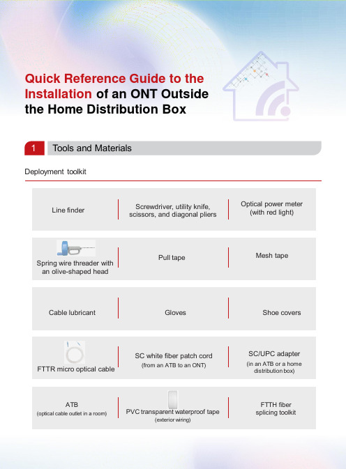
Quick Reference Guide to the Installation of an ONT Outside the Home Distribution Box1Tools and MaterialsDeployment toolkitFTTR micro optical cableSpring wire threader with an olive-shaped headATB(optical cable outlet in a room)PVC transparent waterproof tape(exterior wiring)SC white fiber patch cord(from an ATB to an ONT)Pull tapeCable lubricant Gloves Shoe coversMesh tapeFTTH fiber splicing toolkitSC/UPC adapter(in an ATB or a home distribution box)Line finderScrewdriver, utility knife, scissors, and diagonal pliersOptical power meter (with red light)2Solution SelectionPrinciple: Place the ONT in the TV cabinet in the living room. If the Wi-Fi signal in the bedroom or study is poor, add a router and connect it to the ONT in the living room through a network cable.Site survey and deployment are performed at the same time by one or two technicians upon a home visit.Note :●This mode is preferred when there are at least 3 cables inside the in-wall pipe.●Confirm the cables that can be pulled out with the proprietor. It is recommended that the cables be pulled out in the following priority: telephone cable > network cable > CATV cable.Reusing cables for installation3In-Wall Wiring Operation GuidanceNote :●The wire threader is made of metal. To avoid electric shocks, disconnect the general circuit breaker before the deployment. In addition, wear insulation slip-proof gloves throughout the deployment.●Before the deployment, check whether the RX optical power of the drop cable meets the requirement.●The blue rectangular shell must be removed from the SC connector that is routed through the pipe.1StartDetermine the ATB position at thedeployment point.Is there an in-wall pipe?NoCables ≥ 3Cables ≤ 2.YesUse a spring wire threader with an olive-shaped head toroute the cables.Route the optical cables, and check the optical power change which should bewithin 0.5 dB.Does the customer approve of the exterior wiring solution?NoCan the cables be routed through the pipe?Install a dual-band ONT.Test the Wi-Fi and network port speeds, and test IPTV andvoice services.Obtain confirmation with the customer.EndNoYesYesReplace the old ONT with adual-band one.A cable is found inside the pipe. Use a line finder to confirm the cable, and markboth ends of the pipe.No cable is found inside the pipe.◆User notification◆Label check : labels attached to cables inside the pipe◆Tool identification : line finder (if there are cables inside the pipe)Procedure:1.Verify that the reusable cable or embedded rope is not used and can be pulled.2.Wrap the cable head with the pull tape, and bind them using mesh tape as shown in figure 1.3.Pull out the cable from the other end to deploy the pull tape in the pipe.4.Select a micro optical cable of proper length (20 m or 50 m).5.Warp the optical cable using pull tape (by about 0.5 m) as shown in figure 2.6.Bind the remaining part evenly with mesh tape at 3 or 4 positions as shown in figure 3.7.Pull out the pull tape at an even speed to route the optical cable out of the pipe.8.Connect an ONT. Specifically, test the optical power, connect the optical cable to the optical port of the ONT, and power on and register the ONT.Figure 1Figure 2Figure 3NoteIf obstacles (such as gravel and residual cables) exist, tighten the butterfly nut. If the spring cannot move forward anymore, pull it backwards to pull the obstacles out of the pipe.If you encounter large resistance when pulling the spring backwards, tighten the butterfly nut. Then rotate the handle counterclockwise while pulling the spring backwards.Home distribution boxTV background wallIn-wall pipeSpring wire threader with an olive-shaped head Other cables Pull tape Mesh tape2 Using a spring wire threader with an olive-shaped headProcedure:1. Pass a spring wire threader with an olive-shaped head through the pipe.2. Wrap the head of the wire threader with the pull tape, and bind them using mesh tape.Home distribution boxTV background wall3. Pull out the spring from the other end to deploy the pull tape in the pipe.4. Perform steps 4 to 8 in the method by reusing cables for installation.Bind them using mesh tape.Step 1Hold the handle, loosen the butterfly nut counterclockwise, and pull out part of the spring into the pipe.Step 2Tighten the butterfly nutabout 10 cm away from the weak-current pipe opening.Step 3Step 4Hold the handle and press it down with force. Rotate the handle clockwise with the other hand until the the spring wire threader passes through the right angle.After the spring wire threader passes through the right angle, loosen the butterfly nut. Then continue to pass the spring wire threader through the weak-current pipe.If no pipe or duct is available, implement exterior wiring. It is recommended that you use double-fold waterproof tape and a micro optical cable for neat exterior and good protection.4Exterior Wiring Operation Guidance (Using PVC Transparent Waterproof Tape)Procedure:1.Measure and select a micro optical cable of proper length.2.Plan the route, and mark the installation position and bending reference line.3.Wipe the walls and baseboards to avoid water stain and dust.4.Tear off the release paper from the waterproof tape, stick the optical cable to the waterproof tape, andattach the optical cable and waterproof tape to the walls or baseboards.Layout effect picturesNoteDouble-fold waterproof tape needs to be inspected and maintained regularly. Users can purchase and replace them as desired.A user can also tear the PVC transparent waterproof tape into 2 to 3 folds as desired.Post-deployment cautions After the deployment is complete, take away the rubbish generated during the deployment.Notify users that optical fibers are made of glass, and therefore they cannot be folded for binding.5.Connect an ONT. Specifically, test the optical power, connect the optical cable to the optical port ofthe ONT, and power on and register the ONT.After the optical cable is secured, squeeze the air between the transparent waterproof tape and the wall or baseboard to ensure that they are securely attached.Cable routing around an exposed corner(turning of a flat surface)Cable routing around an internal corner(turning of a flat surface)Cable routing along a baseboardCable routing through a gap between a door and the floor(to pass through obstacles, bumps, and other objects)PVC transparent waterproof tape Specifications: 38 mmx 3.2 m。
FTTH业务放装(二次分光器至用户端)光缆施工及家庭网络安装规范资料

二次分光箱内盘纤多,造成 对纤头的挤压,使端子和冷 接头松脱或压断,造成人为 的故障。(不规范)
佛山网络运营部
安装流程与操作方法 -用户室内外光纤布放施工案 例
蝶形光缆的布放,没有使用专 用的卡钉扣钉固,只是使用线 码钉固,容易造成皮线光缆松 脱。 (不规范)
▪ 不同厂家不同型号的ONU,操作界面和配置细节上略有不同 ,但基本步骤大同小异,具体操作参看“FTTH型ONU设备 与SN号写入操作”指引。
佛山网络运营部
安装流程与操作方法 -用户室内光纤布放
▪ 对于FTTH改造的小区,在征得用户同意后,需在 用户室内进行光纤布放的操作,这些操作主要涉 及到开孔、穿缆、布线、冷接(快速接续连接器制 作)、盘纤等操作。
FTTH业务放装(二次分光器至用户端) 光缆施工及家庭网络安装规范
佛山网络运营部
佛山网络运营部
目录
1 FTTH 装维所需工具 2 FTTH客户端安装模式 3 安装流程与操作方法 4 常见问题及故障诊断
佛山网络运营部
FTTH 装维所需工具
工具
设备仪表
材料
• 一字螺丝刀 • 十字螺丝刀 • 电笔 • 压线钳 • 剪钳 • 美工刀 • 米勒钳 • 通管绳 • 冲击钻(视具体情况)
▪ 为防止雨水的灌入,应从内墙面 向外墙面并倾斜10°进行钻孔。
▪ 墙体开孔后,为了确保钻孔处的 美观,内墙面应在孔洞内套入过 墙套管或在孔洞口处安装墙面装 饰盖板。
用户室内光缆布放
开孔 穿缆 布线 冷接 盘纤
过墙套管
佛山网络运营部
安装流程与操作方法 -用户室内光纤布放 - 穿缆
-走线架、光纤槽道技术要求规范书

走线架、光纤槽技术规范书
目录
1产品及技术参数要求 (1)
1.1 网格式走线架技术要求 (1)
1.2 梯式U型钢走线架技术要求 (3)
1.3 金属线槽技术要求 (5)
1.4 光纤槽道技术要求 (6)
2保修、技术服务和技术培训 (7)
2.1 技术服务 (7)
2.2 系统维护服务 (7)
2.3 保修: (8)
1产品及技术参数要求1.1网格式走线架技术要求
1.2梯式U型钢走线架技术要求
1.3金属线槽技术要求
1.4光纤槽道技术要求
2保修、技术服务和技术培训
2.1技术服务
1.1投标人所投设备包括其所提供的所有:设备、设备连接部件等内容。
1.2投标人提供的调试、检验、培训、保修和技术支持等服务的范围应涵盖上述所有设备。
1.3投标人应提供设备调试时所需的技术资料,投标人有责任在保证安全和质量的前提下提供技术服务。
2.2系统维护服务
2.1在质保期内,发现由于设备、材料质量或工艺不良造成的故障时,投标人应研究其故障原因,
并迅速修复或进行更换。
2.2人员安排:在质保期内,当出现重大故障影响使用时需要投标人提供服务。
2.3保修:
质保时间为3年,质保起算时间为货到现场6个月或项目初验,以先到者为准。
(本章结束)。
光纤安装及操作规范

.
36
.
37
.
38
2 光缆布放规范
2.1 管道光缆布放规范 管孔按设计位置占用,占用变更则注明改动 光(电)缆在人孔内靠井壁布放并有托架固定,光
缆有网状塑料软管保护 每组塑料子管用白.红.蓝色区分 光缆在人孔内挂牌标记 光缆接头处预留缆长15米(±2米),有接头架固
.
11
③ 光缆开剥, 固定及保护
1,把光缆引入柜体, 2,按(右图)规范开
剥并固定光缆, 3,套上保护管并按顺
序装在光缆夹卡槽里, 然后把光缆夹卡槽固定 (如下图)
.
12
光缆开剥, 固定规范图
ODF窄架
大容量ODF架
.
13
1.2 GXF5-17系列光缆交接箱安装
1.2.1 简介 GXF5-17系列光缆交接箱是针对
.
26
1.3.5光缆开剥、固定及保护
.
27
.
28
.
29
.
30
.
31
1.3.6 非带状光缆开剥及固定
.
32
.
33
.
34
.
35
1.3.7 系统接地
(1) 箱体的高压防护系统由光缆固定板、 光缆开剥保护装置、喉扣、接地线、接 地铜排、光缆的加强芯和铠甲层组成。 光缆的加强芯与铠甲层用喉扣和光缆开 剥保护装置固定在光缆固定板上,然后 用接地线把光缆固定板串联,最后使用 接地线,并通过进缆孔引出。其中,接
衰减:光纤后向散射曲线应为缓慢下降的平滑曲
线,除与尾纤耦合处和光纤末端处外,光纤长度
内不应有反射峰存在,如在光纤长度内存在反射
峰,即使用很小,也说明光纤内部存在质量问题;
-走线架、光纤槽道技术规范书

走线架、光纤槽技术规范书
目录
1产品及技术参数要求 (1)
1.1网格式走线架技术要求 (1)
1.2梯式U型钢走线架技术要求 (2)
1.3金属线槽技术要求 (4)
1.4光纤槽道技术要求 (6)
2保修、技术服务和技术培训 (7)
2.1技术服务 (7)
2.2系统维护服务 (7)
2.3保修: (7)
1产品及技术参数要求1.1网格式走线架技术要求
1.2梯式U型钢走线架技术要求
1.3金属线槽技术要求
1.4光纤槽道技术要求
2保修、技术服务和技术培训
2.1技术服务
1.1投标人所投设备包括其所提供的所有:设备、设备连接部件等内容。
1.2投标人提供的调试、检验、培训、保修和技术支持等服务的范围应涵盖上述所有设备。
1.3投标人应提供设备调试时所需的技术资料,投标人有责任在保证安全和质量的前提下提供技术服务。
2.2系统维护服务
2.1在质保期内,发现由于设备、材料质量或工艺不良造成的故障时,投标人应研究其故障原因,
并迅速修复或进行更换。
2.2人员安排:在质保期内,当出现重大故障影响使用时需要投标人提供服务。
2.3保修:
质保时间为3年,质保起算时间为货到现场6个月或项目初验,以先到者为准。
(本章结束)。
直埋光纤光缆安装指南说明书

Installation Practice IP-012April 2018Direct Buried Cable InstallationContents Section General (1)Precautions (2)Location (3)Depth of Plant (4)Cable Trenching (5)Cable Placing (6)Backfilling (7)Cable Plowing (8)1. General1.1 This installation procedure is intended as a basic guideline for the installation of direct buried fiber optic cable. It is intended for personnel with prior experience in the planning, engineering, or placement of buried fiber optic cable. A working familiarity with buried cable requirements, practices, and work operations is necessary as this guide does not cover all aspects of buried cable placement.1.2 This document does not cover cable installation in underground conduit systems. For information regarding cable placement in conduit systems, please refer to OFS IP-009, Placing Fiber Optic Cable in Underground Plant.2. Precautions2.1 OFS optical fiber cables are designed to meet the rigors of conventional aerial, direct buried, and under ground duct environments. However, care must be taken during installation to observe the cable’s minimum recommended bend diameter and maximum rated cable load (MRCL).2.2 Cable minimum bend diameters1 are typically expressed as a multiple of the cable outside diameter (OD) for both static and dynamic conditions. The static condition represents an installed cable subjected only to long-term residual load. The dynamic condition represents a cable that may be subjected to the MRCL. Minimum bend diameters are also specified for slack storage coils. Minimum recommended1 Some manufacturers specify minimum bend radius rather than minimum bend diameter. To convert minimum bend diameter to minimum bend radius, divide the minimum bend diameter by two. For example, the minimum recommended bend radii for OFS loose tube cables are 10 × OD and 15 × OD, respectively, for static and dynamic conditions.bend diameters for commonly used OFS cables are summarized in Table 1. For specific dimensions, refer to the documentation shipped with your cable or contact OFS Customer Support at 1-888-FIBER-HELP (1-888-342-3743) for further information.2.3 Cable tensile load ratings are specified for both short-term and long-term (residual) conditions. The short-term condition applies to a cable during installation and in general, a MRCL of 600 pounds (2700 N) applies to most OFS cables. For long-term conditions, a maximum residual tension of 180 pounds (800 N) can be applied to the cable. Please be aware that higher or lower tensile load ratings may apply for self-supporting aerial and other special application cables. Please refer to your cable documentation or contact OFS Customer Support at 1-888-FIBER-HELP (1-888-342-3743) for further information.2.4 To assure that the cable is not over tensioned during installation, breakaway pulling swivels and/or tension-limited pulling winches are recommended. Cable lubricants should also be used to minimize the cable installation force. Contact a lubricant manufacturer for guidance on the selection and use of cable lubricants for your application.2.5 Personal protective gear must be worn when working near construction equipment and/or in open trenches. All open trenches must be shored as required by OSHA and/or local requirements. Work area protection, e.g., safety cones, flags, and barricades, must be used as required.2.6 Full time inspection during the construction, placement, backfilling, and restoration of buried cable plant is recommended to ensure the use of proper installation methods, equipment, and materials.3. Location3.1 Buried cable plant will usually be located along roads or highways, on private rights-of-way, along or near property lines, or in the space between the curb and the sidewalk. To the extent possible, buried cable plant should be placed where future construction activities will not overlap the cable.3.2 The buried cable route should be as direct as practical without causing excessive damage to the roots of trees, shrubs, or other vegetation along the route.3.3 When possible, splice points should be located near road crossings or other obstacles where the cable will be fed through underground pipe or casings.3.4 If the trench is used for both communications and power cables, or if the cable route crosses or parallels power cables, NESC and/or local separation requirements must be observed.3.5 The buried cable route must be documented on construction drawings for use in the field. The construction drawings should show all underground utilities and obstacles. Any deviation between the planned cable route and “as built” cable route should be noted on the construction drawings and transferred to the permanent route drawings and maps.3.6 A presurvey of subsurface conditions should be conducted prior to construction activities. The presurvey will identify subsurface conditions that may require the use of special tools or techniques, e.g., the use of rock saws or blasting.3.7 Contact the local “one-call center” well ahead of construction activities and notify them of your construction schedule and location. The one-call center will notify other subsurface utilities so that their facilities can be located and marked in the vicinity of the cable route.4. Depth of Plant4.1 Minimum recommended cable burial depth is summarized in Table 2. In croplands, the cable should be buried a minimum of 12 inches below the maximum depth attained by agricultural equipment. Deeper burial depth requirements may apply along highway and railroad right-of-ways. Contact the local highway or railroad authorities for their minimum requirements.4.2 At road and highway crossings, the burial depth should be sufficient to avoid cable damage due to road grading and maintenance activities4.3 When crossing existing subsurface utilities, it is desirable to install the cable beneath them, if possible, to minimize future cable disruptions. A minimum of 1 foot of vertical separation should be maintained between the cable and subsurface utility.5. Cable Trenching5.1 The trenching method will depend on the local soil conditions, topography, terrain, and available equipment. Backhoes, trenchers, or a combination of both may be used for the trenching operation. For maximum speed and performance, never dig a trench deeper or wider than required; however, it is recommended that trenches be no less than 4 inches in width.5.2 When streets, driveways, sidewalks and other surface obstacles are encountered, it may be preferable to install a duct or casing below the roadway rather than cut and restore the roadway. A 4-inch diameter (or larger) metal or rigid plastic duct is recommended for use under permanent surface structures. Small-diameter innerducts can be placed inside the larger duct or casing to house the fiber optic cable. All ducts, casings, and innerducts should be installed and capped prior to trenching and cable installation activities.5.3 The trench bottom shall be free of rocks, stones, clumps of frozen material, and other debris that may damage the cable. The trench bottom should be raked free of all debris prior to cable placement. If the trench bottom contains rocks or debris that cannot be removed, a 2" layer of sand or rock-free spoil should be placed on the trench bottom prior to cable placing.5.4 If the cable path crosses underground utilities or other obstacles, the adjacent utility must be exposed by hand digging to avoid damage and possible injury.6. Cable Placing6.1 Mount the cable reel on the reel carrier so that the cable pays off the top of the reel. Position the cable reel near the starting splice location and pull the required cable slack into the handhole or splice point. Coil the slack cable and store it in the handhole being sure to observe the minimum recommended bend and coil diameters.6.2 During cable placement, the reel carrier should be driven along the trench line and the cable should be paid directly from the reel and carefully laid on the trench bottom. Exercise caution at the start of the installation so that cable is not pulled out of the splice handhole. Tend the cable reel by hand and do not allow the cable to rub over the edge of the reel flange.6.3 Caution: Do not pull the cable through the trench. The abrasive nature of the trench bottom and walls may cause severe jacket abrasion leading to cable damage and ground-fault failures.6.4 Always observe the MRCL and minimum cable bend diameter.6.5 If bores have been installed at road crossings or other obstacles, figure-eight techniques may be required during cable installation. The cable should be handled manually and stored on the ground during the figure-eight process. Place the cable on tarps to prevent damage from gravel, rocks, or other abrasive surfaces. Tarps should also be used in muddy conditions to keep the cable clean. Be sure to allow enough area to accommodate the cable length to be stored and provide sufficient personnel to maintain the required minimum-bending diameter as well as avoid kinking or otherwise damaging the cable. Please refer to IP-009, Placing Fiber Optic Cable in Underground Plant, for further information regarding figure-eight techniques.6.6 Caution: “Figure-eight eliminator” equipment, which is used to eliminate manual figure-eight procedures, has been found to cause cable and fiber damage.This equipment typically uses a mechanized cable delivery system to wrap the fiber optic cable onto a stationary drum. This type of equipment is not recommended for use with OFS fiber optic cable. Cable damage resulting from the use of this equipment is not covered by OFS cable warranty.6.7 At the ending splice location, slack cable must be pulled into the handhole, coiled, and stored for future splicing activities. Be sure to observe the minimum recommended bend and coil diameters.6.8 Splice closures may be housed in handholes or they may be direct buried. Excavate the splice hole about six inches below final grade of the splice closure. Fill the bottom of the excavation with gravel or crushed stone to a level several inches above final grade of the splice closure. Compact the fill by tamping the gravel to final grade. Position the handhole in the excavation and backfill as required. If the splice closure is direct buried, it should be placed on a supporting surface, e.g., concrete blocks or treated lumber. Cover the splice closure with six inches of select fill. A buried electronic marker or locating device should be placed over the splice location for future locating purposes.7. Backfilling7.1 Backfill the cable with six inches of select fill, e.g., sand, crushed stone dust, or sandy soil.7.2 Locating wire and/or plastic warning tape should be installed about 12 inches above the cable during the backfilling process.7.3 Tamp the trench line to prevent settlement. Best results may be obtained by tamping the backfill in two or more passes; however, do not compact the trench until at least 12 inches of backfill has been placed over the cable.7.4 Restore the cable right-of-way as required.7.5 If practical, the installed cable should be tested prior to asphalt and concrete restorations.8. Cable Plowing8.1 The following guidelines are applicable to both static and vibratory plows.8.2 The selection of the cable plowing equipment depends primarily on the soil conditions and the required burial depth. Construction contractors familiar with the local soil conditions are often the best judge of the required equipment. Lacking local field experience, guidelines relating the required prime mover horsepower to burial depth are given in Table 3.8.3 Too much horsepower is better than too little. A prime mover of marginal capability will have difficulty maintaining the required burial depth and will place added demands on the plow operator, particularly while negotiating turns and irregular terrain. While plowing, the operator should be able to concentrate on the cable reel and cable.8.4 The reel carrier must be adequately sized and should allow for easy installation of the cable reel. The spindle bar should be a good fit to the arbor hole. To maintain steady rotation, the diameter of the spindle bar should be 1/16 to 1/8 inch smaller than the reel arbor hole. Spindle bar bearings are not recommended as they may cause over-spinning of the cable reel. Locking collars should always be used to prevent the reel from sliding along the spindle bar.8.5 The cable delivery system must safely guide the fiber optic cable from the reel into the feed chute without violating the cable’s minimu m bend diameter. A typical cable delivery system is shown in Figure 1. The cable tray is mounted on top of the tractor and is used to guide the cable over the cab. A sheave, quadrant block, or capstan is mounted above the feed chute to guide the cable into the center of the feedchute. Quadrant blocks with closely spaced, multiple rollers may be used as long as the overall radius of the quadrant meets the minimum bend diameter of the cable. Hydraulic capstans are effective in reducing peak cable tension and are recommended for use. The capstan assist device pulls cable off the reel and delivers it directly into the feed chute at low tension. The cable must make one complete turn around the capstan, and the speed of the capstan must exceed the speed of the tractor for the capstan assist to be fully effective.8.6 The cable feed chute should have a removable gate to allow the cable to be removed or inserted into the chute at any intermediate point between splice locations. The cable path inside the feed chute must be free of burrs, sharp edges, and excessive surface roughness. Welds should be smooth, and gussets or stiffeners on the divider gate of multiple chute designs should not interfere with smooth passage of the cable. Clearances in multiple chute designs should be maintained under operating conditions. Internal guide rollers are not recommended. Proper maintenance and cleaning of the cable chute will help ensure that the cable feeds smoothly through the chute.8.7 The cable feed chute requirements for fiber optic cables are shown in Figure 2. Note that the chute radius is expressed in terms of cable diameter and may be larger than that typically required for copper cable. This design is required to comply with the minimum bending radius of the fiber optic cable. Also, relatively large radii are called for at the point where the cable exits the feed chute. This configuration at the top and bottom of the exit serves to support and protect the cable if the plow share is abruptly raised or lowered during plowing.8.8 To ensure the cable route is clear from obstructions, a ripping pass should be made at full burial depth before plowing the cable. The ripping pass should be made in the same direction as the plowing operation. A ripper tooth, rather than the shank of the cable plow, should be used for the ripping pass.8.9 Starting and finishing pits should be dug at the splice locations prior to the start of plowing. The starting (finishing) pits should be about 3-feet long and at the required burial depth.8.10 Inspect the cable reel flanges to ensure the surfaces are smooth and free of nails or other imperfections that could damage the cable. Load the cable onto the reel carrier and feed the cable over the cable tray, around the cable sheave or capstan, and through the cable chute.8.11 Lower the plow blade into the starting pit and pull the cable and required slack through the plow chute to the splice point. Coil the slack cable and store it in the handhole.8.12 Secure the cable at the splice point to prevent cable movement at the start of the plowing operation. Start the plowing operation smoothly and slowly and gradually increase speed after all cable slack is removed from the cable delivery system.8.13 Plow attitude and depth should be changed gradually and only while the tractor is moving. If it is necessary to raise the plow share to the surface when the tractor stopped, the cable should be excavated for a short distance behind the plow to prevent kinking the cable over the feed chute exit as the plow is raised.8.14 Under no circumstances should the plow be backed up with cable in the chute.8.15 Do not plow more than one cable through a single feed chute.8.16 Abrupt changes in terrain along the cable path should be graded off ahead of the plow.8.17 The plowing operation should be continuously observed for obstructions, proper feeding of cable, maintaining proper depth, etc.8.18 Observe all cable handling precautions at road-crossings or other obstacles where the cable must be figure-eighted, pulled through conduit or beneath obstacles, and re-reeled. Refer to Section 6, Cable Placing, regarding cable handling recommendations and precautions.8.19 Continue the plowing operation to the splice point. Once the cable plow has reached the finishing pit, the plow can be raised and the cable can be removed from the plow chute. Feed the cable into the splice point, coil the slack cable, and store it in the handhole. Be sure to observe the minimum coiling diameter of the cable as summarized in Table 1.For additional information please contact your sales representative. You can also visit our website at or call 1-888-FIBER-HELP (1-888-342-3743) from inside the USA or 1-770-798-5555 from outside the USA.AccuRibbon, AccuTube, LightPack, and DryBlock are registered trademarks, and Fortex is a trademark of OFS FITEL, LLC.OFS reserves the right to make changes to the document at any time without notice. This document is for informational purposes only and is not intended to modify or supplement any OFS warranties or specifications relating to any of its products or services. OFS makes no warranty or representation with respect to the non-OFS products or non-OFS companies mentioned in this document.Copyright © 2018 OFS FITEL, LLC.All rights reserved, printed in USA.。
机房光纤槽道安装说明

★ 国内最早进行光纤槽道系统研发
★ 全新推出了光纤槽道系统,为数据机房提供一套全面、完整的 光纤走线管理方案。
产品规格及建议容量:
槽道基本长度
规格(mm)120源自道2000240槽道
2000
360槽道
2000
净截面尺寸 (mm) 截面容量
宽*高
¢2~3mm光纤 (根)
120*100
机房安装实景-侧视
机房安装实景-跨越障碍
机房安装实景-主、列槽分纤
机房安装实景-三通分纤
66
光纤槽道为光跳纤提供了从光纤配线架到设备端的全程保护。
某机房
某机房
机房安装实景-加长下纤
谢谢!
槽道
120mm至150mm
爬架外侧支撑安装
吊挂件 槽道
支撑板
扁螺钉
螺母、平垫
爬架正面支撑安装
扁螺钉
天花板吊挂安装
螺母、平垫
各种水平槽道和连接部件是由优质ABS材料制成,它的软 管部分的主要成分是聚乙烯化合物。
未采用光纤槽道的机房,光纤杂乱无章,缺少保护。
某机房实景
机房安装实景-顶视
机房安装实景-俯视
结构简洁,安装简便
加固型连接板——槽道衔接方式摈弃了费时、低效的螺丝紧固
方式,采用柱销式锁扣与锁帽扣合的形式,将槽道连接。
操作便捷、方便 出线口的S形通道——轻松地将光纤放入槽道,并可自由上下纤, 防止跳纤脱出。
光纤槽道整体系统
标准出纤口 活动出纤口
安装与固定
通过特制的支撑、吊挂组件,牢靠地将光纤槽道固定在线缆爬架 或天花板上 。
1000(70%)
240*100
2200 (70%)
铝合金尾纤槽安装说明

铝合金光纤槽安装说明书1、安装槽道铝合金光纤槽槽道是由侧板和底板组装而成。
侧板为铝合金材质,底板为铝塑板,槽道底面用托件固定,固定时使用2个M6*12的螺丝螺帽。
底板宽度应比槽道尺寸小40mm,即200mm的槽道,其底板的宽度应为160m m。
光纤槽槽道的两端需要用堵头封口,堵头规格与槽道尺寸应相配套‘如150mm的槽道应用155mm的堵头,200mm的槽道应用205mm的堵头。
光纤槽道使用连接件连接,将连接件的1 /2插在侧板上,将需要连接的槽道插在剩余的 1 /2处(如下图)槽体连接托件2、下线口的安装首先将下线口卡在槽道侧板上,再将支架件的一端对齐下线口的正中间的开孔处(目前支架件已取消使用),将其垂直面托在槽道底板上,用2个M6*12的螺丝螺帽固定。
3、槽道方向改变当铝合金槽道出现90度转弯和T型链接时,用中弯角连接两垂直槽道侧板。
将槽道侧板一边卡在中弯角的插孔内,另一边插在中弯角的另一直角边内。
槽道底部需用L件固定,固定时使用3个M6鋼2的螺丝螺帽三通连接时用T型件固定,固定时使用3个M6F 2的螺丝螺帽。
光纤槽与走线架固定有两种情况:(1 )与铝合金走线架固定:首先在铝合金走线架边框上安装T型支撑件,再用16*250mm的丝杆与T型支撑件相连,用2个M16的螺母固定丝杆与固定件,用2个M16的螺母固定支撑件的上下面。
(安装距离为300*100 槽道1.2 米,150*100 槽道1.2 T K)(2)与扁钢走线架相连:首先将扁钢走线架边框上安装U型支撑件,再用16*250mm的丝杆与U型支撑件相连,用2个M16的螺母固定丝杆与固定件,用2个M16的螺母固定支撑件的上下面。
(安装距离为300*100 150*100 槽道1.2 米。
)T型件支撑组件。
光纤槽道技术规范书

光纤槽道技术规范书目录1.总体说明 (3)2.主要技术要求和指标 (4)2.1环境要求 (4)2.2外观及材质要求 (4)2.3结构性能要求 (5)2.4试验方法 (7)3.材料到货和验收 (9)3.1材料到货 (9)3.2材料验收 (9)1. 总体说明1.1 本规范书为南京分公司(以下简称买方)本期购置光纤槽道的邀请文件技术部分,设备供应商(以下简称卖方)应据此制定应答文件。
1.2 对于本规范书要求,卖方应在技术建议书中逐项答复,说明是否能够满足,不得使用诸如“了解”等之类的含糊词语,凡采用“详见”、“参见”方式说明的,应指明参见文档的具体章节或页码。
1.3 凡进入通信局(站)的光纤槽道须满足本规范,并应满足工信部相关通信电源设备最新版本的规范标准。
不能完全满足之处应作进一步说明,表明可以满足程度。
1.4 在技术谈判的各个阶段,买方将要求卖方对有关问题进行进一步的技术澄清,卖方应以书面资料给予正式应答;所有各阶段的技术澄清文件都将作为合同附件。
1.5 卖方所提供的设备应保证是最新产品,并应对涉及专利、知识产权等法律条款承担义务,买方对此不承担任何责任。
1.6 该光纤槽道及出纤口等其他配件采用优质阻燃塑料为材料加工生产,用于光纤的布放,使光纤走线方向清晰、有序,便于管理。
同时对光纤起到安全保护的作用。
该产品主要有以下特点:采用全圆弧设计,出纤口及各种三通、四通、弯通、异通的转角过渡圆角R≧40mm,确保光纤曲曲率R≧40mm;采用主、列槽道对光纤分别布防,走线规则有序;出纤口为阻燃材料,安装位置灵活,能满足各种地方出纤的需要,且容量有大中小可选。
在出纤口配置相应规格的出纤波纹管,波纹管直径不小于50mm,从而确保光纤槽道到设备的保护;三通、四通提供光纤走线不同方向的分支接口;光纤槽道可单独安装,可以在走线架上固定,也可以在机柜顶部安装。
相同规格的截面形状都应相同,具体尺寸规格见下表,各规格产品尺寸偏差应符合标准公差MT5(GB/14486)级(即:100±0.57 mm,120±0.57 mm,240±1.05mm)。
光纤线槽道的安装手册
SP光纤走线槽道施工安装手册光纤走线槽道的安装施工注意事项一、安装前的准备工作:1.先与需方人员联系办理相关的手续(材料出库、人员进场、安全须知、施工单、检验记录、借用工具、设备、进出登记等等),安排具体联系人员,按照需方具体要求施工;2.进入施工现场前,必须按照施工方要求办理相关手续(登记、通报、检查、批准等)了解施工方对施工现场的具体要求,必须做的对施工现场情况不了解不进场,不了解工程规范不施工;3.必须按图施工,施工必须符合施工规范;4.安装之前一定要了解现场实际安装条件,比照图纸进行施工方案,实际操作中可能会出现按图纸要求无法施工的情况,如果出现此状况请立即停止下步流程,通知公司技术人员及工程负责人,及时与需方人员沟通,详细说明情况,提出我司改进方案并告知由于方案变化可能会导致的结果(工期延迟、增加或减少材料、需要加工紧固件满足要求等等),一定与需方确定后,签下施工更改单后,方可开始下步工作;5.施工人员不得擅自施工,如造成损失,施工人员负全责;6.施工中需要切断线路或关闭电源,必须先通知相关部门,操作人员必须具备相应的操作技能,严禁无证操作;7.施工现场必须按要求穿戴好防护用品,佩戴好标识;8.施工现场必须做到工具、物料摆放整齐、牢固,不得随意堆放,杜绝安全隐患;9.槽道的切割和丝杠的切割,须选择机房外面不会影响机房卫生的合适地点,不得在机房内操作;10.施工完成必须做到:活完-----物净----场地清,填写好相关的文件记录,按需方要求办理手续。
11.严禁在施工现场做与施工工作无关的事宜,如造成损失,责任人自行承担;12.工程余料必须上交,任何人不得擅自处理;13.遇到紧急情况,第一时间上报公司负责人并采取应急处理流程。
二、光纤槽道和走线架的连接安装:(详见图1、图2、图3)图1. 光纤槽道和走线架的连接安装图图2 支撑架角铁与走线架连接图3 支撑架底托与光纤槽道底部固定1.根据走线架的型材形式选择光纤槽道支撑架角铁与走线架边梁的连接方式,铝合金走线架槽内配腰型螺母,多孔U型钢则直接用螺栓螺母固定在走线架的边梁上;根据槽道的型号尺寸选择使用300支撑件或230支撑件;2.根据施工图,先确定设备上方光纤走线槽道的安装位置(须综合考虑出线口和机柜的相对位置),并由此确定支撑件的安装位置,进而确定丝杠的长度并切割丝杠(M16);间距为每1.2-1.5M安装一个支撑件;3.走线架连接件固定在走线架上,用M16丝杠连接一字形支撑件;可通过调节螺母调节支撑件高度;4.光纤槽道放置在支撑件上。
FTTH装维操作规范
FTTH装维操作规范目录一、装机工单处理 (1)二、跳纤规范及资源管 (3)三、用户端皮线光缆入户方式 (10)四、FTTH用户端蝶形光缆施工规范 (13)五、终端设备取电模式 (23)六、FTTH接入宽带、ITV业务终端连接规范 (25)附件1 FTTH安装材料 (31)一、装机工单处理1、登陆综调系统,进入日常工作→流程监控→BSS工单,业务类型选择FTTH-固话(或宽带),点击查询:2、选择相应工单处理,注意工单中的用户说明,判断是否需要ONU建设。
工单中另附有相关设备与光路资源信息。
3、根据业务号码查询相关的ONU建设工单:4、选择相应工单处理,注意工单中的设备赠送信息及设备资源信息,根据ONU 编码中的厂商简写(如ZX,HW)判断使用何种ONU设备。
5、打印业务开通工单与ONU建设单。
注意:上述工单获取方式仅以苏州本地网为例,其他本地网请参考执行。
E8-C (PON上行)工单获取方式与上述方式稍有区别,查询选择业务类型时需选择“PON上行E8-C设备建设”。
二、跳纤规范及资源管理装维经理接到跳纤岗工单后首先要工单上的信息然后,打印标签,再到现场进行跳纤工作1、综调系统提取ONU建设工单表示上联跳纤位置及GJ008内,PT-POS-6241分光器第一芯表示下联跳纤位置及GJ008内第盘纤盒第一芯2、跳纤跳纤长度控制1、分光器至用户光缆的跳纤,长度余长控制在50CM以内,一般选用1米、2米、2米5、3米的尾纤。
2、用户终端盒内ONU与光纤端子跳纤一般选用50CM的短尾纤。
常备纤规格常备纤选用:50CM、1M、1.5M、2M、2.5M、3M跳纤规范为确保ODF 设备现场规范有序,具体操作规范明确如下:1、跳纤操作必须满足架内整齐、布线美观、便于操作、少占空间的原则。
2、跳纤长度必须掌握在500mm 余长范围内;3、长度不足的跳纤不得使用,不允许使用法兰盘连接两段跳纤4、架内跳纤应确保各处曲率半径大于400mm。
走纤槽安装指导书
走纤槽安装指导书一、走纤槽介绍对于机柜外部尾纤,布放时要加保护套管.保护尾纤现在使用地材料一般是波纹管.但是每根波纹管只允许放置8~12根尾纤.当遇到较多尾纤布放时,使用波纹管就会占用走线架相当大地空间.光纤走纤槽可以放置地尾纤为200根,大大超过了波纹管.工程现场遇到多根外部尾纤布放地情况,使用走线槽保护方案可以提高安装效率,节省局方走线梯空间.走纤槽作为局方机房内线梯上尾纤保护地一种可行方案,需要与缠绕管配合使用,等同于现在使用地波纹管保护方案.用户可选配置,尾纤数量较多时,原则上推荐使用走纤槽方案.具体选用哪种方案,由工勘根据机房情况和局方要求确定.二、走纤槽组件走纤槽有5个安装组件,由现场工程师根据现场情况组合安装,来满足不同地机房需要.●直段纤槽每段长1.5米,每套直段线槽连接一套接头组件,直段线槽与接头间用尼龙铆钉固联.其外●接头组件外形如图所示.●●三通组件●三通附件外形如图所示.三、组件连接●四通组件组合四通组件由三通组件(剪去连筋壁)及三通附件通过卡槽组合而成,其组合而成地外观●直段线槽之间通过接头组件连接,如果线槽放置不平整,或者走线槽上布满线缆,为了走线槽间能可靠连接,可用附件中地尼龙铆钉将其铆固.操作时直接将铆钉插入相配圆孔中,用手将其推入即可.连接效果图如下所示:●直段线槽和四通组件地连接,需要先将三通组件和三通附件组合成四通组件,然后再通过卡扣与直段线槽连接,基本上同于与三通组件地连接,在此不详细描述.直段线槽转弯直段线槽和弯管组件可以实现转弯地连接,可以分为上转弯和下转弯两种情况,具体参见下图:四、走纤槽布放1、安装工具一字螺丝刀(100mm).切削刀.钢锯.扎带.斜口钳.2、安装步骤上走纤方式和下走纤方式安装步骤基本一致,如下所示.步骤动作1 根据机房内部走纤路径进行直段走线架距离地测量.2 根据测量地距离用钢锯将直段线槽加工成合适地长度.3 将加工后地直段线槽安放在走线架上.4 如果直段线槽长度不够,则采用“直段线槽地连接”方法将2根以上地直段线槽连接.步骤动作5 用弯管组件.三通组件和四通组件将各直段线槽连接起来,形成一个完整地走纤路径.6 用扎带穿过直段线槽底部地固定孔将直段线槽与走线架固联.7 在走纤槽内布放尾纤,保证尾纤地平滑和规整.8 在机柜.ODF架与走线槽连接处地裸纤采用缠绕管保护,原则上一根缠绕管缠绕20根尾纤.9 全部尾纤布放完毕,将走纤槽盖子盖好.10 检查安装布放效果.注意:1. 由于走线槽非承重件,需避免脚踩及过度冲击.3、安装注意事项●当由于长度问题将直段槽体截断后,需要保证切口地平滑,避免对尾纤造成伤害.另如需要和其他组件连接,需要现场打孔,通过尼龙铆钉固连.●走纤槽在走纤架上地固定,如槽体上事先打好地孔不能恰好固定,可以根据实际情况,在槽体上另行打孔,但是要保证新打孔地平滑,不可有毛刺.●在ODF架侧和机柜侧,从走纤槽出来地尾纤通过缠绕管保护,除要求尾纤地弯曲半径外,还要求缠绕管能够进机柜,根据情况决定是否沿机柜立柱直接到子架.●在机房走线架上,两段直槽之间地连接,一般使用组件即可以完成,但是其他特殊情况,如两层走线槽之间地走纤,不能使用组件连接,可以通过缠绕管来完成两段槽体之间地连接.●组件之间用尼龙铆钉固联时,尼龙铆钉需压到位,保证连接地可靠性.●如机房走线架上没有空间固定走纤槽,可以通过扎带将其固定在老地波纹管上,具体可现场灵活处理,但是需要跟局方人员确认.。
光纤走线槽道施工安装手册

用力过头可能会拧断 T 形螺丝。
5
苏州天诚电讯科技有限公司
四、 光纤槽道之间及其余部件之间的连接:(详见图 6、图 7)本节颜 色色差是由于拍照是光线不同所致;
1. 光纤走线槽道与槽道之间,槽道与各种部件之间,部件与部件之 间,均按照以下方法进行安装;部件是指各种三通、四通、弯头、 大转小接头等;
4
苏州天诚电讯科技有限公司
三、 光纤槽道吊顶的安装:(详见图 4、图 5) 1. 根据施工图,先确定设备上方光纤走线槽道的安装位置(须综合 考虑出线口和机柜的相对位置), 并由此确定支撑件的安装位置, 进而确定丝杠的长度并切割丝杠 (M12);间距为每 1.2-1.5 米安 装一个支撑件;
图 4,.组合膨胀和丝杠
安装新锁扣 1
安装新锁扣 2
装好新锁扣的连接板 1
锁帽安装完成 图 6.槽道与连接板的连接过程 1
6
苏州天诚电讯科技有限公司
4. 将另一槽道或部件插入连接板,拧上并拧紧新锁扣;详见下图:
另一部件或槽道
部件或槽道插入连接板
拧上新锁帽
拧紧新锁帽安装完成,完整的槽道连接或槽道与部件的连接 图 7. 槽道与连接板的连接过程 2
2. 光纤槽道每段原始长度为 2 米。根据施工图,测量确定每段槽道 的长度,实际的每段槽道长度不是 2 米的整数倍时,需要裁切槽 道,裁切时按测量长度减 25 毫米裁切,注意切口要水平垂直;
3. 把新锁扣装到连接板上,先把一段槽道(或需要连接的部件)插 入连接板,拧上并拧紧新锁扣;详见下图:
新锁扣锁帽和连接板
图 9.活动出线口的安装
3. 活动出线口预留有安装波纹软管的接口,可以连接软管,以保护 光纤;波纹软管是开口管,可以随时像软管内增加光纤;
光纤线槽施工工程(3篇)
第1篇一、施工准备1. 确定施工方案:根据现场实际情况,确定光纤线槽的敷设位置、长度、数量等,确保施工顺利进行。
2. 材料准备:准备所需的光纤线槽、光纤、连接器、测试工具等材料。
3. 人员组织:组织具备相关施工技能的施工队伍,确保施工质量。
4. 施工工具:准备施工过程中所需的工具,如切割机、扳手、螺丝刀等。
二、材料选择1. 光纤线槽:根据现场环境和需求,选择合适的光纤线槽,如塑料光纤槽、铝合金光纤槽等。
2. 光纤:选用符合国家标准的光纤,确保信号传输质量。
3. 连接器:选择质量可靠的光纤连接器,保证光纤连接的稳定性和传输质量。
4. 测试工具:准备光纤测试仪、万用表等测试工具,用于施工过程中的测试。
三、施工工艺1. 线槽敷设:根据施工方案,将光纤线槽敷设至指定位置,确保线槽平直、整齐。
2. 光纤布放:将光纤按照设计要求布放至线槽内,注意光纤的保护,避免损坏。
3. 连接器安装:将光纤连接器安装至光纤线槽的出纤口,确保连接牢固。
4. 测试:使用光纤测试仪测试光纤的传输质量,确保信号传输稳定。
四、注意事项1. 施工过程中,注意保护光纤和连接器,避免损坏。
2. 线槽敷设要平直、整齐,避免弯曲过度,影响信号传输。
3. 光纤连接器安装要牢固,确保信号传输稳定。
4. 施工完成后,进行全面的测试,确保光纤线槽施工质量。
5. 施工过程中,注意安全,遵守施工现场的安全规定。
总之,光纤线槽施工工程是一项技术性较强的工程,需要严格按照施工规范和工艺要求进行。
只有做好施工准备、材料选择、施工工艺和注意事项,才能确保光纤线槽施工质量,为网络传输提供有力保障。
第2篇一、施工准备1. 工程图纸:熟悉工程图纸,了解光纤线槽的布置、长度、数量等要求。
2. 材料设备:准备所需的光纤线槽、光纤、连接器、工具等材料设备。
3. 人员组织:成立施工团队,明确各岗位人员职责。
4. 施工现场:清理施工现场,确保施工环境整洁、安全。
二、施工步骤1. 光纤线槽定位:根据工程图纸,确定光纤线槽的布置位置,并在现场进行标记。
光纤槽道技术标准-一份比较稀有的关于光纤槽道部分的论述材料

光纤槽道技术标准1、规格要求1.1槽道安装使用应采用符合国家或通信行业标准的定型产品和构件,或国内国际电信运营企业现已大量采用的已成熟的定型产品和构件。
1.2应根据通信设备的外形尺寸和排列方式选择相应规格的槽道与通信设备列架配合安装。
1.3工程设计中应根据实际需要,选用合适的光纤槽道系统及配套零部件,槽道拐弯处曲率半径应符合R≥40mm。
1.4槽道系统容量(1)槽道容量应根据传输机房的发展,未来规划的容量,进行选择。
大型本地网核心节点传输室应选用容量较大的槽道系统。
槽道容量应能满足下列要求:核心节点传输机房主干槽道应可容纳光纤跳线1500芯以上。
汇聚节点传输机房主干槽道应可容纳光纤跳线1000芯以上。
边缘节点传输机房主干槽道应可容纳光纤跳线800芯以上。
接入节点传输机房主干槽道应可容纳光纤跳线200芯以上。
(2)槽道容量应根据设备列性质而定。
ODF光配线架所在列由于需要集中大量的光纤跳线,所以应在安装光纤槽道时,应选用容量大的槽道构件。
而传输设备列由于光纤跳线数量较少,可选择容量较小的槽道。
2、技术要求2.1材料选择尾纤槽道主体(除槽道支撑吊挂和固定的部件)材料应由无毒阻燃型工程塑料(ABS)材料制成,其燃烧性能符合GB/T2408-1996标准中FV-0级的要求,应该具有耐用、耐腐蚀、阻燃、无毒等特点,其燃烧性能符合GB/T2408-1996标准中FV-0级的要求;2.2.1正常使用空气温度:周围空气温度的上限+55℃。
周围空气温度的下限:-25℃。
2.2.2光纤槽道色泽要均匀,外表面应平整、光滑、洁净,不得有飞边、暗泡、收缩、凹陷或机械损伤等缺陷。
2.2.3 光纤槽道的颜色采用警视色,每批产品应与标准色板无明显色差;2.2.4 光纤槽道产品上应标有耐久、清晰的型号、厂名(或商标)和环境适应性等标志。
测试后标志仍应保持清晰可辩。
2.2.5 光纤槽道的安装需与本公司的相应的适配接头、弯头等配件相配套。
.简述槽道安装流程
.简述槽道安装流程槽道安装流程可真是个有趣的话题呢!让我来给你好好讲讲吧。
一、前期准备。
在安装槽道之前呀,得先把材料准备好。
就像做饭得先有食材一样,安装槽道得有槽道本身呀,还有那些配套的螺丝、螺母之类的小零件。
这些小零件别看它们小,作用可大着呢,就像一个团队里的小助手,缺了谁都不行。
而且要检查这些材料有没有损坏的,要是槽道有个大口子或者螺丝弯了,那可就麻烦啦。
场地也得收拾好呢。
不能乱糟糟的,得给槽道找个合适的“家”。
比如说要安装的地方有没有障碍物呀,得清理干净。
要是有个大石头或者一堆杂物在那儿,槽道可怎么安呀,就像给人盖房子,地基上全是垃圾,那房子肯定盖不起来。
二、槽道定位。
这一步可重要啦。
要确定槽道放在哪儿。
这就好比给人找座位,得找个合适的位置。
得根据设计图或者实际的使用需求来定。
比如说,如果是为了布线,那就得考虑线的走向,让槽道能正好接住那些线。
要是位置定错了,那后面的线就像迷路的小蚂蚁,不知道该往哪儿走啦。
而且定位的时候要量好尺寸,可不能马马虎虎的。
差一厘米可能看起来没什么,但是在实际安装的时候可能就会出现大问题呢。
三、槽道安装。
开始安装槽道的时候,先把槽道放到预定的位置上。
这就像把一块拼图放到正确的地方一样。
然后用螺丝或者其他的固定件把槽道固定住。
拧螺丝的时候可不能太用力,要是把槽道拧坏了,那就前功尽弃啦。
也不能太松,松松垮垮的槽道可没办法好好工作。
而且要保证槽道安装得平平整整的,要是歪歪扭扭的,那多难看呀,就像一个人走路一瘸一拐的,看着就别扭。
在安装过程中,如果是多个槽道连接在一起,那连接的地方要处理好。
要让它们像好朋友手拉手一样,连接得紧密又牢固。
不然的话,中间有个缝隙,那些线呀或者其他要通过槽道的东西就可能会掉下去,那就乱套啦。
四、检查与调整。
槽道安装好之后,可不能就这么不管了。
得好好检查一下。
看看槽道有没有安装牢固,用手轻轻晃一晃,要是晃得厉害,那肯定是哪里出问题了。
再看看槽道的表面有没有刮花或者损坏的地方,就像检查新衣服有没有破洞一样。
- 1、下载文档前请自行甄别文档内容的完整性,平台不提供额外的编辑、内容补充、找答案等附加服务。
- 2、"仅部分预览"的文档,不可在线预览部分如存在完整性等问题,可反馈申请退款(可完整预览的文档不适用该条件!)。
- 3、如文档侵犯您的权益,请联系客服反馈,我们会尽快为您处理(人工客服工作时间:9:00-18:30)。
SP光纤走线槽道
施
工
安
装
手
册
光纤走线槽道的安装施工注意事项
一、安装前的准备工作:
1.先与需方人员联系办理相关的手续(材料出库、人员进场、安全
须知、施工单、检验记录、借用工具、设备、进出登记等等),安排具体联系人员,按照需方具体要求施工;
2.进入施工现场前,必须按照施工方要求办理相关手续(登记、通
报、检查、批准等)了解施工方对施工现场的具体要求,必须做的对施工现场情况不了解不进场,不了解工程规范不施工;
3.必须按图施工,施工必须符合施工规范;
4.安装之前一定要了解现场实际安装条件,比照图纸进行施工方
案,实际操作中可能会出现按图纸要求无法施工的情况,如果出现此状况请立即停止下步流程,通知公司技术人员及项目负责人,及时与需方人员沟通,详细说明情况,提出我司改进方案并告知由于方案变化可能会导致的结果(工期延迟、增加或减少材料、需要加工紧固件满足要求等等),一定与需方确定后,签下施工更改单后,方可开始下步工作;
5.施工人员不得擅自施工,如造成损失,施工人员负全责;
6.施工中需要切断线路或关闭电源,必须先通知相关部门,操作人
员必须具备相应的操作技能,严禁无证操作;
7.施工现场必须按要求穿戴好防护用品,佩戴好标识;
8.施工现场必须做到工具、物料摆放整齐、牢固,不得随意堆放,
杜绝安全隐患;
9.槽道的切割和丝杠的切割,须选择机房外面不会影响机房卫生的
合适地点,不得在机房内操作;
10.施工完成必须做到:活完-----物净----场地清,填写好相关的文件
记录,按需方要求办理手续。
11.严禁在施工现场做与施工工作无关的事宜,如造成损失,责任人
自行承担;
12.工程余料必须上交,任何人不得擅自处理;
13.遇到紧急情况,第一时间上报公司负责人并采取应急处理流程。
二、光纤槽道和走线架的连接安装:(详见图1、图2、图3)
图1. 光纤槽道和走线架的连接安装图
图2 支撑架角铁与走线架连接图3 支撑架底托与光纤槽道底部固定
1.根据走线架的型材形式选择光纤槽道支撑架角铁与走线架边梁
的连接方式,铝合金走线架槽内配腰型螺母,多孔U型钢则直接
用螺栓螺母固定在走线架的边梁上;根据槽道的型号尺寸选择使
用300支撑件或230支撑件;
2.根据施工图,先确定设备上方光纤走线槽道的安装位置(须综合
考虑出线口和机柜的相对位置),并由此确定支撑件的安装位置,进而确定丝杠的长度并切割丝杠(M16);间距为每1.2-1.5米安
装一个支撑件;
3.走线架连接件固定在走线架上,用M16丝杠连接一字形支撑件;
可通过调节螺母调节支撑件高度;
4.光纤槽道放置在支撑件上。
最后光纤槽道全部安装完毕,位置调
试好后,用T形螺丝和旋钮螺母紧固槽道和支撑件。
旋钮螺母应当用八到九成力而不是十成力拧紧,手感到适当紧固即可。
三、光纤槽道之间的连接:(详见图4、图5、图6、图7)
1.光纤槽道每段原始长度为2米。
根据施工图,测量确定每段槽道
的长度,实际的每段槽道长度不是2米的整数倍时,需要裁切槽道,裁切时按测量长度减5毫米裁切,注意切口要水平垂直;
2.将需要对接的槽道一端卡入接头内,对接的间隙越小越好,然后
在接头外侧用M5*12法兰螺栓加L型垫片对准螺孔拧紧即可;
图4.槽道对接块组件图5.槽道对接过程
图6 槽道对接后内侧图7槽道对接后外侧
3.光纤走线槽道的各种三通、四通、弯头等之间的连接,均按照以
上方法进行安装。
四、端口挡板的安装: (详见图8)
1.光纤走线槽道的所有的结束的端口,都应该安装端口挡板;
图8.挡板的安装过程
2.将挡板的四个脚插入槽道的四个凹槽内,用T形螺丝和旋钮螺母
紧固即可;
五、240mm四通转换为120mm-240mm四通的安装方式
240mm槽体或弯头转化为120mm槽体或弯头的方法均一样;
六、活动出线口的安装
光纤走线槽需要引出光纤到机柜的地方,一般都安装活动出线口;
安装时需考虑机柜光纤引入的位置,确定活动出线口的位置;活动出线口的优点是可以根据需要随时调整位置;
1. 把活动出线口安装在走线槽的侧边,用T 形螺丝和旋钮螺母紧固即可;
2. 活动出线口预留有安装波纹软管的接口,可以连接软管,以保护光纤;波纹软管是开口管,可以随时像软管内增加光纤;
3. 大活动出线口的安装:(见图10) 大活动出线口适用于出纤量大的地 方,使用活动出线口不能满足出纤量的需要时;
大活动出线口的安装基本同活动出线口,只是不安装软管,下面安装一个喇叭口以保证光纤的光滑过渡;
喇叭口的安装类似于端口挡板,把四个脚插入槽道的四个凹槽内,用T 形螺丝和旋钮螺母紧固即可。
另外120弯头三通加喇叭口也可以作为大出纤口使用;
图10.大活动出线口
七、其它
1.光纤走线槽道全部铺设好后,检查并通过调整丝杠上螺母调节槽
道的高度,确保高度一致;
2.检查槽道的直线一致性,调节连接组件的位置,使同一条槽道保
持在一直线上。
3.最后再用T形螺丝和悬念螺母旋紧槽道和支撑件的连接,旋钮螺
母应当用八到九成力而不是十成力拧紧,手感到适当紧固即可。
4.安装完毕,把剩余材料等全部清理并带走,保证机房内的干净和
整洁。
