比利时Traficon VIP-T视频事件检测器
Traficon正式发布无线通讯的Traficam
S
u m a v is io n
”
奖教 金
由S
u m a v
is io
n
每年
出 资3 万 元
.
每 界 奖教
.
金
的评 选 S
u m
a v
jS
Io n
都 会 由公 司 高 层 亲 临 为 获 奖 的 教 师 颁 奖
,
到
目前 为 止 该 奖 已 评 选 颁 发 了 两 届
获 奖 的信 息 工 程 学 院 教 师达 数
维普资讯
幽
“
曰岳
io
”
S
u m a v is
n
奖教 金 助 力 中 国 传 媒 大 学
继
S
u m
2 0 0 6 io
n
年
a V l S
(北 京
数码 视 讯 科 技股 份
有限公 司 ) 与 中国 传媒大学签订 战略 合作协议
、
结成企
.
校协作联 盟 后
S
um a v
2 0 0 7
项
.
。
P e lc
“
o
A P I业 务 拓 展 经 理 T e
0
y
Ca
rv e r
在另
一
篇 新 闻 发 布 中说
,
道 年的
P
e
Ic
充 分 展 现 了 其 对 未来 发展 的前 瞻 力
,
达成其对 系统 序接
.
集 成 及 开 放 的承 诺
口)
.
通 过提供
一
个 明 确 定 义 的A
P I (应 用 程
.
,
因 此 使 用 T r a f ic
智能交通交通事件检测系统方案
浙江大华交通事件检测系统方案ﻬ目录浙江大华交通事件检测系统方案ﻩ错误!未定义书签。
第一章.ﻩ方案需求分析 .............................................................................. 错误!未定义书签。
1.1ﻩ概况ﻩ错误!未定义书签。
浙江大华技术股份有限公司 解决方案部第二章.ﻩ方案特点ﻩ错误!未定义书签。
方案简介ﻩ错误!未定义书签。
方案功能特性ﻩ错误!未定义书签。
检测指标ﻩ错误!未定义书签。
第三章.ﻩ方案架构ﻩ错误!未定义书签。
方案拓扑.............................................................................................. 错误!未定义书签。
3.1.1中心检测方式-方案拓扑.............................................. 错误!未定义书签。
3.1.2前端检测方式-方案拓扑............................................... 错误!未定义书签。
第四章.交通事件检测系统-管理平台介绍ﻩ错误!未定义书签。
管理平台介绍...................................................................................... 错误!未定义书签。
方案总体优势ﻩ错误!未定义书签。
第五章.推荐设备ﻩ错误!未定义书签。
事件检测智能盒-DH-IVS-T3001................................................ 错误!未定义书签。
事件检测服务器-DH-IVS-T7000ﻩ错误!未定义书签。
交通事件检测平台-DSS-T8130...................................................... 错误!未定义书签。
比利时Traficon创飞克智能交通视频事件检测管理系统 FLUX

T RAFICON M ANAGEMENT S YSTEM管理、控制及实时查看交通数据和交通事件图形用户界面,具有强效的事件报警功能及事故过滤功能Flux 是一款智能软件平台,与Traficon 视频检测系统并行应用。
Flux 软件系统收集视频检测器生成的交通数据、 事件、 报警和视频图像序列。
Flux 主要用于管理并监控各种检测器采集的交通信息,将其整理并提供给相关用户。
通过以太网络与视频检测系统进行通信。
Flux 将所有的交通数据、事件及交通报警信息存储于关系型数据库内。
Flux 具有用户友好界面,配备监控和报告功能。
Flux 可实时监控所有事件及报警。
事件信息均自动制成文件并直接显示出来,用户可对每项交通信息进行有效管理。
可同时观看多路摄像机的实时视频。
通过报告功能可查询数据库内信息并创建相关交通数据及事件报告,按图表或表格形式将其导出。
Flux 可定义不同的智能过滤功能确保此系统在特定环境下可进行相关数据统计和事件报警。
(特定环境例如道路维护)Flux 将视频检测系统布局呈现给用户。
定制的图形用户界面帮助视频检测系统直观有效地响应各种交通事件及报警。
Flux 的开放式系统构架确保系统适合于不同项目的具体需求。
重要特征采实时交通数据分析及显示 监控、报警及报告图智同时查看多个摄像机视频流主要优势快便用户友好配置和操作基即可自定义并支持多个不同授权级别用户设置可集开基于浏览器的图形用户界面 (GUI)Flux 客户端界面是以浏览器为基础的应用程序。
用户仅需在客户端PC 上安装网页浏览器,并将此PC 连接至视频检测系统整体网络中,即可使用交通管理系统。
无需在客户端PC 安装任何软件代码,使得基于浏览器设计“零安装”的GUI 界面可向用户提供更加灵活高效的管理能力。
实时交通监控Flux 具有实时事件和交通数据监控功能。
当交通及技术事件发生时,系统会自动显示出事件发生时的当前状态、摄像机图像、所有事件信息和事件发生前后的录像资料。
JJ-VTD-B型视频检测器系统软件设计与实现

收稿 日期 :0 1O —2 2 1 一71 作者简 介 : 王 韬 (9 7) 男 , 1 8一 , 江苏省淮安市人 , 硕士 , 主要从 事智 tafcp rm ee n v n ie ee t r h ewo k sr cu es fwae fa n o sr c:F rJ— rfi aa tra d e e tvd o d tco ,t en t r tu t r ot r rmea d c mmu iain nc t o
p o o o mo g vd o d t c o ,s r e n n g me tc in r t d e .Th mb d e o t r ,s r e o t r n n r tc l a n i e e e t r e v ra d ma a e n l ta e s u id e e e e d d s fwa e e v r s fwa e a d ma — a e e t s fwa ea ed sg e .Th s a h e e n a e n a p id i r fi n t r g ma a e n y tm o a f e r n g m n o t r r e i n d i c iv me th sb e p l t a fcmo i i n g me ts s e f rh l y a ,a d e n o n a
WANG o, QU H u , TANG u i Ta i Yo ln
( h n h i m mu iain c n l g v lp n . S a g a Co nc t sTe h oo y De eo me tCo ,Lt ,S a g a 0 1 5,Ch n ) o d hn h i 0 3 2 ia
BHGE XL Lv VideoProbe 远程视觉检查器说明书

BHGE’s Utility Video BorescopeThe XL Lv VideoProbe from BHGE is equipped to handle a wide variety of remote visual inspection needs.XL Lv VideoProbe*Remote Visual InspectionInsertion Tube Length and Diameter OptionsUtility Packed with FeaturesBHGE’s video borescopes provide one of the best equipment values in the industry.PortabilityOur XL Lv VideoProbe system provides inspectors withunparalleled access—without a bulky base unit. Weighing as little as 1.77 kg (3.90 lb), the XL Lv VideoProbe system can easily “view anywhere.”Image QualityBHGE’s XL Lv borescope utilizes LED illumination to display excellent image quality. You can save clear, accurate still images and motion video to the internal flash memory or removable USB ThumbDrive ™.• 1 GB internal flash memory • 1 USB ® 2.0 port, VGA video out• Full-tip optic interchangeability with secure double threads • Two or four hour Lithium Ion Battery• Lightweight portable design • Still image and live video capture • Full VGA LCD• NEW 4.0 mm optics set for improved image quality and far focus general inspection• Optional automated inspection reporting and data tagging software (Menu Directed Inspection)• Intuitive, easy-to-use controls• Servo motor All-Way* Probe articulation •Shipping and storage case included with systemSystem and AccessoriesOur XL Lv VideoProbe system is supplied in a convenient light-weight shipping/storage case—which protects the system when not in use, and keeps it organized when in use.Magic clamp (optional)Optical tip caseThumbDrive ®Tube gripper (optional)Standard shipping/storage case4 hour battery (optional)Included battery charger/ac adapterTechnical SpecificationsOperating EnvironmentTip Operating Temp:-25°C to 100°C (-13°F to 212°F)Reduced articulation below 0°C (32°F)System Operating Temp: -25°C to 46°C (-13°F to 115°F)LCD requires warm-up period below 0°C (32°F)Storage Temperature: -25°C to 60°C (-13°F to 140°F)Relative Humidity: 95% max, non-condensingWaterproof:Insertion tube and tip to 14.7 psi (1 bar, 10.2 m of H 2O, 33.5 ft of H 2O)SystemCase Dimensions: 48.8 x 38.6 x 18.5 cm (19.2 x 15.2 x7.3 in)System Weight: In Case: 6.50 kg (14.3 lb) Without Case: 1.77 kg (3.90 lb)Power (Lithium Ion Battery): 8.4 V, 38 Wh (2 hour) 8.4 V, 75 Wh (4 hour)Power Supply: AC Input: 100-240 VAC, 50-60 Hz, 1.5 A Max DC Output: 9.5 V, 6.0 A Construction: Polycarbonate housings with integrated Versalon ™(JP)bumpersDimensions: 9.5 x 13.3 x 34.3 cm (3.8 x 5.3 x 13.5 in)LCD Monitor: Integrated transflective 9.40 cm (3.70 in) active matrixVGA color LCD, 640 x 480 resolutionJoystick Control: 360° All-Way Tip articulation, menu access andnavigationButton Set: Access user functions and digital functions Audio: Integrated 2.5 mm headset/microphone jack Internal Memory: 1 GB Flash memory Data I/O Ports: One USB ® 2.0 portVGA Video OutBrightness Control: Auto and Variable Illumination Type: White LED White Balance: Factory default or user defined Long Exposure: Auto and ManualStandards Compliance and ClassificationsStandards Compliance G roup 1, Class A: EN61326-1, UL, IEC, EN CSA-C22.2:61010-1, UN/DOT 38.3 IP RatingTested to IP55GEA32605C 11/2018 | GEIT-65046ENTechnical SpecificationsSoftwareOperating System: Real-time multi-tasking operating system User Interface: Simple drop-down menu-driven operationMenu navigation using articulation joystick File Manager: Embedded file manager software supporting: File & Folder creation, naming, deletingStore to internal flash (C:\) or USB ThumbDriveCopy between USB and C:\Audio Data: PC compatible (.AAC) file format Image Control: Invert, Zoom (5X digital), Inverse +Image Capture and Recall Digital Zoom: Continuous (5X)Image Formats: Bitmap (.BMP), JPEG (.JPG)Video Format: MPEG 4Text Annotation: Built-in full screen text overlay generator Graphic Annotation:User placement of arrowsArticulation Control: “Steer & Stay” articulation lock/fine articulationTip “Home” return to neutral forward-tip orientation Software Updates: Field updateable via USB ThumbDriveLanguages:English, Spanish, French, German, Italian, Russian,Japanese, Korean, Portuguese, Chinese and PolishTip ArticulationTip OpticsFORWARD80˚T4080FF FORWARD NONE 40˚infinity)FORWARD WHITE 40˚80–500 mm (3.15–19.68 in)XLG3T8440FG SIDE BROWN 40˚infinity)XLG3T8440SF SIDE GREEN 80˚25–500 mm (0.98–19.68 in)XLG3T8480SG XLG3T84120SN(1)FOV is specified diagonally.(2)Indicates tips with maximum brightness.USC *Denotes a trademark of Baker Hughes, a GE company LLC.Other company names and product names used in this document are the registered trademarks or trademarks of their respective owners.© 2018 Baker Hughes, a GE company LLC - All rights reserved.Baker Hughes reserves the right to make changes in specifications and features shownherein, or discontinue the product described at any time without notice or obligation. Contact your BHGE representative for the most current information. The Baker Hughes logo is atrademark of Baker Hughes, a GE company. The GE Monogram is a trademark of the General Electric Company.。
华宽网联 VideoDetective 图像增强软件 使用说明书
视频图像甄别处理系统
系统用途
视频图像甄别处理系统可快速地将模糊不清、辨认程度低的原始视频信号转换成清晰及更加完整的、可判读性好的图像信息,以适应对目标的确认及可疑点的证据提取。
这些经处理后的图像、图片或者视频数字信息,可通过网络及E-mail 传送至其他有关刑侦或司法的有关单位。
这是一套理想的与犯罪作斗争的附加工具,软硬件结合,处理效率高,操作灵活可作为台后技侦实验室的常规分析设备。
主要功能及特点
z 静态场景的分辨率加强 z 动态场景的分辨率加强 z 视频桢快速展开及选择 z 手动选择参考桢和邻桢 z 视频文件整体加强 z 操作日志及自动执行 z 重点区域选择及缩放
z 视频中相邻帧信息补充 z 反交错减少噪音 z 纠正昏暗褪色 z 消除锯齿边缘 z 突出边缘 z 浮雕处理
z 锐度对比度等的处理
系统构成
z 软件:VideoDetective z 硬件:
① Dell PC (Latitude D600)
处理器:P4 1.8G 内存:1G 硬盘:60G 光驱:DVD/CD_RW
② 视频编辑卡
系统应用实例
① 图像增强——人物辨认
② 图像增强——车牌识别
北京华宽网联科技有限公司 。
TRAFICON路畅通产品视频检测器应用广泛
0 m . n
即 可 。这 样 ,NPo t 6 0 r 0 0系 列 和 9 动 之 间 就 会 遵 照 SSL 区 标 准 自 行 执 # g 解 密 动 作 。为 了 防 止 黑 客 攻 击 ,N r 还 2 1 ] Po t
厦公 胬 峻 赛 , 应 , 防 §
特 薅 交 景 下 的 全 天 候
工作
主 要 呆 培 高 亮 要 奄恒氘
长 寿 金 数 码 譬
驱 动 技 术 .发 M 亮 度 赢 显 曩 数 据 箭 高 可 达 四 垃 : 采
名 鸯 睦显 示 三 {
车 型 2位 变铖 字 显
瓶 二 缎 字 库 拱 E B 字 和 字 34 汉 1
蠹 鞲 + 或 定 制 特 殊 尉 连 费 煎
]的 需 要 蝗
T A CO R FI N路 畅 通产 品 视频 检 测器 应用 广 泛
] ^r H 楚 _(C)
弧 宴 夺 捶 控 T
会 在 DES、3 DES及 AES之 间 自 动切 换 加 密 算 法 。另 外 , 该 产 品 还 支 持 标 准 的 8 2 3 t以 太 网 口供 电协 议 ( 0 .a POE) 。 此 次 大 会 成 功 举 办 ,展 示 了 MOXA的 创 新 能 力 和 实 践
能 力 ,进 步推 动 工 业 自 动 化 在 全 国 范 围 内 的 快 速 发 展 。
『 ∞ 衙 I 鼍 } l 钨 _ _
曼
即 氓扭 F二 琵誊- 并 巨 萄
了广 运 曲 廊 用
它 可 以 裴 瓢 囱 ; i " 多 畦 基担 、 ! tr :
VIAVI T-BERD MTS-5800 网络测试仪 TCP通信速率测试指南说明书
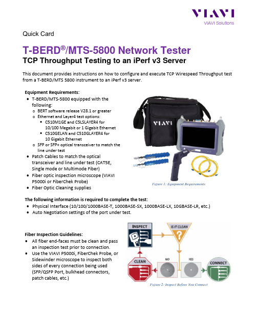
Quick CardT-BERD®/MTS-5800 Network TesterTCP Throughput Testing to an iPerf v3 ServerThis document provides instructions on how to configure and execute TCP Wirespeed Throughput test from a T-BERD/MTS 5800 instrument to an iPerf v3 server.Equipment Requirements:•T-BERD/MTS-5800 equipped with thefollowing:o BERT software release V28.1 or greatero Ethernet and Layer4 test options:▪C510M1GE and C5LSLAYER4 for10/100 Megabit or 1 Gigabit Ethernet▪C510GELAN and C510GLAYER4 for10 Gigabit Etherneto SFP or SFP+ optical transceiver to match theline under test•Patch Cables to match the opticaltransceiver and line under test (CAT5E,Single mode or Multimode Fiber)•Fiber optic inspection microscope (VIAVIP5000i or FiberChek Probe)•Fiber Optic Cleaning suppliesFigure 1: Equipment RequirementsThe following information is required to complete the test:•Physical Interface (10/100/1000BASE-T, 1000BASE-SX, 1000BASE-LX, 10GBASE-LR, etc.)•Auto Negotiation settings of the port under test.Fiber Inspection Guidelines:•All fiber end-faces must be clean and pass an inspection test prior to connection. •Use the VIAVI P5000i, FiberChek Probe, or Sidewinder microscope to inspect bothsides of every connection being used(SFP/QSFP Port, bulkhead connectors,patch cables, etc.)Figure 2: Inspect Before You ConnectConnect to Fiber Under Test (FUT):1.For copper 10/100/1000BASE-T interfacetesting with the T-BERD/MTS 5800v2,connect the Port 1 10/100/1000 RJ-45 jack to the port under test using CAT 5E orbetter cable.2.For copper 10/100/1000BASE-T interfacetesting with the T-BERD/MTS 5800-100G,insert a copper SFP into the Port 1SFP+/SFP28 slot and connect to the portunder test using CAT 5E or better cable. 3.For optical interfaces:•Insert desired SFP or SFP+ into the Port1 slot on the top of T-BERD.•Inspect and, if necessary, clean all SFPs, fibers, and bulkheads, as described onpage 1.•Connect the SFP, QSFP, or CFP4 tothe port under test using a SingleMode or Multimode jumper cablecompatible with the interfaceunder test.Launch and Configure Test:1.Press the Power button to turn on thetest set and view the startup screen.ing the Select Test menu, Quick Launchmenu, or Job Manager, launch anEthernet, Layer 4 TCP Wirespeed, IPv4,Terminate test on port 1 for the desirephysical interface. For example:Ethernet►10/100/1000►Layer 4 TCPWIrespeed►IPv4►P1 Terminate.3.If the test is not in the default settings, tapthe Tools icon , and select. Press to continue and wait for test to reconfigure.4.Press the Setup Soft Key, to displaythe Interface settings tab. If you aretesting a 10/100/1000 Electrical or 1GigEOptical tests with auto negotiationdisabled, select the Physical Layer tab, and configure settings to match the Ethernetport under test.Figure 3: T-BERD 5800v2Figure 4: T-BERD 5800-100GFigure 5: Select TestFigure 6: Layer 4 TCP Wirespeed Test Figure 7: Auto Negotiation Settings5.Navigate to All Streams settings.6.Configure appropriate Source IP, SubnetMask and Default Gateway parameters forthe TBERD 5800 test port, leave all otherparameters at defaults.Figure 8: All Stream settings7.Navigate to TCP Host settings.8.If the circuit under test uses VLAN tagging,select Ethernet tab, set the Encapsulationparameter to VLAN, and configure theappropriate VLAN ID and Priority values.Figure 9: TCP Host, Ethernet Settings9.Select TCP Host Settings tab.10.Set the iPerf Version parameter to 3.11.Set the Direction parameter to Upstreamto test in the TBERD 5800 to iPerf serverdirection or to Downstream to test in theiPerf server to TBERD 5800 direction.12.Set the Connect to Server parameter tothe IP address of the iPerf server.13.Set the Connect to Port parameter to TCPport the iPerf server is listening on.14.Set the Window Size parameter to4194304 bytes.15.If required adjust the Max Seg Sizeparameter to match the circuit under testconfiguration, otherwise leave at default.16.If required configure the TOS or DSCPvalues to match the circuit under testconfiguration, otherwise leave at defaults.17.Set the Transmit Mode parameter to Timeand set the Time parameter to desired test duration in seconds.18.Set the Number of Connections parameterto desired value.19.The T-BERD 5800 is configured for the test. Figure 10: TCP Host SettingsContact Us +1 844 GO VIAVI(+1 844 468 4284)To reach the VIAVI office nearest you,visit /contacts.© 2020 VIAVI Solutions Inc.Product specifications and descriptions in thisdocument are subject to change without notice.1.Press the Results Soft Key, , to view theResults screen.2.If using optical test port, select the Lasertab in the Action panel at the bottom ofthe screen, and press . The buttonwill turn yellow and be relabeled .3.Ensure the TBERD 5800 test portestablished a link to circuit under test asindicated by green Signal Present (optical test port only), Sync Acquired and LinkActive LEDs.4.Set the real-time test results view to TCPHost -> Detailed L4 Stats.5.To start the TCP Throughput test tap onthe Start TCP Client button on the Actions tab at the bottom of the screen andobserve the real-time test results.6.Once the test is finished tap on theReports button in the bottom left screencorner and select Create Report option to generate and save the test report.Figure 11: Check LEDsFigure 12: Start TCP Client Figure 13: Create Report。
基于视频技术的直接交通事件检测
基于视频技术的直接交通事件检测高速公路和城市快速路是承担我国公路运输和城市道路运输的主要道路,具有车速快、流量大等许多特点,一旦发生突发交通事件,极易引发交通事故,严重影响道路的通行能力和运营效率。
在日常的交通运行和交通管理中,如果仅仅依靠人工报告,电视监视等非自动检测方法发现交通事件,不但浪费大量的资源,而且不全面及时,给交通安全带来了隐患。
因此,交通事件自动检测技术越发成为智能交通的研究热点,旨在第一时间快速发现交通事件的地点,利于及时处理交通事件。
交通事件指偶发性交通事故、车辆抛锚、恶劣天气、货物散落、道路养护、体育赛事、规模集会等交通情况。
高速公路和城市快速路上发生的停车、逆行、慢行、拥堵、行人穿越、交通事故是需要重点管控的交通事件。
当发现这些交通事件时,交通事件自动检测系统能够立刻报警,自动记录违章违法依据,同时快速处置交通事件,消除安全隐患、减少交通事件的损失。
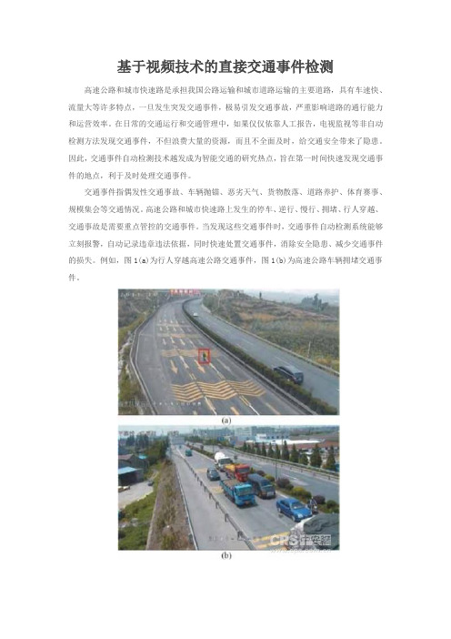
例如,图1(a)为行人穿越高速公路交通事件,图1(b)为高速公路车辆拥堵交通事件。
交通事件的视频检测技术研究概述交通事件自动检测方法图2为交通事件检测研究方法结构示意图,分为自动和非自动检测方法,其中非自动技术主要包括人工报告,电视监视等,自动技术主要有直接和间接检测法。
直接检测法是一种基于视频的处理方法,通过交通事件视频检测算法,直接检测交通事件。
间接检测法是一种基于交通流参数的处理方法,通过模式识别、数学统计、交通模型、人工智能等方法,融合交通流数据检测交通事件。
直接法和间接法的特点可总结如下:1、由于交通系统具有很强的非线性、模糊性、不确定性,研究表明间接法有许多不足之处,不但安装麻烦,而且费用较高,在交通流密度高时,间接法具有较好的检测效果,在交通密度低时检测效果不好。
2、由于直接法是根据视频图像内容,直接判断是否有交通事件发生,研究表明直接法的判别速度上远远胜于间接法,即使交通流量很低,也能对交通事件进行良好的判断。
桥梁交通安全事件的智能分析及预警系统

桥梁交通安全事件的智能分析及预警系统纪玉臣;何军平;姜永栎;虞永方【摘要】In view of the harsh climate of Hangzhou Bay, the full implications of bad weather on the deck intel- ligent monitoring system for Hangzhou Bay Bridge are introduced, based on which a set of solutions are proposed to better monitor incidents by the monitoring system running on the deck of the Hangzhou Bay, and offer timely and ef- fective solutions to the traffic incident occurred on the bridge deck.%针对杭州湾跨海大桥气候恶劣的特点,以及恶劣天气对桥面智能监控系统带来的种种影响问题,进行了系统的介绍。
并且在此基础上提出了一套解决方案,可通过运行在杭州湾桥面上的监控系统,很好地检测出事件,并及时有效地解决桥面上发生的交通事件,减少事故给交通带来的影响。
【期刊名称】《电子科技》【年(卷),期】2012(025)012【总页数】4页(P113-115,129)【关键词】恶劣天气;智能监控;交通事件检测;特大型桥梁【作者】纪玉臣;何军平;姜永栎;虞永方【作者单位】宁波市杭州湾大桥发展有限公司技术养护部,浙江宁波315327;杭州湾跨海大桥管理局技术与养护管理处,浙江宁波315033;宁波海视智能系统有限公司研发部,浙江宁波315040;宁波海视智能系统有限公司研发部,浙江宁波315040【正文语种】中文【中图分类】TP277杭州湾跨海大桥作为特大型桥梁,因其处于海面上的地理位置关系,使得其天气条件变化较多,而且表现不规律。
比利时Traficon Collect-R视频数据检测器

1Traficon 视频检测产品分类1. Collect-R1.1 Collect-R简介Collect-R是基于应用于世界各地的实际案例证明成熟可靠的视频检测技术,属于Traificon产品序列。
Traficon是世界公认的交通视频检测领域的市场领航者。
TrafiCam collector-R是应用在高速公路和城市道路中,集交通数据采集,交通流监控,模拟或者仿真高速公路、城市交通路面中的真实线圈为一体的集成检测器。
可用于短期或者长期的路面应用,TrafiCam Collector-R 是CMOS 摄像头和检测算法为一体的集成检测器。
Collect-R视频检测器1.2 Collect-R主要功能Collect-R视频检测器应用图示1、排队检测监控路面上五种不同级别的拥堵状况,并根据车道占有率及车流速度将其分为五类:普通状态,密集状态,迟缓状态,拥堵状态和停停走走状态。
Traficam collector-R同时可通过物理接口或者RS485连接输出服务等级状态报警。
2、线圈替代功能Traficam collector-R设计为替代地感线圈:代替已存在线圈:线圈仿真4路输出可仿真两组双线圈或者四组单线圈输出与地感线圈输出完全相同。
可替代地感线圈,直接与LDB连接。
其他设置:线圈模拟4路输出可以模仿两组双线圈或者四组单线圈输出信号仅开/关两种3、基本交通数据采集基本交通数据包括:车流量计数测量速度定义车道占有率检测精度等级车型分类(根据车辆长度)五种服务等级(正常、密集、缓慢、拥堵、走走停停) 集成数据1.3 Collect-R 应用Traficam Collector Traficam Collector--R 作为独立系统应用作为独立系统应用Traficam Collector-R 的四路输出可以直接连接VMS 先是大屏的控制器,当有拥堵状况出现的时候,控制器及时给出信息,并在VMS 大屏中显示,通知此路段上的车辆。
Model 801 Series 视频测试生成器快速使用指南说明书

Connecting a Display to the GeneratorNormal Front Panel OperationRestoring Default OperationSetting Digital Video ModeDetailed Status ModeSpecial Serial Port ModesEnabling On- Screen EditingChanging GPIB AddressCloning GeneratorsSelf CalibrationFormat, Image & Sequence Knob List EditorsFormat EditorCustom Image EditorSequenceEditorSequence Mode Front Panel Operation Saving Files Using a New Name801FD, 801GDand 801LDD-SubThis connector only used on the 801GC and 801GX This connector replaced by DVI digital video connector on the 801FD and 801GD and an LDI digital video connector on the 801LDB= Blue VideoCS= Digital (TTL level) Comp SyncG= Green Video= Signal GroundHS= Digital (TTL level) Horizontal SyncI= Intensity Bit(monchrome, LSB) Ib= Blue Intensity Bit Ig= Green IntensityBitIr= Red Intensity Bit = Monitor DisplayCode InputsR= Red VideoV= Video Bit(monchrome, MSB) VS= Digital (TTL level) Vertical SyncNotes:INSTRUCTIONSlish the desired state.to normal.NOTESIf the original format is not stored with a color-difference (e.g. YCrCb) type, then the RB key combination will only switch between RGB and monochrome.The 8-bits/pixel mode is only allowed in the digital video mode on the 801FD and 801GD.If the image index number displayed has only two digits, then a letter may appear just to the left of the two digits as follows to indicate the current state of the generator:“ “ AVST=2 or 4;PELD=0“C” AVST=2 or 4;PELD=8“m” AVST=1 or 3;PELD=0“M” AVST=1 or 3;PELD=8“y” AVST=5,6,7,or 8;PELD=0“Y” AVST=2 or 4;PELD=8“ “ DVST=1,2,5,6, or 7;PELD=0“d” DVST=10;PELD=0“D” DVST=10;PELD=8“b” DVST=9;PELD=0“B” DVST=9;PELD=8“z” DVST=13,14,15,or 16;PELD=0“Z” DVST=13,14,15,or 16;PELD=8OverviewYou can change how your video generator operates by holding down cer-tain front panel button combinations for several seconds during power up and then releasing the buttons. Some modes only apply during the current operating session while others are maintained when the power is cycled. The only way to reset the maintained settings is to either perform a Default Reset or a Memory Re-initialization on power up.Knob lists determine which formats, images and sequences can be selected with the front panel knobs. Please note that on-screen editing must be enabled in or-der to view and modify these lists. Pressing the Image / Step button while view-ing the list will launch the editor.You can display the contents of any signal format using the "Format" test image. Please note that on-screen editing must be enabled in order to modify the dis-played data. Pressing the Image/Step button while viewing the image will then launch the editor.The standard built-in test images can not be modified. However, you can create your own custom test images. Please note that on-screen editing must be en-abled in order to create or modify a custom image. Pressing the Image/Step but-ton while viewing a custom image will hide the image and launch the editor screen.The Sequence Editor can only be accessed through the sequence knob list edi-tor. On-screen editing must be enabled to use either editor.Model 801 Series Quick Start Guide•11•The generator must be programmed to power-up in the sequence mode. This is done by selecting any sequence mode in the sequence editor. The only way to disable the sequence mode is to deselect the mode with the sequence editor. Enabling the on-screen editors on power-up temporarily overrides sequence mode operation.•12•Model 801 Series Quick Start GuideFormats, Custom Images and Sequences are removed from non-volatile memory using the appropriate knob list editor. Pressing the Remove but-ton in the editor displays the following confirmation sub-screen:Model 801 Series Quick Start Guide•13••14•Model 801 Series Quick Start GuideVideo Generator Manager (VGM)The VGM software package provides a graphical user interface that allows you to operate and program our stand alone, ISA card and PCI card Model 801 Series video generators. The current versions of the software run on computers using Microsoft® Windows® 95/98/NT. The software also allows you to save copies of custom formats, images and sequences on the computer's disk drive. These files can then be uploaded into other Model 801 generators. The included custom image editor provides a simple WYSIWYG interface that allows you to quickly setup custom test images.The VGM package includes an extensive "Help" section that covers its op-eration as well as documentation of the commands and queries supported by the generators.A copy of the VGM software is included with each unit sold. The software is also available as free download from the Tech Support area of our Web site at .Smart Testing And Repair (STAR) PackageThe STAR software package allows you set up and document test proce-dures for both DDC and non-DDC compliant monitors. The software runs on computers using MS-Windows 95/98/NT. Please contact your Quantum Data sales representative for more information.Archiver UtilityThe Archiver utility provides a simple text based interface that allows you to communicate with our stand alone, ISA card and PCI card Model 801Series video generators. The software runs as an MS-DOS application. It includes a simple terminal function for sending commands and queries to the generator.The Archiver utility is also used to update the firmware on more recent vin-tage Model 801 Series generators that have the proper Flash EPROMs in-stalled. The software allows you to backup any user created data to disk prior to performing the update. The backed up files can then be updated and uploaded back to the generator after the firmware update.The Archiver software is available as free download from the Tech Support area of our Web site at .Model 801 Series Quick Start Guide •15•Apple Mac MAC_12c Apple Mac MAC_12ce Apple Mac MAC_12m Apple Mac MAC_13c Apple Mac MAC_13LC Apple Mac MAC_13m Apple Mac MAC_15Apple Mac MAC_16Apple Mac MAC_19Apple Mac MAC_1960Apple Mac MAC_21Apple Mac MAC_TVos Apple Mac MAC_TVus ATT PC AT&T_EVC ATT PC AT&T_IVC ATT PC AT&T_SVC Barco BAR2060Barco BAR2080BarcoBAR2560Factory Test TEST150Factory Test TEST250HDTV ATV1259HDTV ATV1259C HDTV ATV1260HDTV ATV1260C HDTV ATV1823HDTV ATV1823P HDTV ATV1824HDTV ATV1824P HDTV ATV1825HDTV ATV1825A HDTV ATV1825P HDTV ATV1829HDTV ATV1829P HDTV ATV1830HDTV ATV1830P HDTV ATV1850HDTV ATV1850A HDTV ATV1859HDTV ATV1860HDTV ATV1923HDTV ATV1923P HDTV ATV1924HDTV ATV1924P HDTV ATV1925HDTV ATV1925A HDTV ATV1925P HDTV ATV1929HDTV ATV1929P HDTV ATV1930HDTV ATV1930P HDTV ATV1950HDTV ATV1950A HDTVATV1959HDTV ATV1960HDTV ATV6429HDTV ATV6429C HDTV ATV6459HDTV ATV6459C HDTV ATV7025HDTV ATV7025E HDTV ATV7025L HDTV ATV7029HDTV ATV7029E HDTV ATV7029L HDTV ATV7050HDTV ATV7050E HDTV ATV7050L HDTV ATV7059HDTV ATV7059E HDTV ATV7059L HDTV ATV7225HDTV ATV7225E HDTV ATV7225L HDTV ATV7229HDTV ATV7229E HDTV ATV7229L HDTV ATV7250HDTV ATV7250E HDTV ATV7250L HDTV ATV7259HDTV ATV7259E HDTV ATV7259L HDTV ATV7625HDTV ATV7650HDTV ATV9325HDTV ATV9329HDTV ATV9350HDTV ATV9359HDTV ATV9625HDTV ATV9629HDTV ATV9650HDTV ATV9659HDTV HDTV_1E HDTV HDTV_1J HDTV HDTV_4E HDTV HDTV_4J HDTV JTV1829HDTV JTV1830HDTV JTV1929HDTV JTV1930H-P HP1060H-P HP1070H-P HP1075A H-P HP1075B H-P HP1260H-P HP1272H-PHP1275IBM Workstation IBM6Km1IBM Workstation IBM6Km2IBM Workstation IBM6Km3IBM Workstation IBM6Km4Intecolor INT1160Intecolor INT1176Intecolor INT1660Intecolor INT1676Lockheed LMC_1Lockheed LMC_2Lockheed LMC_3Lockheed LMC_4Military HOBO Military MAVERIK NEC PC NECPC400NEC PC NECPC750NTSC NoBurst RS170Y NTSC NoBurst RS170Yos NTSC NoBurst RS170Yus NTSC w/Burst NTSC_443NTSC w/Burst NTSC_601NTSC w/Burst NTSC4xSC NTSC w/Burst NTSCTVos NTSC w/Burst NTSCTVus PAL NoBurst PAL_Y PAL NoBurst PAL_Yos PAL NoBurst PAL_Yus PAL w/Burst PAL_4xSC PAL w/Burst PAL_N PAL w/Burst PAL_TVos PAL w/Burst PAL_TVus PAL w/Burst PALTV601PC CGA_m14PC EGA_m2PC HGC_text PC HGCgraph PC IBM_3164PC IBM_3179PC MDA_m7PC PGA_400PC PGA_480PC VGA_m1PC VGA_m2PC VGA_m3PC VGA_m4PC XGA_m4a PC XGA_m4b PC XGA_m5PC XGA_m6PC XGA1076PC XGA2PC XGA6475Sony SON1072Sony SON1274SonySON1276STANAG STANAGA STANAG STANAGB STANAG STANAGC Sun Micro SUN1061Sun Micro SUN1077Sun Micro SUN1166Sun Micro SUN116B Sun Micro SUN1176Sun Micro SUN117B Sun Micro SUN1267Sun Micro SUN126B Sun Micro SUN1276Sun Micro SUN1667VESA DMT1075VESA DMT1085VESA DMT1170VESA DMT1175VESA DMT1185VESA DMT1243VESA DMT1260VESA DMT126A VESA DMT1275VESA DMT127A VESA DMT1285VESA DMT128A VESA DMT1648VESA DMT1660VESA DMT1665VESA DMT1670VESA DMT1675VESA DMT1680VESA DMT1685VESA DMT1760VESA DMT1775VESA DMT1860VESA DMT1875VESA DMT1960VESA DMT1975VESA DMT6475VESA DMT6485VESA DMT648A VESA DMT648B VESA DMT7285VESA DMT8075VESA DMT8085VESA VG900601VESA VG900602VESA VG901101VESA VS900603VESA VS901101VESA VS910801ViewSonic VPD180_8ViewSonicVPD180_4TypeNameTypeNameTypeNameTypeNameQuantum Data, Inc.2111 Big Timber Rd Elgin, IL 60123-1100U.S.A.®。
比利时Traficon VIP-T视频事件检测器
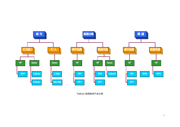
Traficon 视频检测产品分类11. VIP-T1.1 VIP-T简介VIP-T是基于应用于世界各地的实际案例证明成熟可靠的视频检测技术,属于Traificon产品序列。
Traficon自1979年开始专业研发视频事件检测器,目前已经成为视频检测的世界级参照。
Traficon视频检测系统专门为道路交通控制提供实时的交通数据及图像信息、交通异常事件的快速准确检测。
Traficon视频检测系统的核心是VIP(视频图像处理单元 Video Image Processor),VIP模块根据视频图像进行处理,同时完成交通监控、异常交通事件检测和交通数据采集等功能。
用于监控功能的摄像机视频信号经视频分配后可作为Traficon视频事件检测VIP模块的输入,经各种检测算法在VIP模块内的多任务并行处理运算,输出一系列的交通数据(车流量、平均车速、车道占有率...)以及异常交通事件信息。
VIP-T交通视频事件检测器视频事件检测系统为交通控制管理提供实时交通参数及事件信息1.2 VIP-T主要功能VIP-T 适用于集中式及分布式监控系统中。
VIP-T将交通事件(隧道内或外场)自动检测报警,交通参数采集,车辆存在检测功能集成于一体,并结合实时交通视频流压缩编码,通过IP网络传输,构成完美的交通视频检测系统。
开放的系统架构和模块化系统设置提供给用户一个可扩展增容的系统。
VIP-T采用标准摄像机采集的视频作为输入进行检测。
各种图像处理算法并行运算,为实现多种检测功能进行多任务并行处理。
VIP-T 允许用户根据项目应用需要及摄像机安装位置选择相应所需的检测功能。
视频检测功能与MPEG-4视频信号压缩功能可独立运行,使得系统具有可扩展性并易于升级。
下图为VIP-T进行交通事件检测及交通数据采集的画面隧道内停车逆行交通数据采集下表列出VIP-T 系统交通数据采集及事件检测的内容自动事件检测交通事件非交通事件停车隧道内烟雾逆行行人速度突然下降遗撒物交通拥堵道路服务等级技术报警低速行驶视频质量低下超速行驶摄像机位置移动遥控摄像机画面变动车辆存在交通参数采集每车道交通流数据交通流平均车速车道占有率集成的车辆交通参数车流量(计数) 和平均车速/车型/车道,车头间距,平均间隔时间/车型长度/车道,占有率,密度和车型长度/车道单个车辆的交通参数采用MPEG-4 视频压缩技术,VIP-T 提供在网络环境中显示及点播实时视频流功能。
- 1、下载文档前请自行甄别文档内容的完整性,平台不提供额外的编辑、内容补充、找答案等附加服务。
- 2、"仅部分预览"的文档,不可在线预览部分如存在完整性等问题,可反馈申请退款(可完整预览的文档不适用该条件!)。
- 3、如文档侵犯您的权益,请联系客服反馈,我们会尽快为您处理(人工客服工作时间:9:00-18:30)。
Traficon 视频检测产品分类11. VIP-T1.1 VIP-T简介VIP-T是基于应用于世界各地的实际案例证明成熟可靠的视频检测技术,属于Traificon产品序列。
Traficon自1979年开始专业研发视频事件检测器,目前已经成为视频检测的世界级参照。
Traficon视频检测系统专门为道路交通控制提供实时的交通数据及图像信息、交通异常事件的快速准确检测。
Traficon视频检测系统的核心是VIP(视频图像处理单元 Video Image Processor),VIP模块根据视频图像进行处理,同时完成交通监控、异常交通事件检测和交通数据采集等功能。
用于监控功能的摄像机视频信号经视频分配后可作为Traficon视频事件检测VIP模块的输入,经各种检测算法在VIP模块内的多任务并行处理运算,输出一系列的交通数据(车流量、平均车速、车道占有率...)以及异常交通事件信息。
VIP-T交通视频事件检测器视频事件检测系统为交通控制管理提供实时交通参数及事件信息1.2 VIP-T主要功能VIP-T 适用于集中式及分布式监控系统中。
VIP-T将交通事件(隧道内或外场)自动检测报警,交通参数采集,车辆存在检测功能集成于一体,并结合实时交通视频流压缩编码,通过IP网络传输,构成完美的交通视频检测系统。
开放的系统架构和模块化系统设置提供给用户一个可扩展增容的系统。
VIP-T采用标准摄像机采集的视频作为输入进行检测。
各种图像处理算法并行运算,为实现多种检测功能进行多任务并行处理。
VIP-T 允许用户根据项目应用需要及摄像机安装位置选择相应所需的检测功能。
视频检测功能与MPEG-4视频信号压缩功能可独立运行,使得系统具有可扩展性并易于升级。
下图为VIP-T进行交通事件检测及交通数据采集的画面隧道内停车逆行交通数据采集下表列出VIP-T 系统交通数据采集及事件检测的内容自动事件检测交通事件非交通事件停车隧道内烟雾逆行行人速度突然下降遗撒物交通拥堵道路服务等级技术报警低速行驶视频质量低下超速行驶摄像机位置移动遥控摄像机画面变动车辆存在交通参数采集每车道交通流数据交通流平均车速车道占有率集成的车辆交通参数车流量(计数) 和平均车速/车型/车道,车头间距,平均间隔时间/车型长度/车道,占有率,密度和车型长度/车道单个车辆的交通参数采用MPEG-4 视频压缩技术,VIP-T 提供在网络环境中显示及点播实时视频流功能。
VIP-T 遵循实时流控协议 (RTSP) ,提供全帧率的实时视频码流。
VIP-T采用MPEG-4 压缩功能自动记录交通事件发生前后一段时间的视频序列。
当VIP-T 检测到交通事件,系统自动启动视频序列的存储记录进程。
洒落物行人VIP-T 检测产生的所有交通数据,事件,报警和视频图像都通过网络传送给上端的Traficon®管理系统,TMS 。
视频事件管理服务器将交通数据,事件,报警信息存储于关系型数据库中。
实时的交通信息则通过TCP/IP socket (套接字)取得。
T-Port软件负责管理视频事件检测器检测的所有结果。
T-port管理软服务器安装在监控中心任意一台计算机上,同时在其他的计算机 (同一网段内) 上可安装相应的客户端界面,从不同的地区查询服务器上的事件检测器状况,也可同时查询多台服务器上的事件检测器信息,提高的管理人员的工作效率。
T-Port有两种运行模式:维护模式或者监控和报告模式。
T-port采用中文界面。
T-Port服务器软件运行在安装 Windows 2000 或者 Windows XP的视频事件管理计算机上,通过网络IP自动检索所有的视频事件检测器。
图示为T-port界面的左上角是系统硬件树。
界面右侧显示报警和事件的时间、类型、摄像机位置、录像。
T-port界面只要点击界面上的任何一个视频事件检测器,用户就可以看到外场的实时图像和视频流。
视频序列文件上面图例的左下是一个停车事件的图像,表明有事件发生。
相应的事件录像文件会出现在界面的右侧。
点击右侧的事件集,事件录像文件将自动展开。
管理员可以点击相应的事件,事件将自动回放。
维护模式T-Port处于维护模式时,维护人员可以更改系统设置或配置,这不会影响到系统的正常工作。
通过T-Port ,用户可以远程设置视频检测系统。
例如,维护员可以远程设置每个视频事件检测器、检测区、初始值、时间参数等。
此外T-Port 服务器✧接受数据、报警和图像序列/录像✧将数据和报警保存在可以访问的MySQL的数据库中(存储在硬盘上)✧将图像序列/录像保存到电脑硬盘上✧控制整个安装的正常工作✧产生交通数据报告✧与其它设备通讯:矩阵或通过以太网与其它电脑管理员、操作员和一般用户都可以进入T-Port 软件。
T-port 软件运行在Windows环境下,输入密码便可以进入。
可以为不同用户设置不同的使用权限。
T-port有一个 MySQL 关系数据库。
这个数据库可以保存数据、报警和图像序列(备选)。
在设置时,用户可以定义数据库的容量和寿命。
系统管理员可以制作ZIP或CD-ROM备份。
屏蔽功能屏蔽功能可过滤掉控制人员不想看到的报警,比如说隧道内会在一定时间内进行维护,此时视频事件检测器会对维护车辆或人员做“停车”“行人”等报警,管理人员可以对T-port软件做一些相应设置,无意义的报警将会自动过滤掉。
比如在设置时用户可以设置在某种交通状况下“屏蔽”某些报警。
例如,在交通拥堵时不做任何停车报警。
这将有效减少误报。
T-port还有高级过滤器, 多种过滤功能同时应用,保证管理人员有效的管理隧道或者高速公路,减轻管理人员的负担。
综合的图形用户界面(GUI)此软件非常用户友好:下拉菜单、图形和多语种支持。
通过Traficon开放的标准软件开发协议SDK,可以很容易开发与其它设备联动的系统。
与监控软件的界面T-Port 软件可以集成到上层交通管理系统。
可以利用Traficon提供的软件开发包(SDK)为上层的监控系统提取视频检测系统提供的数据和报警。
交通数据、事件报告模式交通数据统计报告可以以表格形式呈现并输出到EXCEL。
也可以以图形呈现,如下图所示。
交通数据报告模式实时视频查看可以通过网络查看每个视频事件检测器的实时动态视频。
某摄像机实时视频显示1.3 VIP-T应用典型的视频事件检测系统包括:前端用于视频监控的摄像机、视频信号传输系统(光纤、光端机)、视频分配器、视频事件检测分析仪(VIP模块)、网络交换机、视频事件检测服务器及客户机。
Traficon视频检测系统说明:✧系统主要由两部分组成:前端视频采集摄像机(隧道内定焦)和监控站中心的视频事件检测器及管理计算机(配置相应管理软件)。
✧摄像机安装于隧道内侧壁处,为保证隧道内视频检测范围全覆盖,间隔100米布设一台摄像机。
通过视频光端机将视频信号传到隧道监控站,通过视频分配器分配视频接入到视频事件检测器VIP-T。
✧Traficon VIP-T系统安装于监控中心,所有交通事件和交通参数的检测都在机架中的VIP-T模块上完成,每个机架可以同时处理8路视频图像。
✧机架中的VIP-T通过以太网TCP/IP把数据和报警录像(MPEG-4压缩)上传到视频事件管理计算机上。
✧安装在视频事件管理计算机上的T-port管理软件统一管理所有数据和报警事件。
管理系统TMS 服务器端` TMS 客户端MPEG-4 解压缩及视频监视模拟视频监视器VIP-T VIP-TVIP-TVIP-T视频事件检测系统VIP-T视频事件检测系统广泛应用在高速公路、隧道、公路大桥及城市快速路作为交通数据采集及事件检测。
高速公路隧道公路大桥城市快速路VIP-T典型交通管理系统界面1.4 VIP-T 安装及接线VIP-T 机柜安装示意图AC 220V 50HzSONY SONYSONY SONY SONY SONYVIP-T 系统接线图1.5 视频采集摄像机选用及安装建议1、摄像机杆体应保持稳定,最大晃动不能超过Max deflection = tg 1° x H (H--杆高度)2、调整摄像机安装角度,避免检测画面中出现地平线3、选择推荐的摄像机(咨询厂家),适合作为视频事件检测之用。
并调整摄像参数避免视频采集画面出现光晕及拖尾现象。
光晕拖尾3、调整摄像机安装高度及角度,避免检测画面中出现前后、左右遮挡4、调整摄像机画面尽量位于检测车道的垂直正上方位置1.6 VIP-T性能参数检测内容 高速公路/快速路 隧道 检测时间流 量 >98% >95%占有率 >95% >95%速 度 >95% >95%车头距 >95% >95%停车、撞车 >95% >98% ≤10秒钟拥堵/排队 >98% >98% 5秒钟 逆 行 >95% >98% 5秒钟遗撒物 >95% >98% ≤10秒钟超速行驶 >98% >98% 5秒钟突然减速 >98% >98% ≤10秒钟*** Traficon检测系统是基于清晰的视频输入的交通检测解决方案,所以在摄像机安装位置理想的情况下,系统可达到以上性能参数。
