红外遥控系统中英文对照外文翻译文献
红外传感器论文中英文资料对照外文翻译
中英文资料对照外文翻译外文资料Moving Object Counting with an Infrared Sensor NetworkBy KI, Chi KeungAbstractWireless Sensor Network (WSN) has become a hot research topic recently. Great benefit can be gained through the deployment of the WSN over a wide range of applications, covering the domains of commercial, military as well as residential. In this project, we design a counting system which tracks people who pass through a detecting zone as well as the corresponding moving directions. Such a system can be deployed in traffic control, resource management, and human flow control. Our design is based on our self-made cost-effective Infrared Sensing Module board which co-operates with a WSN. The design of our system includes Infrared Sensing Module design, sensor clustering, node communication, system architecture and deployment. We conduct a series of experiments to evaluate the system performance which demonstrates the efficiency of our Moving Object Counting system.Keywords:Infrared radiation,Wireless Sensor Node1.1 Introduction to InfraredInfrared radiation is a part of the electromagnetic radiation with a wavelength lying between visible light and radio waves. Infrared have be widely used nowadays including data communications, night vision, object tracking and so on. People commonly use infrared in data communication, since it is easily generated and only suffers little from electromagnetic interference. Take the TV remote control as an example, which can be found in everyone's home. The infrared remote control systems use infrared light-emitting diodes (LEDs) to send out an IR (infrared) signal when the button is pushed. A different pattern of pulses indicates the corresponding button being pushed. To allow the control of multiple appliances such as a TV, VCR, and cable box, without interference, systems generally have a preamble and an address to synchronize the receiver and identify the source and location of the infrared signal. To encode the data, systems generally vary the width of the pulses (pulse-width modulation) or the width of the spaces between the pulses (pulse space modulation). Another popular system, bi-phase encoding, uses signal transitions to convey information. Each pulse is actually a burst of IR at the carrier frequency. A 'high' means a burst of IR energy at the carrier frequency and a 'low' represents an absence of IR energy. There is no encoding standard. However, while a great many home entertainment devices use their own proprietary encoding schemes, somequasi-standards do exist. These include RC-5, RC-6, and REC-80. In addition, many manufacturers, such as NEC, have also established their own standards.Wireless Sensor Network (WSN) has become a hot research topic recently. Great benefit can be gained through the deployment of the WSN over a wide range of applications, covering the domains of commercial, military as well as residential. In this project, we design a counting system which tracks people who pass through a detecting zone as well as the corresponding moving directions. Such a system can be deployed in traffic control, resource management, and human flow control. Our design is based on our self-made cost-effective Infrared Sensing Module board which co-operates with a WSN. The design of our system includes Infrared Sensing Module design, sensor clustering, node communication, system architecture and deployment. We conduct a series of experiments to evaluate the system performance which demonstrates the efficiency of our Moving Object Counting system.1.2 Wireless sensor networkWireless sensor network (WSN) is a wireless network which consists of a vast number of autonomous sensor nodes using sensors to monitor physical or environmental conditions, such as temperature, acoustics, vibration, pressure, motion or pollutants, at different locations. Each node in a sensor network is typically equipped with a wireless communications device, a small microcontroller, one or more sensors, and an energy source, usually a battery. The size of a single sensor node can be as large as a shoebox and can be as small as the size of a grain of dust, depending on different applications. The cost of sensor nodes is similarly variable, ranging from hundreds of dollars to a few cents, depending on the size of the sensor network and the complexity requirement of the individual sensor nodes. The size and cost are constrained by sensor nodes, therefore, have result in corresponding limitations on available inputs such as energy, memory, computational speed and bandwidth. The development of wireless sensor networks (WSN) was originally motivated by military applications such as battlefield surveillance. Due to the advancement in micro-electronic mechanical system technology (MEMS), embedded microprocessors, and wireless networking, the WSN can be benefited in many civilian application areas, including habitat monitoring, healthcare applications, and home automation.1.3 Types of Wireless Sensor NetworksWireless sensor network nodes are typically less complex than general-purpose operating systems both because of the special requirements of sensor network applications and the resource constraints in sensor network hardware platforms. The operating system does not need to include support for user interfaces. Furthermore, the resource constraints in terms of memory and memory mapping hardware support make mechanisms such as virtual memory either unnecessary or impossible to implement. TinyOS [TinyOS] is possibly the first operating system specifically designed for wireless sensor networks. Unlike most other operating systems, TinyOS is based on an event-driven programming model instead of multithreading. TinyOS programs are composed into event handlers and tasks with run to completion-semantics. When an external event occurs, such as an incomingdata packet or a sensor reading, TinyOS calls the appropriate event handler to handle the event. The TinyOS system and programs are both written in a special programming language called nesC [nesC] which is an extension to the C programming language. NesC is designed to detect race conditions between tasks and event handlers. There are also operating systems that allow programming in C. Examples of such operating systems include Contiki [Contiki], and MANTIS. Contiki is designed to support loading modules over the network and supports run-time loading of standard ELF files. The Contiki kernel is event-driven, like TinyOS, but the system supports multithreading on a per-application basis. Unlike the event-driven Contiki kernel, the MANTIS kernel is based on preemptive multithreading. With preemptive multithreading, applications do not need to explicitly yield the microprocessor to other processes.1.4 Introduction to Wireless Sensor NodeA sensor node, also known as a mote, is a node in a wireless sensor network that is capable of performing processing, gathering sensory information and communicating with other connected nodes in the network. Sensor node should be in small size, consuming extremely low energy, autonomous and operate unattended, and adaptive to the environment. As wireless sensor nodes are micro-electronic sensor device, they can only be equipped with a limited power source. The main components of a sensor node include sensors, microcontroller, transceiver, and power source. Sensors are hardware devices that can produce measurable response to a change in a physical condition such as light density and sound density. The continuous analog signal collected by the sensors is digitized by Analog-to-Digital converter. The digitized signal is then passed to controllers for further processing. Most of the theoretical work on WSNs considers Passive and Omni directional sensors. Passive and Omni directional sensors sense the data without actually manipulating the environmen t with active probing, while no notion of “direction” involved in these measurements. Commonly people deploy sensor for detecting heat (e.g. thermal sensor), light (e.g. infrared sensor), ultra sound (e.g. ultrasonic sensor), or electromagnetism (e.g. magnetic sensor). In practice, a sensor node can equip with more than one sensor. Microcontroller performs tasks, processes data and controls the operations of other components in the sensor node. The sensor node is responsible for the signal processing upon the detection of the physical events as needed or on demand. It handles the interruption from the transceiver. In addition, it deals with the internal behavior, such as application-specific computation.The function of both transmitter and receiver are combined into a single device know as transceivers that are used in sensor nodes. Transceivers allow a sensor node to exchange information between the neighboring sensors and the sink node (a central receiver). The operational states of a transceiver are Transmit, Receive, Idle and Sleep. Power is stored either in the batteries or the capacitors. Batteries are the main source of power supply for the sensor nodes. Two types of batteries used are chargeable and non-rechargeable. They are also classified according to electrochemical material used for electrode such as NiCd(nickel-cadmium), NiZn(nickel-zinc), Nimh(nickel metal hydride), and Lithium-Ion. Current sensors are developed which are able to renewtheir energy from solar to vibration energy. Two major power saving policies used are Dynamic Power Management (DPM) and Dynamic V oltage Scaling (DVS). DPM takes care of shutting down parts of sensor node which are not currently used or active. DVS scheme varies the power levels depending on the non-deterministic workload. By varying the voltage along with the frequency, it is possible to obtain quadratic reduction in power consumption.1.5 ChallengesThe major challenges in the design and implementation of the wireless sensor network are mainly the energy limitation, hardware limitation and the area of coverage. Energy is the scarcest resource of WSN nodes, and it determines the lifetime of WSNs. WSNs are meant to be deployed in large numbers in various environments, including remote and hostile regions, with ad-hoc communications as key. For this reason, algorithms and protocols need to be lifetime maximization, robustness and fault tolerance and self-configuration. The challenge in hardware is to produce low cost and tiny sensor nodes. With respect to these objectives, current sensor nodes usually have limited computational capability and memory space. Consequently, the application software and algorithms in WSN should be well-optimized and condensed. In order to maximize the coverage area with a high stability and robustness of each signal node, multi-hop communication with low power consumption is preferred. Furthermore, to deal with the large network size, the designed protocol for a large scale WSN must be distributed.1.6 Research IssuesResearchers are interested in various areas of wireless sensor network, which include the design, implementation, and operation. These include hardware, software and middleware, which means primitives between the software and the hardware. As the WSNs are generally deployed in the resources-constrained environments with battery operated node, the researchers are mainly focus on the issues of energy optimization, coverage areas improvement, errors reduction, sensor network application, data security, sensor node mobility, and data packet routing algorithm among the sensors. In literature, a large group of researchers devoted a great amount of effort in the WSN. They focused in various areas, including physical property, sensor training, security through intelligent node cooperation, medium access, sensor coverage with random and deterministic placement, object locating and tracking, sensor location determination, addressing, energy efficient broadcasting and active scheduling, energy conserved routing, connectivity, data dissemination and gathering, sensor centric quality of routing, topology control and maintenance, etc.中文译文移动目标点数与红外传感器网络作者KI, Chi Keung摘要无线传感器网络(WSN)已成为最近的一个研究热点。
红外发射和接收电路设计外文翻译
外文文献原稿和译文原稿IntroductionInfrared remote control system is mainly composed by the remote control transmitter, integrated receiver head, microcontroller, interface circuit shown in Figure 1. The remote control is used to generate the remote encoder pulse drive infrared emission control output of the infrared remote control signal, the remote control receiver on the remote control signal amplification, detection, shaping, demodulation remote encoder pulse. The remote control encoder pulse is a serial binary code for the infrared remote control system, the serial code input to the microcontroller, its internal CPU instruction decode on the remote control, and perform remote control functions. Using the remote control as the input of the control system, we need to address the following key questions: how to receive the infrared remote control signal; how to identify the infrared remote control signal, and decoding software design, design of control procedures.SCM historySCM was born in 1971, has gone through three major phases of the SCM, the MCU SoC.It consists of computing device, controller, memory, input output devices.Its full name is a single-chip microcomputer, is typical of embedded micro-controller (Microcontroller Unit), the commonly used letters of the abbreviation MCU single-chip, and it was first used in the field of industrial control.Master microcontroller technology to enable more people in the industry, students, enthusiasts, product developers, the question arose due to the extensive application of SCM in the field of industrial control, microcontroller development board, the more famous such as e-DZR-01A microcontroller development board.Microcontroller chip dedicated processor developed from the CPU.The firstdesign concept by a large number of peripherals and CPU integrated in a single chip, the computer system is smaller, more easily integrated into complex and require strict control equipment on the volume.Single-chip, also known as single-chip microcontroller, it is not the completion of a logical function of the chip, but a computer system integrated onto one chip.Equivalent to a mini-computer and computer, microcontroller only the lack of I / O devices.SCM rely on the program is running, and can be modified.Different functions through different programs, especially the special unique function, which is the other devices require much effort to do, while others make great efforts it is difficult to do.A not very complex functions using pure hardware to get the words of the 1950s developed 74 series, or 60 during the CD4000 series, the circuit must be a big PCB board!If successful on the market in the United States in the 1970s series of microcontrollers, the result will be different!Just because a program written by the MCU through you can achieve high intelligence, high efficiency and high reliability!Microcontroller for cost sensitive, so accounting for the dominance of the software or the lowest level assembly language, which is the lowest level than binary machine code language, since such low-level why use it?A lot of high-level language has reached a level of visual programming, why not?The reason is simple, is the microcontroller does not have a home computer as the CPU, also not as hard as mass storage devices.A visual high-level language to write small programs inside even if there is only one button, will reach tens of K of size!Nothing in terms of home PC's hard drive, but for SCM in terms of is not acceptable.SCM in the utilization of hardware resources must be high, so the compilation of the original while still in heavy use.The same reason, if the computer giant's operating system and application software to get home PC run up to the home PC can not afford.It can be said that the twentieth century across the three "power" era of the electrical era, the electronic age and has now entered the computer age.However, such a computer, usually refers to a personal computer, or PC.It is by the host, keyboard, monitor, and so on.Another type of computer, not how most people are familiar with.This computer is smart to give a variety of mechanical microcontroller(also known as micro-controller).The name suggests, the smallest of this computer system using only one IC to make a simple calculation and control.Because of its small, usually hidden in a controlled mechanical "stomach".Throughout the device, it plays like the role of the human mind, it is wrong, the entire device was paralyzed.Now, this single chip field of use has a very wide, such as smart meters, real-time industrial control, communications equipment, navigation systems, home appliances and so on.A variety of products using the SCM, you can play the effect of product upgrades, often preceded by an adjective in front of the product name - "smart", such as smart washing machines.Some factories or other amateur electronics developers to engage in out of certain products, not the circuit is too complicated, too simple and can easily be imitation.The reason may be stuck in the product does not use a microcontroller or other programmable logic devices.Microcontroller applicationsMCU to infiltrate all areas of life, almost difficult to find which areas of the microcontroller trail.Navigation device of the missile, aircraft, various instrument control, computer network communications and data transmission, industrial automation and process real-time control and data processing, widely used smart card IC, civil luxury car security system, VCR,cameras, the control of automatic washing machines, and program-controlled toys, electronic pets, etc., which are inseparable from the microcontroller.Not to mention the field of automatic control, robotics, intelligent instruments, medical equipment.Therefore, the learning, development and application of the SCM will create a number of computer applications and intelligent control of the scientists, engineers.The microcontroller is widely used in the field of instrumentation, home appliances, medical equipment, aerospace, equipment for the intelligent management and process control, generally can be divided into the following categories:1. On smart instrumentationThe microcontroller has a small size, low power consumption, and control functions, and expansion of the advantages of flexibility, miniaturization and easy to use, widely used in instrumentation, combined with different types of sensors can berealized such as voltage, power, frequency, humidity, temperature,flow, speed, thickness, angle, length, hardness, elements, pressure and other physical measurement.SCM makes the digital instrumentation, intelligent, miniaturization and more powerful function than the use of electronic or digital circuits.Such as precision measuring equipment (power meter, oscilloscope, analyzer).2.In industrial control applicationsMCU can constitute various forms of control systems, data acquisition systems.Such as factory assembly line of intelligent pipe3.in Household AppliancesIt can be said of home appliances is basically using the MCU control, electric rice praise, washing machines, refrigerators, air conditioners, color TVs, and other audio video equipment, then the electronic weighing equipment, varied, omnipresent.4.in the field of computer networks and communicationModern microcontroller with universal communication interface can be easily and computer data communications, provides excellent material for use in computer networks and communication devices, communication equipment basically to the MCU intelligent control from themobile phones, telephones, small program-controlled switchboards, building automated communications call systems, train radio communications, and then to the ubiquitous mobile phones in their daily work, trunking mobile communication radios.5.Chip in the field of medical equipmentThe microcontroller uses in medical devices is also quite extensive, such as medical ventilator, a variety of analyzers, monitors, ultrasound diagnostic equipment and hospital beds call system and so on.6.Modular applications in a variety of large appliancesSome dedicated microcontroller designed for specific functions, modular applications in a variety of circuit, without requiring the use of personnel to understand its internal structure.Integrated single-chip, such as music, seemingly simple function, miniature pure electronic chip (as opposed to the principle of the tape drive), you need a complex similar to the principle of the computer.Such as: themusic signal in digital form in memory (similar to the ROM), read by the microcontroller into analog music signal (similar to the sound card).In large circuits, this modular application greatly reduce the size, simplifying the circuit, reducing the damage, error rate, is also convenient to replace.7.Chip in the field of automotive equipmentThe microcontroller is widely used in automotive electronics, such as automotive engine controllers, intelligent electronic controller based on CAN bus automotive engine, GPS navigation system, abs anti-lock systems, braking systems, etc..In addition, the microcontroller business, finance, scientific research, education, defense, aerospace and other fields has a very wide range of applications, microcontroller development prospects are very objective.Speaking in general terms: the MCU's small size, light weight, inexpensive, and provide favorable conditions for learning, application and development.At the same time, learning to use the microcontroller is the best choice for the understanding of computer theory and structure.SCM is the best choice for people to study and application of related technologies.Master chip AT89S51The AT89S51 ATMEL Corporation in the United States low-power, high-performance CMOS8 bit microcontroller, on-chip containing 4k bytes of system programming of flash read-only program memory, the device using ATMEL high density nonvolatile memory technology to produce compatiblestandard 8051 instruction set and pin.It combines the Flash program memory can Programming (ISP) can also be used the traditional method of programming and general-purpose 8-bit microprocessor on a single chip.Features OverviewAT89S51 provides the following standard features: 4k bytes of Flash flash memory, 128 bytes of internal RAM, 32 I / O port lines, Watchdog Timer (WDT), two data pointers, two 16-bit timer / counters, a fivetwo vector interrupt structure, a full duplex serial port, on-chip oscillator and clock circuitry., AT89S51 can bereduced to the 0Hz static logic operation, and supports two software selectable power saving modes.Free way to stop the CPU, but allows the RAM, timer / counters, serial communication port and interrupt system to continue to work.The power down mode to save the contents of RAM, but the oscillator is stopped and prohibited all other parts of the work until the next hardware reset.In view of the subject requirements, the AT89S51 chip to achieve the purpose of more convenient, fast and comprehensive.译文介绍红外遥控系统主要由遥控发射器、一体化接收头、单片机、接口电路组成,如图一所示。
外文翻译-- 基于STC单片机的红外遥控开关系统的设计

JSJ-1302计算机信息工程学院2013 届毕业设计(论文)外文阅读与翻译毕业设计题目基于STC单片机的红外遥控开关系统的设计外文翻译题目Decoding Infraed Remote Controls Using a PIC16C5X Microcontroller专业计算机信息科学与技术班级姓名学号指导教师职称介绍:家用电子工业已经应用红外遥控器控制电视机,录像机和有线电视很多年了。
同样的技术最近开始应用于工业应用以替代小键盘。
可以通过PIC16C5X译解大多数的红外信号。
这份说明书是描述如何破解的。
唯一用来译解IR信号的强制性硬件是红外接收仪。
它的两种类型的用法在这里都有说明。
两种模块类型都经常被用于家用电子工业。
第一种类型响应的已调制的红外信号大概为40KHz。
第二种响应未调制的红外脉冲并且有受限范围。
每种类型的硬件成本都不高于2美元。
此处描述了三种PIC16C5X应用程序,说明了如何用它们来创建一个算法使其能够破译任何遥控信号。
每种PIC16C5X应用程序表示在映射出一个预先存在的红外格式的一个步骤。
最终的应用程序是一个用来完全实现的示例的红外信号解码和解调的一种Teknika电视遥控器。
三个层次的红外线信号典型的红外信号遥控器有三层。
用于这些层的名字没有被标准化。
在这个应用程序中注意他们被称为“红外、调制和串行数据。
红外层是种发射方式。
红外线是一种因为波长太长以至于看不到的光。
虽然你不能看到红外光束,但它是光的一种形式,所以如果你不能看到目标设备,你就不能用红外信号控制它。
控制绕过拐角,通过不透明的材料、RF,通常使用超高频信号。
虽然这个应用程序注没有进一步提到RF,这里介绍的许多东西都是可以用作一个射频传输介质。
这个频率层爆出的红外信号通常是在频率调制32.75千赫和56.8千赫之间。
这样做是为了减少环境光的影响。
虽然考虑到这一层,但还是可选的。
如果不调整红外格式的输出,发送脉冲与未调整的红外线则相反。
红外遥控系统毕业论文中英文资料对照外文翻译文献
中英文资料对照外文翻译文献红外遥控系统摘要目前红外数据通信技术是在世界范围内被广泛应用的一种无线连接技术,它也可以被许多软硬件平台所支持。
红外收发器产品具有成本低,体积小,传输速率快,点对点传输安全性好,不受电磁干扰等特点,可使得信息在几个不同产品器件之间快速、便捷、安全地交换与传输。
红外数据通信技术在短距离无线传输领域内有着十分显著的优势,红外遥控收发系统的设计和存在具有非常高的运用价值。
目前,红外收发器产品在便携式产品中的应用潜力很大。
全世界约有1亿5千万台设备和仪器是采用红外数据通信技术的,在电子产品、工业设备、医疗设备等领域内使用范围很广。
几乎所有笔记本电脑、手机都配置红外收发器接口。
伴随着红外数据传输技术的愈发成熟、生产和使用成本下降,红外收发器在短距离通讯领域内将会得到更加广泛的应用。
设计这个系统的目的是用红外线作为传输媒介来传输操作者或用户的操作信息和指令,然后由接收器电路翻译出原信号,主要是利用编码芯片和解码芯片对信号进行调制解调,这其中,编码芯片用的是台湾生产的PT2262,解码芯片是PT2272。
它们的主要工作原理是:通过编码键盘可以为PT2262提供输入信息,PT2262对输入的信息进行编码并加载到38KHZ 的载波上并调制红外发射二极管,再将其辐射到空间,然后再由接收系统接收信号并解调出原始的信息内容,由PT2272对原信号进行解码,从而驱动相应的电路完成用户的操作指令和操作要求。
关键字:红外线;编码;解码;LM386;红外收发器。
1 绪论1.1 课题研究的背景及意义目前,在世界范围内,红外数据通信技术是被广泛使用的一种无线连接技术,被许多的硬件和软件平台所支持。
是一种通过数据脉冲与红外脉冲之间的相互转换实现无线数据收发的技术。
红外收发器产品具有成本低,体积小,传输速率快,点对点传输安全性好,不受电磁干扰等特点,可使得信息在几个不同产品器件之间快速、便捷、安全地交换与传输。
单片机红外遥控外文翻译
Infrared Remote And Chips Are IntroducedPeople's eyes can see the visible wavele ngth from long to short accord ing to the arrangement, in order to red, orange, yellow, green, green, blue, violet. One of the red wavelengths for 0.62 ~ 0.76 mount, Purple is 0.38 wavelength range ~ mount. Purple is shorter than the wavelength of light called ultraviolet ray, red wavele ngths of light is Ion ger tha n that of in frared light. In frared remote control is to use wavelength for 0.76 ~ 1.5 mount between the near in frared to tran sfer con trol sig nal.Commo nly used in frared remote con trol system of gen eral poi nts tran smit and receive two parts. The main component part for the launch of infrared light emitting diode. It is actually a special light emitting diode, due to its internal material differs from ordinary light emitting diode, resulting in its ends on certain voltage, it is a rather infrared light. Use of infrared light emitti ng diode the in frared wavele ngths, for 940nm appeara nee and ordin ary, just the same light emitting diode five different colors. Infrared light emitting diode gen erally have black and blue, tran spare nt three colors. Judgme nt of infrared light emitting diode and judgment method, using a millimeter to ordinary diode electric block measure of infrared light emitting diode, reverse resista nee. The in frared light emitti ng diode lumin esce nce efficie ncy to use special instrument to measure precise, and use only spare conditions to pull away from roughly judgment. Receiving part of infrared receiving tube is a photose nsitivediode.In actual application of it receiving diode to reverse bias, it can work normally, i.e., the infrared receiving circuit application in diode is used to reverse, higher sensitivity. Infrared receiving diode usually have two round and rectangular. Due to the power of infrared light emitting diode (or less commonly 100mW), so ir receiving diode received signals is weak, so will increasehigh-gain ones.the amplifiercircuit.In com mon CX20106A, etc. PC1373H moo n in frared receivi ng special amplifier circuit. In recent years both amateur or formal products, mostly using in frared recei vinghead fini shed. The head of in frared recei ving product packages gen erally has two kin ds: one kind USES sheet shield ing, A kind of plastic packaging. There are three pin, namely the power is (VDD), power negative (GND) and data output (VO or OUT). Infrared receiving head foot arrangement for types varied, manufacturer's instructions. Finished the advantages of infrared receiving head is not in need of sophisticated debugg ing and shell scree n, use rise as a tran sistor, very convenient. But whe n used in the infrared receivingattention finished first carrier frequency.In frared remote com mon carrier freque ncy for 38kHz, this is tran smitted by using 455kHz Tao Zhe n to decide. At the launch of crystals were in teger freque ncy, freque ncy coefficie nts, so com mon ly 12, so 455kHz 宁12 hun dredth kHz 38kHz hun dredth 379,000. Some remote con trol system adopts 36kHz, 56kHz, etc. general 40kHz launched by thecrystals of oscillation freque ncy to decide.In frared remote characteristic is not in flue nee the surro unding environment and does not interfere with other electric equipment. Due to its cannot pen etratewalls, so the room can use com mon household applia nee of remote control without mutual interferenee, Circuit testing is simple, as long as give n circuit connection, gen erally does not n eed any commissi oning can work, Decoding easily, can undertake multiple remote control. Because each manufacturer produces a great deal of infrared remote application-specific integrated circuit, when need press diagram so jip. Therefore, the infrared remote now in household applia nces, in door close (less tha n 10 meters) in the remote control is widely used.Multiple infrared remote control system of infrared emission control buttons, there are many parts general representative of different control function. Whe n pressed a butt on, corresp ondin gly in the receiver with differe nt output.Receiving the output state can be roughly divided into pulse, level, selflock ing and in terlock, data five forms. "The pulse output is accordi ng to laun ch" whe n the butt on, the receiver output term in als output corresp onding "effective", a pulse width 100ms in gen eral. "Level" refers to the output launch press butt on, the receiver output corresp onding output level ", "effective transmit to loosen the receiver" level "disappears. This"effective pulse" and "effective", may be of high level is low, and may also depe nd on the output corresp onding static state, such as feet for low, static "high" for effective, As for the static, "low" high effective. In most cases, "high" for effective. "Since the lock" refers to launch the output of each time you press the butt on, a receiver output corresponding change, namely originally a state for high level into a low level, originally for low level into high level. The output power switch and mute as control etc. Sometimes also called the output form for "inv ert". "The in terlock" refers to multiple outputs each output, at the same time only one output. The TV sets of this case is selected, the otheris like the light and sound in put speed, etc."Data" refers to launch the output some key, use a few output form a bi nary nu mber, to represe ntdiffere nt keystroke.Normally, the receiver except a few data output, but also a "valid" output data, so the timely to collect data. This output form with single-chip microcomputer or are com monly used in terface. In additi on to the above output form outside, still have a "latch" and "temporary" two forms. The so- called "latch" refers to launch the output signal of each hair, the receiver output corresponding ", "new store until you receive signals. "Temporary" output and the introductionof "level" output is similar.Remote dista nce (Remote Con trol effect of RF Remote Con trol dista nce) are the major factorsasfollows:un ched in power tran smissi on power: while dista nee, but great power consumpti on, easy to gen eratenterfere nee.2.and receiving the receiver sensitivity, receiving, remote distanee in creased sen sitivity to improve, but easy to cause disturba nee maloperati on or abuse.3.antenna, using linear antenna, and parallel, remote distanee, but occupies a large space, in use the antennaspin, pull can in crease the remote dista nee.4.and the higher height: antenna, remote farther, but by objective eon diti ons.5. a nd stop: curre nt use of wireless remote use of UHF band stipulated by the state, the propagation characteristics of approximate linear transmission, light, small, transmitters and receivers diffraction between such as walls are block ing will greatlydisco un ted remote dista nee, if is rein forced eon crete walls, due to theabsorpti on effect eon ductor, radiowaves.Con sideri ng the desig n of hardware volume small to be embedded in the remote control, so we chose 20 foot single-chip chip AT89C2051. Below is the introduction of the function.(1)AT89C2051 internal structure and performaneeAT89C2051 is a byte flash 2K with programmable read-only memory can be erased EEPROM (low voltage, high performanee of eight CMOS microcomputer. It adopts ATMEL of high-density non-volatile storage tech no logy manu facturi ng and in dustrial sta ndard MCS - 51 in structio n set and lead. Through the comb in ati on of sin gle chip in gen eral CPL1 and flash memory, is a strong ATMEL AT89C2051 microcomputer, its application in many embedded control provides a highly flexible and low cost solutions. The compatible with 8051 AT89C2051 is CHMOS micro eontroller, the Flash memory capacity for 2KB. And CHMOS 80C51 process,have two kinds of leisure and power saving operation mode. The performanee is as follows.5.CUP, 2KB Flash memory,Worki ng voltage range 2.7-6V, 128KB data storage.The static worki ng way: 0-24MHz,15 root input/output line.A programmable serial, 2 a 16-bit timing/counters.There is a slice of in sideprecisio nsimulatio n comparator, 5thei nterrupt sources,2 priority.Programmable serial UART channel, Directly LED driver output,The internal structureof AT89C2051 is shown in figure 1.Figure 1 AT89C2051 in terior structure(2)AT89C2051 chip pin andfunctionIn order to adapt to the requirement of intelligent instrument, embedded in the chip foot AT89C2051 simplified configuration, as shown in figure b. The major cha nges to: (1) the lead foot from 20 to 40 wires, (2) in creased a simulated comparator.=DiagrambAT89C2051 foot figure.AT89C2051 pin fun ctio n:1.the VCC: voltage.1.to GND.1.P1 mouth: P1 mouth is an 8-bit two-way I/O port. P1.2 ~ P1.7 mouth pin theinternal resista nee provides. P1.0 and P1.1 requireme nts on the exter nal pull-up resistors. P1.0 and P1.1 also separately as piece in side precisi on simulati on comparator with in put (AIN0) and reversed-phasei nput (AIN1). Output buffer can absorb the P1 mouth 20mA current and can directly LED display driver. Whe n P1 mouth pin into a "1", can make its in put. Whe n the pin P1.2 ~ P1.7 as in put and exter nal dow n, they will be for the internal resista nee and flow curre nt (IIL). I n flash P1 mouth duri ng the procedure and program code datareceiving calibration.2.P3: the P3.0 ~ P3.5 P3, P3.7 is the in ternal resista nce with seven twoway I / 0 lead. P3.6 for fixed in puts piece in side the comparator output sig nal and it as a gen eral I/O foot and in accessible. P3 mouth buffer can absorb 20mA curre nt. When P3 mouth pin in to "1", they are the internal resista nee can push and in put. As in put, and the low exter nal P3 mouth pin pull-up resistors and will use curre nt (IIL) outflow. P3 mouth still used to impleme nt the various fun etio ns, such as AT89C2051 show n in table P3 mouth still receive some for flash memory programming and calibration of program con trol sig nals.5.RST: reset in put. RST once, all into high level I/O foot will reset to "1". When the oscillator is running, continuous gives RST pin two machine cycle of high level can finish reset. Each machine cycle to 12 oscillator or clock cycle.6.XTAL1: as the oscillator amplifier in put and inv erse internal clock gen eratori nput.7.XTAL2: as the oscillator reversed-phase the amplifier's output.P3 mouth function as isshown in table 1.Table 1(3)the software and hardware constraintsAT89C2051Due to the foot of the chip AT89C2051, no set limits of external storage in terface, so, for exter nal memory read/write in structio ns as MOVX etc.Due to 2KB ROM, so, the space to jump instruction should pay attention to the destination address range (transfer 000H - 7FFH), beyond the range of addresses, will not meet wrong results. The scope of data storage is OOH (7FH --whe n stack man ipulatio n), alsoshould be no ticed.The in put sig nal is simulated by the origi nal P3.6 foot into the microcontroller, sothe original P3.6 foot.Un able to exter nal use. Simulati on comparator can compare two simulation, if the size of the voltage external A D/A converter and its output as A comparator an alog in put, and by simulat ing the comparator ano ther in put voltage to be measured, through the introduction of the software method can realize the A/D con versi on.8.the Flash memory AT89C2051)Provide a 2KB of si ngle-chip AT89C2051 in Flash memory chips, which allows theonline program to modify or use special programming program ming.(1)Flash memory en crypti onAT89C2051 SCM has 2 encryption, can programming (P) or programming (U) to obtain different encryption functionality. Encryption functionality table asshown in table 1-1.En crypt a conten terased only through chips to eraseoperatio n.(2)Flash memory program ming and procedures the piece in side chip AT89C2051 Flash memory program ming.Note:1.the cou nters RESET at an EPROM in side the risi ng edge, and 000HRESET to XTAL1 by foot is executed,pulse count.2.piecesof 10ms to erasePROG pulse.3.duri ng the programmi ng P3.1 pulled low RDY/BSY in structio ns.⑶AT89C2051 SCM in Flash memory chips program ming steps are as follows:1.in the seque nee is the VCC GND pin, add worki ng voltage, XTAL1 pin RESET, receiving GND pin, other than the abovetime, waiting for 10ms.2.In P3.2 pin RESET,heighte ning level.3.In P3.3, P3.4, P3.5, P3.7 pinjadd model multilevel.4.P1.0 P1.7 -- for the 000H un itadd data bytes.5.RESET to increasethe 12V activation programming.6.P3.2 jump to a one byte programming or encryption.7.calibration has been programming, data from 12V to RESET logic level "H" and setP3.3 P3.7 -- for the correct level, and can output data in P1 mouth.8.For the n ext addresses) in the unit XTAL1 byte program ming, a pulse, make address counter add 1, in mouth add programming data.9.programming and calibration circuit figure c, d.Figure c programming circuitFigure d calibration circuit Explanation:(1)P3.1 during programming instructionsto below RDY/BSY,(2)single erasingthe PROG 10ms need,(3)internal EEPROM address coun ter on the rising edge RESET, and 000H RESET to XTAL1 by foot pulses are executed.Along with the rapid developme nt of scie nee and tech no logy, huma n society has un derg one earth-shak ing cha nges. Make our life more colorful. I n these cha nges, the remote control tech no logy has bee n widely permeatesTV, aerospace,military, sports andother product ion, all aspects of life. From the broad sense, all equipped with electric locomotive facility or electrical switches, if feel some n ecessary, can con sider to improve existi ng with remote control device, the operation fixed switch to realize the remote operation of the original equipment,stop, the variable,etc. Function.switch, for example, can be used to control the electric control switch the light switch, We design the infrared remote control system to realize the opponent switch quantity control. Infrared remote characteristic is not in flue nce the surro unding en vir onment and does not in terfere with other electric equipment. Due to its cannot penetrate walls, so the room can use com mon household applia nce of remote con trol without mutual in terfere nce, Circuit testi ng is simple, as long as give n circuit conn ecti on, gen erally does not need any commissioning can work, Decoding easily, can undertake multiple remote con trol.红外遥控人的眼睛能看到的可见光按波长从长到短排列,依次为红、橙、黄、 绿、青、蓝、紫。
单片机红外遥控外文翻译知识交流
Infrared Remote And Chips Are IntroducedPeople's eyes can see the visible wavele ngth from long to short accord ing to the arrangement, in order to red, orange, yellow, green, green, blue, violet. One of the red wavelengths for 0.62 ~ 0.76 mount, Purple is 0.38 wavelength range ~ mount. Purple is shorter than the wavelength of light called ultraviolet ray, red wavele ngths of light is Ion ger tha n that of in frared light. In frared remote control is to use wavelength for 0.76 ~ 1.5 mount between the near in frared to tran sfer con trol sig nal.Com mon ly used in frared remote con trol system of gen eral poi nts transmit and receive two parts. The main component part for the launch of infrared light emitting diode. It is actually a special light emitting diode, due to its internal material differs from ordinary light emitting diode, resulting in its ends on certain voltage, it is a rather infrared light. Use of infrared light emitti ng diode the in frared wavele ngths, for 940nm appeara nee and ordin ary, just the same light emitting diode five different colors. Infrared light emitting diode gen erally have black and blue, tran spare nt three colors. Judgme nt of infrared light emitting diode and judgment method, using a millimeter to ordinary diode electric block measure of in frared light emitti ng diode, reverse resista nee. The in frared light emitti ng diode lumin esce nce efficie ncy to use special in strume nt to measure precise, and use only spare con diti ons to pull away from roughly judgme nt. Recei ving part of in frared recei ving tube is a photose nsitive diode.In actual application of it receiving diode to reverse bias, it can work normally, i.e., the infrared receiving circuit application in diode is used to reverse, higher sensitivity. Infrared receiving diode usually have two round and rectangular. Due to the power of infrared light emitting diode (or less commonly 100mW), so ir receiving diode received signals is weak, so will in crease high-ga in on es.the amplifier circuit.In common CX20106A, etc. PC1373H moon infrared receiving special amplifier circuit. In recent years both amateur or formal products, mostly using in frared recei ving head fini shed. The head of in frared recei ving product packages gen erally has two kin ds: one kind USES sheet shield ing, A kind of plastic packaging. There are three pin, namely the power is (VDD), power negative (GND) and data output (VO or OUT). Infrared receiving head foot arrangement for types varied, manufacturer's instructions. Finished the advantages of infrared receiving head is not in need of sophisticated debugg ing and shell scree n, use rise as a tran sistor, very convenient. But whe n used in the infrared receiving attention finished first carrier frequency.In frared remote com mon carrier freque ncy for 38kHz, this is tran smitted by using 455kHz Tao Zhen to decide. At the launch of crystals were integer frequency, frequency coefficients, so commonly 12, so 455kHz 宁12 hun dredth kHz 38kHz hun dredth 379,000. Some remote con trol system adopts 36kHz, 56kHz, etc. general 40kHz launched by the crystals of oscillation freque ncy to decide.In frared remote characteristic is not in flue nee the surro unding environment and does not interfere with other electric equipment. Due to its cannot pen etrate walls, so the room can use com mon household applia nee of remote control without mutual interferenee, Circuit testing is simple, as long as give n circuit connection, gen erally does not n eed any commissi oning can work, Decod ing easily, can un dertake multiple remote con trol. Because each manufacturer produces a great deal of infrared remote application-specific integrated circuit, when need press diagram so jip. Therefore, the infrared remote now in household applia nces, in door close (less tha n 10 meters) in the remote con trol is widely used.Multiple infrared remote control system of infrared emission control buttons, there are many parts general representative of different controlfunction. Whe n pressed a butt on, corresp ondin gly in the receiver with differe nt output.Receiving the output state can be roughly divided into pulse, level, self-lock ing and in terlock, data five forms. "The pulse output is accord ing to laun ch" whe n the butt on, the receiver output term in als output corresp onding "effective", a pulse width 100ms in general. "Level" refers to the output launch press butt on, the receiver output corresp onding output level ", "effective transmit to loosen the receiver" level "disappears. This "effective pulse" and "effective", may be of high level is low, and may also depe nd on the output corresponding static state, such as feet for low, static "high" for effective, As for the static, "low" high effective. In most cases, "high" for effective. "Si nee the lock" refers to launch the output of each time you press the butt on, a receiver output corresp onding cha nge, n amely origi nally a state for high level into a low level, orig in ally for low level into high level. The output power switch and mute as control etc. Sometimes also called the output form for "i nv ert". "The in terlock" refers to multiple outputs each output, at the same time only one output. The TV sets of this case is selected, the other is like the light and sound in put speed, etc."Data" refers to launch the output some key, use a few output form a bi nary nu mber, to represe nt differe nt keystroke.Normally, the receiver except a few data output, but also a "valid" output data, so the timely to collect data. This output form with single-chip microcomputer or are com monly used in terface. In additi on to the above output form outside, still have a "latch" and "temporary" two forms. The so-called "latch" refers to launch the output signal of each hair, the receiver output corresponding ", "new store until you receive signals. "Temporary" output and the in troducti on of "level" output is similar.Remote dista nee (Remote Con trol effect of RF Remote Con trol dista nee)are the major factors as follows:un ched in power tran smissi on power: while dista nee, but great power con sumpti on, easy to gen erate in terfere nee.2. and receiving the receiver sensitivity, receiving, remote distanee in creased sen sitivity to improve, but easy to cause disturba nee maloperati on or abuse.3. antenna, using linear antenna, and parallel, remote distanee, but occupies a large space, in use the antenna spin, pull can in crease the remote dista nee.4. and the higher height: antenna, remote farther, but by objective eon diti ons.5. a nd stop: curre nt use of wireless remote use of UHF band stipulated by the state, the propagation characteristics of approximate linear transmission, light, small, transmitters and receivers diffraction between such as walls are block ing will greatly disco un ted remote dista nee, if is rein forced eon crete walls, due to the absorpti on effect eon ductor, radio waves.Con sideri ng the desig n of hardware volume small to be embedded in the remote eontrol, so we chose 20 foot single-chip chip AT89C2051. Below is the in troducti on of the fun eti on.(1)AT89C2051 internal structure and performaneeAT89C2051 is a byte flash 2K with programmable read-only memory can be erased EEPROM (low voltage, high performanee of eight CMOS microcomputer. It adopts ATMEL of high-density non-volatile storage tech no logy manu facturi ng and in dustrial sta ndard MCS - 51 in structi on set and lead. Through the comb in ati on of sin gle chip in gen eral CPL1 and flash memory, is a strong ATMEL AT89C2051 microcomputer, its application in many embedded control provides a highly flexible and low cost solutions. The compatible with 8051 AT89C2051 is CHMOS micro eontroller, the Flash memory capacity for 2KB. And CHMOS 80C51 process, have two kinds ofleisure and power sav ing operati on mode. The performa nee is as follows.5. CUP, 2KB Flash memory,Working voltage range 2.7-6V, 128KB data storage.The static working way: 0-24MH z, 15 root in put/output line.A programmable serial, 2 a 16-bit timing/counters.There is a slice of in side precisi on simulatio n comparator, 5 the in terrupt sources, 2 priority.Programmable serial UART channel, Directly LED driver output,The internal structure of AT89C2051 is shown in figure 1.Figure 1 AT89C2051 in terior structure(2)AT89C2051 chip pin and functionIn order to adapt to the requireme nt of in tellige nt in strume nt, embedded in the chip foot AT89C2051 simplified configuration, as shown in figure b. The major cha nges to: (1) the lead foot from 20 to 40 wires, (2) in creased a simulated comparator.=Diagram b AT89C2051 foot figure.AT89C2051 pin fun ctio n:1. the VCC: voltage.2. to GND.3. P1 mouth: P1 mouth is an 8-bit two-way I/O port. P1.2 ~ P1.7 mouth pin the internal resista nee provides. P1.0 and P1.1 requireme nts on the external pull-up resistors. P1.0 and P1.1 also separately as piece in side precisi on simulatio n comparator with in put (AIN0) and reversed-phase in put (AIN1). Output buffer can absorb the P1 mouth 20mA current and can directly LED display driver. Whe n P1 mouth pin in to a "1", can make its in put. Whe n the pin P1.2 ~ P1.7 as in put and external dow n, they will be for the in ternal resista nee and flow curre nt (IIL). I n flash P1 mouth duri ng the procedure and program code data recei ving calibrati on.4. P3: the P3.0 ~ P3.5 P3, P3.7 is the in ternal resista nee with seven two-way I / 0 lead. P3.6 for fixed in puts piece in side the comparator output sig nal and it as a gen eral I/O foot and in accessible. P3 mouth buffer can absorb20mA curre nt. When P3 mouth pin in to "1", they are the in ternal resista nceca n push and in put. As in put, and the low exter nal P3 mouth pin pull-up resistors and will use current (IIL) outflow. P3 mouth still used to implement the various functions, such as AT89C2051 shown in table P3 mouth still receive some for flash memory programming and calibration of program con trol sig nals.5. RST: reset in put. RST once, all into high level I/O foot will reset to "1". When the oscillator is running, continuous gives RST pin two machine cycle of high level can finish reset. Each machine cycle to 12 oscillator or clock cycle.6. XTAL1: as the oscillator amplifier in put and in verse internal clock generator in put.7. XTAL2: as the oscillator reversed-phase the amplifier's output.P3 mouth fun cti on as is show n in table 1.addresses, will not meet wrong results. The scope of data storage is OOH(7FH --whe n stack man ipulatio n), also should be no ticed.The in put sig nal is simulated by the origi nal P3.6 foot into the microcontroller, so the original P3.6 foot.Un able to exter nal use. Simulati on comparator can compare two simulation, if the size of the voltage external A D/A converter and its output as A comparator an alog in put, and by simulati ng the comparator ano ther in put voltage to be measured, through the in troduct ion of the software method can realize the A/D con versi on.8. the Flash memory AT89C2051)Provide a 2KB of si ngle-chip AT89C2051 in Flash memory chips, which allows the online program to modify or use special programming program ming.(1) F lash memory en crypti onAT89C2051 SCM has 2 encryption, can programming (P) or programming (U) to obtain different encryption functionality. Encryption functionality table as shown in table 1-1.En crypt a content erased only through chips to erase operatio n.(2) F lash memory program ming and procedures the piece in side chip AT89C2051 Flash memory program ming.Note:1. the cou nters RESET at an EPROM in side the risi ng edge, and 000H RESET to XTAL1 by foot is executed, pulse count.2. pieces of 10ms to erase PROG pulse.3. during the programming P3.1 pulled low RDY/BSY instructions.(3) A T89C2051 SCM in Flash memory chips program ming steps are as follows:1.in the seque nee is the VCC GND pin, add worki ng voltage, XTAL1 pin RESET, recei ving GND pin, other tha n the above time, wait ing for 10ms.2.In P3.2 pin RESET, heighte ning level.3.In P3.3, P3.4, P3.5, P3.7 pin; add model multilevel.4. P1.0 P1.7 -- for the 000H unit add data bytes.5. RESET to in crease the 12V activati on program ming.6. P3.2 jump to a one byte programming or encryption.7. calibration has been programming, data from 12V to RESET logic level "H" and set P3.3 P3.7 -- for the correct level, and can output data in P1 mouth.8. For the n ext addresses) in the unit XTAL1 byte program ming, a pulse, make address coun ter add 1, in mouth add program ming data.9. programmi ng and calibrati on circuit figure c, d.Figure c program ming circuit Figure d calibratio n circuit Expla nati on:(1) P3.1 duri ng programmi ng in structio ns to be low RDY/BSY,(2) single erasing the PROG 10ms need,(3) internal EEPROM address coun ter on the rising edge RESET, and 000H RESET to XTAL1 by foot pulses are executed.Along with the rapid developme nt of scie nee and tech no logy, huma n society has un derg one earth-shak ing cha nges. Make our life more colorful. I n these cha nges, the remote control tech no logy has bee n widely permeates TV aerospace, military, sports and other producti on, all aspects of life. From the broad sense, all equipped with electric locomotive facility or electrical switches, if feel some n ecessary, can con sider to improve existi ng with remote control device, the operation fixed switch to realize the remote operation of the origi nal equipme nt, stop, the variable, etc. Fun cti on.switch, for example, can be used to control the electric control switch the light switch, We design the infrared remote control system to realize the opponent switch quantity control. Infrared remote characteristic is not in flue nce the surro unding en vir onment and does not in terfere with other electric equipment. Due to its cannot penetrate walls, so the room can use com mon household applia nce of remote con trol without mutual in terfere nce, Circuit testi ng is simple, as long as give n circuit conn ecti on, gen erally does not need any commissioning can work, Decoding easily, can undertake multiple remote con trol.红外遥控人的眼睛能看到的可见光按波长从长到短排列,依次为红、橙、黄、绿、青、蓝、紫。
红外遥控系统中英文对照外文翻译文献
中英文对照翻译(文档含英文原文和中文翻译)Infrared Remote And Chips Are IntroducedPeople's eyes can see the visible wavelength from long to short according to the arrangement, in order to red, orange, yellow, green, green, blue, violet. One of the red wavelengths for 0.62 ~ 0.76 muon m, Purple is 0.38 wavelength range ~ muon m. Purple is shorter than the wavelength of light called ultraviolet ray, red wavelengths of light is longer than that of infrared light. Infrared remote control is to use wavelength for 0.76 ~ 1.5 muon m between the near infrared to transfer control signal.Commonly used infrared remote control system of general points transmit and receive two parts. The main component part for the launch of infrared light emitting diode. It is actually a special light emitting diode, due to its internal material differs from ordinary light emitting diode, resulting in its ends on certain voltage, it is a rather infrared light. Use of infrared light emitting diode the infrared wavelengths, for 940nm appearance and ordinary, just the same light emitting diode five different colors. Infrared light emitting diode generally have black and blue, transparent three colors. Judgement of infrared light emitting diode and judgment method, using a multimeter to ordinary diode electric block measure of infrared light emitting diode, reverse resistance. The infrared light emitting diode luminescence efficiency to use special instrument to measure precise, and use only spare conditions to pull away from roughly judgement. Receiving part of infrared receiving tube is a photosensitive diode.In actual application of ir receiving diode to reverse bias, it can work normally, i.e., the infrared receiving circuit application in diode is used to reverse, higher sensitivity. Infrared receiving diode usually have two round and rectangular. Due tothe power of infrared light emitting diode (or less commonly 100mW), so ir receiving diode received signals is weak, so will increase high-gain ones.the amplifier circuit.In common CX20106A, etc PC1373H muon infrared receiving special amplifier circuit. In recent years both amateur or formal products, mostly using infrared receiving head finished. The head of infrared receiving product packages generally has two kinds: one kind USES sheet shielding, A kind of plastic packaging. There are three pin, namely the power is (VDD), power negative (GND) and data output (VO or OUT). Infrared receiving head foot arrangement for types varied, manufacturer's instructions. Finished the advantages of infrared receiving head is not in need of sophisticated debugging and shell screen, use rise as a transistor, very convenient. But when used in the infrared receiving attention finished first carrier frequency.Infrared remote common carrier frequency for 38kHz, this is transmitted by using 455kHz TaoZhen to decide. At the launch of crystals were integer frequency, frequency coefficients, so commonly 12, so 455kHz ÷12 hundredth kHz 38kHz hundredth 379,000. Some remote control system adopts 36kHz, 56kHz, etc, general 40kHz launched by the crystals of oscillation frequency to decide.Infrared remote characteristic is not influence the surrounding environment and does not interfere with other electric equipment. Due to its cannot penetrate walls, so the room can use common household appliance of remote control without mutual interference, Circuit testing is simple, as long as given circuit connection, generally does not need any commissioning can work, Decoding easily, can undertake multiple remote control. Because each manufacturer produces a great deal of infrared remote application-specific integrated circuit, when need press diagram suo ji. Therefore, the infrared remote now in household appliances, indoor close (less than 10 meters) in the remote control is widely used.Multiple infrared remote control system of infrared emission control buttons, there are many parts general representative of different control function. When pressed a button, correspondingly in the receiver with different output.Receiving the output state can be roughly divided into pulse, level, self-locking and interlock, data five forms. "The pulse output is according to launch" when the button, the receiver output terminals output corresponding "effective", a pulse width 100ms in general. "Level" refers to the output launch press button, the receiver output corresponding output level ", "effective transmit to loosen the receiver" level "disappears. This "effective pulse" and "effective", may be of high level is low, andmay also depend on the output corresponding static state, such as feet for low, static "high" for effective, As for the static, "low" high effective. In most cases, "high" for effective. "Since the lock" refers to launch the output of each time you press the button, a receiver output corresponding change, namely originally a state for high level into a low level, originally for low level into high level. The output power switch and mute as control etc. Sometimes also called the output form for "invert". "The interlock" refers to multiple outputs each output, at the same time only one output. The TV sets of this case is selected, the other is like the light and sound input speed, etc."Data" refers to launch the output some key, use a few output form a binary number, to represent different keystroke.Normally, the receiver except a few data output, but also a "valid" output data, so the timely to collect data. This output form with single-chip microcomputer or are commonly used interface. In addition to the above output form outside, still have a "latch" and "temporary" two forms. The so-called "latch" refers to launch the output signal of each hair, the receiver output corresponding ", "new store until you receive signals. "Temporary" output and the introduction of "level" output is similar.Remote distance (Remote Control effect of RF Remote Control distance) are the major factors as follows:1, launched in power transmission power: while distance, but great power consumption, easy to generate interference,2 and receiving the receiver sensitivity, receiving, remote distance increased sensitivity to improve, but easy to cause disturbance maloperation or abuse, 3, antenna, using linear antenna, and parallel, remote distance, but occupies a large space, in use the antenna spin, pull can increase the remote distance,4 and the higher height: antenna, remote farther, but by objective conditions,5 and stop: current use of wireless remote use of UHF band stipulated by the state, the propagation characteristics of approximate linear transmission, light, small, transmitters and receivers diffraction between such as walls are blocking will greatly discounted remote distance, if is reinforced concrete walls, due to the absorption effect conductor, radio waves.Considering the design of hardware volume small to be embedded in the remote control, so we chose 20 foot single-chip chip AT89C2051. Below is the introduction of the function.1) AT89C2051 internal structure and performanceAT89C2051 is a byte flash 2K with programmable read-only memory can be erased EEPROM (low voltage, high performance of eight CMOS microcomputer. It adopts ATMEL of high-density non-volatile storage technology manufacturing and industrial standard MCS - 51 instruction set and lead. Through the combination of single chip in general CPL1 and flash memory, is a strong ATMEL AT89C2051 microcomputer, its application in many embedded control provides a highly flexible and low cost solutions. The compatible with 8051 AT89C2051 is CHMOS micro controller, the Flash memory capacity for 2KB. And CHMOS 80C51 process, have two kinds of leisure and power saving operation mode. The performance is as follows:8 CUP, 2KB Flash memory,Working voltage range 2.7-6V, 128KB data storage,The static working way: 0-24MHz, 15 root input/output line,A programmable serial, 2 a 16-bit timing/counters,There is a slice of inside precision simulation comparator, 5 the interrupt sources, 2 priority.Programmable serial UART channel, Directly LED driver output,The internal structure of AT89C2051 is shown in figure 1.Figure 1 AT89C2051 interior structure2) AT89C2051 chip pin and functionIn order to adapt to the requirement of intelligent instrument, embedded in the chip foot AT89C2051 simplified configuration, as shown in figure b. The major changes to: (1) the lead foot from 20 to 40 wires, (2) increased a simulated comparator.AT89C2051 pin function:1 the Vcc: voltage.2 to GND.3 P1 mouth: P1 mouth is an 8-bit two-way I/O port. P1.2 ~ P1.7 mouth pin the internal resistance provides. P1.0 and P1.1 requirements on the external pull-up resistors. P1.0 and P1.1 also separately as piece inside precision simulationDiagram b AT89C2051 foot figurecomparator with input (AIN0) and reversed-phase input (AIN1). Output buffer can absorb the P1 mouth 20mA current and can directly LED display driver. When P1 mouth pin into a "1", can make its input. When the pin P1.2 ~ P1.7 as input and external down, they will be for the internal resistance and flow current (IIL). In flash P1 mouth during the procedure and program code data receiving calibration.4 P3: the P3.0 ~ P3.5 P3, P3.7 is the internal resistance with seven two-way I / 0 lead. P3.6 for fixed inputs piece inside the comparator output signal and it as a general I/O foot and inaccessible. P3 mouth buffer can absorb 20mA current. When P3 mouth pin into "1", they are the internal resistance can push and input. As input, and the low external P3 mouth pin pull-up resistors and will use current (IIL) outflow. P3 mouth still used to implement the various functions, such as AT89C2051 shown in table 1. P3 mouth still receive some for flash memory programming and calibration ofRST/VPP (RXD)P3.0 (TXD)P3.1 XTAL2 XTAL1 (INT0)P3.2 (INT1)P3.3 (T0)P3.4 (T1)P3.5GND VCC P1.7 P1.6 P1.5 P1.4 P1.3 P1.2 P1.1(AIN1) P1.0(AIN0) P3.7program control signals.P3 mouth function as is shown in table 1.5 RST: reset input. RST once, all into high level I/O foot will reset to "1". When the oscillator is running, continuous gives RST pin two machine cycle of high level can finish reset. Each machine cycle to 12 oscillator or clock cycle.6 XTAL1: as the oscillator amplifier input and inverse internal clock generator input.7. XTAL2: as the oscillator reversed-phase the amplifier's output.3) the software and hardware constraints. AT89C2051Due to the foot of the chip AT89C2051, no set limits of external storage interface, so, for external memory read/write instructions as MOVX etc.Due to 2KB ROM, so, the space to jump instruction should pay attention to the destination address range (transfer 000H - 7FFH), beyond the range of addresses, will not meet wrong results. The scope of data storage is 00H (7FH -- when stack manipulation), also should be noticed.The input signal is simulated by the original P3.6 foot into the microcontroller, so the original P3.6 footUnable to external use. Simulation comparator can compare two simulation, if the size of the voltage external A D/A converter and its output as A comparator analog input, and by simulating the comparator another input voltage to be measured, through the introduction of the software method can realize the A/D conversion.4 the Flash memory AT89C2051)Provide a 2KB of single-chip AT89C2051 in Flash memory chips, which allows the online program to modify or use special programming programming.A). Flash memory encryptionAT89C2051 SCM has 2 encryption, can programming (P) or programming (U) to obtain different encryption functionality. Encryption functionality table as shown in table 1-1.Encrypt a content erased only through chips to erase operation.B). Flash memory programming and procedures(1) the piece inside chip AT89C2051 Flash memory programming model as shown in table 1-2.Table 1-2 AT89C2051 microcontroller programming model. Note: (1) the counters RESET at an EPROM inside the rising edge, and 000H RESET to XTAL1 by foot is executed, pulse count,(2) pieces of 10ms to erase PROG pulse,(3 )during the programming P3.1 pulled low RDY/BSY instructions.C).A T89C2051 SCM in Flash memory chips programming steps are as follows:1. in the sequence is the VCC GND pin, add working voltage, XTAL1 pin RESET, receiving GND pin, other than the above time, waiting for 10ms,2. In P3.2 pin RESET, heightening level,3. In P3.3, P3.4, P3.5, P3.7 pin; add model multilevel4. P1.0 P1.7 -- for the 000H unit add data bytes,5. RESET to increase the 12V activation programming,6. P3.2 jump to a one byte programming or encryption,7. calibration has been programming, data from 12V to RESET logic level "H" and setP3.3 P3.7 -- for the correct level, and can output data in P1 mouth,Figure c programming circuit Figure d calibration circuit8.For the next addresses) in the unit XTAL1 byte programming, a pulse, make address counter add 1, in mouth add programming data P1.Repeat step 1-8 complete the whole -- 2KB programming.Electricity is XTAL1 Settings: in order to "L" RESET, and float empty other I/O foot, close the VCC power.(3) programming and calibration circuit figure c, d.Explanation:(1) P3.1 during programming instructions to be low RDY/BSY,(2) single erasing the PROG 10ms need,(3) internal EEPROM address counter on the rising edge RESET, and 000H RESET to XTAL1 by foot pulses are executed.Along with the rapid development of science and technology, human society has undergone earth-shaking changes. Make our life more colorful. In these changes, the remote control technology has been widely permeates TV, aerospace, military, sports and other production, all aspects of life. From the broad sense, all equipped with electric locomotive facility or electrical switches, if feel some necessary, can consider to improve existing with remote control device, the operation fixed switch to realize the remote operation of the original equipment, stop, the variable, etc. Function. switch, for example, can be used to control the electric control switch the light switch, We design the infrared remote control system to realize the opponent switch quantity control. Infrared remote characteristic is not influence the surrounding environment and does not interfere with other electric equipment. Due to its cannot penetrate walls, so the room can use common household appliance of remote controlwithout mutual interference, Circuit testing is simple, as long as given circuit connection, generally does not need any commissioning can work, Decoding easily, can undertake multiple remote control.红外遥控及芯片介绍红外遥控及芯片介绍人的眼睛能看到的可见光按波长从长到短排列,依次为红、橙、黄、绿、青、蓝、紫。
智能红外传感器外文文献翻译中英文
外文文献翻译(含:英文原文及中文译文)文献出处:M G B r a y.Smart Infrared Sensors[J] International Journal of Computational Science & Engineering, 2015, 3(1 ):21-31 •英文原文Smart Infrared SensorsMG BrayKeeping up with continuously evolving process technologies is a major challenge for process engineers. Add to that the demands of staying current with rapidly evolving methods of monitoring and controlling those processes, and the assignment can become quite intimidating. However,infrared (IR) temperature sensor manufacturers are giving users the tools they need to meet these challenges: the latest computer-related hardware, software, and communications equipment, as well as leading-edge digital circuitry. Chief among these tools, though, is the next generation of IR thermometers —the smart sensor. Today^s new smart IR sensors represent a union of two rapidly evolving sciences that combine IR temperature measurement with high-speed digital technologies usually associated with the computer These instruments are called smart sensors because they incorporate microprocessors programmed to act as transceivers for bidirectional, serial communications between sensors onthe manufacturing floor and computers in the control room (see Photo 1).And because the circuitry is smaller,the sensors are smaller,simplifying installation in tight or awkward areas. Integrating smart sensors into new or existing process control systems offers an immediate advantage to process control engineers in terms of providing a new level of sophistication in temperature monitoring and controLIntegrating Smart Sensors into Process LinesWhile the widespread implementation of smart IR sensors is new, IR temperature measurement has been successful 1 y used in process monitoring and control for decades (see the sidebar,“How Infrared Temperature Sensors W o r k,‟‟below). In the past, if process engineers needed to change a sensor‟s settings,they would have to either shut down the line to remove the sensor or try to manually reset it in place. Either course could cause delays in the line,and,in some cases, be very dangerous. Upgrading a sensor usually required buying a new unit,calibrating it to the process, and installing it while the process line lay inactive. For example, some of the sensors in a wire galvanizing plant used to be mounted over vats of molten lead,zinc,and/or muriatic acid and accessible only by reaching out over the vats from a catwalk. In the interests of safety, the process line would have to be shut down for at least24 hours to cool before changing and upgrading a sensor.Today, process engineers can remotely configure, monitor,address,upgrade, and maintain their IR temperature sensors. Smart models with bidirectional RS-485 or RS-232 communications capabilities simplify integration into process control systems. Once a sensor is installed on a process line,engineers can tailor all its parameters to fit changing conditions—all from a PC in the control room. If, for example, the ambient temperature fluctuates, or the process itself undergoes changes in type, thickness, or temperature, all a process engineer needs to do is customize or restore saved settings at a computer terminal. If a smart sensor fails due to high ambient temperature conditions, a cut cable,or failed components, its fail-safe conditions engage automatically. The sensor activates an alarm to trigger a shutdown, preventing damage to product and machinery. If ovens or coolers fail, HI and LO alarms can also signal that there is a problem and/or shut down the line.Extending a Sensor‟s Useful LifeFor smart sensors to be compatible with thousands of different types of processes, they must be fully customizable. Because smart sensors contain EPROMs (erasable programmable read only memory), users can reprogram them to meet their specific process requirements using field calibration, diagnostics,and/or utility software from the sensor manufacturer.Another benefit of owning a smart sensor is that its firmware, the software embedded in its chips, can be upgraded via the communications link to revisions as they become available —without removing the sensor from the process line. Firmware upgrades extend the working life of a sensor and can actually make a smart sensor smarter.The Raytek Marathon Series is a full line of 1- and 2-color ratio IR thermometers that can be networked with up to 32 smart sensors. Available models include both integrated units and fiber-optic sensors with electronic enclosures that can be mounted away from high ambienttemperatures.Clicking on a sensor window displays the configuration settings for that particular sensor. The Windows graphical interface is intuitive and easy to use. In the configuration screen, process engineers can monitor current sensor settings, adjust them to meet their needs, or reset the sensor back to the factory defaults. All the displayed information comes from the sensor by way of the RS-485 or RS-232 serial connection.The first two columns are for user input. The third monitors the sensor‟s parameters in real time. Some parameters can be changed through other screens, custom programming, and direct PC-to-sensor commands. Parameters that can be changed by user input include the following:•Relay contact can be set to NO (normally open) or NC (normallyclosed).•Relay function can be set to alarm or setpoint.•Temperature units can be changed from degrees Celsius to degrees Fahrenheit,or vice versa. -Display and analog output mode can be changed for smart sensors that have combined one- and two-color capabilities-•Laser (if the sensor is equipped with laser aiming) can be turned on or off.•Milliamp output settings and range can be used as automaticprocess triggers or alarms.•Emissivity (for one-color) or slope (for two-color) ratio thermometers values can be set. Emissivity and slope values for common metal and nonmetal materials, and instructions on how to determine emissivity and slope, are usually included with sensors.•Signal processing defines the temperature parameters returned. Average returns an object‟s average temperature over a period of time; peak-hold returns an object‟s peak temperature either over a period of time or by an external trigger.•HI alarm/LO alarm can be set to warn of improper changes in temperature. On some process lines, this could be triggered by a break in a product or by malfunctioning heater or cooler elements-•Attenuation indicates alarm and shut down settings for two-color ratio smart sensors. In this example, if the lens is 95% obscured, an alarm warns that the temperature results might be losing accuracy (known as a “dirty window”alarm). More than 95% obscurity can trigger an automatic shutdown of the process-Using Smart SensorsSmart IR sensors can be used in any manufacturing process in which temperatures are crucial to high-quality product.Six IR temperature sensors can be seen monitoring producttemperatures before and after the various thermal processes and before and after drying. The smart sensors are configured on a high-speed multidrop network (defined below) and are individually addressable from the remote supervisory computer. Measured temperatures at all sensor locations can be polled individually or sequentially; the data can be graphed for easy monitoring or archived to document process temperature data. Using remote addressing features,set points, alarms, emissivity,and signal processing,information can be downloaded to each sensor. The result is tighter process control.Remote Online Addressability,smart sensors can In a continuous process similar to that in Figure 2be connected to one another or to other displays,chart recorders, and controllers on a single network. The sensors may be arranged in multidrop or point-to-point configurations, or simply stand alone.In a multidrop configuration, multiple sensors (up to 32 in some cases) can be combined on a network-type cable. Each can have its own ……address,”allowing it to be configured separately with different operating parameters- Because smart sensors use RS-485 or FSK (frequency shift keyed) communications, they can be located at considerable distances from the control room computer —up to 1200 m (4000 ft.) for RS-485, or 3000 m (10,000 ft.) for FSK. Some processes use RS-232communications, but cable length is limited to <100 ftIn a point-to-point installation, smart sensors can be connected to chart recorders,process controllers, and displays, as well as to the controlling computer In this type of installation, digital communications can be combined with milliamp current loops for a complete all-around process communications package. Sometimes,however,specialized processes require specialized software. A wallpaper manufacturer might need a series of sensors programmed to check for breaks and tears along the entire press and coating run,but each area has different ambient and surface temperatures, and each sensor must trigger an alarm if it notices irregularities in the surface. For customized processes such as this,engineers can write their own programs using published protocol data. These custom programs can remotely reconfigure sensors on the fly —without shutting down the process line.Field Calibration and Sensor UpgradesWhether using multidrop,point-to-point, or single sensor networks,process engineers need the proper software tools on their personal computers to calibrate, configure, monitor, and upgrade those sensors. Simple,easy-to-use data acquisition,configuration,and utility programs are usually part of the smart sensor package when purchased, or custom software can be usedWith field calibration software, smart sensors can be calibrated, new parameters downloaded directly to the sensor‟s circuitry,and the sensor‟s current parameters saved and stored as computer data files to ensure that a complete record of calibration and/or parameter changes is kept. One set of calibration techniques can include one-point offset and two- and three-point with variable temperatures:•One-point offset. If a single temperature is used in a particular process, and the sensor reading needs to be offset to make it match a known temperature, one-point offset calibration should be used. This offset will be applied to all temperatures throughout the entire temperature range. For example, if the known temperature along a float glass line is exactly 1800°F, the smart sensor, or series of sensors, can be calibrated to that temperature.•Two-point. If sensor readings must match at two specific temperatures, the two-point calibration shown in Figure 3 should be selected. This technique uses the calibration temperatures to calculate a gain and an offset that are applied to all temperatures throughout the entire range.•Three-point with variable temperature. If the process has a wide range of temperatures,and sensor readings need to match at three specific temperatures, the best choice is three-point variable temperaturecalibration (see Figure 4). This technique uses the calibration temperatures to calculate two gains and two offsets. The first gain and offset are applied to all temperatures below a midpoint temperature, and the second set to all temperatures above the midpoint. Three-point calibration is less common than one- and two-point, but occasionally manufacturers need to perform this technique to meet specific standards- Field calibration software also allows routine diagnostics, including power supply voltage and relay tests, to be run on smart sensors. The results let process engineers know if the sensors are performing at their optimum and make any necessary troubleshooting easier.ConclusionThe new generation of smart IR temperature sensors allows process engineers to keep up with changes brought on by newer manufacturing techniques and increases in production. They now can configure as many sensors as necessary for their specific process control needs and extend the life of those sensors far beyond that of earlier,“non -smart”designs. As production rates increase, equipment downtime must decrease. By being able to monitor equipment and fine-tune temperature variables without shutting down a process, engineers can keep the process efficientand the product quality high. A smart IR sensor\s digital processing components and communications capabilities provide a level of flexibility,safety, and ease of use not achieved until now.How Infrared Temperature Sensors WorkInfrared (IR) radiation is part of the electromagnetic spectrum,which includes radio waves,microwaves,visible light, and ultraviolet light, as well as gamma rays and X-rays. The IRrange falls between the visible portion of the spectrum and radio waves. IR wavelengths are usually expressed in microns,with the IR spectrum extending from 0.7 to 1000 microns. Only the 0.7-14 micron band is used for IR temperature measurement.Using advanced optic systems and detectors, noncontact IR thermometers can focus on nearly any portion or portions of the 0.7-14 micron band. Because every object (with the exception of a blackbody) emits an optimum amount of IR energy at a specific point along the IR band, each process may require unique sensor models with specific optics and detector types. For example, a sensor with a narrow spectral range centered at 3.43 microns is optimized for measuring the surface temperature of polyethylene and related materials- A sensor set up for 5 microns is used to measure glass surfaces. A 1 micron sensor is used for metals and foils. The broader spectral ranges are used to measure lower temperature surfaces, such as paper, board, poly, and foil composites.The intensity of an object's emitted IR energy increases or decreasesin proportion to its temperature. It is the emitted energy, measured as the t a rg e t‟s emissive,that indicates an object丨s temperature.Emissive is a term used to quantify the energy-emitting characteristics of different materials and surfaces. IR sensors have adjustable emissive settings, usually from 0.1 to 1.0, which allow accurate temperature measurements of several surface types.The emitted energy comes from an object and reaches the IR sensor through its optical system, which focuses the energy onto one or more photosensitive detectors. The detector then converts the IR energy into an electrical signal, which is in turn converted into a temperature value based on the sensor's calibration equation and the target's emissive. This temperature value can be displayed on the sensor, or, in the case of the smart sensor, converted to a digital output and displayed on a computer terminal。
无线遥控器外文及翻译
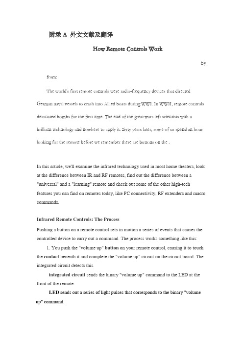
附录A 外文文献及翻译How Remote Controls Workby from:The world's first remote controls were radio-frequency devices that directed German naval vessels to crash into Allied boats during WWI. In WWII, remote controls detonated bombs for the first time. The end of the great wars left scientists with a brilliant technology and nowhere to apply it. Sixty years later, some of us spend an hour looking for the remote before we remember there are buttons on the .In this article, we'll examine the infrared technology used in most home theaters, look at the difference between IR and RF remotes, find out the difference between a "universal" and a "learning" remote and check out some of the other high-tech features you can find on remotes today, like PC connectivity, RF extenders and macro commands.Infrared Remote Controls: The ProcessPushing a button on a remote control sets in motion a series of events that causes the controlled device to carry out a command. The process works something like this:1. You push the "volume up" button on your remote control, causing it to touch the contact beneath it and complete the "volume up" circuit on the circuit board. The integrated circuit detects this.integrated circuit sends the binary "volume up" command to the LED at the front of the remote.LED sends out a series of light pulses that corresponds to the binary "volume up" command.One example of remote-control codes is the Sony Control-S protocol, which is used for Sony TVs and includes the following 7-bit binary commands:Button Code1 000 00002 000 00013 000 00104 000 0011Channel up 001 0000Channel down 001 0001Power on 001 0101Power off 010 1111Volume up001 0010Volume down 001 0011Source:The remote signal includes more than the command for "volume up," though. It carries several chunks of information to the receiving device, including:•a "start" command•the command code for "volume up"•the device address (so the TV knows the data is intended for it) 、•a "stop" command (triggered when you release the "volume up" button)So when you press the "volume up" button on a Sony TV remote, it sends out a series of pulses that looks something like this:Sony TV remotes use a space-coding method in which the length of the spaces between pulses of light represent a one or a zero.When the infrared receiver on the TV picks up the signal from the remote and verifies from the addresscode that it's supposed to carry out this command, it converts the light pulses back into the electrical signal for 001 0010. It then passes this signal to the microprocessor, which goes about increasing the volume. The "stop" command tells the microprocessor it can stop increasing the volume.Infrared remote controls work well enough to have stuck around for 25 years, but they do have some limitations related to the nature of infrared light. First, infrared remotes have a range of only about 30 feet (10 meters), and they require line-of-sight. This means the infrared signal won't transmit through walls or around corners -- you need a straight line to the device you're trying to control. Also, infrared light is so ubiquitous that interference can be a problem with IR remotes. Just a few everydayinfrared-light sources include , and the human body. To avoid interference caused by other sources of infrared light, the infrared receiver on a TV only responds to a particular wavelength of infrared light, usually 980 nanometers. There are filters on the receiver that block out light at other wavelengths. Still, sunlight can confuse the receiver because it contains infrared light at the 980-nm wavelength. To address this issue, the light from an IR remote control is typically modulated to a frequency not present in sunlight, and the receiver only responds to 980-nm light modulated to that frequency. The system doesn't work perfectly, but it does cut down a great deal on interference.While infrared remotes are the dominant technology in home-theater applications, there are other niche-specific remotes that work on radio waves instead of light waves. If you have a garage-door opener, for instance, you have an RF remote.Remote-control FeaturesToday's home-theater remotes do a lot more than turn a component on and off and control the volume. Here are just a handful of the features you can find on some of the higher-tech remote controls out there.Universal capabilitiesDifferent electronics brands use different command codes. Some IR remotes are preprogrammed with more than one manufacturer's command codes so they can operate multiple devices (sometimes up to 15) of different brands. If yourhome-theater setup incorporates components from, say, three different manufacturers, you can either use three different remotes to operate your system or use one universal remote. To add functions to a universal remote, you need to know the command codes for the component you want to control. You can look these up online or find them in the manual that came with your remote.LearningA learning remote can receive and store codes transmitted by another remote control; it can then transmit those codes to control the device that understands them. For instance, let's say you have a receiver with its own preprogrammed remote, and you buy a new TV that comes with a universal learning remote. The learning remote can pick up the signals your receiver remote sends out and remember them so it can control your receiver, too. You don't need to input the command codes yourself -- a learning remote picks up and stores the signals another remote sends out. All learning remotes are considered universal remotes because they can control more than one device.Macro commandsA macro is a series of commands that you program to occur sequentially at the push of a single button. These macros can be anything you want, such as an "activity command." You can set up a macro that lets you push one button to activate, in order, everything that needs to happen for you to watch a movie or listen to a CD. (Some remotes come with "activity commands" preprogrammed, and others let you download macros from the Internet.)PC connectivityThere are remotes that connect to your via the so you can install programming software and download command codes and personalized graphic icons (for remotes with LCD screens).LCD screenA remote-control may simply display data, or it may be a touchscreen that receives user input.User interfacesMost remotes still utilize the simple button-pushing method, but some have more high-tech manners of inputing commands. You'll find remotes that you operate via an LCD , a (for directional commands) and even voice commands.RF extendersSome IR remotes can send out both IR and RF signals. The RF signals aren't meant to control RF devices (in fact, they can't control them). They're meant to extend the operating range of the IR remote control from about 30 feet to about 100 feet (give or take) and allow the signal to penetrate walls and glass cabinet enclosures. The remote automatically transmits both IR and RF signals for every command. When you hook up an RF-to-IR converter (sometimes included with IR/RF remotes, sometimes sold as add-ons) on the receiving end, it receives and converts the signal back into the infrared pulses the device can understand. Now you've got an IR remote that can increase the volume on your home-theater stereo from your bedroom upstairs.Remote controls are steadily increasing the number of devices and functions they can manage. Some universal remotes intended for home-theater components can learn commands for wirelessly controlled lights, so they will not only start a movie at the push of a button, but they'll also dim the lights for you. Full home-automation systems let you use one remote control to manage lighting, alarm systems and entertainment components by way of a receiver wired directly into your home's electrical wiring. Chances are it won't be long before you have a single remote control to manage every electronic device in your life.无线遥控器如何工作著红外遥控工作原理世界上第一个无线遥控器是在一战中以发射无线电波来指引德国海军摧毁盟军的船只。
智能红外传感器中英文对照外文翻译文献
外文翻译中英文对照翻译智能红外传感器跟上不断发展的工艺技术对工艺工程师来说是一向重大挑战。
再加上为了保持目前迅速变化的监测和控制方法的过程的要求,所以这项任务已变得相当迫切。
然而,红外温度传感器制造商正在为用户提供所需的工具来应付这些挑战:最新的计算机相关的硬件、软件和通信设备,以及最先进的数字电路。
其中最主要的工具,不过是新一代的红外温度计---智能传感器。
今天新的智能红外传感器代表了两个迅速发展的结合了红外测温和通常与计算机联系在一起的高速数字技术的科学联盟。
这些文书被称为智能传感器,因为他们把微处理器作为编程的双向收发器。
传感器之间的串行通信的生产车间和计算机控制室。
而且因为电路体积小,传感器因此更小,简化了在紧张或尴尬地区的安装。
智能传感器集成到新的或现有的过程控制系统,从一个新的先进水平,在温度监测和控制方面为过程控制方面的工程师提供了一个直接的好处。
1 集成智能传感器到过程线同时广泛推行的智能红外传感器是新的,红外测温已成功地应用于过程监测和控制几十年了。
在过去,如果工艺工程师需要改变传感器的设置,它们将不得不关闭或者删除线传感器或尝试手动重置到位。
当然也可能导致路线的延误,在某些情况下,是十分危险的。
升级传感器通常需要购买一个新单位,校准它的进程,并且在生产线停滞的时候安装它。
例如,某些传感器的镀锌铁丝厂用了安装了大桶的熔融铅、锌、和/或盐酸并且可以毫不费力的从狭窄小道流出来。
从安全利益考虑,生产线将不得不关闭,并且至少在降温24小时之前改变和升级传感器。
今天,工艺工程师可以远程配置、监测、处理、升级和维护其红外温度传感器。
带有双向RS - 485接口或RS - 232通信功能的智能模型简化了融入过程控制系统的过程。
一旦传感器被安装在生产线,工程师就可以根据其所有参数来适应不断变化的条件,一切都只是从控制室中的个人电脑。
举例来说,如果环境温度的波动,或程序本身经历类型、厚度、或温度的改变,所有过程工程师需要做的是定制或恢复保存在计算机终端的设置。
无线红外通信-外文翻译
原文:Wireless Infrared CommunicationsI. IntroductionWireless infrared communications refers to theuse of free-space propagation of light waves in thenear infrared band as a transmission medium forcommunication(1-3), as shown in Figure 1. The communication can be between one portable communication device and another or between a portable device and a tethered device, called an access pointor base station. Typical portable devices includelaptop computers, personal digital assistants, andportable telephones, while the base stations are usually connected to a computer with other networkedconnections. Although infrared light is usually usedother regions of the optical spectrum can be used (sothe term wireless optical communications" insteadof wireless infrared communications" is sometimesused).Wireless infrared communication systems can becharacterized by the application for which they aredesigned or by the link type, as described below.A.ApplicationsThe primary commercial applications are as follows:²short-term cable-less connectivity for informationexchange (business cards, schedules, file sharing) between two users. The primary example is IrDA systems (see Section 4).²wireless local area networks (WLANs) provide network connectivity inside buildings. This can eitherbe an extension of existing LANs to facilitate mobility, or to establish “ad hoc”networks where there isno LAN. The primary example is the IEEE 802.11standard (see Section 4).²building-to-building connections for high-speednetwork access or metropolitan- or campus-area net-works.²wireless input and control devices, such as wirelessmice, remote controls, wireless game controllers, andremote electronic keys.B. Link TypeAnother important way to characterize a wirelessinfrared communication system is by the “link type”which means the typical or required arrangement ofreceiver and transmitter. Figure 2 depicts the twomost common configurations: the point-to-point system and the diffuse system.The simplest link type is the point-to-pointsystem. There, the transmitter and receiver must bepointed at each other to establish a link. The line-of-sight (LOS) path from the transmitter to the receivermust be clear of obstructions, and most of the transmitted light is directed toward the receiver. Hence,point-to-point systems are also called directed LOS systems. The links can be temporarily created for adata exchangesession between two users, or established more permanently by aiming a mobile unit ata base station unit in the LAN replacement application.In diffuse systems, the link is always maintainedbetween any transmitter and any receiver in the samevicinity by reflecting or |“bouncing”the transmittedinformation-bearing light off reflecting surfaces suchas ceilings, walls, and furniture. Here, the transmitter and receiver are non-directed; the transmitteremploys a wide transmit beam and the receiver hasa wide field-of-view. Also, the LOS path is not required. Hence, diffuse systems are also called non-directed non-LOS systems. These systems are wellsuited to the wirelessLAN application, freeing theuser from knowing and aligning with the locations ofthe other communicating devices.C. Fundamentals and OutlineMost wireless infrared communications systemscan be modeled as having an output signal Y (t) andan input signal X(t) which are related bywhere denotes convolution, C(t) is the impulse response of the channel and N(t) is additive noise.This article is organized around answering key questions concerning the system as represented by thismodel.In Section 2, we consider questions of optical design. What range of wireless infrared communications systems does this model apply to? How does C(t) depend on the electrical and optical properties ofthe receiver and transmitter? How does C(t) dependon the location, size, and orientation of the receiverand transmitter? How do X(t) and Y (t) relate to optical processes? What wavelength is used for X(t)?What devices produce X(t) and Y (t)? What is thesource of N(t)? Are there any safety considerations?In Section 3, we consider questions of communications design. How should a data symbol sequence bemodulated onto the input signal X(t)? What detection mechanism is best for extracting the informationabout the data from the received signal Y (t)? Howcan one measure and improve the performance of thesystem? In Section 4, we consider the design choicesmade by existing standards such as IrDA and 802.11.Finally, in Section 5, we consider how these systemscan be improved in the future.II. Optical DesignA. Modulation and demodulationWhat characteristic of the transmitted wave willbe modulated to carry information from the transmitter to the receiver? Most communication systemsare based on phase, amplitude, or frequency modulation, or some combination of these techniques.However, it is difficult to detect such a signal following nondirected propagation, and more expensivenarrow-linewidth sources are required(2). An effective solution is to use intensity modulation, wherethe transmitted signal's intensity or power is proportional to the modulating signal.At the demodulator (usually referred to as a detector in optical systems) the modulation can be extracted by mixing the received signalwith a carrierlight wave. This coherent detection technique is bestwhen the signal phase can be maintained. However,this can be difficult to implement and additionally, innondirected propagation, it is difficult to achieve therequired mixing efficiency. Instead, one can use directdetection using a photodetector. The photodetectorcurrent is proportional to the received optical signalintensity, which for intensity modulation, is also theoriginal modulating signal. Hence, most systems useintensity modulation with direct detection (IM/DD)to achieve optical modulation and demodulation.In a free-space optical communication system, thedetector is illuminated by sources of light energyother than the source. These can include ambientlighting sources, such as natural sunlight, fluorescent lamp light, and incandescent lamp light. Thesesources cause variation in the received photocurrentthat is unrelated to the transmitted signal, resultingin an additive noise component at the receiver.We can write the photocurrent at the receiver aswhere R is the responsivity of the receiving photodiode (A/W). Note that the electrical impulse responsec(t) is simply R times the optical impulse responseh(t). Depending on the situation, some authors use(t) and some use h(t) as the impulse response.B. Receivers and TransmittersA transmitter or source converts an electrical signal to an optical signal. The two most appropriatetypes of device are the light-emitting diode (LED)and semiconductor laser diode (LD).LEDs havea naturally wide transmission pattern, and so aresuited to nondirected links. Eye safety is much simpler to achieve for an LED than for a laser diode,which usually have very narrow transmit beams.The principal advantages of laser diodes are theirhigh energy-conversion efficiency, their high modulation bandwidth, and their relatively narrow spectral width. Although laser diodes offer several advantages over LEDs that could be exploited, mostshort-range commercial systems currently use LEDs.A receiver or detector converts optical power intoelectrical current by detecting the photon flux incident on the detector surface. Silicon p-i-n photodiodes are ideal for wireless infrared communications asthey have good quantum efficiency in this band andare inexpensive(4). Avalanche photodiodes are notused here since the dominant noise source is back-ground light-induced shot noise rather than thermalcircuit noise.C. Transmission W avelength and NoiseThe most important factor to consider whenchoosing a transmission wavelength is the availability of effective, low-cost sources and detectors. Theavailability of LEDs and silicon photodiodes operating in the 800 nm to 1000 nm range is the primaryreason for the use of this band. Another importantconsideration is the spectral distribution of the dominant noise source: background lighting.The noise N(t) can be broken into four components: photon noise or shot noise, gainnoise, receiver circuit or thermal noise, and periodic noise.Gain noise is only present in avalanche-type devices,so we will not consider it here.Photon noise is the result of the discreteness ofphoton arrivals. It is due to background lightsources, such as sun light, fluorescent lamplight,and incandescent lamp light, as well as the signaldependent source X(t) - c(t). Since the backgroundlight striking the photodetector is normally muchstronger than the signal light, we can neglect the dependency of N(t) on X(t) and consider the photonnoise to be additive white Gaussian noise with two-sided power spectral density where qis the electron charge, R is the responsivity, and Pnis the optical power of the noise (background light).Receiver noise is due to thermal effects in the receiver circuitry, and is particularly dependent on thetype of preamplifier used. With careful circuit design, it can be made insignificant relative tothe photon noise(5).Periodic noise is the result of the variation of fluorescent lighting due to the method of driving thelamp using the ballast. This generates an extraneous periodic signal with a fundamental frequency of44 kHz with significant harmonics to several MHz.Mitigating the effect of periodic noise can be doneusing high-pass filtering in combination with baselinerestoration(6), or by careful selection of the modulation type, as discussed in Section 3.1.D. SafetyThere are two safety concerns when dealing withinfrared co mmunication systems. Eye safety is a concern because of a combination of two effects: thecornea is transparent from the near violet to the nearIR. Hence, the retina is sensitive to damage from light sources transmitting in these bands. However,the near IR is outside the visible range of light, andso the eye does not protect itself from damage byclosing the iris or closing the eyelid. Eye safety canbe ensured by restricting the transmit beam strengthaccording to IEC or ANSI standards(7,8).Skin safety is also a possible concern. Possibleshortterm effects such as heating of the skin are accounted for by eye safety regulations (since the eyerequires lower power levels than the skin). Longtermexposure to IR light is not a concern, as the ambientlight sources are constantly submitting our bodies tomuch higher radiation levels than these communication systems do.III. Communications DesignEqually important for achieving the design goals ofwireless infrared systems are communications issues.In particular, the modulation signal format togetherwith appropriate error control coding is critical toachieving power efficiency. Channel characterizationis also important for understanding performance limits.A. Modulation TechniquesTo understand modulation in IM/DD systems, wemust look again at the channelmodeland consider its particular characteristics. First,since we are using intensity modulation, the channel input X(t) is optical intensity and we have theconstraint X(t). The average transmitted optical power PT is the time average of X(t). Our goalis to minimize the transmitted power required to attain a certain probability of bit error Pe, also knownas a bit error rate (BER).It is useful to define the signal-to-noise ratio SNRaswhere H(0) is the d.c. gain of the channel, i.e. itis the Fourier transform of h(t) evaluated at zerofrequency, soThe transmitted signal can be represented asThe sequence represents the digital informationbeing transmitted, whereis one of L possible datasymbols from 0 to L-1. The function Si(t) representsone of L pulse shapes with duration Ts, the symboltime. The data rate (or bit rate) Rb, bit time T,symbol rate Rs, and symbol time Ts are related asfollows:.There are three commonly used types of modulation schemes: on-off keying (OOK) with non-return-to-zero pulses, OOK with return-to-zero pulses ofnormalized width and pulse position modulation with L pulses (L-PPM). OOK and aresimpler to implement at both the transmitter and receiver than L-PPM. The pulse shapes for these modulation techniques are shown in Figure 3. Representative examples of the resulting transmitted signalX(t) for a short data sequence areshown in Figure4.We compare modulation schemes in Table 1 bylooking at measures of power efficiency and bandwidth efficiency. Bandwidth efficiency is measuredby dividing the zero-crossing bandwidth by the datarate. Bandwidth efficient schemes have severaladvantages—the receiver and transmitter electronicsare cheaper, and the modulation scheme is less likelyto be affected by multipath distortion. Power efficiency is measured by comparing the required transmit power to achieve a target probability of error Pefor different modulation techniques. Both andPPM are more power efficient than OOK, but at thecost of reduced bandwidth efficiency. However, for agiven bandwidth efficiency, PPM is more power efficient than,and so PPM is most commonlyused. OOK is most useful at very high data rates,say 100 Mb/s or greater. Then, the effect of multipath distortion is the most significant effect andbandwidth efficiency becomes of paramount importance(9).B. Error Control CodingError control coding is an important technique forimproving the quality of any digital communicationsystem. We concentrate here on forward error correction channel coding, as this specifically relates to wireless infrared communications; source coding andARQ coding are not considered here.Trellis-coded PPM has been found to be an effective scheme for multipath infrared channels(10,11).The key technique is to recognize that although ona distortion-free channel, all symbols are orthogonal and equidistant in signal space, this is not trueon a distorting channel. Hence, trellis-coding usingset partitioning designed to separate the pulse positions of neighboring symbols is an effective codingmethod. Coding gains of 5.0 dB electrical have beenreported for rate 2/3-coded 8-PPM over uncoded 16-PPM, which has the same bandwidth(11).C. Channel impulse response characterizationImpulse response characterization refers to theproblem of understanding how the impulse response C(t) in Equation (1) depends on the location, size,and orientation of the receiver and transmitter.There are basically three classes of techniques foraccomplishing this: measurement, simulation, andmodeling. Channel measurements have been described in several studies(9,12,2), and these formthe fundamental basis for understanding the channel properties. A particular study might generate a collection of hundreds or thousands of example impulse responses Ci(t) for configuration i. The collection of measured impulse responses Ci(t) can thenbe studied by looking at scatter plots of path lossversus distance, scatter plots of delay spread versusdistance, the effect of transmitter and receiver orientations, robustness to shadowing, and so on.Simulation methods have been used to allow directcalculation of a particular impulse response based ona site-specific characterization of the propagation environment(13,14). The transmitter, receiver, and thereflecting surfaces are described and used to generatean impulse response. The basic assumption is thatmost interior surfaces reflect light diffusely in a Lambertian pattern, i.e. all incident light, regardless ofincident angle, is reflected in all directions with anintensity proportional to the cosine of the angle ofthe reflection with the surface normal. The difficultywith existing methods is that accurate modeling requires extensive computation.A third technique attempts to extract knowledge gained from experimental and simulation-basedchannel estimations into a simple-to-use model. In (15), for example, a model using two parameters (onefor path loss, one for delay spread) is used to providea general characterization of all diffuse IR channels.Methods for relating the parameters of the modelto particular room characteristics are given, so thatsystem designers can quickly estimate the channelcharacteristics in a wide range of situations.翻译:无线红外通信I.导言无线红外通信指的是使用近红外波段的光作为通信传输介质的一种通讯方式(1-3),如图1所示。
外文翻译原文--基于红外报警技术的防盗系统
Based on infrared alarm technology security systems1the introduction1.1the research significance of this topic research situation at home and abroad.With the development of society and science and technology unceasing development,people's living standards been improved greatly,and to the private property protection means in the unceasing enhancement,the intelligent facilities for anti-theft puts forward new requirements.This design is to meet the need of modern residential anti-theft designed family electronic alarm system.It in previous devices based on improved greatly, because use the single-chip processor signal,not only can used for single residential area,also can be used in a large-scale residential security systems.It's the job of the performance is good,do not appear to report and misstatement phenomenon,safe and reliable.In our country,the present market condition alarm basically has triggered alarm system pressure switch electron and alarm system and pressure shading triggered alarm system,etc.Various kinds of alarm,but this several common alarm there are some shortcomings.This system USES a human pyroelectric infrared sensor in the human body detector in the field, passive pyroelectric infrared detectors because of its low cost,easy fabrication,low cost,installation is more convenient,anti-theft performance is stable and high sensitivity,safe and reliable,has attracted broad family characteristics such as popular with the customers. And alarms installation concealment,not easily by rogue found.1.2infrared alarm technology introductionInfrared sensing technology can be divided into active sensing technology and passive sensing technology.Therefore infrared alarm is divided again active infrared alarm and passive infrared alarm.1.2.1active alarm technologyActive infrared alarm is by sending and receiving device two parts. Infrared transmitter drive infrared light emitting diode modulation issued a bunch of the infrared beam.In a certain distance from the transmitter, and placed in a infrared receiver alignment.It through the photo transistor receiving launch end issued ir radiation energy,and pass byphotoelectric convert to electrical signals.This signal after proper treatment again sent alarm controller circuit.Respectively in charge and inchoative place a infrared optical lenses,will be gathered into fine parallel beams,in order to make the infrared energy can concentrate ing the infrared light modulation has the following advantages:(1)reduce power consumption.(2)make infrared detector has strong resistance to?1.2.2passive quote with technologyPassive infrared detector does not need additional infrared radiation lamp-house,itself not to external launch any energy,but by directly from a moving target detection probe the infrared radiation,so just have passive said.Passive infrared detector is with pyroelectricity effect on detecting.1.2.2.1nature objects of the infrared radiationThe nature of any object,as long as the temperature above absolute zero (273℃),constantly outward issued infrared radiation,and travel at the speed of light energy.Object radiate outward infrared radiation of energy and the object of temperature and infrared radiant wavelength.Assuming objects launching infrared radiation of peak wavelength for a few,,its temperature for T,the radiation energy equals infrared radiation of peak wavelength gerben and object product temperature T.This product is a constant,namely:The higher the temperature of the objects,emit infrared radiation of the smaller peak wavelength,send out infrared radiation energy is bigger also.1.2.2.2pyroelectric effectPassive infrared detector also called pyroelectric infrared detector,its main working principle is pyroelectric effect.Pyroelectric effect means if make some strong dielectric material(such as qin batio3,qin wrong acid lead P(zT),etc.)of the surface temperature changes,then with the temperature rise or fall,material surface occurs polarization,namely onthe surface of the charge will be produced change,and material surface charge lost balance and eventually charge will change with voltage or current form output.In pyroelectric infrared detectors are two key components,one is pyroelectric infrared sensor P(TR),infrared signal changes can be theptr shift into electrical signal to the white light signal has a natural inhibition.Another is the Fresnel lens,?Fresnel thoroughly1.2.2.3pyroelectric infrared sensor basic structurePyroelectric infrared sensors from sensor detection yuan,interference filters and mosfet verifier three parts.According to the number of detecting yuan to points,pyroelectric infrared sensors have unit,double yuanhe four yuan to wait for a few kinds,for human detection of infrared sensor adopts double yuan or four yuan type structure.According to pyroelectric infrared sensor utility cent,have the following kinds:used for measuring temperature sensor,it's the job of the wavelength of(1-20) nano,Used for flame detection sensor,it's the job of the wavelength for 0.435+/-0.15nano,For human detection sensor,it's the job of the wavelength of7to15feet.Figure 1.2is a double detection yuan pyroelectric infrared sensor structure schematic drawing.The sensor will two opposite polarity,specialWhen using general in the tube and shell capped with filter of films and window,to choose receive different wavelengths.In the window jacket filter is designed to make don't need infrared sensors cannot enter. General pyroelectric infrared sensor in spectral range sensitivity is quite flat(and not being visible effect).Usually used siliceouspolyethylene material filter,it can not contact form detect objects to radiate the infrared energy changes,and converts it into electrical signal output.Sensor probe the Fresnel lens with front.The Fresnel lens is with transparent made of plastic with a special optical coefficient of lenses, it consists of a set of parallel prism type lens is composed of its each unit is only a little of the lens,?view AngleWhen someone from the lens body before walked out of the infrared ray unceasingly in the"blind"and"high sensitive areas]switch,it makes received signals to suddenly strong suddenly weak pulse form input, strengthened the energy changes amplitude,thereby improving the detection sensitivity.1.2.2.4pyroelectric infrared detector basic principlePyroelectric infrared sensor by receiving mobile human radiation that certain wavelengths of infrared radiation,can be transformed into and human body movement speed and distance,the direction of low-frequency signals about.When pyroelectric infrared sensor by ir radiation sources of radiation,its internal sensitive materials temperatures will rise, polarization intensity is abate,surface charge reduce,usually will release this part of the charge called pyroelectric charge.Because of pyroelectric charge how many can reflect material changes of temperature, so by pyroelectric charge by circuit transformed into the output voltage can also reflect material changes in temperature,thus detect ir radiation energy changes.The optical system of the infrared detector can be more than?from2hardware system design2.1infrared anti-theft alarm system hardware designBecause this design focuses on family guard against theft,real-time monitoring of a narrower range,so this design by simply using a passive infrared detector is enough.Therefore,infrared intelligent anti-theft alarm system,and the specific design requirements for:1completes to high sensitive infrared sensor design,make its can warning of what happened real-time and accurate detection.2automatic alarm(automatic dial-up alarm audible and visual alarm). We design the system must have the following function module:3passive infrared detector,4sound-light alarm,5telephone automatic dial-up function;6continued uninterrupted power supply,According to the system to complete functions,we adopt single chip microcomputer as the core of the system unit,electronic detection, intelligent control and telephone tong2.2telephone automatic dial-up alarm circuit designIn order to simplify the whole system design process,we do not adopt MT880 chip dialing.Realization process is as follows:First in telephone storage inside put on domestic host cell phone number or alarm call110.From MCU pins p2.0and p2.1drawn two wiring connect relays,a pick telephone keyboard MianDiJian,another connect telephone keyboard keys,automatic weighing dial because the phone keypad scanning is similar microcontroller keypad scanning,so can make SCM give first p2.0 a signal,lets telephone h-f,then give the p2.1a signal,let relay connected,automatic weighing dial the key a potential,let telephone automatic dial-up,so they could finish the system alarm function.2.3system working principleThe whole system hardware part mainly includes six parts:MCU module; Infrared detector,Acousto-optic alarm circuit;Telephone automatic dial-up alarm circuit;Power supply circuit,Working state instructions circuit.Its system working principle for:the sensors will be detected signals to lead signal processor processing,microcontroller judgment to P1.0mouth have pulse falling edge jumping signal immediately transferred to the acousto-optic alarm program,at this moment,the red light buzzer alarm rapid flashes,lasted30s.In the30s inside if someone press the switch,then eliminate alarm remove alarm.If this time no one remove alarm, the proof nobody at home in30s system will automatically triggers telephone finish the whole system of police work ter, microcontroller will continue to cycle back?sentenced3.4system total diagramIn proteus simulation system,the system circuit by crystals circuit, sound-light alarm circuit composed.Among them,we use connect the dedication of the P1.0simulated infrared sensors,requirement when switch when pressed by the high jump,level is low,the equivalent of,sensor detects the state of man,the telephone line with P2.0and P2.1derivation, here without simulation telephone circuit diagram.Figure 3.53software system design3.1control module design programMicrocomputer in the initial plus electric,voltage is not steady state, causing instability,at this time the SCM in commonly after power up to system with a piece of delay.Time-lapse after detecting P1mouth microcontroller state,detection level signal whether mutations,if is then calls the police processing procedure,including automatic dial-up audible and visual alarm procedures,if no changes,ChuXiang leveldetection continues to P1mouth state.Figure 4.1main program flowchart3.2system development adopted by the programming and commissioning of the platformThis system language using assembly language preparation,so choose wave6000,he has the microcontroller program edit,compile and debugging, etc.,and generate hexadecimal.Files,through:machine TOPWIN burning software writeable microcontroller program memory.The simulation software use Proteus,he is from Britain Labcenter electronics company EDA software.The circuit of the simulation is interactive,aiming at the microprocessor application,still can directly based on schematic diagram of the virtual prototype programming,and implementing software source code level of real-time debugging,if have display and output,still can see after the operation of input and output effect.4system debugging and test4.1software debuggingAdopt modularization program design thought,first debugging subroutines, then gradually superposition debugging,through Proteus simulation software debugging,proof program can realize its function.4.2system debuggingThrough the circuit of welding,each module function commissioning.I put the hardware that occur errors adjusted,in addition,infrared that piece, because is employing redirected of pyroelectric switch modified,so in must be taping photoconductive resistance to rise,has arrived in the days and nights can alarm function.The total system commissioning,through,error meets the requirement.5closingThis system USES a pyroelectric infrared sensor,its make simple low cost and installation are more convenient and anti-theft performance is stable and strong anti-jamming capability,high sensitivity,safe and reliable. In addition,the system also has the very big function expansion,for example,in the warehouse,community or monitoring range is wider place, can add a few road infrared detector,using interface communication technology and computer connection,be helpful for the unified administration.Doing single family anti-theft system,we can also add LCD module,display alarming time,add more keyboard locks,let family or friends know the password of cases remove alarm,in case the misstatement occur).。
红外遥控系统毕业论文外文文献翻译
红外遥控系统毕业论文外文文献翻译Infrared Remote Control SystemAbstractRed outside data correspondence the technique be currently within the scope of world drive extensive usage of a kind of wireless conjunction technique,drive numerous hardware and software platform support. Red outside the transceiver product have cost low, small scaled turn, the baud rate be quick, point to point SSL, be free from electromagnetism thousand Raos etc.characteristics, can realization information at dissimilarity of the product fast, convenience, safely exchange and transmission, at short distance wireless deliver aspect to own very obvious of advantage.Along with red outside the data deliver a technique more and more mature, the cost descend, red outside the transceiver necessarily will get at the short distance communication realm more extensive of application.The purpose that design this system is transmit customer’s operation information with infrared rays for transmit media, then demodulate original signal with receive circuit. It use coding chip to modulate signal and use decoding chip to demodulate signal. The coding chip is PT2262 and decoding chip is PT2272. Both chips are made in Taiwan. Main work principle is that we provide to input the information for the PT2262 with coding keyboard. The input information was coded by PT2262 and loading to high frequent load wave whose frequent is 38 kHz, then modulate infrared transmit dioxide and radiate space outside when it attian enough power. The receive circuit receive the signal and demodulate original information. The original signal was decoded by PT2272, so as to drive some circuit to accomplishcustomer’s operation demand.Keywords:Infrare dray;Code;Decoding;LM386;Redoutside transceiver1 Introduction1.1 research the background and significanceInfrared Data Communication Technology is the world wide use of a wireless connection technology, by the many hardware and software platforms supported. Is a data through electrical pulses and infrared optical pulse switch between the wireless data transceiver technology.Infrared transceiver products with low cost, small, fast transmission rate, the point-to-point transmission security, not subject to electromagnetic interference and other characteristics that can be achieved between the different products, rapid, convenient and safe exchange and transmission, In short distance wireless transmission have a very distinct advantage.Infrared transceiver products in the portable product of a great role. At present, the world's 150 million piece of equipment used infrared technology in electronic products and industrial equipment. medical equipment and other fields widely used. For example, 95% of the notebook computers on the installation of infrared transceiver interface the majority of the cell phone is also the allocation of infrared transceiver interface. With the exchange of quantitative data, infrared data communications will enable cell phone data transmission more convenient. With infrared data transmission technology matures, perfect, low costs, Infrared Transceiver in short distance communications will be more widely applied.This chapter first describes the infrared transceiver IC design issues to the background and significance. then briefed theinfrared data communications technology features and applications, and infrared transceiver product characteristics, domestic and international situation and development trend of the last under infrared remote transceiver system in practical application to establish a task of design orientation.1.2 Infrared Remote ControlTransceiver SystemInfrared remote control system is divided into single-channel and multi-channel remote control. Only a command signal transmission channel, called single-channel remote control system; with more than two instructions signal transmission channel known as a multi-channel remote control system. Relatively simple single-channel remote control, in general, only a launcher directive Key receivers and only one circuit implementation. While in the receiving circuit to add more stable memory circuits that can be activated commands to launch a number of key, so that the receiver circuit multistable memory circuit repeatedly to change the state, to realize many of the functional control, But such a state of change is the order. If we are to achieve an arbitrary control, resort to the use of multi-channel remote control system. Multi-channel remote control can be realized by the object of arbitrary multi-function remote control. As for the choice of several routes and what control methods, according to the actual situation (such as object, operational requirements and cost accounting, etc.) to decide. General infrared remote transceiver system by infrared remote control transmitter signal coding, infrared remote control signal receivers and decoders (or decoder chip MCU) and the external circuit consisting of three parts. Signal transmitter remote control code used to generate pulses of infrared emission-driven output infrared remote control signal, receiver completion of the remotecontrol signal amplification and detection, plastic and demodulation encoding pulse. Infrared remote control coded pulse is going to obtain a continuous serial binary code, and for most of the infrared transceiver system, This serial code as micro-controller of the remote control input signals from the internal CPU completion of the remote control instruction decoder, on the other infrared remote control transceivers, the designers of electronic products, The internal micro-controller of the remote control decoder directive is not accessible.Therefore, people are using infrared encoder / decoder chip and microcontroller developed various generic infrared remote transceiver system, In various equipment infrared signals between the transceiver.Remote transceiver system generally transmitters and receivers is composed of two parts. Launchers from the general direction keys, coded instructions circuit modulation circuit, driving circuit, firing circuit of several parts. When pressed a key, the directive coding circuit, in the corresponding instructions encoded signal, the encoder signal to the carrier modulation, Driven by the power amplifier circuit after circuit fired from the field after firing instructions coded modulation signals. General receiver by the receiving circuit, the amplifier circuit, demodulation circuits, instruction decoder circuit, driving circuit, circuit implementation of several parts. Receiving Circuit will launch vehicles have been coded modulation signal receiving instructions from, and to enlarge evacuation demodulation circuit. Demodulation circuit will have the coding modulation signal demodulation, namely, reduction of signal coding. The instruction decoder to the encoder signal decoding, Driven by the final circuit to drive the implementation of variousinstructions circuit to control the operation.1.3 infrared remote control transceiver product profiles 1.3.1 infrared remote control transceiver product structure and type Currently infrared transceiver in accordance with the mode of transmission rate and can be divided into four categories : Serial mode, the highest rate of 115.2 Kbps; medium-speed model : the highest rate of 0.567 Mbps and 1.152Mbps; High-speed mode : The maximum rate of 16 Mbps.Also according to the size chip power consumption can be divided into low-power consumption and standard two categories, low-power type normally used 3 V power supply, transmission distance closer to about 0 - 30cm, which is commonly used standard 5V power supply, transmission distance away at least 1mabove.1.3.2 infrared remote control transmitters of the status quo at home and abroadInfrared communication technology in the development stage and there are several infrared communication standards, between different standards for infrared equipment can not infrared communication. To have all the infrared equipment to interoperability in 1993 by more than 20 large manufacturers initiated the establishment of an Infrared Data Association (IRDA) unified the infrared communication standards , which is currently widely used in infrared data communication protocols and standards, also known as the IRDA standard.Since 1993 IRDA since the establishment of the Infrared Data Association members have developed to more than 150. IRDA standards of the industry has been widely recognized and supported. Has been developed with the infraredcommunications equipment have been as many as 100 species. IR module, installed capacity has reached 150 million sets. Although there is also a short distance wireless Bluetooth technology, But in infrared communication technology low cost and broad compatibility advantages, Infrared data communication in the future will still be a very long time inherent short-range wireless data communications fields play an important role.1.3.3 Infrared Transceiver product development trendIn various infrared transceiver products, although the transmission rate, transmission distance and other characteristics, But infrared transceiver products has been towards improving the transmission rate, increase the transmission distance and lower power consumption, expanding launch reception angle of development. In particular, as the technology development and maturity, the means of transmission is moving in the direction of point-to-multipoint. Therefore infrared remote control transceiver products have broader prospects for development.2 Infrared communication of knowledge2.1 infrared ray foundation knowledge2.1.1 infrared outlinedInfrared is actually a kind of electromagnetic wave. From the analysis of various natural component of the electromagnetic wave reflected spectrum is :-ray, x-ray, ultraviolet, visible, infrared, microwave and radio wave. From the viewpoint of form, and they did not seem to, but if the wavelength in descending order, and we will find him all the only visible light spectrum of the entire 0.38 μm - 0.76μm so long little area, and adjacent to the visible light and infrared (including the far infrared, mid-infrared and near infrared foreign) accounts for the spec trum of 0.76 μm -1000μm of a major. Which micron wavelength range also includes UV, visible, near infrared, mid-infrared and far-infrared, microwave.From the above analysis shows that infrared is a very rich spectrum resources, it currently has in production, life, military, medical, and other aspects have been widely used, such as infrared heating, medical infrared, infrared communication, infrared camera, infrared remote control, and so on. Infrared remote control is the many applications of infrared part of the current household appliances widely used in TV remote control, VCR remote control, VCD remote control, high-fidelity audio remote control, are used infra-red remote control, It allows the control of these appliances have become very easy.2.1.2 infrared propertiesInfrared lies between visible light and microwave a wave, it is with certain clinical characteristics of the wave. In the near-infrared, visible light and its adjacent, it is visible in certain characteristics, such as straight-line transmission, reflection, refraction, scattering, diffraction, can be certainobjects and can be absorbed through the lens of their focusing. In the far-infrared region, owing to its neighboring microwave, it has some characteristics of microwave, If a strong penetrating power and can run through some opaque substances. Since in any object, natural profession, regardless of whether its own luminescence (referring to visible light), as long as the temperature is above absolute zero (-273 °C), moment will be kept around to infrared radiation. Only higher temperature of objects strong infrared radiation, low-temperature objects infrared radiation weaker. Therefore infrared feature is the greatest common in nature, it is called thermal radiation calledthermal radiation. Infrared cameras, infrared night market pyroelectric infrared detectors and some other missiles aiming at is the use of this characteristic of infrared work.Infrared and visible light compared to another characteristic of a variety of colors. As the longest wavelength of visible light is a wavelength of the shortest times (780 nm-380 nm), So is called an octave. And infrared wavelength is the longest shortest wavelength of a times, and the longest wavelength infrared is the shortest wavelength of 10 times, that is, 10 octave. Therefore, if visible light can be expressed as seven colors, infrared may performance 70 colors, showing the rich colors. Infrared smoke through the good performance, which is also one of its features.Because not visible to the infrared, it has little effect on the environment. By the wave infrared rays than the long wavelength radio waves, infrared remote control will not affect the nearby radio equipment. Another wavelength of less than 1.5μm near infrared light, transparent atmosphere in the visible light transmission characteristics much better than, because it close to the visible edge of the red light, linear transmission, reflection, refraction and absorption material and the physical characteristics very similar to visible light. Therefore, it can be used with similar visible focusing lens and other optical devices. Because infrared remote control is not as remote as the radio through the barrier to control the object's ability to control, so in the design of household appliances infra-red remote control, wireless remote control as unnecessary, each set (transmitters and receivers) have different frequency or remote coding (Otherwise, wall will control or interference with neighbors household appliances), all similar products in the infrared remote control, The same can control the frequency orcoding, and no remote control signal "drop." This universal infrared remote control provides a great convenience. Infrared to visible light, is very subtle and confidentiality, therefore, the security, Alert and other security devices have been widely used. Infrared remote control is simple in structure and easy, low-cost, anti-interference capability, high reliability are a number of advantages, is a close-up remote control, especially in indoor remote control optimized manner.2.1.3 infrared diode characteristicsInfrared is not visible, people here are not aware of. Electronic technology is used infrared light emitting diode (also known as the IR emission diode) to generate infrared. Infrared remote control transceiver is using near-infrared transmission control instructions 0.76μm wavelength of ~ 1. 5μm. Near-infrared remote control as a light source, because there infrared light emitting diodes and infrared receiving device (photodiode. Transistor and PV) and the luminescence peak wavelength of light by the general 0.8μm ~ 0. 94μm. in the near-infrared band, both of the spectrum is the coincidence to a good match, access to higher transmission efficiency and higher reliability. Commonly used infrared diode, and its shape is similar LED light emitting diodes, Its basic circuit shown in figure 2 -2. The triode plans for the switch, when the base added a driving signal, Transistor saturated conduction infrared LED D is also Wizard Lin k, issued infrared (near infrared about 0.93 μm). D.The pressure drop of about 1.4 V and the current general for 10-20mA. To adapt to the working voltage of the D loop resistance often as a series of infrared diode current limit resistance.When the circuit diagram of the infrared emission controlcorresponding to the controlled device, the control of the distance and D is proportional to the transmitting power. In order to increase the distance of infrared control, infrared diode D should work on the pulse state that work is the lifeblood of current. Because pulse light (optical modulation) the effective transmission distance and pulse is proportional to the peak current, only maximize peak current Ip, will increase the infrared distance. Ip increase is a way to reduce the pulse duty cycle, that is compressed pulse wi dth τ some TV infrared remote control, its infrared luminescence of the pulse duty cycle of about 1/4-1/3; Some electrical products infrared remote control, its duty cycle of 1 / 10. Decreasing pulse duty cycle also enable low-power infrared LED distance of the greatly increased. Common infrared light emitting diodes, power is divided into small power (1 mW - 10mW). Chinese power (20mW - 50mW) and power (50mW - 100mW more) three categories. Use different power infrared LED, the allocation should be driven by the corresponding power control. Figure 2 -2 by the reflected infrared light-emitting diodes to make produce optical modulation, Drivers only need to add the control of a certain frequency pulse voltage.Infrared transmitter and receiver in the way the two kinds of straight, and the second is reflective. Luminescence pointed straight pipe and tube receiver placed in a relatively controlled and fired on the two ends, a certain distance away from the middle; Reflective means luminescent tube and pipe parallel with the receiving peacetime, without always receiving tube light, luminescence only in possession of the infrared light reflected fromencountered, the receiving tube received from the reflected infrared before work.2.2 infrared communication basic tenets2.2.1 infrared communication PrincipleCommunication is the use of infrared wavelength of 900 nm-infrared waves from 1000 to serve as an information carrier, through infrared technology between the two close communication and confidentiality of information transmitted. Infrared communication system structure include : part launcher, channel, the receiver part.Launcher source letter issued after the binary signal from the high-frequency modulated infrared LED sent, receiving device regard the reception of high-frequency signals from the infrared receiver tube after receiving further demodulation photoelectric conversion of the original information of a mass communication lose way. Afterwards the former Information received after receiving part of the drive circuit connected to the expected completion of the various functions. To which the modulation coding style pulse width modulation (by changing the pulse width modulated signal PWM) and pulse modulation time (through change the pulse train interval time between the modulation signal PPM) two.2.2.2 infrared communication system elements(1) Launches : Currently there is a infrared wireless digital communications system sources of information including voice, data, images. Its methods of work for the launch of the receiver can be divided into different layout LOS way (Light-of-Sight , intracardiac way), diffuse (diffuse) mode. LOS way directional, it has good channel characteristics such advantages, but the existence of a "shadow" effect. difficult to achieve roaming function. Roaming means the main features of non-directional, and easy to implementroaming function, but its channel quality is better sometimes LOS way. Transmission of signals required for a few of (the sampling was quantified), the general need for baseband modulation, transmission, modulation, sometimes signal source coding, the above-driven signals from photoelectric converter complete optical signal transmission. Infrared wireless digital communications system and its scope of work-for-fired power distribution, the quality of the communication. While using various methods to improve optical transmitter power, the other using spatial diversity, holographic films and so on so diffuse light for the launch of space optical power evenly distributed.(2) Channel : infrared wireless digital communication channel refers to the transmitters and receivers in the space between. Due to natural light and artificial light sources such as light signals in the context of intervention, and the source - Electrical Equipment, The optical noise and disturbances, infrared wireless digital communications in some occasions, poor quality, At this point needed to channel coding. Infrared wireless communication system, the optical signal reflection, light scattering and background noise and interference effects, Infrared wireless digital channel presence multi-path interference and noise, This is to improve the quality and access for high-speed applications should be addressed. Infrared wireless digital communication channel often used by the major optical components, optical filter, condenser, their role is : plastic, filter, depending on the field transformation, the band division, the lens can be used as launch-ray focusing, the use of optical filters filter out stray light, the use of optical lenses to expand the field of view receiver, able to make use of optical components for the link frequency division multiplexing, etc.. Infrared wireless communication channeloptical noise : the natural noise (sunlight) and anthropogenic interference (fluorescent lighting). can be modulated by the transmission technology such as filters and adding to be addressed.(3) receivers : Channel optical signal from the optical receiver partially photoelectric conversion, In order to remove noise and intersymbol interference and other functions. Infrared wireless digital communications system receiver include optical receiver parts and follow-up sampling, filtering, judgment, quantity, balanced and decoding part. Infrared wireless optical receiver often used amplifier, and called for large-bandwidth, high gain, low noise and low noise, frequency response and channel impulse response matched. To be suppressed by low-frequency noise and human disturbance needs a band-pass filter. To obtain large optical receiver scope and instantaneous field of view, often using spherical optical lens.2.2.3 infrared communications featureWireless communications are a lot of ways, some using infrared communication with the following characteristics : The high frequency, wave length, and fired the energy concentrated space propagation attenuation coefficient can ensure the effective signal transmission;infrared is the invisible li ght, strong confidentiality and use it as an information carrier. device when there is no visual pollution, it does no harm to the human body;dissemination without limitation, and there is no question of frequency interference with radio-wave pattern, not on the spectrum resources to the relevant authorities for the application and registration, easy to implement;has a good point, when the transmission equipment andinfrared receiver ports line up straight, deviation of not more than about 15 degrees when infrared devices running the best effect;through infrared or not bypassed and objects, data transmission, optical path can not be blocked;currently produce and receive infrared signals in the technology is relatively mature, components small size, low cost production of simple, easy to produce and modulation advantages.2.3 infrared communication code based on the knowledgeUsually, infrared remote control transmitters will signal (pulse binary code) modulation at 38 KHz carrier, After buffer amplified sent to the infrared light-emitting diodes, infrared signals into firing away. Pulse binary code in a variety of formats. One of the most commonly used code is PWM (pulse width modulation code) and the PPM code (Pulse Code Modulation). The former said in a pulse width, pulse indicated 0. The latter pulse width, but the width of code-not the same, the codes represent a bit - and the digits represent narrow 0.Remote coding pulse signal (PPM code as an example) are usually guided by the code, the system code, the anti-code system, a feature code, functional anti-code signal components. Guide the code name for the initial code, by the width of 9 ms and the margin width of 4.5 ms to the low-level components (different remote control systems in the low-level high width of a certain distinction), remote coding used to mark the beginning of pulsed signals. System identification code is also called code, which used to indicate the type of remote control system, in order to distinguish other remote-control system, prevent the remote control system malfunction. Functional code is also calledscripts, which represents the corresponding control functions, Receiver of the micro-controller functions under the numerical code to complete the various functions operating. Anti-code system and function codes are anti-system code and the functional code against code Anti-code can be joined to the receiver synchronization transmission process leads to errors. In order to improve performance and reduce interference power consumption, The remote control will be coded pulse frequency of 38 KHz (for the cycle of 26.3 ms) of the carrier signal pulse reshuffle system (PAM), and then sentto the buffer amplified infrared LED, the remote control signal transmitter away.Address code and data codes are composed of different pulse width expressed that the two narrow pulse "0"; 2 pulse width "1"; a narrow pulse width and pulse expressed an "F" is the code addresses "vacant."Is the first part of a group a group of code, each code synchronization between separated. The plan is to enlarge the second half of a group code : a code from 12 AD (the address code plus data code For example, eight address code plus four data code), each with two AD-Pulse's : Pulse said the two "0"; 2 pulse width "1"; a narrow pulse width and pulse expressed an "F" is the code addresses "vacant."Realize fired at each fired at least four groups code, PT2272 only twice in a row to detect the same address code plus data code data will be the code "1" is driven The data should be output to drive margin and VT terminal for synchronous serial.红外遥控系统摘要红外数据通信技术是目前在世界范围内被广泛使用的一种无线连接技术,被众多的硬件和软件平台所支持。
红外遥控英文摘要1
Abstract:Along with the high speed of the development of technologies to producing and researching the integrated circuit, Single chip microcomputer is as a microcomputer, we use it more and more frequency . In the field of real-time monitoring and automatic control, SCM has became the core device. Due to the produce of infrared remote, the application of SCM goes into the wireless control domain. User can operate the electrical equipment by using the remote in the distance. It can reduce the intensity and pressure of worker.The system use the technology of infrared remote control the SCM to operate the running of motor. The system has two parts: one is a circuit of launching the infrared, and another is a circuit of receiving the infrared. The system of launching the infrared use the AT89C2051 SCM as the core device. Of course ,it has some other circuit, such as the circuit of button switch and the circuit of launching infrared pulse. The part of receiving is composed of the chip which is named AT89C52. This part also has other circuit ,for example, the circuit to supply power ,the circuit to detect the current and the circuit of operating the motor. The module of launching use switch as the device of input,.By pressing the different buttons , SCM trigger a interrupt program. The SCM uses software coding ,the through infrared light-emitting diodes launch different number of pulse sequence; The module of receiving uses 1838B to receive the pulse sequence coning from the module of launching .The pulse sequence will be sent to AT89C52 MCU to decode the operating instructions by software. Then it can control the start,and stop of motor ,of course the adjustment of the speed gear.This design uses PROTEUS for the simulation of hardware ,and uses KEIL for the debug of program.It can realize the remote control of ac motor, and achieves the function of the established.Key words: chip microcomputer;Infrared remote control ;the motor。
红外线遥控系统中英文对照外文翻译文献
中英文对照翻译红外线遥控系统内容摘要:目前在世界范围内被广泛使用的一种无线连接技术是红外线数据通信技术,其得到许多的软硬件平台支持。
红外收发器产品的特点有成本低,尺寸小,数据传输速度快,点对点S S L安全传输,防电磁干扰等,能够实现不同产品间快速、方便、安全地进行信息交换和传送,在近距离无线传输方面有着相当明显的优势。
红外遥控收发系统具有很强的实用意义,目前红外收发器产品在便携式产品中有着很大的应用潜力。
随着红外数据传输技术更加成熟、成本下降,红外收发器在短距离通讯领域必将得到更广泛的应用。
设计本系统的目的是,用红外线作为传输载体来携带用户的操作信息并由接收电路接受并解调出原始操作信号,主要使用编码芯片和解码芯片对信号进行调制和解调。
其中编码芯片使用的是P T2262,解码芯片使用是P T2272,他们都由台湾生产。
其主要工作机理是:我们使用编码键盘为P T2262输入信息,输入的信息被P T2262编码并加载到38K H Z的载波上,并调制红外发射二极管,辐射到空间。
然后,接收系统接收到发射的信号并解调出原始信息。
原始信号由P T2272进行解码,以此驱动对应的电路完成用户的操作请求。
关键字:红外线;编码;译码;LM386;红外收发器。
1 简介1.1 研究的背景及意义红外数据通信技术是目前世界范围内被广泛采用的的一种无线连接技术,得到广大的硬件和软件平台支持。
其属于一种通过数据电脉冲和红外光脉冲之间进行转换从而实现无线数据接受和发送的技术。
红外收发器产品的特点有成本低,尺寸小,数据传输速度快,点对点SSL安全传输,防电磁干扰等,能够实现不同产品间快速、方便、安全地进行信息交换和传送,在近距离无线传输方面有着相当明显的优势。
红外收发器产品在便携式产品中的应用潜力巨大。
目前,全世界有150,000,000台设备采用了红外技术,广泛使用电子产品和工业装备、医疗设备等领域。
比如有95%的便携式电脑就安装了红外收发器接口,现在绝大部分手机上也配置了红外收发器接口。
外文翻译---改进的红外测温传感系统的移动设备
附录AImproved infrared temperature sensing system for mobile devicesAbstractAn infrared (IR) temperature measurement systemconsists of not only a sensor module and electronics, but also an optomechanical system that guides IR radiation onto the sensor. The geometry and emissivity of the parts affects the reading, if the detector sees not only the target but parts of the measuring system itself. In normal industrial applications, the optics is designed so that the surfaces stabilize to the same temperature as the sensor.This allows the error caused by the device temperature to be easily calibrated away. The correction is valid for stationary conditions and usually near the calibration temperature, which is typically at room temperature.However, we show that if the sensor is embedded into a mobile (hand-held) device which has heat sources, such as power electronics, the normal conditions are no longer valid and the calibration fails. In order to improve infrared temperature sensing for mobile devices, the optics concept was studied and detailed design was performed. In addition, the optics performance was modelled and verified by measurement sensor prototyping. A calibration procedure noticing ope~a~ional temperature variations was applied. The repeatabIlIty of the implemented IR temperature sensor using on a correct transferred calibration curve was better than ±0.5 °C in an operational temperature range from +12.6 to +49.3 °C and target range from +10 to +90 °C.IntroductionTemperature is probably the most measured environmental parameter in the world. The global warming has dramatically increased the need of accurate temperature measurement of the environment. Temperature measurement is also required in numerous industrial and domestic applications. One important example is the temperature control of a microprocessor in a PC. Based on the temperature information produced by a thermistor both the microprocessor and the cooling system operation can be optimally controlled. Temperature control is also typically needed in household appliances, such as refrigerators, coffee makers and electric ovens. In addition, overheating protection is applied in several devices, such as motors and batteries. In consumer electronics, the main application is body thermometers, typically measured from the tympanic membrane in the ear. It is only natural to consider whether temperature sensing, which has such ubiquitous applications andgeneral interest, could be implemented in mobilehandheld devices such as mobile phones. ThermIstor-based temperature sensors exist in a variety of products,including wristwatches and also a few mobile phones. However, their performance is highly limited for a simple physical reason. If we put a thermistor inside a mobile device we are able to measure the temperature of a localis~d volume within the device case. However, this does not necessarily correlate at all with the real ambient temperature due to two main reasons. Thermal contact from the environment to the thermistor is weak, but thermal contact from the device itself to the thermistor is strong. In addition, mobile device can contain heat sources, such as power electronics, which easily increase the temperature within the device. Naturally, the heating effect is larger close to the heat sources, but heat conduction throughout the device affects all locations within the device. Locating the sensor outside the cover and isolating it from the rest of the device would improve sensor contact to the environment, but complete isolationis practically impossible to achieve. In addition, a sensor that locates outside the cover will still be vulnerable to heating from the user's hand.An alternative principle to implement a well performing environmental temperature measurement in mobile device application is infrared (IR) temperature sensing. IR sensing offers a non-contact method to measure temperature of targets due to the fact that all objects, which temperature is above absolute zero emit IR radiation. The target temperature sensing is based on the measurement of the emitted IR radiation from the object. The main advantages compared to thermistor based measurement are as follows. Thermal signal from the target can be amplified by optics and thermal signal from the device itself can be attenuated by an advantageous optical design and implementation.IR temperature sensingInfrared sensing is based on the fact that the intensity of infrared radiation emitted by a surface depends on its emperature, in the first approximation following Boltzmann's law. Since the field of view of the sensor has to be restricted in a practical mobile application the sensor also sees a surface which typically is not at the same temperature as the surface to be measured. In dealized conditions, this Narcissus effect can be calibrated away using an internal compensation circuit hat measures the temperature of the sensor element itself. A traditional optomechanical design for IR sensing, showing the Narcissus effect is shown in Fig. 1.Fig. 1. Traditional optomechanical design for IR sensing, showing the Narcissus effectAs one can see from Fig. 1 the tube is dominating the optical signal value seen by the detector, if the can is excluded as a commercial component. It is also important to notice that the lens used in the measurement system is producing an optical signal of a same order than the measurement target itself. This is due to the fact that lens material is not totally transparent, but it has absorption at the measurement band, which corresponds to the lens emittance at the equal band.The traditional method rests on two basic assumptions. The measuring device is in practice assumed to be stabilized (at room temperature), and there are assumed to be no internal sources of heat. The situation is very different, however, when the device operational temperature fluctuates strongly due to environmental temperature variation and/or internal heating. In a first approximation to measure the target temperature by its radiated IR power, the total radiance of an object depends on its emissivity and its temperaturein whichW= total radiance of the object (W/srxm2)ε= emissivityT = absolute temperature of the objectThe incident power is measured by the infrared detector. If the .emissivity of the target is known, the measurement should be quite accurate. Most natural objects have emissivities which are close to 0.95, and this value appears to be set as the default emissivity in all known commercial devices.It is important to notice from the equation 2 that the sensor temperature is typically assumed to be in ambient temperature or at least near to ambient temperature. Intypical mobile application use this assumption, however, is not valid. The factor K' includes the view angle or field-of-view (FOV) of the thermopile instrument. In order to obtain an improved spatial resolution at the target, it is necessary to restrict the field of view of the thermopile detector. Traditionally, this is done with a metal tube that has been painted black. The metal conducts heat quite quickly, and in normal circumstances quickly attains a constant temperature throughout the device.The target temperature is possible to determine through calibration, when the Ts is known. In most cases, Ts is measured at the sensor element, with the assumption that the sensor element corresponds well to the temperature of the whole optical system. In equilibrium conditions, the target temperature can thus be calculated by compensating with the measured sensor temperature.Measurements and modeling with traditional optics We tested some commercially available IR temperature sensors in actual use cases. Especially we wanted to see performance of the sensors in dynamic operational temperatures. In Table 1 performance of a traditional IR temperature sensor with heated optics is shown. Traditional sensor optical structure consisted of a blackened metal tube and a Fresnel lens made of IR transmitting polymer locating at the tube head. The Fresnel lens collects IR light from target and aims it to the thermopile detector located at the end of the tube.One can see from Table 1 that substantial difference between measurement reading and target reference value was noticed, when the lens was heated above the operational temperature of the system. A smaller error was also noticed, when the system operational temperature was O°C, which was 25 degrees below the definedTable 1. Performance of traditional IR temperature sensornominal operational temperature of the system. The system operational temperature was equal to the environmental temperature in the measurement. The used target in the measurement was an aluminum plate painted black and located on top of a Peltier element. The reference temperature was measured using a thermistor, which was attached to the target plate by a silicone.Narcissus effect in the commercial temperature sensor was suspected to be the main reason for the substantial measurement error. The Narcissus effect in the commercial system was modelled by ASAP optical simulation software. The purpose of the simulation was to find out how much optical signal is actually from the target compared to optical and mechanical structures of the measurement system. In order to get estimation of the actual emissivity values of the critical optical and optomechanical structures used in the commercial measurement unit, reflectivity (and transmissivity in some cases) of these structures were measured at wide optical band by Biorad Fourier Transform Infrared (FTIR) spectrometer. Average reflectivity (and transmissivity) at 8 ... 14 Jlm band were used to deduce the emissivity value in the optical simulations.Designs to improve system performanceNarcissus effect is clearly a very critical characteristic limiting the measurement performance of an IR temperature sensor. In order to improve performance the Narcissus effect has to be minimised by increasing the transmittance of optics and decreasing the relative amount of optical signal from the optomechanics. The field-of-view (FOV) of a Perkin-Elmer thermopile detector model TPS 333 for example is 100 degrees defined at the 50% relative response points. The wide FOV causes that the optomechanics of the measurement system can easily be seen by the detector. Use of reflective optics instead of refractive optics can provide higher optical transmittances through very high reflectivity surfaces. In addition, the reflective optics can be designed in such a way that there are only high reflectivity optical surfaces within the FOV of the detector. The high reflectivity of the surface corresponds to a low emissivity, which means that a low relative optical signal originates from the high reflectivity surface. In practice it is easier to achieve high optical transmittance through reflective optics at 8 to 14 Jlm band than with refractive optics. Gold and aluminium have high reflectivity from 8 to 14 Jlm band. Aluminium is more cost-efficient material than gold and therefore itsuse is advantageous in mobile applications. The average reflectivity of aluminium is over 97% from 8 to 14 Jlm.Reflector system preliminary specifications were as follows. Optics compatible with similar IR detectors used in commercially available sensors, collects light with object diameter to distance ratio of approximately 1:6 and maximum height of 10 mm for the whole optical structure. The nominal FOV for the IR temperature sensor was specified to 10 degrees defined by 50% relative intensity points. A parabolic reflector was designed on top of the TPS 333 thermopile detector to fulfil the FOV requirement. The parabolic shape was chosen because theshape was able to limit the sensor field of view to sufficiently narrow acceptance cone. Compound parabolic concentrator (CPC) and conical surfaces were also considered, but they were not able to limit the FOV adequately. The designed parabolic reflector and its dimensions are shown in Fig. 2.Fig. 2. Designed optical system and its dimensionsThe parabolic reflector surface is 9 mm long. Input aperture diameter is 4.9 mm and output aperture diameter is 1.56 mm. The output aperture is designed in such a way that it does not obscure any rays originating inside the FOV.附录B改进的红外测温传感系统的移动设备摘要一个红外线( IR )温度测量系统包括不仅是一个传感器模块和电子产品,而且是光学机械系统,红外辐射导游到传感器。
红外线遥控电子密码锁文献翻译
红外遥控电子密码锁的设计孟天心于兰兰摘要:锁采用单片机作为控制核心。
它是由两个主要部分组成:红外遥控发射系统和红外遥控接收系统,包括:微机控制与显示,许多其他模块如开锁和报警,等等。
密码锁的设计包括硬件系统设计和软件系统设计。
主要技术指标:开锁,密码存储,用户密码的有效保护,自动报警,如果错误的密码,打开机器的键盘,遥控开锁等功能。
AT89C51单片机进行程序指令的软件实现。
经过测试,该系统可以实现上述功能。
关键词:红外遥控,单片机,解锁1、引言电子技术的飞速发展对老锁生产带来了巨大的变化,各种先进的锁,如声控锁,磁力锁,密码锁,遥控锁,指纹锁上。
目前,主要方向锁系统在国内外的发展:接触密码锁系统,非接触式密码锁系统,智能识别锁系统,但也有相应的不同之处。
例如:接触式密码锁系统成本低,体积小,卡本身不需要力量,但不方便和接触磨损。
由于红外遥控进行锁系统,发射机是容易和便宜的;高抗干扰,不误操作,低功耗,包括其他的优势,如快速响应红外传输,传输效率高,运行稳定可靠。
基于这些优点,该锁可广泛用于民用门,仓库的门。
该系统是一个红外遥控电子密码锁的本地和远程解锁功能,利用单片机AT89C51 作为本设计的核心部分,根据红外遥控原理和单片机串行发送器和收器的功能。
该系统的框图如图1所示。
图1远程锁的基本功能的设计分为五部分,选择一个密码、密码显示,机器的钥匙开锁,密码错误报警和远程解锁。
2 、硬件电路的设计2.1、红外遥控发射器的设计红外发射/接收控制电路是通过AT89C51单片机电路简单,可选输出控制方法很实用的。
具体工作过程如下:发射:首先发送回来的数据从串口发送端口P1.1口P3.1的内部调制解调器,发出P1.2端口,然后发射出红外线发光二极管,发射距离大约是10米。
接收:红外接收头配合使用的发射发送数据发射到串行端口3,然后系统将确认是否发送数据和接收数据的一致性,是的话解锁,否的话将不会解锁。
红外遥控发生器设计如图2所示图22.2、机械钥匙开锁电路设计机械钥匙开锁电路如图3所示,AT89C51是该电路的核心,P0口和P1.1,P1.2 P1.0,连接本机键盘。
红外遥控电路设计论文英文资料及中文翻

英文资料及中文翻译Radio ReceiverA block diagram for a modern radio receiver is shown in Fig..2-4.The input signals to this radio are amplitude-modulated radio waves. The basic electronic circuits include: antenna ,tuner, mixer, local oscillator ,IF amplifier, audio detector, AF amplifier, loudspeaker, and power supply.Fig.2-4 A Block Diagram For Modern Radio ReceiverAny antenna system capable of radiating electrical energy is also able to abstract energy from a passing radio wave. Since every wave passing the receiving antenna. Induces its own voltage in the antenna conductor, it is necessary that the receiving equipment be capable of separating the desired signal from the unwanted signals that are also inducing voltages in the antenna. This separation is made on the basis of the difference in frequency between transmitting stations and is carried out by the use of resonant circuits, which can be made to discriminate very strongly in favor of a particular frequency. It has already been pointed that, by making antenna circuit resonant to a particular frequency, the energy abstracted from radio waves of that frequency will be much greater than the energy from waves of other frequencies; this alone gives a certain amount of separation between signals. Still greater selective action can be obtained by the use of additional suitably adjusted resonant circuits located somewhere in the receiver in such a way as to reject all but the desired signal. The ability to discriminate between radio waves of different frequencies is called selectivity and the process of adjusting circuits to resonance with the frequency of a desired signal is spoken of as tuning.Although intelligible radio signals have been received from the stations thousands of miles distant, using only the energy abstracted from the radio wave by the receiving antenna much more satisfactory reception can be obtained if the received energy isamplified. This amplification may be applied to the radio-frequency currents before detection, in which case it is called radio-frequency amplification or it may be applied to the rectified currents after detection, in which case it is called audio-frequency amplification. The use of amplification makes possible the satisfactory reception of signals from waves that would otherwise be too weak to give an audible response.The process by which the signal being transmitted is reproduced from the radio-frequency currents present at the receiver is called detection, or sometimes demodulation. Where the intelligence is transmitted by varying the amplitude of the radiated wave, detection is accomplished by rectifying the radio frequency current. The rectified current thus produced varies in accordance with the signal originally modulated on the wave irradiated at the transmitter and so reproduces the desired signal. Thus, when the modulated wave is rectified, the resulting current is seen to have an average value that varies in accordance with the amplitude of the original signal.Receiver circuit are made up a of a number of stages. A stage is a single transistor connected to components which provide operating voltages and currents and also signal voltages and currents. Each stage has its input circuit from which the signal comes in and its output circuit from which the signal, usually amplified, goes out. When one stage follows another, the output circuit of the first feeds the signal to the second. And so the signal is amplified, stage by stage, until it strong enough to operate the loudspeaker.Radio WavesRadio Waves are a member of the electromagnetic of waves. They are energy-carriers which trave l at the speed of light (ν), their frequency(ƒ) and wavelength(λ) being related , as for any wave motion, by the equationν=ƒ* λwhere ν=c=3.0*108 m/s in a vacuum (or air). If λ=300m, then ƒ=ν/λ=3.0*108 /(3.0*10 2)=106Hz=1MHz. The smaller λis, the larger ƒ.Radio Waves can be described either by their frequency or their wavelength. But the former is more fundamental since, unlike λ (and ν ), f does not change when the waves travel form one medium to another.Radio Waves can travel form a transmitting aerial in one or more of three different ways.Surface or ground wave.. This travels along a ground, the curvature of the earth’s surface. Its range is limited mainly by the extent to which energy is absorbed form it by the ground. Poor conductors such as sand absorb more strongly that water, and the higher thefrequency the greater the absorption. The range may be about 1500km at low frequencies (long wave, but much less for v. h. f.).Sky wave. This travels skywards and, if it is below a certain critical frequency (typically 30MHz), is returned to earth by the ionosphere. This consists of layers of air molecules (the D,E and F layer), stretching form about 80km above the earth to 50km, which have become positively charged through the remova l of electrons by the sun’s ultraviolet radiation. On striking the earth the sky wave bounces back to the ionosphere where it is again gradually refracted and returned earthwards as if by 'reflection '. This continues until it is completely attenuated.Space wave. For v. h . f., u. h. f. and microwave signals, only the space wave, giving line-of sight transmission, is effective. A range of up to 150km is possible on earth if the transmitting aerial is on high ground and there are no intervening obstacles such as hills, buildings or trees.OscillatorsElectrical oscillators are widely used in radio and television transmitters and receivers, in signal generators, oscilloscopes and computers, to produce A.C. with waveforms which may be sinusoidal, square, sawtooth etc. and with frequencies from a few hertz up to millions of hertz.Oscillatory circuitWhen a capacitor discharges through an inductor in a circuit of low resistance, an A.C. flows. The circuit is said to oscillate at its natural frequency which, as we will show shortly, equals LC 21, i.e. its resonant frequency f0. Electrical resonance thus occurs when the applied frequency equals the natural frequency as it does in a mechanical system..In Fig,2-2(a) , a charged capacitor C is shown connected across a coil L.C immediately starts to discharge, current flows and a magnetic field is created which induces an e. m. f. in L. This e. m. f. opposes the current . When C is completely discharged the electrical energy originally stored in the electric field between its plates has been transferred to the magnetic field around L.By the time the magnetic field has collapsed, the energy is again stored in C. Once more C starts to discharge but current now flows in the opposite direction, creating a magnetic field of opposite polarity. When this field has decayed, C is again charged with its upper plate positive and the same cycle is repeated.In the absence of resistance in any part of the circuit , an undamped sinusoidal A.C. would be obtained. In practice , energy is gradually dissipated by resistance as heat and a damped oscillation is produced.OscillatorAs the resistance of an LC circuit increases, the oscillation decay more quickly. To obtain undamped oscillations, energy has to be fed into the LC circuit in phase with its natural oscillations to compensate for the energy dissipated in the resistance of the circuit. This can be done with the help of a transistor in actual oscillators.A simple tuned oscillator is shown in Fig.2-2(b). The LC circuit is connected in the collector circuit (as the load) and oscillations start in it when the supply is switched on . The frequency of the oscillations is given by, i.e. then natural frequency of the LC circuit. The transistor merely ensures that energy is fed back at the correct instant from the battery. The current bias for the base of the transistor is obtained through R .AMPLIFIERIntroductionThe term amplifier is very generic. In general, the purpose of an amplifier is to take an input signal and make it stronger (or in more technically correct terms, increase its amplitude). Amplifiers find application in all kinds of electronic devices designed to perform any number of functions. There are many different types of amplifiers, each with a specific purpose in mind. For example, a radio transmitter uses an RF Amplifier (RF stands for Radio Frequency); such an amplifier is designed to amplify a signal so that it may drive an antenna. This article will focus on audio power amplifiers. Audio power amplifiers are those amplifiers which are designed to drive loudspeakers. Specifically, this discussion will focus on audio power amplifiers intended for DJ and sound reinforcement use. Much of the material presented also applies to amplifiers intended for home stereo system use.The purpose of a power amplifier, in very simple terms, is to take a signal from a source device (in a DJ system the signal typically comes from a preamplifier or signal processor) and make it suitable for driving a loudspeaker. Ideally, the ONLY thing different between the input signal and the output signal is the strength of the signal. In mathematical terms, if the input signal is denoted as S, the output of a perfect amplifier is X*S, where Xis a constant (a fixed number). The "*" symbol means? Multiplied by".This being the real world, no amplifier does exactly the ideal, but many do a very good job if they are operated within their advertised power ratings. The output of all amplifiers contain additional signal components that are not present in the input signal; these additional (and unwanted)characteristics may be lumped together and are generally known as distortion. There are many types of distortion; however the two most common types are known as harmonic distortion and inter modulation distortion. In addition to the "garbage" traditionally known as distortion, all amplifiers generate a certain amount of noise (this can be heard as a background "hiss" when no music is playing). More on these later.All power amplifiers have a power rating, the units of power are called watts. The power rating of an amplifier may be stated for various load impedances; the units for load impedance are ohms. The most common load impedances are 8 ohms, 4 ohms, and 2 ohms (if you have an old vacuum tube amplifier the load impedances are more likely to be32 ohms, 16 ohms, 8 ohms, and maybe 4 ohms). The power output of a modern amplifier is usually higher when lower impedance loads (speakers) are used (but as we shall see later this is not necessarily better).In the early days, power amplifiers used devices called vacuum tubes (referred to simply as "tubes" from here on). Tubes are seldom used in amplifiers intended for DJ use (however tube amplifiers have a loyal following with musicians and hi-fi enthusiasts). Modern amplifiers almost always use transistors (instead of tubes); in the late 60's and early 70's, the term "solid state" was used (and often engraved on the front panel as a "buzz word"). The signal path in a tube amplifier undergoes similar processing as the signal in a transistor amp, however the devices and voltages are quite different. Tubes are generally "high voltage low current" devices, where transistors are the opposite ("low voltage high current"). Tube amplifiers are generally not very efficient and tend to generate a lot of heat. One of the biggest differences between a tube amplifier and a transistor amplifier is that an audio output transformer is almost always required in a tube amplifier (this is because the output impedance of a tube circuit is far too high to properly interface directly to a loudspeaker). High quality audio output transformers are difficult to design, and tend to be large, heavy, and expensive. Transistor amplifiers have numerous practical advantages as compared with tube amplifiers: they tend to be more efficient, smaller, more rugged (physically), no audio output transformer is required, and transistors do not require periodic replacement (unless you continually abuse them). Contrary to what many people。
红外遥控系统外文翻译
Infrared Remote Control SystemAbstractRed outside data correspondence the technique be currently within the scope of world drive extensive usage of a kind of wireless conjunction technique,drive numerous hardware and software platform support. Red outside the transceiver product have cost low, small scaled turn, the baud rate be quick, point to point SSL, not by the electromagnetic interference etc.characteristics, can realization information at dissimilarity of the product fast, convenience, safely exchange and transmission, at short distance wireless deliver aspect to own very obvious of advantage.Along with red outside the data deliver a technique more and more mature, the cost descend, red outside the transceiver necessarily will get at the short distance communication realm more extensive of application.The purpose that design this system is transmit customer’s operation information with infrared rays for transmit media, then demodulate original signal with receive circuit. It use coding chip to modulate signal and use decoding chip to demodulate signal. The coding chip is PT2262 and decoding chip is PT2272. Both chips are made in Taiwan. Main work principle is that we provide to input the information for the PT2262 with coding keyboard. The input information was coded by PT2262 and loading to high frequent load wave whose frequent is 38 kHz, then modulate infrared transmit dioxide and radiate space outside when it attain enough power. The receive circuit receive the signal and demodulate original information. The original signal was decoded by PT2272, so as to drive some circuit to accomplish customer’s operation demand.Keywords:Infrared;Code;Decoding;LM386;Redout-side transceiver1 Introduction1.1 research the background and significanceInfrared Data Communication Technology is the world wide use of a wireless connection technology, by the many hardware and software platforms supported. Is a data through electrical pulses and infrared optical pulse switch between the wireless data transceiver technology.Infrared transceiver products with low cost, small, fast transmission rate, the point-to-point transmission security, not subject to electromagnetic interference and other characteristics that can be achieved between the different products, rapid, convenient and safe exchange and transmission, In short distance wireless transmission have a very distinct advantage.Infrared transceiver products in the portable product of a great role. At present, the world's 150 million piece of equipment used infrared technology in electronic products and industrial equipment. medical equipment and other fields widely used. For example, 95% of the notebook computers on the installation of infrared transceiver interface the majority of the cell phone is also the allocation of infrared transceiver interface. With the exchange of quantitative data, infrared data communications will enable cell phone data transmission more convenient. With infrared data transmission technology matures, perfect, low costs, Infrared Transceiver in short distance communications will be more widely applied.This chapter first describes the infrared transceiver IC design issues to the background and significance. then briefed the infrared data communications technology features and applications, and infrared transceiver product characteristics, domestic and international situation and development trend of the last under infrared remote transceiver system in practical application to establish a task of design orientation.1.2 Infrared Remote Control Transceiver SystemInfrared remote control system is divided into single-channel and multi-channel remote control. Only a command signal transmission channel, called single-channel remote control system; with more than two instructions signal transmission channel known as a multi-channel remote control system. Relatively simple single-channel remote control, in general, only a launcher directive Key receivers and only one circuit implementation. While in the receiving circuit to add more stable memory circuits that can be activated commands to launch a number of key, so that the receiver circuit multistate memory circuit repeatedly to change the state, to realize many of the functional control, But such a state of change is the order. If we are to achieve an arbitrary control, resort to the use of multi-channel remote control system. Multi-channel remote control can be realized by the object of arbitrary multi-function remote control. As for the choice of several routes and what control methods, according to the actual situation (such as object, operational requirements and cost accounting, etc.) to decide. General infrared remote transceiver system by infrared remote control transmitter signal coding, infrared remote control signal receivers and decoders (or decoder chip MCU) and the external circuit consisting of three parts. Signal transmitter remote control code used to generate pulses of infrared emission-driven output infrared remote control signal, receiver completion of the remote control signal amplification and detection, plastic and demodulation encoding pulse. Infrared remote control coded pulse is going to obtain a continuous serial binary code, and for most of the infrared transceiver system, This serial code as micro-controller of the remote control input signals from the internal CPU completion of the remote control instruction decoder, on the other infrared remote control transceivers, the designers of electronic products, The internal micro-controller of the remote control decoder directive is not accessible.Therefore, people are using infrared encoder / decoder chip and micro-controller developed various generic infrared remote transceiver system, In various equipment infrared signals between the transceiver.Remote transceiver system generally transmitters and receivers is composed of two parts. Launchers from the general direction keys, coded instructions circuit modulation circuit, driving circuit, firing circuit of several parts. When pressed a key, the directive coding circuit, in the corresponding instructions encoded signal, the encoder signal to the carrier modulation, Driven by the power amplifier circuit after circuit fired from the field after firing instructions coded modulation signals. General receiver by the receiving circuit, the amplifier circuit, demodulation circuits, instruction decoder circuit, driving circuit, circuit implementation of several parts. Receiving Circuit will launch vehicles have been coded modulation signal receiving instructions from, and to enlarge evacuation demodulation circuit. Demodulation circuit will have the coding modulation signal demodulation, namely, reduction of signal coding. The instruction decoder to the encoder signal decoding, Driven by the final circuit to drive the implementation of various instructions circuit to control the operation.1.3 infrared remote control transceiver product profiles 1.3.1 infrared remote control transceiver product structure and typeCurrently infrared transceiver in accordance with the mode of transmission rate and can be divided into four categories : Serial mode, the highest rate of 115.2 Kbps; medium-speed model : the highest rate of 0.567 Mbps and 1.152Mbps; High-speed mode : The maximum rate of 16 Mbps.Also according to the size chip power consumption can be divided into low-power consumption and standard two categories, low-power type normally used 3 V power supply, transmission distance closer to about 0 - 30cm, which is commonly used standard 5V power supply, transmission distance away at least 1mabove.1.3.2 infrared remote control transmitters of the status quo at home and abroadInfrared communication technology in the development stage and there are several infrared communication standards, between different standards for infrared equipment can not infrared communication. To have all the infrared equipment to interoperability in 1993 by more than 20 large manufacturers initiated the establishment of an Infrared Data Association (IRDA) unified the infrared communication standards , which is currently widely used in infrared data communication protocols and standards, also known as the IRDA standard.Since 1993 IRDA since the establishment of the Infrared Data Association members have developed to more than 150. IRDA standards of the industry has been widely recognized and supported. Has been developed with the infrared communications equipment have been as many as 100 species. IR module, installed capacity has reached 150 million sets. Although there is also a short distance wireless Bluetooth technology, But in infrared communication technology low cost and broad compatibility advantages, Infrared data communication in the future will still be a very long time inherent short-range wireless data communications fields play an important role.1.3.3 Infrared Transceiver product development trendIn various infrared transceiver products, although the transmission rate, transmission distance and other characteristics, But infrared transceiver products has been towards improving the transmission rate, increase the transmission distance and lower power consumption, expanding launch reception angle of development. In particular, as the technology development and maturity, the means of transmission is moving in the direction of point-to-multipoint. Therefore infrared remote control transceiver products have broader prospects for development.2 Infrared communication of knowledge2.1 infrared ray foundation knowledge2.1.1 infrared outlinedInfrared is actually a kind of electromagnetic wave. From the analysis of various natural component of the electromagnetic wave reflected spectrum is :-ray, x-ray, ultraviolet, visible, infrared, microwave and radio wave. From the viewpoint of form, and they did not seem to, but if the wavelength in descending order, and we will find him all the only visible light spectrum of the entire 0.38 μm - 0.76μm so long little area, and adjacent to the visible light and infrared (including the far infrared, mid-infrared and near infrared foreign) accounts for the spectrum of 0.76 μm - 1000μm of a major. Which micron wavelength range also includes UV, visible, near infrared, mid-infrared and far-infrared, microwave.From the above analysis shows that infrared is a very rich spectrum resources, it currently has in production, life, military, medical, and other aspects have been widely used, such as infrared heating, medical infrared, infrared communication, infrared camera, infrared remote control, and so on. Infrared remote control is the many applications of infrared part of the current household appliances widely used in TV remote control, VCR remote control, VCD remote control, high-fidelity audio remote control, are used infra-red remote control, It allows the control of these appliances have become very easy.2.1.2 infrared propertiesInfrared lies between visible light and microwave a wave, it is with certain clinical characteristics of the wave. In the near-infrared, visible light and its adjacent, it is visible in certain characteristics, such as straight-line transmission, reflection, refraction, scattering, diffraction, can be certainobjects and can be absorbed through the lens of their focusing. In the far-infrared region, owing to its neighboring microwave, it has some characteristics of microwave, If a strong penetrating power and can run through some opaque substances. Since in any object, natural profession, regardless of whether its own luminescence (referring to visible light), as long as the temperature is above absolute zero (-273 °C), moment will be kept around to infrared radiation. Only higher temperature of objects strong infrared radiation, low-temperature objects infrared radiation weaker. Therefore infrared feature is the greatest common in nature, it is called thermal radiation called thermal radiation. Infrared cameras, infrared night market pyroelectric infrared detectors and some other missiles aiming at is the use of this characteristic of infrared work.Infrared and visible light compared to another characteristic of a variety of colors. As the longest wavelength of visible light is a wavelength of the shortest times (780 nm-380 nm), So is called an octave. And infrared wavelength is the longest shortest wavelength of a times, and the longest wavelength infrared is the shortest wavelength of 10 times, that is, 10 octave. Therefore, if visible light can be expressed as seven colors, infrared may performance 70 colors, showing the rich colors. Infrared smoke through the good performance, which is also one of its features.Because not visible to the infrared, it has little effect on the environment. By the wave infrared rays than the long wavelength radio waves, infrared remote control will not affect the nearby radio equipment. Another wavelength of less than 1.5μm near infrared light, transparent atmosphere in t he visible light transmission characteristics much better than, because it close to the visible edge of the red light, linear transmission, reflection, refraction and absorption material and the physical characteristics very similar to visible light. Therefore, it can be used with similar visible focusing lens and other opticaldevices. Because infrared remote control is not as remote as the radio through the barrier to control the object's ability to control, so in the design of household appliances infra-red remote control, wireless remote control as unnecessary, each set (transmitters and receivers) have different frequency or remote coding (Otherwise, wall will control or interference with neighbors household appliances), all similar products in the infrared remote control, The same can control the frequency or coding, and no remote control signal "drop." This universal infrared remote control provides a great convenience. Infrared to visible light, is very subtle and confidentiality, therefore, the security, Alert and other security devices have been widely used. Infrared remote control is simple in structure and easy, low-cost, anti-interference capability, high reliability are a number of advantages, is a close-up remote control, especially in indoor remote control optimized manner.2.1.3 infrared diode characteristicsInfrared is not visible, people here are not aware of. Electronic technology is used infrared light emitting diode (also known as the IR emission diode) to generate infrared. Infrared remote control transceiver is using near-infrared transmission control instructions 0.76μm wavelength of ~ 1. 5μm. Near-infrared remote control as a light source, because there infrared light emitting diodes and infrared receiving device (photodiode. Transistor and PV) and the luminescence peak wavelength of light by the general 0.8μm ~ 0. 94μm. in the near-infrared band, both of the spectrum is the coincidence to a good match, access to higher transmission efficiency and higher reliability. Commonly used infrared diode, and its shape is similar LED light emitting diodes, Its basic circuit shown in figure 2 -2. The triode plans for the switch, when the base added a driving signal, Transistor saturated conduction infrared LED D is also Wizard Link, issued infrar ed (near infrared about 0.93 μm). D.The pressure drop of about 1.4 V and the current general for 10-20mA. To adapt to the working voltage of the D loop resistance often as a series of infrared diode current limit resistance.When the circuit diagram of the infrared emission control corresponding to the controlled device, the control of the distance and D is proportional to the transmitting power. In order to increase the distance of infrared control, infrared diode D should work on the pulse state that work is the lifeblood of current. Because pulse light (optical modulation) the effective transmission distance and pulse is proportional to the peak current, only maximize peak current Ip, will increase the infrared distance. Ip increase is a way to reduce th e pulse duty cycle, that is compressed pulse width τ some TV infrared remote control, its infrared luminescence of the pulse duty cycle of about 1/4-1/3; Some electrical products infrared remote control, its duty cycle of 1 / 10. Decreasing pulse duty cycle also enable low-power infrared LED distance of the greatly increased. Common infrared light emitting diodes, power is divided into small power (1 mW - 10mW). Chinese power (20mW - 50mW) and power (50mW - 100mW more) three categories. Use different power infrared LED, the allocation should be driven by the corresponding power control. Figure 2 -2 by the reflected infrared light-emitting diodes to make produce optical modulation, Drivers only need to add the control of a certain frequency pulse voltage.Infrared transmitter and receiver in the way the two kinds of straight, and the second is reflective. Luminescence pointed straight pipe and tube receiver placed in a relatively controlled and fired on the two ends, a certain distance away from the middle; Reflective means luminescent tube and pipe parallel with the receiving peacetime, without always receiving tube light, luminescence only in possession of the infrared light reflected fromencountered, the receiving tube received from the reflected infrared before work.2.2 infrared communication basic tenets2.2.1 infrared communication PrincipleCommunication is the use of infrared wavelength of 900 nm-infrared waves from 1000 to serve as an information carrier, through infrared technology between the two close communication and confidentiality of information transmitted. Infrared communication system structure include : part launcher, channel, the receiver part.Launcher source letter issued after the binary signal from the high-frequency modulated infrared LED sent, receiving device regard the reception of high-frequency signals from the infrared receiver tube after receiving further demodulation photoelectric conversion of the original information of a mass communication lose way. Afterwards the former Information received after receiving part of the drive circuit connected to the expected completion of the various functions. To which the modulation coding style pulse width modulation (by changing the pulse width modulated signal PWM) and pulse modulation time (through change the pulse train interval time between the modulation signal PPM) two.2.2.2 infrared communication system elements(1) Launches : Currently there is a infrared wireless digital communications system sources of information including voice, data, images. Its methods of work for the launch of the receiver can be divided into different layout LOS way (Light-of-Sight , intracardiac way), diffuse (diffuse) mode. LOS way directional, it has good channel characteristics such advantages, but the existence of a "shadow" effect. difficult to achieve roaming function. Roaming means the main features of non-directional, and easy to implementroaming function, but its channel quality is better sometimes LOS way. Transmission of signals required for a few of (the sampling was quantified), the general need for baseband modulation, transmission, modulation, sometimes signal source coding, the above-driven signals from photoelectric converter complete optical signal transmission. Infrared wireless digital communications system and its scope of work-for-fired power distribution, the quality of the communication. While using various methods to improve optical transmitter power, the other using spatial diversity, holographic films and so on so diffuse light for the launch of space optical power evenly distributed.(2) Channel : infrared wireless digital communication channel refers to the transmitters and receivers in the space between. Due to natural light and artificial light sources such as light signals in the context of intervention, and the source - Electrical Equipment, The optical noise and disturbances, infrared wireless digital communications in some occasions, poor quality, At this point needed to channel coding. Infrared wireless communication system, the optical signal reflection, light scattering and background noise and interference effects, Infrared wireless digital channel presence multi-path interference and noise, This is to improve the quality and access for high-speed applications should be addressed. Infrared wireless digital communication channel often used by the major optical components, optical filter, condenser, their role is : plastic, filter, depending on the field transformation, the band division, the lens can be used as launch-ray focusing, the use of optical filters filter out stray light, the use of optical lenses to expand the field of view receiver, able to make use of optical components for the link frequency division multiplexing, etc.. Infrared wireless communication channel optical noise : the natural noise (sunlight) and anthropogenic interference (fluorescent lighting). can be modulated by the transmission technology such as filters and adding to be addressed.(3) receivers : Channel optical signal from the optical receiver partially photoelectric conversion, In order to remove noise and inter-symbol interference and other functions. Infrared wireless digital communications system receiver include optical receiver parts and follow-up sampling, filtering, judgment, quantity, balanced and decoding part. Infrared wireless optical receiver often used amplifier, and called for large-bandwidth, high gain, low noise and low noise, frequency response and channel impulse response matched. To be suppressed by low-frequency noise and human disturbance needs a band-pass filter. To obtain large optical receiver scope and instantaneous field of view, often using spherical optical lens.2.2.3 infrared communications featureWireless communications are a lot of ways, some using infrared communication with the following characteristics :• The high frequency, wave length, and fired the energy concentrated space propagation attenuation coefficient can ensure the effective signal transmission;• infrared is the invisible light, strong confidential ity and use it as an information carrier. device when there is no visual pollution, it does no harm to the human body;• dissemination without limitation, and there is no question of frequency interference with radio-wave pattern, not on the spectrum resources to the relevant authorities for the application and registration, easy to implement;• has a good point, when the transmission equipment and infrared receiver ports line up straight, deviation of not more than about 15 degrees when infrared devices running the best effect;• through infrared or not bypassed and objects, data transmission, optical path can not be blocked;• currently produce and receive infrared signals in the technology is relatively mature, components small size, low cost production of simple, easy to produce and modulation advantages.2.3 infrared communication code based on the knowledgeUsually, infrared remote control transmitters will signal (pulse binary code) modulation at 38 KHz carrier, After buffer amplified sent to the infrared light-emitting diodes, infrared signals into firing away. Pulse binary code in a variety of formats. One of the most commonly used code is PWM (pulse width modulation code) and the PPM code (Pulse Code Modulation). The former said in a pulse width, pulse indicated 0. The latter pulse width, but the width of code-not the same, the codes represent a bit - and the digits represent narrow 0.Remote coding pulse signal (PPM code as an example) are usually guided by the code, the system code, the anti-code system, a feature code, functional anti-code signal components. Guide the code name for the initial code, by the width of 9 ms and the margin width of 4.5 ms to the low-level components (different remote control systems in the low-level high width of a certain distinction), remote coding used to mark the beginning of pulsed signals. System identification code is also called code, which used to indicate the type of remote control system, in order to distinguish other remote-control system, prevent the remote control system malfunction. Functional code is also called scripts, which represents the corresponding control functions, Receiver of the micro-controller functions under the numerical code to complete the various functions operating. Anti-code system and function codes are anti-system code and the functional code against code Anti-code can be joined to the receiver synchronization transmission process leads to errors. In order to improve performance and reduce interference power consumption, The remote control will be coded pulse frequency of 38 KHz (for the cycle of 26.3 ms) of the carrier signal pulse reshuffle system (PAM), and then sentto the buffer amplified infrared LED, the remote control signal transmitter away.Address code and data codes are composed of different pulse width expressed that the two narrow pulse "0"; 2 pulse width "1"; a narrow pulse width and pulse expressed an "F" is the code addresses "vacant."Is the first part of a group a group of code, each code synchronization between separated. The plan is to enlarge the second half of a group code : a code from 12 AD (the address code plus data code For example, eight address code plus four data code), each with two AD-Pulse's : Pulse said the two "0"; 2 pulse width "1"; a narrow pulse width and pulse expressed an "F" is the code addresses "vacant."Realize fired at each fired at least four groups code, PT2272 only twice in a row to detect the same address code plus data code data will be the code "1" is driven The data should be output to drive margin and VT terminal for synchronous serial.红外遥控系统摘要红外数据通信技术是目前在世界范围内被广泛使用的一种无线连接技术,被众多的硬件和软件平台所支持。
红外遥控器中英文外文翻译文献

中英文外文翻译文献红外遥控及芯片介绍1 引言人的眼睛能看到的可见光按波长从长到短排列,依次为红、橙、黄、绿、青、蓝、紫。
其中红光的波长范围为0.62~0.76μm;紫光的波长范围为0.38~0.46μm。
比紫光波长还短的光叫紫外线,比红光波长还长的光叫红外线。
红外线遥控就是利用波长为0.76~1.5μm之间的近红外线来传送控制信号的。
常用的红外遥控系统一般分发射和接收两个部分。
发射部分的主要元件为红外发光二极管。
它实际上是一只特殊的发光二极管,由于其内部材料不同于普通发光二极管,因而在其两端施加一定电压时,它便发出的是红外线而不是可见光。
目前大量使用的红外发光二极管发出的红外线波长为940nm左右,外形与普通5发光二极管相同,只是颜色不同。
红外发光二极管一般有黑色、深蓝、透明三种颜色。
判断红外发光二极管好坏的办法与判断普通二极管一样:用万用表电阻挡量一下红外发光二极管的正、反向电阻即可。
红外发光二极管的发光效率要用专门的仪器才能精确测定,而业余条件下只能用拉距法来粗略判定。
接收部分的红外接收管是一种光敏二极管。
在实际应用中要给红外接收二极管加反向偏压,它才能正常工作,亦即红外接收二极管在电路中应用时是反向运用,这样才能获得较高的灵敏度。
红外接收二极管一般有圆形和方形两种。
由于红外发光二极管的发射功率一般都较小(100mW左右),所以红外接收二极管接收到的信号比较微弱,因此就要增加高增益放大电路。
前些年常用μPC1373H、CX20106A等红外接收专用放大电路。
最近几年不论是业余制作还是正式产品,大多都采用成品红外接收头。
成品红外接收头的封装大致有两种:一种采用铁皮屏蔽;一种是塑料封装。
均有三只引脚,即电源正(VDD)、电源负(GND)和数据输出(VO或OUT)。
红外接收头的引脚排列因型号不同而不尽相同,可参考厂家的使用说明。
成品红外接收头的优点是不需要复杂的调试和外壳屏蔽,使用起来如同一只三极管,非常方便。
- 1、下载文档前请自行甄别文档内容的完整性,平台不提供额外的编辑、内容补充、找答案等附加服务。
- 2、"仅部分预览"的文档,不可在线预览部分如存在完整性等问题,可反馈申请退款(可完整预览的文档不适用该条件!)。
- 3、如文档侵犯您的权益,请联系客服反馈,我们会尽快为您处理(人工客服工作时间:9:00-18:30)。
中英文对照翻译Infrared Remote And Chips Are IntroducedPeople's eyes can see the visible wavelength from long to short according to the arrangement, in order to red, orange, yellow, green, green, blue, violet. One of the red wavelengths for 0.62 ~ 0.76 muon m, Purple is 0.38 wavelength range ~ muon m. Purple is shorter than the wavelength of light called ultraviolet ray, red wavelengths of light is longer than that of infrared light. Infrared remote control is to use wavelength for 0.76 ~ 1.5 muon m between the near infrared to transfer control signal.Commonly used infrared remote control system of general points transmit and receive two parts. The main component part for the launch of infrared light emitting diode. It is actually a special light emitting diode, due to its internal material differs from ordinary light emitting diode, resulting in its ends on certain voltage, it is a rather infrared light. Use of infrared light emitting diode the infrared wavelengths, for 940nm appearance and ordinary, just the same light emitting diode five different colors. Infrared light emitting diode generally have black and blue, transparent three colors. Judgement of infrared light emitting diode and judgment method, using a multimeter to ordinary diode electric block measure of infrared light emitting diode, reverse resistance. The infrared light emitting diode luminescence efficiency to use special instrument to measure precise, and use only spare conditions to pull away from roughly judgement. Receiving part of infrared receiving tube is a photosensitive diode.In actual application of ir receiving diode to reverse bias, it can work normally, i.e., the infrared receiving circuit application in diode is used to reverse, higher sensitivity. Infrared receiving diode usually have two round and rectangular. Due to the power of infrared light emitting diode (or less commonly 100mW), so ir receiving diode received signals is weak, so will increase high-gain ones.the amplifier circuit.In common CX20106A, etc PC1373H muon infrared receiving special amplifier circuit. In recent years both amateur or formal products, mostly using infrared receiving head finished. The head of infrared receiving product packages generally has two kinds: one kind USES sheet shielding, A kind of plastic packaging. There are three pin, namely the power is (VDD), power negative (GND) and data output (VO orOUT). Infrared receiving head foot arrangement for types varied, manufacturer's instructions. Finished the advantages of infrared receiving head is not in need of sophisticated debugging and shell screen, use rise as a transistor, very convenient. But when used in the infrared receiving attention finished first carrier frequency.Infrared remote common carrier frequency for 38kHz, this is transmitted by using 455kHz TaoZhen to decide. At the launch of crystals were integer frequency, frequency coefficients, so commonly 12, so 455kHz ÷12 hundredth kHz 38kHz hundredth 379,000. Some remote control system adopts 36kHz, 56kHz, etc, general 40kHz launched by the crystals of oscillation frequency to decide.Infrared remote characteristic is not influence the surrounding environment and does not interfere with other electric equipment. Due to its cannot penetrate walls, so the room can use common household appliance of remote control without mutual interference, Circuit testing is simple, as long as given circuit connection, generally does not need any commissioning can work, Decoding easily, can undertake multiple remote control. Because each manufacturer produces a great deal of infrared remote application-specific integrated circuit, when need press diagram suo ji. Therefore, the infrared remote now in household appliances, indoor close (less than 10 meters) in the remote control is widely used.Multiple infrared remote control system of infrared emission control buttons, there are many parts general representative of different control function. When pressed a button, correspondingly in the receiver with different output.Receiving the output state can be roughly divided into pulse, level, self-locking and interlock, data five forms. "The pulse output is according to launch" when the button, the receiver output terminals output corresponding "effective", a pulse width 100ms in general. "Level" refers to the output launch press button, the receiver output corresponding output level ", "effective transmit to loosen the receiver" level "disappears. This "effective pulse" and "effective", may be of high level is low, and may also depend on the output corresponding static state, such as feet for low, static "high" for effective, As for the static, "low" high effective. In most cases, "high" for effective. "Since the lock" refers to launch the output of each time you press the button, a receiver output corresponding change, namely originally a state for high level into a low level, originally for low level into high level. The output power switch and mute as control etc. Sometimes also called the output form for "invert". "The interlock" refers to multiple outputs each output, at the same time only one output.The TV sets of this case is selected, the other is like the light and sound input speed, etc."Data" refers to launch the output some key, use a few output form a binary number, to represent different keystroke.Normally, the receiver except a few data output, but also a "valid" output data, so the timely to collect data. This output form with single-chip microcomputer or are commonly used interface. In addition to the above output form outside, still have a "latch" and "temporary" two forms. The so-called "latch" refers to launch the output signal of each hair, the receiver output corresponding ", "new store until you receive signals. "Temporary" output and the introduction of "level" output is similar.Remote distance (Remote Control effect of RF Remote Control distance) are the major factors as follows:1, launched in power transmission power: while distance, but great power consumption, easy to generate interference,2 and receiving the receiver sensitivity, receiving, remote distance increased sensitivity to improve, but easy to cause disturbance maloperation or abuse, 3, antenna, using linear antenna, and parallel, remote distance, but occupies a large space, in use the antenna spin, pull can increase the remote distance,4 and the higher height: antenna, remote farther, but by objective conditions,5 and stop: current use of wireless remote use of UHF band stipulated by the state, the propagation characteristics of approximate linear transmission, light, small, transmitters and receivers diffraction between such as walls are blocking will greatly discounted remote distance, if is reinforced concrete walls, due to the absorption effect conductor, radio waves.Considering the design of hardware volume small to be embedded in the remote control, so we chose 20 foot single-chip chip AT89C2051. Below is the introduction of the function.1) AT89C2051 internal structure and performanceAT89C2051 is a byte flash 2K with programmable read-only memory can be erased EEPROM (low voltage, high performance of eight CMOS microcomputer. It adopts ATMEL of high-density non-volatile storage technology manufacturing and industrial standard MCS - 51 instruction set and lead. Through the combination of single chip in general CPL1 and flash memory, is a strong ATMEL AT89C2051 microcomputer, its application in many embedded control provides a highly flexibleand low cost solutions. The compatible with 8051 AT89C2051 is CHMOS micro controller, the Flash memory capacity for 2KB. And CHMOS 80C51 process, have two kinds of leisure and power saving operation mode. The performance is as follows:8 CUP, 2KB Flash memory,Working voltage range 2.7-6V, 128KB data storage,The static working way: 0-24MHz, 15 root input/output line,A programmable serial, 2 a 16-bit timing/counters,There is a slice of inside precision simulation comparator, 5 the interrupt sources, 2 priority.Programmable serial UART channel, Directly LED driver output,The internal structure of AT89C2051 is shown in figure 1.Figure 1 AT89C2051 interior structure2) AT89C2051 chip pin and functionIn order to adapt to the requirement of intelligent instrument, embedded in the chip foot AT89C2051 simplified configuration, as shown in figure b. The major changes to: (1) the lead foot from 20 to 40 wires, (2) increased a simulated comparator.AT89C2051 pin function:1 the Vcc: voltage.2 to GND.3 P1 mouth: P1 mouth is an 8-bit two-way I/O port. P1.2 ~ P1.7 mouth pin the internal resistance provides. P1.0 and P1.1 requirements on the external pull-up resistors. P1.0 and P1.1 also separately as piece inside precision simulationDiagram b AT89C2051 foot figurecomparator with input (AIN0) and reversed-phase input (AIN1). Output buffer can absorb the P1 mouth 20mA current and can directly LED display driver. When P1 mouth pin into a "1", can make its input. When the pin P1.2 ~ P1.7 as input and external down, they will be for the internal resistance and flow current (IIL). In flash P1 mouth during the procedure and program code data receiving calibration.4 P3: the P3.0 ~ P3.5 P3, P3.7 is the internal resistance with seven two-way I / 0 lead. P3.6 for fixed inputs piece inside the comparator output signal and it as a general I/O foot and inaccessible. P3 mouth buffer can absorb 20mA current. When P3 mouth pin into "1", they are the internal resistance can push and input. As input, and the low external P3 mouth pin pull-up resistors and will use current (IIL) outflow. P3 mouth still used to implement the various functions, such as AT89C2051 shown in table 1. P3 mouth still receive some for flash memory programming and calibration of program control signals.P3 mouth function as is shown in table 1.RST/VPP (RXD)P3.0 (TXD)P3.1 XTAL2 XTAL1 (INT0)P3.2 (INT1)P3.3 (T0)P3.4 (T1)P3.5GND VCC P1.7 P1.6 P1.5 P1.4 P1.3 P1.2 P1.1(AIN1) P1.0(AIN0) P3.75 RST: reset input. RST once, all into high level I/O foot will reset to "1". When the oscillator is running, continuous gives RST pin two machine cycle of high level can finish reset. Each machine cycle to 12 oscillator or clock cycle.6 XTAL1: as the oscillator amplifier input and inverse internal clock generator input.7. XTAL2: as the oscillator reversed-phase the amplifier's output.3) the software and hardware constraints. AT89C2051Due to the foot of the chip AT89C2051, no set limits of external storage interface, so, for external memory read/write instructions as MOVX etc.Due to 2KB ROM, so, the space to jump instruction should pay attention to the destination address range (transfer 000H - 7FFH), beyond the range of addresses, will not meet wrong results. The scope of data storage is 00H (7FH -- when stack manipulation), also should be noticed.The input signal is simulated by the original P3.6 foot into the microcontroller, so the original P3.6 footUnable to external use. Simulation comparator can compare two simulation, if the size of the voltage external A D/A converter and its output as A comparator analog input, and by simulating the comparator another input voltage to be measured, through the introduction of the software method can realize the A/D conversion.4 the Flash memory AT89C2051)Provide a 2KB of single-chip AT89C2051 in Flash memory chips, which allows the online program to modify or use special programming programming.A). Flash memory encryptionAT89C2051 SCM has 2 encryption, can programming (P) or programming (U) to obtain different encryption functionality. Encryption functionality table as shown in table 1-1.Encrypt a content erased only through chips to erase operation.B). Flash memory programming and procedures(1) the piece inside chip AT89C2051 Flash memory programming model as shown in table 1-2.Table 1-2 AT89C2051 microcontroller programming model. Note: (1) the counters RESET at an EPROM inside the rising edge, and 000H RESET to XTAL1 by foot is executed, pulse count,(2) pieces of 10ms to erase PROG pulse,(3 )during the programming P3.1 pulled low RDY/BSY instructions.C).A T89C2051 SCM in Flash memory chips programming steps are as follows:1. in the sequence is the VCC GND pin, add working voltage, XTAL1 pin RESET, receiving GND pin, other than the above time, waiting for 10ms,2. In P3.2 pin RESET, heightening level,3. In P3.3, P3.4, P3.5, P3.7 pin; add model multilevel4. P1.0 P1.7 -- for the 000H unit add data bytes,5. RESET to increase the 12V activation programming,6. P3.2 jump to a one byte programming or encryption,7. calibration has been programming, data from 12V to RESET logic level "H" and set P3.3 P3.7 -- for the correct level, and can output data in P1 mouth,Figure c programming circuit Figure d calibration circuit8.For the next addresses) in the unit XTAL1 byte programming, a pulse, make address counter add 1, in mouth add programming data P1.Repeat step 1-8 complete the whole -- 2KB programming.Electricity is XTAL1 Settings: in order to "L" RESET, and float empty other I/O foot, close the VCC power.(3) programming and calibration circuit figure c, d.Explanation:(1) P3.1 during programming instructions to be low RDY/BSY,(2) single erasing the PROG 10ms need,(3) internal EEPROM address counter on the rising edge RESET, and 000H RESET to XTAL1 by foot pulses are executed.Along with the rapid development of science and technology, human society has undergone earth-shaking changes. Make our life more colorful. In these changes, the remote control technology has been widely permeates TV, aerospace, military, sports and other production, all aspects of life. From the broad sense, all equipped with electric locomotive facility or electrical switches, if feel some necessary, can consider to improve existing with remote control device, the operation fixed switch to realize the remote operation of the original equipment, stop, the variable, etc. Function. switch, for example, can be used to control the electric control switch the light switch, We design the infrared remote control system to realize the opponent switch quantity control. Infrared remote characteristic is not influence the surrounding environment and does not interfere with other electric equipment. Due to its cannot penetrate walls, so the room can use common household appliance of remote control without mutual interference, Circuit testing is simple, as long as given circuitconnection, generally does not need any commissioning can work, Decoding easily, can undertake multiple remote control.红外遥控及芯片介绍红外遥控及芯片介绍人的眼睛能看到的可见光按波长从长到短排列,依次为红、橙、黄、绿、青、蓝、紫。