如何进行SSI接口的数据采集
基于SSI接口的线位移传感器高速并行数据采集设计
s e d p rl ld t c us in itr c si a he e . h ein c nb iey a pid i h n u t a e m- p e aal aa a q iio ne a e s c iv d T e d s a ew d l p l n te id s l o e t f g e i r
d sg f2 b tS - a e s l c me ts n o e h oo y i e e t d he i lme tto f S I a d h g e in o 5- i SIb s d dip a e n e s r tc n lg s pr s n e ,t mp e n ai n o S n ih—
其他控 制 系统 中。
关键 词 : S 线位 移 传感 器 ; SI 并行数据 采 集 中图分 类号 :P 7 T24 文献标 识码 : A 文 章编 号 :0 0—8 2 ( 0 2 0 0 5 0 10 8 9 2 1 ) 5— 0 3— 2
Hi h S e d P r l lDa a Ac u sto sg fLi e r g - p e a a l t q iiin De in o n a e Dip a e e tS n o s d o S s l c m n e s r Ba e n S I
基 于 S I 口的 线位移 传 感器 高速并 行数 据采 集设 计 S接
・ 3・ 5
基于 S I 口的线位移传感器高速并行 S接 数 据 采 集 设 计
梁 军 ,王移 川
10 7 ) 00 6 ( 京精密机电控制设备研究所 , 北 北京
摘要 : 于 S I 1的线位 移传 感 器具有精 度 高、 输速 度 快 、 线 简单 、 干扰 性 强等优 点 , 目前 市 基 S接 2 传 接 抗 但 场上 没有 应 用于 工控 机 系统 的基 于 SI 口的数 据 采 集板 卡 , 而 影响 了 SI 口传 感 器在 工控 机 领 S接 从 S接 域 的应 用。给 出了一种 高性价 比的采 用 2 5位 S I 口转 并行 数据 采 集 的设计 方 法 , 而 实现 了 SI S接 从 S 接 口的线 位移传 感 器到 高速 并行数 据接 口的数 据 转换 , 方 法可 广 泛应 用 于工控 机 控 制 系统 并 可推 广到 该
闸门开度荷重监控系统

摘要闸门作为水利系统的核心机构,实现数字化、智能化、自动化己经变得十分迫切。
随着自动控制、通信及计算机技术的不断发展,把遥测遥控、通信及计算机技术应用于闸门及水位等参量的自动测量、计算、控制和调节,就是水闸监控系统的主要内容和目标。
闸门开度荷重测控仪是一种用于现场测量、控制闸门开度及荷重的智能化仪表。
老式的闸门开度测量仪的测量精度低,可靠性差,并且,目前我国大多数的闸门控制系统,都是将载荷监控与开度测控分开设计。
本系统就是在这样的实际要求下,在认真研究了国内外相关产品的优缺点的基础上,在整个设计过程中充分考虑到了用户的需求,设计出的一套使用灵活、通用性强、自动化程度较高的闸门开度荷重测控仪,使得设计出的产品能应用于各种规模的水电站及水利系统。
本文所述的闸门开度荷重测控仪是以单片机AT89C52为核心部件的工作系统,通过C语言编制的软件程序支持;对从传感器采集到的开度信号和荷重信号进行计算、判断处理;人机交互主要由按键来完成;显示闸门的开度、载荷状态并在故障时报警;驱动继电器工作;可以对闸门开度测控仪的各参数通过按键和汉字液晶显示器进行控制与管理;并且该系统还可以和远程监控(PC机)之间进行通信,数据传输采用485总线,依靠自主设计的通信协议来保证。
具有很好的安全冗余度和良好的人机界面,实现了更高的智能水平。
结果表明:系统整体设计合理、性能可靠,实现了预期的目标。
关键词:闸门;单片机;开度;荷重;测控仪器AbstractAs the core part of water conservancy system,it becomes much important to achieve the digital,intelligence and automation of the gate.With the development of auto-control,telecommunication and computer technology,it has applied remote control and measurement, telecommunication and computer technology on the measurement,calculation,control and adjustment of the gate's and water level's parameter in order to attain the main content and aim of this gate monitor system.The gate's open degree monitor is an intelligent instrument mainly used in scene measuring,gate's open degree and load controlling.The traditional gate's open degree monitor is bad in measurement's accuracy and dependability.What's more,it is common to measure and monitor was designed on the basis of clients,this monitor can be used in various scale water-electricity station for it's flexible,wide adaptation and high automotive degree.This gate's open degree monitor is a system mainly bases on AT89C52,with the help of software of C.Through calculation of the open degree signal and load signal of the sensor,signal judging and treating,communication between people and system by key,this system can display the state of open degree and load.It can alert when there are some problems,drive relay work,control and manage the various parameters of this monitor through key and LCD.It can also communicate with PC by 485 bus.This self design agreement assured theaccuracy and security of this communication.It has a perfect redundant degree and man-machine interface which is more intelligent than before.With the adjustment ,the result indicate:this design is reasonable and reliable.It has been made into production.Key Words: gate, Single-Chip Microcomputer, open degree, load value, measure and control instrument目录摘要 (i)Abstract (ii)第一章绪论 .................................................................................................... - 1 -1.1 概述............................................................................................................ - 1 -1.2 设计的主要内容........................................................................................ - 2 -1.3 闸门开度荷重监控系统的国内外研究概况............................................ - 3 -第二章总体方案的设计.................................................................................. - 5 -2.1 闸门自动化控制系统结构........................................................................ - 5 -2.2 闸门开度荷重测控仪工作原理................................................................ - 6 -2.3 总体方案.................................................................................................... - 6 -第三章硬件系统设计 ...................................................................................... - 8 -3.1 整体设计思想............................................................................................ - 8 -3.2 单片机的选择............................................................................................ - 8 -3.3 荷重传感器的选择.................................................................................. - 10 -3.4 荷重信号输入接口.................................................................................. - 12 -3.5 系统调零、调满参数信号输入接口...................................................... - 12 -3.6 A/D转换以及A/D转换模块TLC2543 .................................................. - 13 -3.7 旋转编码器接口电路.............................................................................. - 15 -3.8 D/A转换及D/A转换模块MAX518 ...................................................... - 16 -3.9 V/I转换电路............................................................................................. - 18 -3.10 继电器触发控制电路............................................................................ - 19 -3.11 LED显示接口电路 ................................................................................ - 20 -3.12 键盘接口电路........................................................................................ - 21 -3.13 液晶显示接口........................................................................................ - 22 -3.13.1 液晶的选型................................................................................. - 22 -3.13.2 液晶接口电路............................................................................. - 23 -3.14 直流稳压电源的选用............................................................................ - 24 -第四章软件系统设计 .................................................................................... - 26 -4.1 系统主程序设计...................................................................................... - 26 -4.1.1 软件设计概述............................................................................... - 26 -4.1.2 编程语言的选用........................................................................... - 27 -4.2 系统的程序.............................................................................................. - 27 -4.2.1 系统主程序................................................................................... - 27 -4.2.2 前向通道中的数据采集子程序................................................... - 29 -4.3 系统仿真.................................................................................................. - 33 -第五章毕业设计总结 .................................................................................... - 35 -参考文献 .............................................................................................................. - 37 -附录................................................................................................................... - 39 -致谢................................................................................................................... - 48 -第一章绪论1.1 概述水是人类的一种十分宝贵的资源,如果没有水,整个世界都将走向灭亡。
数据采集的五种方法

数据采集的五种方法数据采集是指从各种数据源中获取数据的过程,它是数据分析的第一步,也是非常重要的一步。
在现代社会,数据采集的方法多种多样,本文将介绍数据采集的五种常见方法。
首先,最常见的数据采集方法之一是网络爬虫。
网络爬虫是一种自动化程序,可以在互联网上抓取信息。
它可以按照设定的规则,自动地从网页中提取所需的数据,然后将这些数据保存下来。
网络爬虫的优点是可以大规模、高效地获取数据,但也需要注意合法性和隐私保护。
其次,数据采集还可以通过API接口来实现。
API接口是应用程序接口的缩写,它是一组预先定义的规则和函数,可以让不同的软件应用之间进行通信。
通过API接口,我们可以直接从数据源获取数据,而不需要通过网页抓取。
这种方法的优点是数据获取更加规范、方便,但需要注意数据源的稳定性和接口的权限。
另外,数据采集也可以通过传感器来实现。
传感器是一种可以感知和测量环境变化的设备,它可以将环境中的数据转化为电信号,然后传输给计算机或其他设备。
通过传感器,我们可以实时地获取环境数据,比如温度、湿度、压力等,这对于一些需要实时监测的场景非常有用。
此外,数据采集还可以通过手工录入来实现。
虽然这种方法效率较低,但在一些特殊情况下仍然非常有用。
比如,一些非结构化的数据,比如手写文本、图片等,无法通过自动化方法获取,只能通过手工录入来进行采集。
最后,数据采集还可以通过传统的调查问卷来实现。
调查问卷是一种常见的数据采集方法,通过向被调查者提出问题,然后收集他们的回答来获取数据。
这种方法的优点是可以获取被调查者的主观意见和看法,但也需要注意问卷设计和回收率的问题。
综上所述,数据采集的方法多种多样,每种方法都有其适用的场景和注意事项。
在实际应用中,我们可以根据具体的需求和数据源的特点,选择合适的数据采集方法来获取所需的数据。
希望本文介绍的内容对大家有所帮助。
ssi编码格式

SSI(同步串行接口)是一种串行通讯协议,其编码格式主要基于以下规范:
1. 数据传输采用同步方式,时钟和数据在空闲阶段都保持高电位。
2. 在第一个脉冲的下降沿触发编码器载入发送数据,然后每一个时钟脉冲的上升沿编码器送出数据。
3. 数据的高位在前,低位在后,当传送完所有的位数以后时钟回到高电平,数据也对应回到高电平。
4. 对于从方编码器而言,无法事先知道主方发送的时钟脉冲个数,因而无法确定帧的起始位和停止位。
解决方法是采用高电位保持一段的时间内没有变化作为帧结束标志。
请注意,这些只是基本的规范和要求,具体实现可能因设备和应用程序而有所不同。
如果需要更具体或更深入的信息,建议参考相关硬件和软件的文档或咨询相关技术人员。
SSI接口
一种SSI接口光电编码器数据并行采集设计方法靳红涛, 赵勇进, 陈朝基, 张斌中国兵器工业第二零八研究所北京 102202摘要:SSI接口即同步串行接口具有传输速度快、连线简单、抗干扰能力强等优点,因而在光电编码器上得到了越来越广泛的应用,但其与计算机接口的连接实现较为复杂,在一定程度上影响了SSI接口光电编码器的推广和应用。
基于复杂可编程逻辑器件CPLD开发的SSI接口模块SSI208P,实现了SSI接口编码器数据的高速并行采集。
本文对SSI208P模块进行了详细介绍,并给出了硬件设计和软件设计思路及实现方法。
关键词:SSI 光电编码器串并转换高速采集1 概述光电角度编码器利用光电转换原理,将连接轴的转动角度量转换成相应的电脉冲序列并以数字当量输出,具有体积小、精度高、接口数字化等优点,被广泛应用于雷达、机器人、数控机床和高精度伺服系统等诸多领域。
光电编码器的数据输出有并行和串行两种接口,串行方式又分为同步串行接口(Synchronous Serial Interface,简称SSI)和异步串行接口两种。
SSI方式比异步串行方式速度快很多,因此SSI接口以及在SSI基础上发展起来的Endat、BISS等接口在光电编码器上得到越来越广泛的应用。
单片机、DSP、PC104、工控机等工控领域常用的控制器一般不提供SSI接口,市场上常见的SSI转换器多是将SSI信号转换成通用异步串行信号,通信速率低、价格高、不易安装,此外SSI光电编码器供应商一般也不提供接口转换器,这些因素在一定程度上限制了SSI光电编码器的应用。
本文给出了一种SSI接口数据高速并行采集、低成本实现方法。
2 SSI接口介绍SSI接口光电编码器采用主机主动读取方式,是以2对符合RS-422电平的信号线进行信号传输,1对数据(Data)线,1对同步时钟(Clock)线。
SSI同步时钟频率决定数据传输速率,其范围较宽,为0.1~2MHz,可以根据传输距离远近选择相应的传输速率。
网络入侵检测系统的设计与实现中的数据采集与分析方法

网络入侵检测系统的设计与实现中的数据采集与分析方法网络入侵检测系统是一种用于预防和检测网络攻击的安全工具。
在设计和实现网络入侵检测系统时,数据采集和分析是重要的环节。
本文将介绍在网络入侵检测系统中常用的数据采集和分析方法。
一、数据采集方法数据采集是网络入侵检测系统中的第一步,它用于获取网络流量和系统日志等信息。
主要的数据采集方法包括以下几种:1. 网络流量监测:网络流量是网络入侵检测的重要数据源之一。
常用的网络流量监测方法包括网络抓包和网络流量镜像。
网络抓包可以通过在网络中截取数据包来获取流量信息,而网络流量镜像则是将指定端口的流量复制到监控设备中进行分析。
2. 系统日志收集:系统日志可以提供关于系统运行状态和事件的重要信息。
常见的系统日志包括操作系统日志、应用程序日志和安全日志等。
网络入侵检测系统可以通过收集系统日志来分析系统的使用情况和潜在的安全威胁。
3. 主机和网络设备配置:主机和网络设备的配置信息对于检测网络入侵非常重要。
网络入侵检测系统可以通过采集主机和网络设备的配置文件来判断是否存在不安全的设置和漏洞。
二、数据分析方法数据采集后,网络入侵检测系统需要对采集到的数据进行分析以检测潜在的入侵活动。
常用的数据分析方法包括以下几种:1. 签名检测:签名检测是一种基于已知攻击模式的方法。
网络入侵检测系统通过使用预先定义的规则和模式来匹配网络流量和系统日志中的特征,从而检测是否存在已知的入侵行为。
2. 异常检测:异常检测是一种基于正常网络行为的方法。
网络入侵检测系统通过收集和分析网络的正常流量和设备的正常操作行为,建立起基线模型。
然后,系统会不断监测网络流量和设备行为,一旦发现与基线模型不符的异常活动,就会报警。
3. 规则引擎:规则引擎是一种用于检测特定事件和行为的方法。
网络入侵检测系统可以使用规则引擎来定义和执行一系列规则和策略。
规则引擎可以根据事先定义好的规则,对采集到的数据进行匹配和比对,以判断是否存在入侵行为。
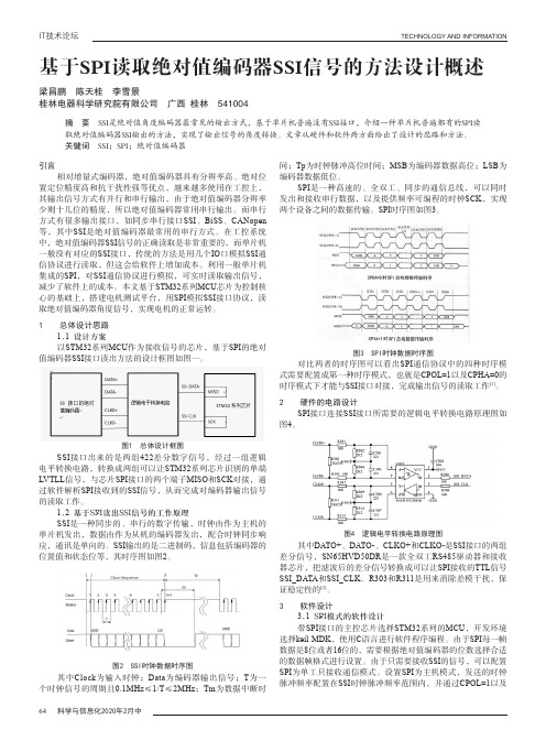
基于SPI读取绝对值编码器SSI信号的方法设计概述

基于SPI读取绝对值编码器SSI信号的方法设计概述作者:梁昌鹏陈天桂李雪景来源:《科学与信息化》2020年第05期摘要 SSI是绝对值角度编码器最常见的输出方式,基于单片机普遍没有SSI接口,介绍一种单片机普遍都有的SPI读取绝对值编码器SSI输出的方法,实现了输出信号的角度转换。
文章从硬件和软件两方面给出了设计的思路和方法。
关键词 SSI;SPI;绝对值编码器引言相对增量式编码器,绝对值编码器具有分辨率高、绝对位置定位精度高和抗干扰性强等优点,越来越多使用在工控上,其输出信号方式有并行和串行输出,由于绝对值编码器分辨率少则十几位的精度,所以绝对值编码器常用串行输出。
而串行方式有很多输出接口,如同步串行接口SSI、BiSS、CANopen等,其中SSI是绝对值编码器最常用的串行方式。
在工控系统中,绝对值编码器SSI信号的正确读取是非常重要的,而单片机一般没有对应的SSI接口,传统的方法是用几个IO口模拟SSI通信协议进行读取,但这会给软件上增加成本。
利用一般单片机集成的SPI,对SSI通信协议进行模拟,可实时读取输出信号,减少了软件上的成本。
本文基于STM32系列MCU芯片为控制核心的基础上,搭建电机测试平台,用SPI模拟SSI接口协议,读取绝对值编码器角度信号,实现电机的正常运转。
1 总体设计思路1.1 设计方案以STM32系列MCU作为接收信号的芯片,基于SPI的绝对值编码器SSI接口读出方法的设计框图如图一。
SSI接口出来的是两组422差分数字信号,经过一组逻辑电平转换电路,转换成两组可以让STM32系列芯片识别的单端LVTLL信号,与芯片SPI接口的两个端子MISO和SCK对接,通过软件解析SPI接收到的SSI信号,从而完成对编码器输出信号的读取工作。
1.2 基于SPI读出SSI信号的工作原理SSI是一种同步的、串行的数字传输,时钟由作为主机的单片机发出,数据由作为从机的编码器发出,配合时钟同步响应,通讯是单向的。
SSI通信协议
SSI通信协议协议名称:SSI通信协议一、引言SSI通信协议是一种用于数据传输和通信的标准协议。
本协议旨在确保数据的可靠性、完整性和安全性,以满足任务名称中所描述的内容需求。
本协议适用于各种通信设备和系统,包括但不限于传感器、控制器、数据采集器等。
二、术语定义在本协议中,以下术语定义适用于全文:1. SSI:同步串行接口(Synchronous Serial Interface)的缩写,指一种同步传输数据的接口标准。
2. 主设备:指发起数据传输请求的设备。
3. 从设备:指接收主设备传输请求并响应的设备。
4. 数据帧:指数据传输的基本单位,包括起始位、数据位、校验位和停止位。
三、通信流程1. 连接建立1.1 主设备发送连接请求到从设备。
1.2 从设备接收连接请求并返回确认信号。
1.3 主设备接收确认信号,连接建立成功。
2. 数据传输2.1 主设备发送数据请求到从设备。
2.2 从设备接收数据请求并准备数据。
2.3 从设备将数据按照数据帧格式发送给主设备。
2.4 主设备接收数据帧并进行校验。
2.5 主设备发送确认信号给从设备。
2.6 从设备接收确认信号,数据传输成功。
3. 连接关闭3.1 主设备发送关闭连接请求到从设备。
3.2 从设备接收关闭连接请求并返回确认信号。
3.3 主设备接收确认信号,连接关闭成功。
四、数据帧格式数据帧由以下部分组成:1. 起始位:用于标识数据帧的开始。
2. 数据位:包含要传输的数据。
3. 校验位:用于检测数据传输过程中的错误。
4. 停止位:用于标识数据帧的结束。
五、错误处理在数据传输过程中,可能会出现以下错误情况:1. 数据丢失:如果主设备在一定时间内没有接收到从设备的响应,则认为数据丢失,主设备将重新发送数据请求。
2. 数据错误:如果主设备接收到的数据帧校验位与实际数据不匹配,则认为数据错误,主设备将发送错误信号给从设备,并重新发送数据请求。
3. 连接超时:如果主设备在一定时间内没有收到从设备的确认信号,则认为连接超时,主设备将重新发送连接请求。
SSI功能的综合数据采集

USB总线MINI型250Ksps采集速度16位32通道AD 4通道12位DA输出8通道数字入/8通道数字出4路脉冲采集RBH8268使用说明书V1.0 RBH8268-21:SSI接口型北京瑞博华控制技术有限公司二0一0年二月250Ksps采集速度16位32通道AD4通道12位DA输出8通道数字入/8通道数字出4路脉冲采集RBH8268-21SSI接口型使用说明书V1.0一、性能特点:本板采用USB2.0接口的MINI型综合采集控制卡。
具有1路SSI接口功能。
本采集器一个重要特点是体积小巧,只有A4纸张的1/4大小;直接用USB总线供电,不需要外部供电;与Frecord软件无缝配合,特别适合于放置在笔记本电脑的包内,方便携带,是现场信息采集的好帮手。
本板通过采用高速高精度AD芯片、高精度的放大器、高密度FPGA逻辑芯片、精细地布线以及优良的制版工艺,实现了高速、高精度实时数据采集,具有以下性能特点:1、32通道模拟量高速采集。
可以设置1-32通道采集,起始通道号可以自由设定。
2、AD幅值采集高精度:16位采集精度,长时间采集时,误差跳码为±2LSB,相对精度优于0.001%,直流电压波动小于0.1毫伏。
3、AD高速连续采集:采集方式为连续采集,可以连续不断地采集,采集结果直接存放到计算机的内存,或存放到硬盘,在采集的数据量仅仅决定于用户的硬盘。
4、AD采集定时高精度:本板直接在CPLD控制下工作,由硬件时钟直接控制采集与传输,采集精度与晶振精度相同,缺省定时精度误差小于50PPM。
对于有特殊要求的用户,可以通过更换晶振的方式,达到0.1PPM精度,甚至更高精度。
5、软件校准:将校准信息存储在板卡上,用户不用打开仪器设备就可以进行校准,使用方便,一般情况下不需要用户进行任何校准。
6、丰富的备用扩展资源:板上CPLD资源非常丰富,可以为用户的特殊需求进行定制,如旋转编码器接口、脉冲周期测量接口、PWM输出接口、外同步接口、触发记录接口、开关量控制接口等(定制)。
SSI接口
1HXZLHGHU 6WUD H ' 1 UQEHUJ3KRQH M47User Manual20M 047-00 E 2SSIController M-ModuleM47 - SSI Controller M47 - SSI ControllerThe M47 is a Serial Synchronous Interface M-Module allowing connection of up tofour sensors to optically isolated SSI outputs. SS interfaces are very commonly usedfor sensors such as rotary encoders. Connection to the senors is by two signals only- a transmit clock and a receive data signal. The physical interface conforms to thedifferential RS422A standard. Data is transmitted to the M47 in gray or binary code.The user can handle sensors very easily with the help of the M47 SS interface. Allcommunication and signal decoding is done in an F PGA. After initialization, theuser has a RAM-like interface. He can continuously read the present values frommemory, without any interaction.It is also possible for the M-Module to generate an interrupt on a new datatransmission.Technical DataSSI Interface:•4-channel Serial Synchronous Interface (SSI)•optical isolation for each channel•RS422A interfaceData Transmission:•programmable baud rates•programmable word length (1..32)Memory:•16-byte dual-ported RAMInterfaces:• 4 RS422 ports, optically isolated•supply voltage for external sensors etc.: 5V (±10%) @ 200mA max. for all 4channelsMiscellaneous:•automatic communication•RAM-like double buffer user interface•Gray and binary decoding•sensor connection detection•interrupt triggering on a new data transmissionPeripheral Connections:•via front panel on a shielded 25-pin D-Sub receptacle connector•via carrier boardM-Module Characteristics:•A08, D08, INTA, IDENTElectrical Specifications:•isolation voltage: 500V DC•supply voltage/power consumption:+5V (4.85V..5.25V) @ 500mA typ.•MTBF: 33,000h @ 50°CMechanical Specifications:•dimensions: conforming to M-Module Standard•weight: 90gEnvironmental Specifications:•temperature range (operation): 0..+60°C(industrial temperature range on request)•temperature range (storage): -40..+85°C•relative humidity range (operation): max. 95% non-condensing•relative humidity range (storage): max. 95% non-condensing•altitude: -300m to + 3,000m•shock: 15g/0.33ms, 6g/6ms•vibration: 1g/5..2,000HzSafety:•PCB manufactured with a flammability rating of 94V-0 by UL recognized manu-facturersEMC:•tested according to IEC1000-4-2 (ESD) and IEC1000-4-4 (burst) with regard to CE conformitySoftware Support:•MEN Driver Interface System (MDIS)Block DiagramBlock Diagram16 Bytes Dual-PortedRAM (Alternating Buffer)Opto-couplerRS422Opto-coupler RS422Data ClockDCDCBaud Rate GeneratorTime Control M-Module InterfaceM-Module ID EEPROMControlD0..D7A1..A7Serial to ParallelGray to BinaryOrdering InformationOrdering InformationStandard HardwareAccessoriesStandard SoftwareUser Manuals04M047-00M47 hardware05M000-00M-Module cable, 2m, with 25-pin D-Sub plug/housing to pig tail 05M000-1725 mounting screw sets to fix M-Modules on carrier boards 13M047-06low-level driver sources (MDIS 4), incl. M47 MDIS user manual For use of MDIS you also need MEN ’s basic operating-system specific software package:13M000-0613M000-0713M000-08MDIS 4 for WindowsNT MDIS 4 for VxWorks MDIS 4 for OS-9All three include a comprehensive MDIS user guide.20M047-00M47 user manualAbout the ManualThis user manual describes the hardware functions of the M-Module, connection of peripheral devices and integration into a system. It also provides additional information for special applications and configurations of the board.The manual does not include detailed information on individual components (data sheets etc.). A list of literature is given in the appendix.HistoryConventionsThis sign marks important notes or warnings concerning proper functionality of the product described in this manual. You should read them in any case.Folder and file names are printed in italics .Bold type is used for emphasis.Hyperlinks are printed in blue color .Hexadecimal numbers are preceded by "0x", which is the usual C-language convention, and are printed in a monospace type, e.g. 0x00FFFF .Signal names preceded by a slash ("/") indicate that this signal is either active low or that it becomes active at a falling edge.Signal directions in signal mnemonics tables generally refer to the corresponding board or component, "in" meaning "to the board or component", "out" meaning "coming from it".Vertical lines on the outer margin signal technical changes to the previous edition of the manual.Edition Description Technical Content Date of Issue E1First edition Manfred Schmitz April 4, 1995E2Second editionManfred SchmitzNovember 20, 1999!italics bold hyperlink 0xFF/IRQin/outMEN reserves the right to make changes without further notice to any products herein. MEN makes no warranty, representation or guarantee regarding the suitability of its products for any particular purpose, nor does MEN assume any liability arising out of the application or use of any product or circuit, and specifically disclaims any and all liability, including without limitation consequential or incidental damages. "Typical" parameters can and do vary in different applications. All operating parameters, including "Typicals" must be validated for each customer application by customer's technical experts.MEN does not convey any license under its patent rights nor the rights of others.MEN products are not designed, intended, or authorized for use as components in systems intended for surgical implant into the body, or other applications intended to support or sustain life, or for any other application in which the failure of the MEN product could create a situation where personal injury or death may occur. Should Buyer purchase or use MEN products for any such unintended or unauthorized application, Buyer shall indemnify and hold MEN and its officers, employees, subsidiaries, affiliates, and distributors harmless against all claims, costs, damages, and expenses, and reasonable attorney fees arising out of, directly or indirectly, any claim of personal injury or death associated with such unintended or unauthorized use, even if such claim alleges that MEN was negligent regarding the design or manufacture of the part.All brand or product names are trademarks or registered trademarks of their respective holders.Information in this document has been carefully checked and is believed to be accurate as of the date of publication; however, no responsibility is assumed for inaccuracies. MEN will not be liable for any consequential or incidental damages arising from reliance on the accuracy of this document. The information contained herein is subject to change without notice.Copyright © 1999 MEN Mikro Elektronik GmbH. All rights reserved.Contents Contents1Getting Started . . . . . . . . . . . . . . . . . . . . . . . . . . . . . . . . . . . . . . . . . . . . . . . . 101.1Installation Check List. . . . . . . . . . . . . . . . . . . . . . . . . . . . . . . . . . . . . 101.2Installing Driver Software. . . . . . . . . . . . . . . . . . . . . . . . . . . . . . . . . . 101.3Power Supply. . . . . . . . . . . . . . . . . . . . . . . . . . . . . . . . . . . . . . . . . . . . 102Connection of the M-Module. . . . . . . . . . . . . . . . . . . . . . . . . . . . . . . . . . . . . 112.1Peripheral Interfaces . . . . . . . . . . . . . . . . . . . . . . . . . . . . . . . . . . . . . . 112.2Host Interface . . . . . . . . . . . . . . . . . . . . . . . . . . . . . . . . . . . . . . . . . . . 133Address Organization. . . . . . . . . . . . . . . . . . . . . . . . . . . . . . . . . . . . . . . . . . . 144Functional Description. . . . . . . . . . . . . . . . . . . . . . . . . . . . . . . . . . . . . . . . . . 154.1SSI Transmission. . . . . . . . . . . . . . . . . . . . . . . . . . . . . . . . . . . . . . . . . 154.2Setting the Baud Rate and Bit Width. . . . . . . . . . . . . . . . . . . . . . . . . . 164.3Setting the Data Transmission Mode. . . . . . . . . . . . . . . . . . . . . . . . . . 164.4Detecting Sensors . . . . . . . . . . . . . . . . . . . . . . . . . . . . . . . . . . . . . . . . 174.5Reading Values from the Data RAM. . . . . . . . . . . . . . . . . . . . . . . . . . 174.6Interrupts . . . . . . . . . . . . . . . . . . . . . . . . . . . . . . . . . . . . . . . . . . . . . . . 184.7M-Module Identification and FLEXlogic . . . . . . . . . . . . . . . . . . . . . . 195Appendix . . . . . . . . . . . . . . . . . . . . . . . . . . . . . . . . . . . . . . . . . . . . . . . . . . . . . 205.1Literature. . . . . . . . . . . . . . . . . . . . . . . . . . . . . . . . . . . . . . . . . . . . . . . 205.2Board Revisions. . . . . . . . . . . . . . . . . . . . . . . . . . . . . . . . . . . . . . . . . . 205.3Configuration Plan. . . . . . . . . . . . . . . . . . . . . . . . . . . . . . . . . . . . . . . . 20FiguresFigure 1:Serial Synchronous Data Transmission . . . . . . . . . . . . . . . . 15Figure 2:Sequence for Reading Values from the Data RAM . . . . . . . 17Figure 3:Configuration Plan of M47 Rev. 01 . . . . . . . . . . . . . . . . . . . 20 TablesTable 1:Pin Assignment of the female 25-Pin D-Sub Connector . . . 11Table 2:Female 24-Pin Connector . . . . . . . . . . . . . . . . . . . . . . . . . . . 12Table 3:Signal Correspondence between 24-Pin Module and 96-pinCarrier Board Connector. . . . . . . . . . . . . . . . . . . . . . . . . . . . 12Table 4:Signal Mnemonics. . . . . . . . . . . . . . . . . . . . . . . . . . . . . . . . . 12Table 5:Supported Pins of male 60-Pin Connector on Carrier Board 13Table 6:Address Map. . . . . . . . . . . . . . . . . . . . . . . . . . . . . . . . . . . . . 14Table 7:Table of Hardware Revisions . . . . . . . . . . . . . . . . . . . . . . . . 20Getting Started 1Getting StartedThis chapter will give some hints for first installation in a system as a "check list".1.1Installation Check ListYou can use the following "check list" to install the M-Module on a carrier board forthe first time and to test proper functioning of the board.The M-Module is completely trimmed on delivery. Perform the following procedure !without the M-Module installed!;Power-down the system.;Install the M-Module carrier board in your system without the M-Module.;Power-up the system.;Test the carrier board.;If O.K., power-down the system and remove the carrier board.;Install the M-Module in slot 0 of the carrier board.;Initially, do not change any jumpers or switches.;Insert the carrier board into the system again.;Power-up the system.;Load a suitable debugger.;Access the base address as set, reading word by word.;If a bus error is occurring now, the M-Module is not plugged properly.;Write the word 0x0000 to the base address plus 0x0080.;Write the word 0x0055 to the base address plus 0x0000.;You should be able to reread these values.1.2Installing Driver SoftwareFor a detailed description on how to install and use driver software please refer tothe M-Module’s software user manual. F or available software please refer toChapter Ordering Information on page 6 or MEN’s website: http://www.men.de.1.3Power SupplyPower supply to the logic part is done via the carrier board. The necessary voltage is+5V. The isolated supply voltages (5V) are generated on the M-Module itself.External sensors can also be supplied by the isolated 5V. External powerconsumption should not exceed 1W.2Connection of the M-Module2.1Peripheral InterfacesThere are two possibilities for connecting peripherals:•connection via 25-pin D-Sub connector or •connection via the carrier board.When a carrier board with a 96-pin DIN 41612 PCB connection is used for peripheral signals (for example a 6U VMEbus board), these are fed to the M-Module through the 24-pin receptacle connector. You can connect up to four 21-pin connectors to the 96-pin connector (cf. carrier board manual). When these connectors are used, for each M-Module three pins of the DIN 41612 PCB connector cannot be used. The pin numbers for the 96-pin connector shown below are valid for M-Module slot number 3. If other M-Module slots (2, 1 or 0) are used,the value 8, 16 or 24 must be added as appropriate.Note:The four channels are marked through different colors in the tables.Table 1:Pin Assignment of the 25-Pin D-Sub Receptacle ConnectorConnector types:•according to DIN41652/MIL-C-24308, with thread bolt UNC 4-40•mating connector:25-pin D-Sub plug according to DIN41652/MIL-C-24308, available for ribbon cable (insulation piercing connection), hand-soldering connection or crimp connection1ACLK+14ADAT A+2ACLK-15ADATA-3VCC_DC 16GND_DC 4BCLK+17BDAT A+5BCLK-18BDATA-6VCC_DC 19GND_DC 7CCLK+20CDATA+8CCLK-21CDA TA-9VCC_DC 22GND_DC 10DCLK+23DDATA+11DCLK-24DDA TA-12VCC_DC 25GND_DC13GND_DC1141325Table 2:24-Pin Receptacle ConnectorConnector types:•two 12-pin receptacles, high-precision, 2.54mm pitch, for square pins ∅0.635mm gold, 6.9mm height•mating connector:two 12-pin plugs, 2.54mm pitch, square pins ∅0.635mm gold Table 3:Signal Correspondence between 24-Pin Module and 96-pin Carrier Board ConnectorTable 4:Signal Mnemonics23GND_DC 24GND_DC 21GND_DC 22GND_DC 19GND_DC 20GND_DC 17GND_DC 18GND_DC 15DDA T A+16DDA TA-13DCLK+14DCLK-11CDA T A+12CDA TA-9CCLK+10CCLK-7BDA T A+8BDA TA-5BCLK+6BCLK-3ADA T A+4ADA TA-1ACLK+2ACLK-ABC1ACLK+ACLK-ADA TA+2ADA TA-BCLK+BCLK-3BDA TA+BDA TA-CCLK+4CCLK-CDA T A+CDA T A-5DCLK+DCLK-DDA TA+6DDA TA-GND_DC GND_DC7GND_DC GND_DC GND_DC 8GND_DC GND_DC GND_DCSignalDirection Functionx CLK+/x CLK-out differential pairs of clock output lines for channels A..Dx DA TA+/x DATA-in differential pairs of data input lines for channels A..DGND_DC -digital ground reference for channels A..D VCC_DC-+5V supply voltage for channels A..D (for external sensors). The wattage must not exceed 1W for all channels!2312241A B C2.2Host InterfaceThe M-Module supports the following signals of a 60-pin carrier board interface plug connector:Note:Only two rows - A and B - of the 60-pin connector are mounted on the M47!Table 5:Supported Pins of 60-Pin Plug Connector on Carrier BoardConnector types:•three 20-pin receptacles, high-precision, 2.54mm pitch, for square pins ∅0.635mm gold, 6.9mm height•mating connector:three 20-pin plugs, 2.54mm pitch, square pins ∅0.635mm goldAB C 1/CS GND -2A01+5V -3A02--4A03--5A04--6A05--7A06--8A07--9-D00-10-D01-11-D02-12-D03-13-D04-14-D05-15-D06-16-D07-17---18/DTACK /WRITE -19-/IRQ-20/RESET SYSCLK-120A B CAddress Organization3Address OrganizationWhen using the driver software supplied, you do not need to be familiar with the hardware of the M-Module in detail. However, familiarity with the address organization of the board is essential if you wish to write your own software for the M-Module or do low-level development.The 256-byte I/O area of the M-Module is hardware-mapped. The address at which individual functions can be addressed from the carrier board is computed from the base address of the M-Module plus the address in the following table.Table 6:Address MapAddress D15..D8D7..D0Read Access Write Access 0x00-data d31..d24C h a n n e l A buffer RAM #10x02-data d23..d16buffer RAM #10x04-data d15..d8buffer RAM #10x06-data d7..d0buffer RAM #10x08-data d31..d24C h a n n e l B buffer RAM #10x0A -data d23..d16buffer RAM #10x0C -data d15..d8buffer RAM #10x0E -data d7..d0buffer RAM #10x10-data d31..d24C h a n n e l C buffer RAM #10x12-data d23..d16buffer RAM #10x14-data d15..d8buffer RAM #10x16-data d7..d0buffer RAM #10x18-data d31..d24C h a n n e l Dbuffer RAM #10x1A -data d23..d16buffer RAM #10x1C -data d15..d8buffer RAM #10x1E -data d7..d0buffer RAM #10x21, 0x23..0x3E -reserved buffer RAM #20x80-Control Register0x84-Mode/PLD Revision Register 0xA0-Status Registerreserved0xFE-FLEXlogic/M-Module Identification Register and Interrupt Enable Register4Functional Description4.1SSI TransmissionSerial synchronous interfaces consist of a transmit clock line and a receive data line.When there is no transmission, the clock and data lines are "high". The M-Module transmits a clock sequence to the encoder to obtain the current position value. On the first falling edge of the clock the value is latched at the sensor output. On each of the subsequent rising edges, one bit of data is transmitted to the M-Module. After transmission of a complete data word, the clock line will remain "high" until new data is available at the sensor output.Figure 1:Serial Synchronous Data TransmissionData transmission is completely independent, without any interaction of the CPU. If incoming data is Gray encoded, it will be automatically converted to binary code.All four channels are loaded simultaneously.The bit sequence is written directly to the buffer RAM at the correct bit position. A double buffer mechanism makes sure that a complete data word is read. The CPU always reads a complete data word from one half of the buffer. In the meantime the transmission process uses the other half of the RAM. When the CPU is reading a data word, automatic switching between the two buffer halves is suspended until the complete word has been read. The CPU can easily read current information from the sensor without software overhead.Clock DataTransmission StartBreakTransmission Start4.2Setting the Baud Rate and Bit WidthAn 8-bit control register defines the baud rate and the number of bits in a data word (bit width). The value is equal for all four channels. Setting the number of bits in a data word to zero stops the transmission. The maximum data word length is 32. In applications with different kinds of sensors connected to a single M-Module it might be possible to select the maximum number of bits (32) and adapt the incoming bits by software.The baud rate must be as slow as the slowest connected sensor.Control Register (0x80) (read/write)15..87..2 1..0-BW BR BW:number of bits in a data word (bit width), 1..320 0 0 0 0 0 = stop transmission0 0 0 0 0 1 = 1 bit in data word..1 0 0 0 0 0 = 32 bits in data wordOther values are not permitted!BR:0 0 = 500 kbaud0 1 = 250 kbaud1 0 = 125 kbaud1 1 = 62.5 kbaud4.3Setting the Data Transmission ModeThe M47 supports both Gray and binary encoded data. You can set the mode in the Mode/PLD Revision Register:Mode/PLD Revision Register (0x84) (read/write)15..87 6..4 3..0-MODE-PLD_Rev MODE:changes between Gray and binary mode.The setting takes effect on all channels.0 = Gray encoder (default)1 = binary encoderPLD_Rev: PLD revision number (read-only!)4.4Detecting SensorsThe user can read a 4-bit status register to detect if there is a sensor connected to a channel or not. If the channel bit is '1', the sensor is transferring data to the corresponding channel. The only possibility to clear a bit is to write '0'. After clearing the bits, you must wait for at least two transmission cycles. Then you can read the register again to detect whether a sensor is connected.Status Register (0xA0) (read)15..87..43210-RES TD TC TB TARES:reserved (undefined on reading)TD:0 = clear this bit1 = channel D is transferring dataTC:0 = clear this bit1 = channel C is transferring dataTB:0 = clear this bit1 = channel B is transferring dataTA:0 = clear this bit1 = channel A is transferring data4.5Reading Values from the Data RAMAfter setting the control register, you should clear the complete data RAM and -after at least one transmission cycle - you must perform a dummy read. Then you can read the current values without any interaction.Because of the buffer mechanism all four bytes of a channel should be read, even if the data word is smaller. When reading a value, you must stick to the following order to get valid data:Figure 2:Sequence for Reading Values from the Data RAMRead Data Byted31..d24Read Data Byted23..d16Read Data Byted15..d8Read Data Byted7..d04.6InterruptsFor special requirements the M47 M-Module can trigger an interrupt to the carrier board. Interrupts to the M-Module are in accordance with type a) of the M-Module Specification (see Chapter 5.1 Literature on page 20), i.e., the interrupt request is reset by software, but the M47 M-Module itself is not able to supply a vector during the interrupt-acknowledge cycle.The interrupt cause is receiving a new data word. It is not possible to mask this interrupt (this should be done on the carrier board). The INT bit in the Interrupt Enable Register can be read and written. Therefore, also if the interrupt function is not used, the user can make a software acknowledge by setting this bit. When the bit is cleared a new value is available.Interrupt Enable Register (0xFE ) (read/write)INT:0 = new data available1 = no new data available15..87 6..43210-INT-FLEX TMSSELFLEX/ID CLKFLEX/ID DA TA4.7M-Module Identification and FLEXlogicThe M47 M-Module is supplied with an identification EEPROM in accordance with the M-Module specification.FLEXlogic/M-Module Identification (0xFE ) (read/write)Both the FLEXlogic and the M-Module identification EEPROM can be accessed at address 0xFE . The selection is made through bit SEL:0 = FLEXlogic access1 = M-Module ID EEPROM access15..876..4321-INT-FLEXTMSSELFLEX CLK FLEX DA TA---ID CLKID DA TAAppendix5Appendix5.1Literature•M-Module Standard:ANSI/VITA 12-1996, M-Module Specification;VMEbus International Trade Association 7825 E. Gelding Dr., Ste. 104, Scottsdale, AZ 85260WWW: 5.2Board RevisionsTable 7:Table of Hardware RevisionsNote:As of hardware revision 01.04 the M47 M-Module also supports binaryencoders in addition to Gray encoders.5.3Configuration PlanFigure 3:Configuration Plan of M47 Rev. 01RevisionCommentRestrictions00.xx first revision released M-Module identification not implemented yet 01.xxsecond revision releasednone known1HXZLHGHU 6WUD H ' 1 UQEHUJ Non-Disclosure Agreementfor Circuit Diagrams provided by MEN Mikro Elektronik GmbHbetweenMEN Mikro Elektronik GmbHWiesentalstr. 40D-90419 Nürnberg(”MEN ”)and________________________________________________________________________________(”Recipient ”)We confirm the following Agreement:The following Agreement is valid as of the date of MEN’s signature.MEN RecipientDate:______________________Date:______________________Name:______________________Name:______________________Function:______________________Function:______________________Signature:Signature:________________________________________________________________________Y ou can request the circuit diagrams for the current revision of the product described in this manual by completely filling out and signing the following non-disclosure agreement.Please send the agreement to MEN by mail. We will send you the circuit diagrams along with a copy of the completely signed agreement by return mail.MEN reserves the right to refuse sending of confidential information for any reason that MEN may consider substantial.1SubjectThe subject of this Agreement is to protect all information contained in the circuit diagrams of thefollowing product:Article Number:__________________ [filled out by recipient]MEN provides the recipient with the circuit diagrams requested through this Agreement only forinformation.2Responsibilities of MENInformation in the circuit diagrams has been carefully checked and is believed to be accurate asof the date of release; however, no responsibility is assumed for inaccuracies. MEN will not be lia-ble for any consequential or incidental damages arising from reliance on the accuracy of the cir-cuit diagrams. The information contained therein is subject to change without notice.3Responsibilities of RecipientThe recipient, obtaining confidential information from MEN because of this Agreement, is obligedto protect this information.The recipient will not pass on the circuit diagrams or parts thereof to third parties, neither to indi-viduals nor to companies or other organizations, without the written permission by MEN. The cir-cuit diagrams may only be passed to employees who need to know their content. The recipientprotects the confidential information obtained through the circuit diagrams in the same way as heprotects his own confidential information of the same kind.4Violation of AgreementThe recipient is liable for any damage arising from violation of one or several sections of thisAgreement. MEN has a right to claim damages amounting to the damage caused, at least toDM100,000.5Other AgreementsMEN reserves the right to pass on its circuit diagrams to other business relations to the extentpermitted by the Agreement.Neither MEN nor the recipient acquire licenses for the right of intellectual possession of the otherparty because of this Agreement.This Agreement does not result in any obligation of the parties to purchase services or productsfrom the other party.6Validity of AgreementThe period after which MEN agrees not to assert claims against the recipient with respect to theconfidential information disclosed under this Agreement shall be _______ months [filled out byMEN]. (Not less than twenty-four (24) nor more than sixty (60) months.)7GeneralIf any provision of this Agreement is held to be invalid, such decision shall not affect the validity ofthe remaining provisions and such provision shall be reformed to and only to the extent neces-sary to make it effective and legal.This Agreement is only effective if signed by both parties.Amendments to this Agreement can be adopted only in writing. There are no supplementary oralagreements.This Agreement shall be governed by German Law.The court of jurisdiction shall be Nuremberg.1HXZLHGHU 6WUD H' 1 UQEHUJ1HXZLHGHU 6WUD H ' 1 UQEHUJ Who you are...Name __________________________Phone No.__________________________Company __________________________Fax No.__________________________Department __________________________E-mail __________________________What we can do for you...Product Support Manual FeedbackProduct Article No. Revision ____________________ __ . __ __ . __ __Manual Article No.Edition __________________E ___If the product is a mezzanine module:Useful or awful?very useful totally awful Carrier Article No.Revision ____________________ __ . __ __ . __ __Operating system OS-9 VxWorks WindowsNT other:___________________________________UsageI read the manual and decided to buy the related product.I read the manual when I got the product. I referred to the manual only when I hadinstallation problems.Your problems/comments...Fax ReplyUse our online forms at http://www.men.de •Technical Support •User Manuals。
一种工控机高速采集SSI接口数据的方法靳红涛

收稿日期:2011-12-28一种工控机高速采集SSI 接口数据的方法靳红涛,赵勇进,张晓曦(中国兵器工业第二〇八研究所,北京102202)摘要:同步串行接口(SSI)具有速度快、连线简单、抗干扰能力强等优点,在工业控制等领域得到了越来越广泛的应用。
一般的工控机上不提供SSI 接口,市场上的SSI 接口扩展卡很少且价格昂贵。
介绍了SSI 并行接口模块SSI208P ,基于数字量输入/输出扩展卡和SSI208P ,给出了一种工控机高速采集多通道SSI 光电编码器数据的低成本实现方案,详细阐述了硬件和软件设计方法。
关键词:SSI ;光电编码器;工控机;数据采集Implementation of high speed SSI data acquisition by industrial control computerJIN Hong-tao ,ZHAO Yong-jin ,ZHANG Xiao-xi(No.208Research Institute of China Ordnance Industries,Beijing102202,C hina)Abstract:Synchronous Serial Interface (SSI)has such advantages as high transfer speed,simple connection,excellent noise proof feature and it is widely used in industrial control and other fields.However,SSI is not provided in most industrial control computers and the extended SSI cards are expensive and hard to find on the mark.Based on the SSI module of SSI208P and digital input/output card,a low cost implementation of multi SSI photoelectric encoder high speed data acquisition by industrial control computer is introduced.Hardware and software are given in detail.Keywords:SSI ;photoelectric encoder ;industrial control computer ;data acquisitionSSI (Synchronous Serial Interface)即同步串行接口,具有传输速度快、连线简单、抗干扰能力强等优点,在光电编码器等各种传感器上得到了广泛的应用[1,2]。
SSI通信协议

SSI通信协议协议名称:SSI通信协议一、引言SSI通信协议旨在规范数据传输过程中的通信规则和数据格式,确保通信的稳定性和可靠性。
本协议适用于任何需要使用SSI通信协议进行数据传输的系统或设备。
二、定义1. SSI:同步串行接口(Synchronous Serial Interface)是一种数据传输接口,用于在两个设备之间进行同步数据传输。
2. 主设备:指发起数据传输请求并控制数据传输过程的设备。
3. 从设备:指接收主设备传输请求并响应数据传输的设备。
三、通信规则1. 数据帧:数据帧是通信过程中的基本单位,包含起始位、数据位、校验位和停止位。
2. 通信速率:通信速率应根据系统需求进行设定,并在主设备和从设备之间保持一致。
3. 同步信号:主设备通过发送同步信号来指示从设备开始接收数据。
4. 响应确认:从设备在接收到数据后应发送确认信号给主设备,表示数据接收成功。
5. 错误处理:在数据传输过程中,如发生错误,主设备和从设备应根据错误类型进行相应的处理和通知。
四、数据格式1. 数据类型:数据可以是数字、字符或其他格式,根据实际应用需求进行定义。
2. 数据长度:数据长度应根据实际应用需求进行定义,并在主设备和从设备之间保持一致。
3. 数据编码:数据编码方式应根据实际应用需求进行选择,常用的编码方式包括ASCII码、二进制码等。
4. 数据传输顺序:数据传输顺序应根据实际应用需求进行定义,可以是从高位到低位或从低位到高位。
五、数据传输流程1. 主设备发送同步信号给从设备,指示数据传输开始。
2. 主设备发送数据帧给从设备。
3. 从设备接收数据帧,并发送确认信号给主设备。
4. 主设备接收确认信号,并根据需要继续发送数据帧。
5. 数据传输完成后,主设备发送停止信号给从设备,指示数据传输结束。
六、错误处理1. 数据校验错误:如果接收到的数据帧校验错误,从设备应发送错误信号给主设备,并重新请求数据传输。
2. 超时错误:如果数据传输过程中超时,主设备应发送超时错误信号给从设备,并重新请求数据传输。
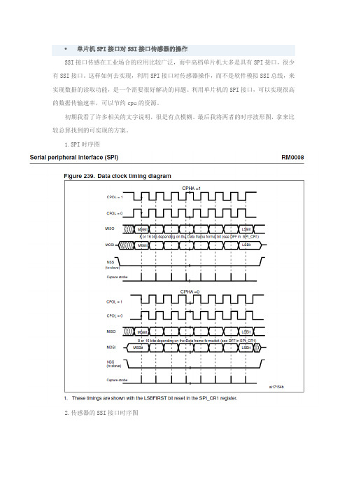
单片机SPI接口对SSI接口传感器的操作
单片机SPI接口对SSI接口传感器的操作
SSI接口传感在工业场合的应用比较广泛,而中高档单片机大多是具有SPI接口,很少有SSI接口。
这样如何去实现,利用SPI接口对传感器操作,而不是软件模拟SSI总线,来实现数据的读取功能,是一个需要很好解决的问题。
利用单片机的SPI接口,可以实现很高的数据传输速率,可以节约cpu的资源。
初期我看了许多相关的文字说明,很是有点模糊。
最后我将两者的时序波形图,拿来比较总算找到的可实现的方案。
1.SPI时序图
2.传感器的SSI接口时序图
3.从图中分析可以得出,将单片机的SPI接口,配置成第三种时序模式,即可实现数据的读取。
值得注意的问题是,此种模式下读到的第一位数据是无效的,在软件上需要对读到的数据进行一些简单的处理。
4.传感器的信号是R485标准的差分信号,因此还需要差分转换器实现信号的转换例如(3.3V ,sn75176;5V,sn75hvdl10)。
基于SSI协议的高速运动参数测量接口设计

基于SSI协议的高速运动参数测量接口设计张凯;吴爱国;张第【期刊名称】《自动化与仪表》【年(卷),期】2012(27)7【摘要】Through adopting FPGA and other auxiliary chip as the hardware platform,and programming FPGA though the use of Verilog HDL,the FPGA internal achieved a high speed measuring interface within SSI communications protocol timing control and signal conversion,M velocity method and T velocity method,and dual-port RAM as data storage and in the transit core. Finally,tests show that this interface characterized in more stable use,fast,efficient,and flexibility.%采用FPGA和其他辅助芯片作为硬件平台,并通过使用HDL语言对FPGA编程,在FPGA内部实现了带有SSI通信协议的时序控制与信号转换和M法、T法两种速度算法的高速运动参数测量接口,并且加入双口RAM作为数据存储于中转核心.最后经过测试,本接口具有快速高技、稳定使用、灵活性强等优点.【总页数】4页(P54-57)【作者】张凯;吴爱国;张第【作者单位】天津大学电气与自动化工程学院,天津 300072;天津大学电气与自动化工程学院,天津 300072;天津大学电气与自动化工程学院,天津 300072【正文语种】中文【中图分类】TP311【相关文献】1.基于JESD204B协议的数据采集接口设计与实现 [J], 王红亮;曹京胜2.基于MODBUS协议的单片机与触摸屏通讯接口设计 [J], 欧阳崇伟;杨秋萍;李疆3.基于JESD204B协议的ADC高速串行接口设计与实现 [J], 梁晨4.基于FPGA的RS-232通信协议接口设计 [J], 燕伯峰;董永乐;余佳;刘宇鹏;黄欣;石浩渊5.基于规约协议的水泥散装计量系统的接口设计与应用 [J], 王亚峰因版权原因,仅展示原文概要,查看原文内容请购买。
数据采集的常用方法

数据采集的常用方法一、概述数据采集是指从网络或其他数据源中收集数据的过程。
在当今信息时代,数据采集已成为各行各业必不可少的工作。
本文将介绍数据采集的常用方法。
二、常用方法1. 网络爬虫网络爬虫是指通过程序自动访问互联网上的网页,并将网页上的信息抓取下来的一种技术。
网络爬虫可以快速地获取大量数据,但是需要注意合法性和道德性。
2. API接口API(Application Programming Interface)接口是指应用程序开发者提供给其他开发者使用的一组程序接口。
通过API接口,可以直接获取到所需的数据,而且获取到的数据通常都是经过处理和筛选后的高质量数据。
3. 数据库查询数据库查询是指通过SQL语句查询数据库中所需的数据。
数据库查询可以根据需要精确地获取所需的数据,并且可以对查询结果进行加工和处理。
4. 人工输入人工输入是指手动输入或复制粘贴等方式将所需数据录入电脑中。
虽然这种方式比较繁琐,但对于一些无法通过自动化手段获取的数据,人工输入仍然是必要的手段。
三、具体操作步骤1. 网络爬虫(1)确定目标网站和需要采集的信息。
(2)编写爬虫程序,通过Python等编程语言实现。
(3)运行爬虫程序,获取数据。
2. API接口(1)查找合适的API接口,可以通过Google、百度等搜索引擎进行查找。
(2)根据API文档,了解API的使用方法和参数要求。
(3)编写程序调用API接口获取数据。
3. 数据库查询(1)连接数据库,可以使用MySQL、Oracle等数据库管理系统。
(2)编写SQL语句查询所需数据。
(3)将查询结果导出为Excel、CSV等格式文件。
4. 人工输入根据需要将所需数据手动输入或复制粘贴到电脑中,并进行必要的处理和整理。
四、注意事项1. 合法性问题:在进行数据采集时,需要遵守相关法律法规和道德规范。
不得采集涉及个人隐私、商业秘密等敏感信息,并且需要注意版权问题。
2. 数据质量问题:在进行数据采集时,需要对所采集到的数据进行筛选和加工处理,确保获取到的是高质量的数据。
基于spi读取绝对值编码器ssi信号的方法设计概述
TECHNOLOGY AND INFORMATIONIT技术论坛64 科学与信息化2020年2月中基于SPI读取绝对值编码器SSI信号的方法设计概述梁昌鹏 陈天桂 李雪景桂林电器科学研究院有限公司 广西 桂林 541004摘 要 SSI是绝对值角度编码器最常见的输出方式,基于单片机普遍没有SSI接口,介绍一种单片机普遍都有的SPI读取绝对值编码器SSI输出的方法,实现了输出信号的角度转换。
文章从硬件和软件两方面给出了设计的思路和方法。
关键词 SSI;SPI;绝对值编码器引言相对增量式编码器,绝对值编码器具有分辨率高、绝对位置定位精度高和抗干扰性强等优点,越来越多使用在工控上,其输出信号方式有并行和串行输出,由于绝对值编码器分辨率少则十几位的精度,所以绝对值编码器常用串行输出。
而串行方式有很多输出接口,如同步串行接口SSI 、BiSS 、CANopen 等,其中SSI 是绝对值编码器最常用的串行方式。
在工控系统中,绝对值编码器SSI 信号的正确读取是非常重要的,而单片机一般没有对应的SSI 接口,传统的方法是用几个IO 口模拟SSI 通信协议进行读取,但这会给软件上增加成本。
利用一般单片机集成的SPI ,对SSI 通信协议进行模拟,可实时读取输出信号,减少了软件上的成本。
本文基于STM32系列MCU 芯片为控制核心的基础上,搭建电机测试平台,用SPI 模拟SSI 接口协议,读取绝对值编码器角度信号,实现电机的正常运转。
1 总体设计思路1.1 设计方案以STM32系列MCU 作为接收信号的芯片,基于SPI 的绝对值编码器SSI接口读出方法的设计框图如图一。
图1 总体设计框图SSI 接口出来的是两组422差分数字信号,经过一组逻辑电平转换电路,转换成两组可以让STM32系列芯片识别的单端LVTLL 信号,与芯片SPI 接口的两个端子MISO 和SCK 对接,通过软件解析SPI 接收到的SSI 信号,从而完成对编码器输出信号的读取工作。
MTS传感器配置SSI接口

MTS传感器配置SSI接口
佚名
【期刊名称】《酒.饮料技术装备》
【年(卷),期】2015(000)001
【摘要】近日,传感器供应商MTS系统公司宣布为Temposonics GBS稳健型磁致伸缩传感器引入了SSI接口。
实现了新的常用输出模式,最高分辨率达到5μin。
编程软件便于用户设置和调整同步或异步测嚣模憬、测量方向、代码及数据长度等参数。
这款杆式传感器不仅能够使用手动编程单元或借助计算机通过USB端口进
行编程,而且还可以通过蓝牙进行无线配置,因而便于启动和维护。
该传感器能够承受一定的压力,紧凑型电子外壳为扁平状,便于安装在受限空间内。
【总页数】1页(P41-41)
【正文语种】中文
【中图分类】TP212.13
【相关文献】
1.基于SSI接口的线位移传感器高速并行数据采集设计 [J], 梁军;王移川
2.ATmega16微控器的通用IO口与SSI协议传感器接口连接的实现 [J], 韩巍;张
立新;李大志
3.基于FPGA的SSI接口传感器通信系统 [J], 郭耀华;姚明林;张银蒲
4.光栅传感器测量系统前通道配置与接口设计 [J], 陈白宁;王生力
5.Classification of Single Traveling Wave Solutions to the Generalized Kadomtsev-Petviashvili Equation without Dissipation Terms in
<i>p</i>= 2 [J], Xinghua Du;Hua Xin
因版权原因,仅展示原文概要,查看原文内容请购买。
- 1、下载文档前请自行甄别文档内容的完整性,平台不提供额外的编辑、内容补充、找答案等附加服务。
- 2、"仅部分预览"的文档,不可在线预览部分如存在完整性等问题,可反馈申请退款(可完整预览的文档不适用该条件!)。
- 3、如文档侵犯您的权益,请联系客服反馈,我们会尽快为您处理(人工客服工作时间:9:00-18:30)。
如何进行SSI接口的数据采集?(Part I)
对于SSI接口的传感器可以采用并行和串行两种采集方法,分别对应
SSI208P和SSI-UART两种产品。
1、SSI接口转并口模块
SSI208P,主要应用于同步串行接口(SSI)光电编码器高速数据采集系统的板级开发。
SSI208P模块将同步串行接口数据转换成并行接口数据,内部集成了SSI 同步时钟发生器、脉冲计数器、数据串并转换、接口控制逻辑、输出控制以及收发驱动器(TTL-RS422电平转换)等功能单元,用户无须了解SSI数据格式,该模块自动将SSI数据转换成8位并行数据,简化了SSI编码器与DSP、单片机、PC104等控制器的接口。
(1)产品特性单3.3V供电,工作电流小于100mA;通信速率可配置,最高达2MHz;24脚双列直插封装,尺寸25.4*25.4*6(mm);8位数据总线,可接8~32位编码器;16位数据更新率大于100KHz;内部时钟,固定时序;内置422差分驱动。
(2)产品介绍该模块具有内部时钟,能自动将SSI数据转换成并行数据,对SSI接口数据的读取操作就类似于对A/D、D/A或存储器读取数据的操作一样方便。
SSI208P模块通信速率可配置为250KHz、500KHz、1MHz、2MHz,当通信速率配置为2MHz时,对于16位精度的编码器,系统数据更新率不低于100KHz。
此外,该模块对采集的数据长度(编码器精度)可以进行配置,最高可以采集32位数据,分4次输出,该模块可以满足高精度高速伺服控制系统的需求。
(3)外形尺寸25.4×25.4×6(mm).关于该模块的详细资料见SSIP208P说明书。
2、SSI接口转串口模块
SSI-UART模块可以将SSI同步串行数据转换成通用异步串行(UART,可配置为RS-232/RS485/RS422方式)数据,工控领域常用的PC机、工控机、DSP、单片机等控制系统上一般都配备有通用异步串行接口,使用SSI-UART模块可以方便地实现SSI编码器与这些控制系统的连接。
(1) 功能及参数
●SSI数据转换为RS-232通用异步串行数据;
●SSI时钟速率选择(125KHz、250KHz、500KHz、1MHz);
●支持格雷码和二进制码数据格式转换;
●支持编码器地址配置;
●可配置编码器供电电压5V或24V;
●供电方式:直流18-30V;
●电流:不大于60mA;
●工作温度:-40℃~-75℃;
外观尺寸:80mm×65mm×25mm。
(2) 通信协议
RS-232的通信速率115200bps,8位、1位停止位、无奇偶校验。
数据发送方式(问询方式或主动发送模式)选择。
1)主动发送时,发送周期为10ms,每帧数据7个字节:
数据字节号含义数据格式
数据帧头0xAA
地址信息0x00/0x01/0x02/0x03
数据高位0xXX
数据次高位 0xXX
数据次低位 0xXX
数据低位0xXX
校验位4个字节数据相加值的低八位
2)被动发送时,向模块发送地址信息,一个字节0x00/0x01/0x02/0x03(地址方法见SSI-UART说明书),模块向主控机返回一帧数据。
关于该模块的详细资料见SSI-UART说明书。
1 功能简介
SSI-UART模块可以将SSI同步串行数据转换成通用异步串行(UART,采用RS-232方式)数据,工控领域常用的PC机、工控机、DSP、单片机等控制系统上一般都配备有通用异步串行接口,使用SSI-UART模块可以方便地实现SSI编码器与这些控制系统的连接。
2 硬件参数
2.1 外观及接口
面板说明:
Pwr:电源指示灯
编码器接头:
RS-232接头:2-RS232数据接收,3- RS232数据发送,5-信号地。
2.2 功能及参数
●SSI数据转换为RS-232通用异步串行数据;
●SSI时钟速率选择(125KHz、250KHz、500KHz、1MHz);
●RS-232格式为115000bps、无奇偶校验、8位数据位、1停止位;
●数据发送方式(问询方式或主动发送模式)选择;
●支持格雷码和二进制码数据格式转换;
●支持编码器地址配置;
●可配置编码器供电电压5V或24V;
●供电方式:直流18-30V;
●电流:不大于60mA;
●工作温度:-40℃~-75℃;
●外观尺寸:80mm×65mm×25mm。
3 使用及配置3.1 通信协议
RS-232的通信速率115200bps,8位、1位停止位、无奇偶校验。
(1)主动发送时,发送周期为10ms,每帧数据7个字节:
(2)被动发送时,向模块发送地址信息,一个字节0x00/0x01/0x02/0x03(地址方法见3.2),模块向主控机返回一帧数据。
3.2 配置方法
(1)SSI通信速率配置
SSI-UART模块支持SSI编码器时钟速率配置、可选择的时钟速率有
125KHz、250KHz、500KHz、1MHz。
用户可根据编码器电缆的长度选择通信速率,时钟速率的选择原则是电缆长度越长则通信速率越低;另外,不同型号的编码器所允许的时钟速率也有所不同。
SSI-UART模块默认的通信速率为1MHz,如需要调整,可打开模块,用跳线帽短接或断开CLKMD1(J5-9和J5-10)、CLKMD0(J5-11和J5-12),具体设置如下表:
(2)数据发送方式配置
SSI-UART模块支持数据主动模式和数据问询方式,用户可根据自己的需要配置不同的数据发送方式。
用跳线帽短接或断开MODEM(J5-1和J5-2)可选择数据发送方式,断开时为问询发送方式,短接时主动发送方式。
(3)编码器数据格式配置
SSI-UART模块支持格雷码和二进制数据格式转换,用跳线帽短接或断开GRAY(J5-3和J5-4)可选择是否进行数据格式转换,断开时为将格雷码格式转换成二进制格式,短接时为不转换即源码输出。
时钟速率配置、可选择的时钟速率有125KHz、250KHz、500KHz、1MHz。
用户可根据编码器电缆的长度选择通信速率,时钟速率的选择原则是电缆长度越长则通信速率越低;另外,不同型号的编码器所允许的时钟速率也有所不同。
(4)编码器地址配置
SSI-UART模块支持编码器地址配置,默认的地址为0x03,如需要调整,用跳线帽短接或断开A1(J5-7和J5-8)、A0(J5-5和J5-6),具体设置如下表:
(5)编码器供电电压配置
SSI-UART模块支持编码器供电电压配置,大多数SSI编码器的采用
10V-30V供电,也有的编码器采用5V供电,编码器默认支持前一种供电方式,如需要调整为5V供电,可将去掉零欧电阻R12、R14、将空缺的零欧电阻R13和R15焊上。
3.3 测试软件
为方便用户测试SSI-UART模块及SSI光电编码器,可为用户提供测试软件程序界面如下:
首先选择RS-232的串口通道和编码器的精度,如SSI-UART模块配置为数据主动发送模式,程序即可接收显示编码器的位置信息;如SSI-UART模块配置为数据问询发送模式,填入编码器的地址设定信息,点击索取数据,程序即可接收显示编码器的位置信息。