西门子执行器
西门子智能基础设施电动执行器说明书
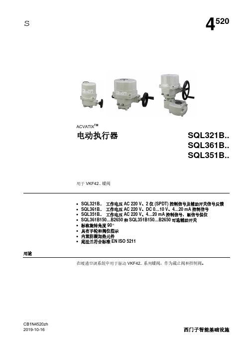
CB1N4520zh s4520ACVATIX TM电动执行器SQL321B..SQL361B..SQL351B..用于 VKF42..蝶阀·SQL321B..工作电压 AC 220 V 、2位 (SPDT)控制信号及辅助开关信号反馈·SQL361B..工作电压 AC 220 V 、DC 0…10 V 、4…20 mA 控制信号·SQL351B..工作电压 AC 220 V 、4…20 mA 控制信号,断信号保位·SQL361B150…B2650和SQL351B150…B2650可选辅助开关·标称旋转角度 90°·具有手轮和阀位指示·内置防凝加热元件·底法兰符合标准 EN ISO 5211用途在暖通空调系统中用于驱动 VKF42..系列蝶阀,作为截止阀和控制阀。
2 / 13型号概览产品型号物料编号工作电压控制信号位置反馈信号50 Hz 、90°情况下的定位时间额定扭矩[Nm]法兰连接EN ISO 5211SQL321B25S55164-A100AC 220 V 两位 (SPDT)辅助开关对1125F07SQL361B25S55164-A113AC 220 V DC 0…10 V, 4…20 mADC 0…10 V, 4…20 mA辅助开关对1125F07SQL351B25S55164-A114AC 220 V 4…20 mA 4…20 mA 辅助开关对1125F07SQL321B50S55164-A101AC 220 V 两位 (SPDT)辅助开关对2250F07SQL361B50S55164-A102AC 220 V DC 0…10 V ,4…20 mADC 0…10 V ,4…20 mA辅助开关对2250F07SQL351B50S55164-A115AC 220 V 4…20 mA 4…20 mA 辅助开关对1950F07SQL321B150S55164-A103AC 220 V 两位 (SPDT)辅助开关对39150F07SQL361B150S55164-A104AC 220 V DC 0…10 V ,4…20 mA DC 0…10 V ,4…20 mA39150F07SQL351B150S55164-A116AC 220 V 4…20 mA 4…20 mA 39150F07SQL321B270S55164-A105AC 220 V 两位 (SPDT)辅助开关对39270F10SQL361B270S55164-A106AC 220 V DC 0…10 V ,4…20 mA DC 0…10 V ,4…20 mA39270F10SQL351B270S55164-A117AC 220 V 4…20 mA 4…20 mA 39270F10SQL321B570S55164-A107AC 220 V 两位 (SPDT)辅助开关对47570F12/F10SQL361B570S55164-A108AC 220 V DC 0…10 V ,4…20 mA DC 0…10 V ,4…20 mA47570F12/F10SQL351B570S55164-A118AC 220 V 4…20 mA 4…20 mA 47570F12/F10SQL321B1400 S55164-A109AC 220 V 两位 (SPDT)辅助开关对471400F14SQL361B1400 S55164-A110AC 220 V DC 0…10 V ,4…20 mA DC 0…10 V ,4…20 mA471400F14SQL351B1400S55164-A119AC 220 V 4…20 mA 4…20 mA 471400F14SQL321B2650 S55164-A111AC 220 V 两位 (SPDT)辅助开关对1052650F16SQL361B2650 S55164-A112AC 220 V DC 0…10 V ,4…20 mA DC 0…10 V ,4…20 mA1052650F16SQL351B2650S55164-A120AC 220 V4…20 mA4…20 mA1052650F16订货执行器、蝶阀和附件均须单独定购。
西门子Acvatix调节阀与执行器产品概览说明书
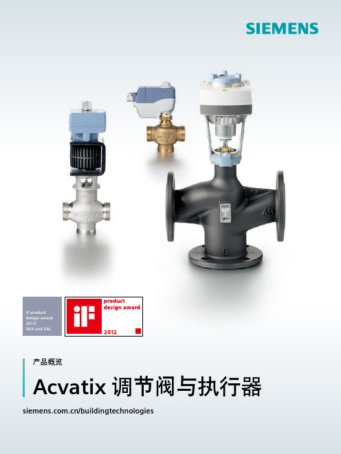
iF product design award 2012:SAX and SAL产品概览Acvatix 阀门执行器─经济高效的HVAC 系统的决定性组成部件以多年的实践经验、广泛的专业知识和先进的技术为依托,西门子推出了AcvatixTM系列阀门和执行器产品,为暖通水力系统提供理想的解决方案。
这些阀门执行器主要应用于暖通系统中的冷热源、能源分配及末端控制,并可用于区域供热。
因此,Acvatix能够满足HVAC领域以及制冷和工业应用的各种需要。
无论是单户住宅还是公寓,无论是现代办公大楼里复杂的空调还是流量非常大的设备,Acvatix阀门执行器都以高质量和长寿命著称。
他们不仅让您感到舒适、安宁,还可以在能源优化使用、项目改造中助您一臂之力。
适用于各种应用的阀门执行器产品只有机组内每个设备都能可靠、精确的运转时,HVAC 和制冷系统才能正常的工作。
来自西门子的Acvatix 产品线根据您的需要、介质类型和应用类型,总能为您提供合适的阀门执行器:- 用于小型、中型和大型HVAC 和制冷系统的阀门执行器- 用于房间、区域等末端控制的阀门执行器- 两通和三通座阀、蝶阀- 法兰、螺纹和焊接连接- 用于高精度、复杂控制系统的电磁调节阀- 带调节功能和3位或开/关控制信号的执行器地板采暖,辐射采暖TEVA 产品线,见第16页利用散热器控制区域温度TEVA 产品线,见第15和16页生活热水混合系统反应迅速的电磁调节阀, 见第5页法兰和螺纹连接的阀, 见第7-10页生活热水存储罐反应迅速的电磁调节阀,见第5页法兰和螺纹连接的阀, 见第7-10页法兰和螺纹连接的阀, 见第7-10页关闭功能蝶阀,见第13页区域供热分站法兰和螺纹连接的阀, 见第7-10页关闭冷却水塔见第13页控制风机盘管装置TEVA 产品线,见第16页冷吊顶TEVA 产品线,见第16页控制终端装置TEVA 产品线,见第16页用于空气调节设备的制冷盘管反应迅速的电磁调节阀,见第5页法兰和螺纹连接的阀,见第7-12页用于空气调节设备的供暖盘管法兰和螺纹连接的阀,见第7-12页冷冻水环路反应迅速的电磁调节阀,见第5页法兰和螺纹连接的阀,见第7-13页冷却水环路反应迅速的电磁调节阀,见第5页法兰和螺纹的阀,见第7-13页■ 实现能源优化■产品种类多样,适合于各种应用■ 便捷选择阀门执行器■高效配送- 工作电压为AC / DC 24 V 或AC 110 / 230 V 的执行器- 大量专利技术应用于各阀门或执行器,优化系统控制便捷选型西门子为您提供了各种阀门执行器的选型工具,阀门选型尺,技术资料和在线工具。
西门子风阀执行器原理

西门子风阀执行器原理西门子风阀执行器原理是指通过电动执行器来实现风阀的开启和关闭操作。
该执行器采用了先进的电动技术和控制系统,能够对风阀进行精确的控制,从而实现对空调系统的温度、湿度和风量的调节。
首先,西门子风阀执行器采用了高性能的电动机作为动力源。
电动机通过电能转化为机械能,通过转轴带动风阀的运动,实现对风阀的控制。
电动机的特点是响应速度快、调节精度高,能够满足实时调节的需求。
其次,西门子风阀执行器配备了高精度的位置传感器。
位置传感器能够实时监测风阀的开启程度,将具体的位置信息反馈给控制系统。
控制系统根据位置传感器的信号调节电动机的运行,使得风阀能够精准地达到要求的开启程度。
位置传感器可以是光电编码器、霍尔效应传感器等,具有高精度、可靠性强的特点。
此外,西门子风阀执行器还采用了先进的控制系统。
控制系统是整个执行器的核心部分,负责接收外部控制信号,并根据信号的要求调节风阀的开闭状态。
控制系统还可以根据环境温度、湿度和风量等参数来进行智能调节,实现对空调系统的自动化控制。
控制系统可以采用PLC(可编程逻辑控制器)或微处理器等硬件实现,具有高可靠性和稳定性。
最后,西门子风阀执行器还具备人性化的操作界面。
操作界面可以是触摸屏或按钮式控制面板,用户可以通过界面进行对风阀的开关、调节等操作。
同时,界面还可以显示风阀的开闭状态、运行参数等信息,方便用户对系统进行监控和管理。
总结起来,西门子风阀执行器的原理是通过电动机、位置传感器和控制系统的协同工作,实现对风阀的精确控制。
它具有响应速度快、调节精度高、自动化程度高、可靠性强等特点,适用于各类空调系统中风阀的开关控制。
西门子 ACVATIX TM SBX..,SBV.. 20…40 mm 行程 电动执行器 说明书
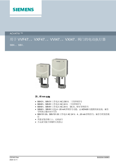
20…40 mm行程∙SBX31、SBV31工作电压 AC 230 V,三位控制信号∙SBX81、SBV81工作电压 AC 24 V,三位控制信号∙SBX61、SBV61工作电压 AC 24 V, DC 0…10 V控制信号∙SBX61、SBV61可选4…20 mA控制信号功能,由AZX420功能模块来实现,断信号时执行器回到全关位∙SBX151.00、SBV151.00工作电压AC 24 V,4…20 mA控制信号,断信号时保持阀位∙直接安装在阀门上,无需调节∙手动调节扳手和阀杆行程指示用于西门子二通阀 VVF47..、VVI47和三通阀VXF47.. VXI47..系列型号的阀门执行器,驱动行程为 20 mm和 40 mm,在暖通空调系统中作为控制阀使用。
产品型号物料编号定位信号行程驱动力工作电压 [V]运行时间[s]手动操作SBX61S55160-A100DC 0…10 V20 mm 700 N AC 24 V120手动调节扳手SBX81S55160-A101三位SBX31S55160-A102AC 230 V SBX151.00S55160-A1084…20 mA AC 24 VSBV61S55160-A103DC 0…10 V40 mm 1600 N AC 24 V180手动调节扳手SBV81S55160-A104三位SBV31S55160-A105AC 230 VSBV151.00S55160-A1094…20 mA AC 24 V 附件产品型号物料编号说明SBX31SBV31SBX81SBV81SBX61SBV61SBX151.00SBV151.00AZX420 S55845-Z120功能模块--最多1个-示例产品型号订货号说明数量SBX61S55160-A100执行器1AZX420S55845-Z120功能模块1交付执行器、阀门和附件分开包装和供货。
2二通阀关于执行器的详细信息,请参阅“电动执行器 SBX..、SBV..”的用户手册,该文档的编号是CB1P4519en。
西门子 SUA21 电动执行器 说明书
型号
型号 SUA21 订货
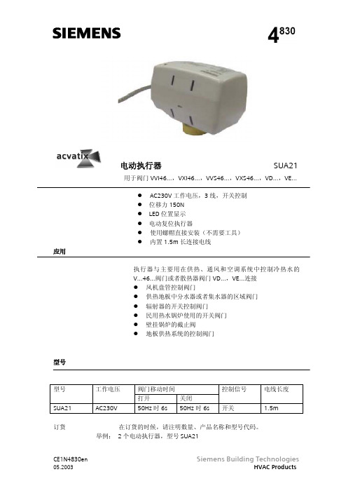
工作电压 AC230V
阀门移动时间
打开
关闭
50Hz 时 6s 50Hz 时 6s
控制信号 开关
电线长度 1.5m
在订货的时候,请注明数量、产品名称和型号代码。 举例: 2 个电动执行器,型号 SUA21
5…95%相 对湿度
尺寸
CE1N4830en
05.2003
Siemens Building Technologies
HVAC Products
线路图 N1 温控器 Y1 执行器
BK=黒色,BR=棕色,BL=蓝色
CE1N4830en
05.2003
Siemens Building Technologies
电动执行器要求一个开关控制器(温控器)来控制阀门。如果介 质的温度偏离设定值,控制输出信号会引起执行器驱动阀门打 开。当介质温度到达设定值的时候,控制信号切断,阀门再次 关闭。
注意事项
CE1N4830en
05.2003
阀门通过电由执行器打开。它包括一个同步电机和齿轮机械装 置。最大的行程由机械限制(阀座)。在末端位置没有电力ห้องสมุดไป่ตู้耗。 阀门通过 1.5m 长的电线连接,电线是执行器的一个部分。
电动执行器
SUA21
用于阀门 VVI46…,VXI46…,VVS46…,VXS46…,VD…,VE…
应用
AC230V 工作电压,3 线,开关控制 位移力 150N LED 位置显示 电动复位执行器 使用螺帽直接安装(不需要工具) 内置 1.5m 长连接电线
西门子阀门执行器介绍

W 900 R[ ]
正向调节
反向调节
输入 10...0 V 20...4 mA
1 0V 20 mA Y 0V 4 mA
0...10 V 4...20 mA 0V 4 mA
通过反向调节的功能,一个常开的阀门可以象一 个常闭阀门一样运行 (Y 0 V / 4 mA = 0%行程, Y 10 V / 20 mA = 100%行程)。但是,当执行器不 带电时弹簧回复力仍会让阀门开启 。该功能适 用于希望通过弹簧回复作用来防冻的供暖系统。
亮点
快速的定位時间 完美的低負载性能 选型過大也能达到理 想效果
Page 7
电动调节阀
应用
这是一個完美的驱动 器适合所有应用 加热 /采暖系统 冷冻水系统
Motoric portfolio
亮点
符合成本效益 通过实际考验 性能无与伦比 直接安裝在阀门上
Page 8
西门子Acvatix三种类型调节阀
动力直接传递 = 极低的磨损 -> 更长的服务寿命
0 1
(
可以选择等百分比或线 性的阀门特性
电动液压原理 直接作用的构造 =与执行器绝 对刚性连接的阀芯
Page 20
=作动稳定有力
液压执行器特性
• 强劲有力: 可达到很大的工作压差允许Δ Pmax 和关闭压差 • SR / NSR 功能 • 标准行程 • 标准控制信号 • 与阀门配套 PN6-40, DN15-150 • 与阀门直接安装 • 带手动功能 • 新的ACT电路板 • 满足CE, C-Tick and UL 认证 • 自从1975年首次投入市场以来,以在全球 安装使用了两百万个电动液压调节阀.
Y 10V 20 mA
Page 25
西门子执行器说明书
西门子执行器说明书西门子执行器说明书简介西门子执行器是一种用于控制和驱动机械设备的装置。
它可以根据输入信号执行特定的操作,如开启、关闭、调节等。
本文档介绍了西门子执行器的组成、使用方法和维护注意事项,以帮助用户更好地了解和使用该装置。
组成西门子执行器由以下几个主要部分组成:1. 电动机:负责驱动执行器进行操作。
2. 控制电路:接收输入信号并控制电动机的运行。
3. 驱动装置:将电动机的旋转运动转化为线性运动,用于推动执行器。
4. 接口模块:用于与外部设备进行连接,接收和发送信号。
使用方法在使用西门子执行器之前,请仔细阅读以下使用指南:1. 安装安装西门子执行器时,请确保按照以下步骤进行操作:1. 确保安装位置平稳且稳固,以便执行器的运动能够顺利进行。
2. 将执行器物理连接到所需的设备上,并确保连接牢固可靠。
3. 连接电源和信号线,确保正确接线,避免短路和其他电气问题发生。
2. 连接和配置连接和配置西门子执行器时,请参考以下步骤:1. 将执行器的接口模块与外部设备进行连接。
根据需要,可以选择串口、以太网或其他通信接口。
2. 配置执行器的参数,例如执行器的工作模式、速度、力度等。
根据实际需求,进行相应设置。
3. 使用和操作使用和操作西门子执行器时,请遵循以下原则:1. 根据需要,通过控制信号发送到执行器,触发相应的操作。
2. 根据执行器的反馈信号,监测操作是否成功完成。
3. 如果需要调整执行器的参数,可以重新配置执行器并重新进行连接。
维护注意事项为确保西门子执行器的正常运行和延长使用寿命,请注意以下维护事项:1. 清洁定期清洁和保养执行器的外部部件,以去除积尘和杂物。
不要使用水或其他液体直接清洗执行器,以免造成故障。
2. 定期检查定期检查执行器的连接线和接口模块,确保连接牢固可靠。
同时,检查执行器的电源线是否损坏,如有损坏应及时更换。
3. 注意避震执行器在运行过程中会产生振动,为了减少振动对执行器和周围设备的影响,可以采取一定的避震措施,如增加减震垫等。
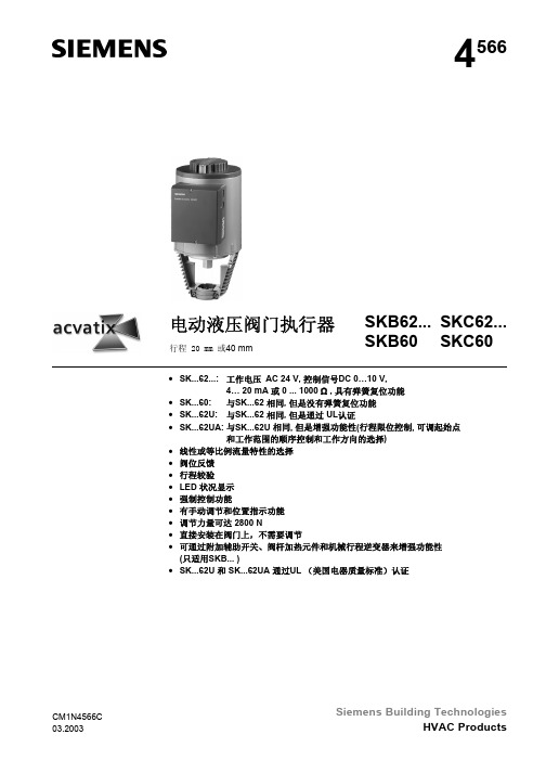
西门子电液执行器SKB62... SKC62... SKB60 SKC60 说明书
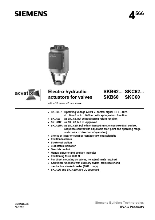
4566Electro-hydraulic actuators for valves with a 20 mm or 40 mm stroke SKB62...SKC62... SKB60SKC60•SK...62...:Operating voltage AC 24 V, control signal DC 0…10 V,4… 20 mA or 0 ... 1000 Ω , with spring-return function•SK...60:as SK...62, but without spring-return function•SK...62U:as SK...62, but UL-approved•SK...62UA:as SK...62U, but with enhanced functions (stroke limit control,sequence control with adjustable start point and operating range,and choice of direction of operation)•Choice of linear or equal-percentage flow characteristic•Position feedback•Stroke calibration•LED status indication•Override control•Manual adjuster and position indicator•Positioning force 2800 N•For direct mounting on valves; no adjustments required•Additional functions with auxiliary switch, stem heater andmechanical stroke inverter (SKB... only)•SK...62U and SK...62UA are UL-approvedCM1N4566ESiemens Building Technologies2/14ApplicationFor the operation of Siemens two-port and three-port valves, types VVF... and VXF...with a 20 mm or 40 mm stroke.• Field of application in accordance with IEC 721-3-3 Class 3K5• Ambient temperatures: −15 ... +55 °C• Temperature of medium in the connected valve: −25 ... +220 °C >220 ... 350 °C: use special extension on valve < 0 °C: type ASZ6.5 stem heater requiredFunctions• Electro-hydraulic actuators; no maintenance required • Pump, pressure cylinder and piston to open valve • Return spring and bypass valve to close valve • Manual adjuster and position indication• SK...62... with spring-return function to DIN 32730•Standard electronics:– Choice of control signal (DC 0 ... 10 V / 4 ... 20 mA / 0 ... 1000 Ω)– Choice of flow characteristic (equal-percentage / linear)– Position feedback – Stroke calibration – LED status indication– Override control via terminal Z •SK...62UA enhanced functions:– Stroke limit control– Sequence control with adjustable starting position and operating range – Choice of direction of operation (direct acting / reverse acting)• Mounting space for auxiliary switch • Stem heater can be fitted if required• Mechanical stroke inverter can be installed if required (SKB... only)•SK...62U and SK...62UA actuators are UL-approvedTypesType Operating Control Spring-return Running time Enhanced function voltage (Control signal)Function Time Opening Closing SKB62SKB62U *Yes15 sSKB60AC 24 VDC 0 ... 10 V,4 ... 20 mAor0 ... 1000 ΩNo --120 s15 sNoSKB62UA *AC 24 V DC 0 ... 10 V,4 ... 20 mAor0 ... 1000 ΩYes15 s120 s15 sStroke limit control Sequence control Signal inversionType Operating Control Spring-return Running time Enhanced function voltage (Control signal)Function Time Opening Closing SKC62SKC62U *Yes20 sSKC60AC 24 VDC 0 ... 10 V,4 ... 20 mAor0 ... 1000 ΩNo --120 s20 sNoSKC62UA *AC 24 VDC 0 ... 10 V,4 ... 20 mAor0 ... 1000 ΩYes20 s120 s20 sStroke limit control Sequence control Signal inversion* UL-approved versionsSKB... with 20 mm stroke Versions withstandard electronics Version withenhanced electronicsSKC... with 40 mm stroke Versions withstandard electronics Version withenhanced electronics3/14Type Description ASC1.6Auxiliary switch ASZ6.5Stem heater AC 24 VASK51Mechanical stroke inverter (SKB... only)OrderingWhen ordering please specify the quantity, product name and type code.Example:1 actuator, type SKC62 and1 auxiliary switch ASC1.6The actuator, valve and accessories are supplied in separate packaging and not assembled prior to delivery.Compatibility The actuators can be driven by all control systems which have an AC 24 V SELV/PELV supply and operate with DC 0 ... 10 V or 4 ... 20 mA signals.The actuators are suitable for operation of the following Siemens two-port and three-port valves with a 20 mm or 40 mm stroke:ValveDN PN Data sheet Two-port valves VV… (control valves or safety shut-off valves):VVF21... (Flange)25 ... 100 mm 6 bar 4310VVF31... (Flange)25 ... 150 mm 10 bar 4320VVF40... (Flange)15 ... 150 mm 16 bar 4330VVF41... (Flange)50 ... 150 mm 16 bar 4340VVF45... (Flange)50 ... 150 mm 16 bar 4345VVF52... (Flange)15 ... 40 mm 25 bar 4373VVF61... (Flange)15 ... 150 mm 40 bar 4382Three-port valves VX... (control valves for mixing and distribution)VXF21... (Flange)25 ... 100 mm 6 bar 4410VXF31... (Flange)25 ... 150 mm 10 bar 4420VXF40... (Flange)15 ... 150 mm 16 bar 4430VXF41... (Flange)15 ... 150 mm 16 bar 4440VXF61... (Flange)15 und 25 mm40 bar4482For admissible differential pressures ∆p max and closing pressures ∆p s , refer to the relevant valve data sheets.Third-party valves with strokes between 6 and 20 mm (SKB...) and 12 ... 40 mm(SKC...) can be motorized, provided they are «closed with the de-energized» fail-safe mechanism and provided that the necessary mechanical coupling is available.We recommend that you contact local Siemens office for the necessary information.AccessoriesDeliveryControllersMounting on linear valvesNoteTechnology4/145/14The override control input (Z) has three modes of operation:The Z-modes shown assume the factory-setting «direct-acting».To determine the stroke positions 0 and 100% in the valve, calibration is required when the valve/actuator are commissioned for the first time. For this purpose, the actuator must be mechanically connected to a Siemens valve (see «Compatibility») and must have a supply voltage of AC 24 V. The calibration procedure can be repeated as often as necessary.Before starting calibration, ensure that the manual adjuster is set to «Automatic»in order to register the actual values.There is a slot on the printed circuit boards of the actuators. To initiate the calibration procedure, the contacts inside this slot must be short-circuited (e.g. with a screwdriver).Automatic calibration proceeds as follows:• Actuator runs to the «0 stroke» position (1), valve closes, green LED flashes.• Actuator then runs to the «100 stroke» position(2), valve opens, green LED flashes.• Measured values are stored.The calibration procedure is finish, and the green LED now glows steadily (normal operation).• The actuator now moves to the position defined by control signal Y or Z (3).0%t100%Stroke123• Throughout this procedure, output U is inactive, i.e. the values only represent actual positions when the green LED stops flashing and remains on continuously.LED Display FunctionActionGreenOn • Normal operationAutomatic operation, no problems Flashing• Stroke calibration in progress Wait until calibration is complete (LED stops flashing)RedOn• Faulty stroke calibration• Internal error Check mountingRe-start stroke calibration(by short-circuiting calibration slot)Replace electronics Flashing • Inner valve jammed Check the valve Off• No power supply •Faulty electronicsCheck mains Replace electronicsOverride control NoteStroke calibrationLED status indicationConnectionterminals Stroke calibrationLED status indicationDIL switchesFunctions see below ONOFFDIL switches Selection ofcontrol signal Selection offlow characteristicON DC 4 ... 20 mA Linear* OFF DC 0 ...10 V Equal percentageConnectionterminalsStroke calibrationRotary switches LOand UPLEDstatus indication6/147/14• With normally-closed valves, «direct-acting» means that with a signal input of 0 V,the valve closes (applies to all Siemens valves listed under «Compatibility» on page 3)• With normally-open valves, «direct-acting» means that with a signal input of 0 V, the valve is open.4 mA 0 Ω20 mA 1000 ΩThe mechanical spring-return function is not affected by the direction of operation selected.*The smallest adjustment is 3 V;control with 0…30 V is only possible via Y.Selecting the direction of operationNoteStroke limit control and sequence control8/14ASC1.6 auxiliary switch –Switching point 0 … 5 % stroke5434561Z 08ASZ6.5 stem heater − For media below 0°C − Mount between valve and actuatorEngineering notesThe actuators must be electrically connected in accordance with local wiring regulations and with the wiring diagram on page 12.Regulations and requirements designed to ensure the safety of people and property must be observed at all times.The ASZ6.5 stem heater has a heat output of 30 VA and is required to keep the valve stem free of ice in the cooling range 0 °C ... −25 °C. In this case, in order to ensure adequate air circulation, the actuator bracket and the valve stem must not be insulated. Physical contact with unprotected hot components can cause burns.Failure to observe the above advice can result in accidents or fire.The admissible temperatures (see «Application» and «Technical data») must be observed.Mounting instructionsPermissible Not permissibleInstructions for fitting the actuator to the valve are bypacked in the actuator packaging.The instructions for accessories are enclosed with the accessories themselves.Accessories Orientation9/14Commissioning notesWhen commissioning the system, check the wiring and functions, and set any auxiliary switches, potentiometers and stroke limit devices as necessary, or check the existing settings.Cylinder with valve stem connector fully retracted → stroke = 0 %Cylinder with valve stem connector fully extended → stroke = 100 %The manual adjuster must be rotated counterclockwise to the end stop.This causes the Siemens valves, types VVF... and VXF... to close (stroke = 0%).For automatic operation, the crank (2) on the manual adjustment knob (1) must be engaged. If not engaged, turn the crank counter-clockwise until the display window (3)neither shows the scale (4) nor the crank engagement bar.124564Z 144564Z 16Engaged crank (2) on the manual adjustment knob (1)Display window with invisible scale dial and crank engagement barFor manual operation, swing out the crank (2) so that the display window (3) becomes visible. By rotating the crank or the manual adjustment knob (1), the display window shows the engagement bar and/or the scale dial with stroke indication.34564Z 154Swung-out crank,display window (3)Display window with scale dial (4)and stroke indicationAutomatic operationManual operation10/14MaintenanceWhen servicing the valve:• Switch OFF the pump and power supply, close the main shut-off valves in the pipework, release pressure in the pipes and allow them to cool down completely. If necessary, disconnect electrical connections from terminals.• The valve must be re-commissioned only with the actuator correctly assembled.DisposalThe actuator includes electrical and electronic components and must not be disposed of as domestic waste.Current local legislation must be observed .WarrantyThe application-related technical data (∆ p max , ∆ p s , leakage, noise levels and service life) is valid for the Siemens actuators only in conjunction with the Siemens valves listed in the section on «Compatibility».Before using these actuators with third-party valves, written approval must be obtained from Siemens Building Technologies. A failure to obtain this approval invalidates any guarantee.Technical data Power supplyOperating voltage (SELV, PELV)AC 24 V –20 % / +30 %Frequency50 or 60 Hz Power consumption SKB62... SKB60 SKC62... SKC6017 VA / 12 W 13 VA / 10 W 28 VA / 20 W 24 VA / 18 WExternal supply cable fuse SKB... SKC...Min. 1 A slow blow,max. 10 A slow blow Min. 1,6 A slow blow,max. 10 A slow blowOperating dataType of control (proportional)DC 0 ... 10 V, DC 4 ... 20 mA or 0 ... 1000 ΩRunning time at 50 Hz SKB... SKC...Opening 120 s 120 s Closing 15 s 20 s Spring-return time (closing) SKB... SKC...15 s20 sNominal stroke SKB... SKC...20 mm40 mm Positioning force 2800 NFlow characteristicLinear / equal percentage can be selected ** in conjunction with valves listed under «Compatibility» on page 3Signal inputs Terminal YVoltageInput impedance CurrentInput impedance Signal resolution Hysteresis DC 0 ... 10 V 100 kΩDC 4 ... 20 mA 240 Ω<1 %1 %Terminal ZResistance0 ... 1000 ΩOverride control functionsZ not connectedZ connected directly to GZ connected directly to G0Z connected to M via 0 ... 1000 ΩNo function (priority at Terminal Y) Max. stroke 100 %Min. stroke 0 %Linear / equal percentageSignal outputs Terminal UVoltageLoad impedance CurrentLoad impedance DC 0 ... 9.8 V ±2 %>500 ΩDC 4 ... 19.6 mA ±2 % <500 ΩGeneralambient conditions Maximum admissible temperature ofmedium in the connected valve:≤220 °C OperationEnvironmental conditionsTemperatureHumidityTo IEC 721-3-3Class 3K5–15 ... +50 °C5 ... 95 % rh TransportEnvironmental conditionsTemperatureHumidityTo IEC 721-3-2Class 2K3–30 ... +65 °C<95 % rh StorageEnvironmental conditionsTemperatureHumidityTo IEC 721-3-1Class 1K3–15 ... +50 °C5 ... 95 % rhIndustry standards Meets the requirements for CE marking inEMC DirectiveLow Voltage Directive 89/336/EEC 73/23/EECElectromagnetic compatibilityEmitted interference Interference immunity EN 61000-6-3 Residential EN 61000-6-2 IndustrialProduct standards for automaticelectric controls EN 60 730-2-14C-tick N474Protection standard IP54 to EN 60529Protection class III to EN 60730UL approval UL 873 Dimensions See «Dimensions»Weight SKB...SKC...ASK51 stroke inverter8,60 kg(including packaging) 10,00 kg(including packaging) 1,10 kg(including packaging)Materials Actuator housing and bracketHousing box and manual adjuster Die-cast aluminum PlasticCable glands SK...62, SK (60)SK...62U, SK...62UA Pg 11 (4 x)Pg 16 (4 x)11/1412/14SK...62UA enhanced functions Direction of operationDirect acting / reverse actingDC 0 ... 10 V / DC 10 ... 0 V DC 4 ... 20 mA / DC 20 ... 4 mA 0 ... 1000 Ω / 1000 ... 0 ΩStroke limit control Range of lower limit Range of upper limit 0 ... 45 % adjustable 100 ... 55 % adjustable Sequence controlTerminal YStarting point of sequence Operating range of sequence0 ... 15 V adjustable 3 ... 15 V adjustableAccessoriesASC1.6 auxiliary switch Switching capacity of auxiliary switch AC 24 V, 10 mA ... 4 (2) A ASZ6.5 stem heaterOperating voltagePower consumption (heat output)AC 24 V ±20 %30 VAConnection diagramA C 24 VB1SensorF1Temperature limiter N1Controller Y1ActuatorU ZG0G Y M Operating voltage AC 24 V System neutral (SN)Operating voltage AC 24 V System potential (SP)Control signal DC 0 ... 10 (30) V or DC 4 ... 20 mA Measuring neutral (= G0)Position indication DC 0 ... 10 V or DC 4 ... 20 mA Override input (functions see page 5)c134501804Connection terminalsASC1.6auxiliary switch13/14DimensionsAll dimensions in mm*Height of actuator from valve plate without stroke inverter ASK51 = 300 mm Height of actuator from valve plate with stroke inverter ASK51 = 357 mm **The hole diameter on the SK...62U... actuators corresponds to the Pg16 gland.s =>100 mm Minimum clearance from ceiling or wall for mounting,ss =>200 mm connection, operation, maintenance etc.20*109,535444456,5108∅∅4561M 02* Maximum stroke = 20 mmASK51 stroke inverter14/14© 2002 Siemens Building Technologies Ltd.Subject to alteration。
西门子 SKC32.. 24V 电液伺服执行器 使用手册说明书

with a40 mm stroke● SKC32.. Operating voltage AC 230 V, 3-position control signal● SKC82.. Operating voltage AC 24 V, 3-position control signal● SKC6.. Operating voltage AC 24 V,– Control signal DC 0...10 V, 4...20 mA or 0...1000 Ω– SKC62/MO RS-485 for Modbus RTU communication– Selection of flow characteristic, position feedback, stroke calibration, LED status indication, override control– SKC62UA with selection of direction of operation, stroke limit control, sequence control with adjustable start point and operation range, operation of frost protection monitors QAF21.. and QAF61..● Positioning force 2800 N● Versions with or without spring-return function● For direct mounting on valves; no adjustments required● Manual adjuster and position indicator● Optional functions with auxiliary switches, potentiometer and stem heater● SKC..U are UL-approvedFor the operation of Siemens 2-port and 3-port valves of the types VVF.. and VXF.. with a 40 mm stroke as control and safety shut-off valves in heating, ventilation and air conditioning systems.Principle of electro-hydraulic actuators1 Manual adjuster2 Pressure cylinder3 Suction chamber4 Return spring5 Solenoid valve6 Hydraulic pump7 Piston8 Pressure chamber9 Position indicator (0 to 1)10 Coupling11 Valve stem12 PlugValve closed Valve openedOpening thevalveThe hydraulic pump [6] forces oil from the suction chamber [3] to thepressure chamber [8], thereby moving the pressure cylinder [2] downwards.The valve stem [11] retracts and the valve opens. Simultaneously, the returnspring [4] is compressed.Closing thevalveActivating the solenoid valve [5] allows the oil in the pressure chamber toflow back into the suction chamber. The compressed return spring movesthe pressure cylinder upwards. The valve stem extends and the valvecloses.ManualoperationmodeFor manual operation, swing out the crank so that the display windowbecomes visible. By rotating the crank clockwise, the pressure cylinder ismoved downwards. The display window shows the engagement bar and/orthe scale dial with stroke indication.In the manual operation mode, the positioning signals Y and Z can furtheropen the valve but cannot move to the 0 % stroke position of the valve. Toretain the manually set position, switch off the power supply or disconnectthe positioning signals Y and Z. The crank remains swung out and in thedisplay window the red indicator dial remains visible.Hinweis:When setting the controller to manual operation for a longerperiod of time, we recommend adjusting the actuator with themanual adjuster to the desired position. This guarantees thatthe actuator remains in this position for that period of time.Attention: Do not forget to switch back to automatic operationafter the controller is set back to automatic control.2Automatic operation mode For automatic operation, turn the manual adjuster clockwise to the end stop. The pressure cylinder moves upwards to the 0% stroke position of the valve. In the display window, the read scale disappears. Afterwards, swing the crank closed.Minimal volumetric flow The actuator can be manually adjusted to a stroke position > 0%, allowing its use in applications requiring a constant minimal volumetric flow.SKC32.. SKC82..3-position control signal The actuator is controlled by a 3-position signal either via terminals Y1 or Y2 and generates the desired stroke, which is transferred to the valve stem:● Voltage on Y1: Piston extends Valve opens● Voltage on Y2: Piston retracts Valve closes● No voltage on Y1 and Y2: Piston and valve stem remain in therespective positionSKC62.. SKC60Y positioning signalDC 0...10 V and/or 0...1000 Ω, DC 4...20 mA The actuator is either controlled via terminal Y or override control Z. The positioning signals generate the desired stroke by means of the above described principle of operation, which is transferred to the valve stem: ● Signal Y increasing: Piston extends Valve opens ● Signal Y decreasing: Piston retracts Valve closes ● Signal Y constant: Piston and valve stem remain in therespective position● Override control Z: See Functions [➙8]Frost protection monitor Frost protection thermostat A frost protection thermostat can be connected to the SKC6.. actuator. The added signals from the frost protection monitors QAF21.. and QAF61..require the use of SKC62UA actuators. Notes on special programming of the electronics are described under Electronics [➙5].Connection diagrams for operation with frost protection thermostat or frost protection monitor can be found under Connection diagrams [➙26].4ElectronicsSKC601)1 Connection terminals2 DIL switches3 LED status indication 4Stroke calibration1) From version ..L onwardSKC60 2), SKC62..1 Connection terminals2 DIL switches3 LED status indication 4Stroke calibration2) Up to and including version ..KSKC62UA1 Connection terminals2 DIL switches3 LED status indication4 Stroke calibration5 Rotary switch UP (factory setting 0) 6Rotary switch LOSKC62/MOThe Modbus converter is designed for analog control at 0...10 V.Keep the analog signal setting on the actuator as is (switch 1 to OFF); adjustment notpermitted.The actuators are factory configured for equal-percentage characteristic.DIL switch (internal actuator characteristic changeover) to "log" (switch 2 to OFF).FunctionsSpring-return functionThe SKC32.61.., SKC82.61.. and SKC62.., which feature a spring-return function,incorporate a solenoid valve which opens if the control signal or power fails. The returnspring causes the actuator to move to the 0% stroke position and closes the valve.CalibrationSKC60, SKC62.., SKC62/MOIn order to determine the stroke positions 0% and 100% in the valve, calibration is requiredon initial commissioning.♦Mechanical coupling of the actuator SKC6.. with a Siemens valve.Actuator must bin in …Automatic operation mode“ enabling stroke calibration to capture the effective 0% and 100% values.♦AC 24 V power supply applied.♦Housing cover removed.1.Short-circuit contacts in calibration slot (e.g. with ascrewdriver) and trigger calibration process.2. Actuator moves to 0% stroke position [1].♋Valve closes.3. Actuator moves to 100% stroke position [2].♋Valve opens.♋Measured values are stored. LED flashes grün, positioningfeedback U inactive♋Normal operation:Actuator moves to the position [3] as indicated by signalsY or Z.LED is lit green permanently, positioning feedback Uactive, values correspond to the actual positions.A red lit LED on the actuator indicates a calibration error.6The LED on the SKC62/MO cable adapter flashes red during the calibration, as the positioning signal Y and the positioning feedback U do not correspond anymore. This is interpreted as a blockage and thus indicated as an error.necessary, the calibration can be repeated any number of times.LED indication of operational statusSKC60, SKC62.., SKC62/MOThe dual-colored LED indicating the operational status is visible when the cover is removed.As a general rule, the LED can only assume the states shown above – continuously lit red or green, flashing red or green, or off/dark.8Override control ZSKC60, SKC62..The override control input Z can be operated in the following modes of operation:Shown operation modes are based on the factory setting “direct acting”.Y-input has no effect in Z-mode..Selection of direction of operationSKC60 (from version ..L), SKC62UA● With normally-closed valves, “direct acting” means that with a signal input of 0 V, thevalve closes (applies to all Siemens valves listed under Equipment combinations [➙12]). ● With normally-open valves, “direct acting” means that with a signal input of 0 V, the valveis open.The mechanical spring-return function is not affected by the direction of operation selected.Stroke limit control and sequence controlSKC62UA* Operating range of QAF21.. (see below)** Operating range of QAF61.. (see below)*** The smallest adjustment possible is 3 V; control with 0...30 V is only possible via Y.Stroke control with QAF21.. / QAF61.. signal additionSKC62UA101) Approbation: CE 2) Approbation: CE, UL 3) Only available in France4) Enhanced functions, from version ..L onward: Direction of operation, fail-in-place5)Enhanced functions: Direction of operation, stroke control limit, sequence control, signal additionScope of deliveryThe actuator, valve and accessories are supplied in separate packaging and not assembled prior to delivery.Accessories / spare partsAccessories0…1000 ΩFor the combination SIMATIC S5/S7 and use of positioningfeedback, we recommend actuators with DC 0...9.8 VThe signal peaks that occur in the potentiometer ASZ7.3may result in error messages on Siemens SIMATIC. This isnot the case when combined with Siemens HVACcontrollers. The reason is that SIMATIC has a higherresolution and faster response time.Use the potentiometer as voltage divider on the 3-wireconnection. Powering the potentiometer over the wiper mayshorten the life cycle of the potentiometer. Signal peaksincrease in frequency and scope over the lifespan in this For more information, see Technical data [➙19]Ordering (example)1)Specify stock number if available.Spare parts1)Hand control, blue with mechanical partsEquipment combinations2-port valves VV.. (control or safety shut-off valves)Admissible differential pressures Δp max and closing pressures Δp s: cf. relevant valve data sheets1)Valves are no longer available3-port valves VX.. (control valves for “mixing” and “distribution”)Admissible differential pressures Δp max and closing pressures Δp s: cf. relevant valve data sheets1)Valves are no longer availableThird-party valves with strokes between 6...20mm can be motorized, provided they are “closed with the de-energized” fail-safe mechanism and provided that the necessary mechanical coupling is available. For SKC32.. and SKC82.. the Y1 signal must be routed via an additional, freely adjustable end switch (ASC9.3) to limit the stroke.We recommend that you contact your local Siemens office for the necessary information.Related documents such as environmental declarations, CE declarations, etc., can be downloaded at the following Internet address:/bt/downloadSafetyEngineeringConduct the electrical connections in accordance with local regulations on electricalinstallations as well as the section Connection diagrams [➙26].Observe admissible temperatures, see Use [➙2] and Technical data [➙19].If an auxiliary switch is used, its switching point should be indicated on the plant schematic.Every actuator must be driven by a dedicated controller, see Connection diagrams [➙26].Mounting Instructions 74 319 0324 0 for fitting the actuator to the valve and A5W00027551 for SKC62/MO are enclosed in the actuator packaging. The instructions for accessories are enclosed with the accessories themselves (see Product documentation [➙13]).Mounting positionsCommissioningWhen commissioning the system, check the wiring and functions, and set any auxiliary switches and potentiometers as necessary, or check the existing settings.The manual adjuster must be rotated counter-clockwise to the end stop.This causes the Siemens valves, types VVF.. und VXF.. to close (stroke = 0 %).Automatic operationFor automatic operation, the crank [2] on the manual adjustment knob [1] must be engaged.If not engaged, turn the crank counter-clockwise until the display window [3] shows neitherthe scale [4] nor the crank engagement bar.Manual operationFor manual operation, swing out the crank [2] so that the display window [3] becomes visible.By rotating the crank or the manual adjustment knob [1], the display window shows theengagement bar and/or the scale dial [4] with stroke indication.Engaged crank [2] on the manual adjustment knob [1]Swung-out crank; display window [3] Display window with scale dial [4] and stroke indicationin mmMaintenanceThe actuators are maintenance-free.When servicing the control device:WARNINGRisk of burns from hot actuator bracketsThe actuator brackets on heating plants can also become hot from the contact with the hotRecommendation SKC6..:Trigger stroke calibration after maintenance.Repair:See Spare parts [➙12]DisposalWarrantyTechnical data on specific applications are valid only together with Siemens products listedunder "Equipment combinations". Siemens rejects any and all warranties in the event thatthird-party products are used.1)At room temperature (23 °C); low ambient temperatures or high Δp may prolong these times2)From version ..L onward3)AWG = American wire gauge4)The documents can be downloaded at /bt/downloadInternal diagramsSKC32..SKC82..SKC6..Connection terminalsSKC6..SKC62/MOAuxiliary switch ASC1.6Connection diagramsSKC32..*)Only SKC62UA: only with sequence control and the appropriate selector switch settings, see Electronics [➙5], Functions [➙6]ActuatorControllerSystem potentialSystem neutralReference line (Modbus RTU) Bus + (Modbus RTU)Bus - (Modbus RTU)ActuatorAll dimensions in mmExternal Modbus converterAll dimensions in mm。
SIEMENS 电动执行器SQL35.00 85.00 36E65 36E110 说明书

这类执行器和 ASK35.1 或 ASK35.2 安装套件一起配套安装。
这类执行器直接安装在 VKF46... 系列蝶阀上
阀门、执行器和安装套件独立包装。阀门和执行器可以在现场无需任何特殊工具直接组 装。 安装阀门时注意方向朝上,可以参见安装说明。
90
90
.
.
.
.
.
4716Z16
.
4/10
Building Technologies HVAC Products
电阻变化
至 90° 的动作时间 50 Hz 时
AC 250 V, 10 A 电阻性, 3 A 电感性 大约 1° 0...1’000 Ω 对应..90°
30...180 s
重量 . .
60 g .
.
50 g . .
60 g .
Building Technologies HVAC Products
电动执行器
电动执行器
CA1N4505en 10.01.2005
选件 SQL35/85…
ASC9.5 辅助开关
«AUTO» / «MAN» 旋钮 手杆 架
接线排 双末端开关 * 用于旋转方向反向的插销
* 出厂安装
ASC9.4 双辅助开关
ASZ7.4 辅助开关和 1000 Ω电位计
4554Z04 4554Z06 4554Z05
±15 %
±20 % –5 / +10 % –5 / +10 %
50 / 60 Hz
6.5 VA
160 VA 三位
235 VA
无法实现
125 s
6 s 2)
12 s 3)
105 s
5s
10 s
西门子 SQX32. SQX82. SQX62.电动阀门执行器 说明书

4554电动阀门执行器SQX32...SQX82...SQX62...行程20 mm• SQX32…: AC 220V 工作电压, 接受三位控制信号 • SQX82...: A C 24 V 工作电压, 接受三位控制信号 • SQX62...: A C 24 V 工作电压,DC 0…10 V 和/或 0...1000 Ω 或DC 4...20 mA 阀位信号 • 通过附加辅助开关和电位计来增强功能性 • 调节力量可达 700 N • 行程 20 mm• 不需要其他设置工具可以直接与阀体安装 • 有手动调节和位置显示功能• SQX82…U 和 SQX62U 通过UL 认证用于二通阀、三通阀 V VF …, VVG …, VPF …, VXF …, VXG …系列型号的阀门执行器, 驱动行程为20mm 。
用途应用领域符合 IEC 721-3-3 (国际电工委员会721-3-3规定) 3K5 等级 • 环境温度: -15...+50 °C• 阀内介质温度: -25...+140 °C>140°C 使用S K B...系列执行器 < 0 °C: 要求使用阀杆加热元件ASZ6.5功能异步电机可通过端子Y1或Y2 输出的三位控制信号进行控制,通过抗阻碍齿轮链及齿轮架产生所希望的阀位行程。
SQX32..., SQX82... 三位控制信号• Y1 端有电压: 阀杆收缩,阀门打开 • Y2 端有电压: 阀杆伸长,阀门关闭 • Y1 或Y2 端无电压 阀杆保持在当前位置 SQX62... 是通过端子Y 和/或R.信号进行控制。
记录的位置信号通过电子微处理器控制同步电机,电机t 通过抗阻碍齿轮链及齿轮架产生所希望的阀位行程。
SQX62, SQX62U阀位信号:DC 0...10 V 和/或0...1000 Ω 或 DC 4...20 mA• 阀位信号 Y, R 值增大: 阀杆收缩,阀门打开 • 阀位信号 Y, R 值减小: 阀杆伸出,阀门关闭 • 阀位信号 Y, R 不变: 阀杆保持在各自原位通过调节滑片(外壳下面的电路板上) ,可实现VVF... , VVG…, VXF…, VXG…和 VPF...的流量特性从 "等百分比" 转换成 "线性"。
西门子(Siemens)3SB3500-4AD01 22mm圆形金属执行器说明书

3SB3500-4AD01
22MM ROUND METAL ACTUATOR: RONIS LOCK WITH 2 KEYS MAINTAINED CONTACT 2 SWITCH POSITIONS O-I LOCK NUMBER SB 30, REMOVE O WITH HOLDER POSSIBLE SPECIAL LOCKS FOR RONIS KEYSWITCHES: SB31, 455, 421
3SB3500-4AD01 Page 2/3
18.08.2014
subject to modifications © Copyright Siemens AG 2014
Industry Mall (网上订购系统) /industrial-controls/mall
正树/批准: General Product Approval
Shipping Approval
金属
<= 50g
20 ... 200 Hz: 5g
1/h
1,000
300,000
否
S
S
N·m
1
°C
-25 … +70
°C
-40 … +80
IP67
3K6
正面固定
圆形的
mm
28.5
mm
22
mm
44ation of Conformity
执行器/信号装置: 产品的结构形式 操作元件的结构形式 外部直径 / 操控元件的 工作原理 / 操作元件 解锁方式 颜色 / 操纵元件的 材料的 / 操纵元件的 挂锁厂家 换档位置的数目 钥匙拔出时的开关位置 开关角度
• 向右 产品组件 / 正面固定环 材料 / 正面固定环 颜色 / 正面固定环的 前置垫圈规格 产品功能 / 急停功能
SKC60-62液压执行器 西门子

AP1N4566zh 西门子楼宇科技暖通空调产品4566电动液压阀门执行器行程 20 mm 或 40 mm SKB62... SKC62... SKB60 SKC60•SK...62...:工作电压 AC 24 V,控制信号 DC 0–10 V,4–20 mA 或 0–1000 Ω,具有弹簧复位功能•SK...60:参考 SK...62,无弹簧复位功能•SK...62U:参考 SK...62,通过 UL 认证•SK...62UA:参考 SK...62U 参考,功能加强(动作方向选择、行程限位控制、可调起始点和工作范围的顺序控制和附加防冻保护监控信号 QAF21…及QAF61…)•驱动力达 2800 N•可选的流量特性:等百分比或线性•阀位反馈•行程调校•LED 状况显示•优先控制功能•有手动调节和位置指示功能•直接安装在阀门上,不需要调节•可通过附加辅助开关、阀杆加热器和机械行程逆变器来增强功能性(仅 SKB... 适用)•SK...62U 和 SK...62UA 通过 UL 认证2/14应用用于西门子二通阀和三通阀 VVF... 和 VXF... 系列阀门,驱动行程为 20 mm 或 40 mm ,应用于暖通空调系统中作为控制阀或安全截止阀。
型号型号 工作电压控制信号弹簧复位 运行时间 加强功能功能 时间开启 关闭SKB62 SKB62U * 有 15 秒 SKB60AC 24 VDC 0–10 V ,4–20 mA或0–1000 Ω无--120 秒 15 秒 无SKB62UA * AC 24 VDC 0–10 V,4–20 mA或0–1000 Ω有 15 秒120 秒 15 秒 动作方向行程限位控制 顺序控制 附加信号型号 工作电压控制信号弹簧复位 运行时间 加强功能功能 时间开启 关闭SKC62SKC62U * 有 20 秒 SKC60AC 24 VDC 0–10 V,4–20 mA或0–1000 Ω无--120 秒 20 秒 无SKC62UA * AC 24 VDC 0–10 V,4–20 mA或0–1000 Ω有 20 秒120 秒 20 秒 动作方向行程限位控制 顺序控制 附加信号* UL 认证版本型号 描述 ASC1.6 辅助开关ASZ6.5 阀杆加热器 AC 24 VASK51机械行程逆变器(仅SKB...适用)订货订货时请说明执行器数量、产品名称和型号。
西门子SQS…电动执行器
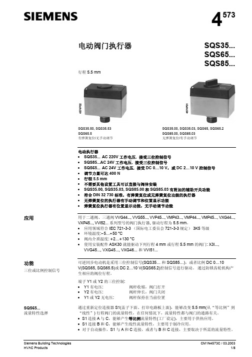
行程 5.5 mm
4573
SQS35... SQS65... SQS85...
应用
功能
三位或比例控制信号
SQS65... 流量特性选择
SQS35.50, SQS35.53 SQS65.5 有弹簧复位/无手动调节
SQS35.00, SQS35.03, SQS65, SQS65.2 SQS85.00, SQS85.03 无弹簧复位/有手动调节
执行器、阀门及附件分开包装,在发货前不装配在一起。
弹簧复位时间 [秒] --8 8 ---
空间用于 1 x ASC9.6
下列 5.5 mm 行程、螺纹二通和三通阀门可由电动执行器 SQS35... , SQS65...和 SQS85... 来驱动:
型号 二通阀
VVG44... VVP45... VMP43...(2) VMP44...(2) VVG55... VVI52... 三通阀
器。执行器型号 SQS35.50 和 SQS35.53 按标准内安装辅助开关(不是 ASC9.6)。
4573Z03 S1
A C B R-M
1
2
SQS35.00, SQS35.03
SQS65, SQS65.2
SQS85...
1 手动调节 2 位置指示器 3 阀颈的连接螺栓
3
01163
S1
A C B R-M
DN [mm]
15…40 10…20 15, 20 15, 20 15…25
15
PN [Bar]
16 16 16 16 25 25
技术资料
N4364 N4845 N4841 N4844 N4379 N4377
Siemens Building Technologies HVAC Products
西门子 电动执行器 SQN7 说明书

SQN71.694A20 ---
SQN7... 替代类型 参考
SQN31.151A2700 SQN31.101A2700
-------
--SQN31.401A2700
---
执行器 SQN74... / 逆时针旋转 8)
图纸编号.
驱动轴¹) 50Hz 时的行 额定扭矩 6) 保持转矩
AS
编号.
程时间 2)
+10 % -15 %
50...60 Hz
50...60 Hz
SQN70.224A20
---
SQN70.244A20
---
SQN70.264A20
---
SQN70.294A20
---
SQN70.324A20
---
SQN70.424A20
---
SQN70.454A20
---
SQN70.464A20
---
CC1N7804en 2/20/2006
机械设计 外壳
- 耐压和抗热塑料壳体组成 - 内部包括:
– 齿轮连接的同步电动机,带由齿轮离合装置 – 控制部分的凸轮轴 – 继电器,因驱动器的类型不同而定 – 开关,与印刷电路板上的端子连接
颜色: SQN70... / SQN71...: SQN74... / SQN75...:
执行器 SQN70... / 顺时针旋转 8)
图纸编 驱动轴¹) 50Hz 时的行程 额定扭矩 保持转 AS
号.
编号.
时间 2) 转到 90°
6)
矩
7)
(最大.) Nm
s
Nm
pcs.
2
04Βιβλιοθήκη 1.50.72
SIEMENS 电动液压阀门执行器 说明书
25 ... 150 mm
VXF40... (法兰)
15 ... 150 mm
VXF41... (法兰)
15 ... 150 mm
VXF61... (法兰)
15 和 25 mm
PN
6 bar 10 bar 16 bar 16 bar 16 bar 25 bar 40 bar
6 bar 10 bar 16 bar 16 bar 40 bar
和工作范围的顺序控制和工作方向的选择) • 线性或等比例流量特性的选择 • 阀位反馈 • 行程较验 • LED 状况显示 • 强制控制功能 • 有手动调节和位置指示功能 • 调节力量可达 2800 N • 直接安装在阀门上,不需要调节 • 可通过附加辅助开关、阀杆加热元件和机械行程逆变器来增强功能性
? G0
Fully open Fully closed
Input override
? 0 ...1000 Ω
0 ...100 %
(Signal priority)
Pump Solenoid
Y
DC 0 ...10 V or
0 ...100 %
Input
Valve Seat Detection
Stroke
型号 SKB... 行程 20 mm 标准版
功能增强版
SKC... 行程 40 mm 标准版
功能增强版
2/13 Siemens Building Technologies HVAC Products
型号
工作电压
SKB62 SKB62U *
AC 24 V
SKB60 SKB62UA * AC 24 V
控制 (控制信号)
– 控制信号的可选性 (DC 0 ... 10 V / 4 ... 20 mA / 0 ... 1000 Ω) – 流量特性的可选性 (等比例 / 线性) – 阀位反馈 – 行程较验 – LED 状态显示 – 通过端子Z 的强制控制 • SK...62UA 功能增强版: – 行程限位控制 – 可调起始点和工作范围的顺序控制 – 工作方向的选择 (正向动作 /反向动作) • 有辅助开关的安装空间 • 如果需要可使用阀杆加热元件 • 如果需要可安装机械行程逆变器 (只适用SKB...) • SK...62U 和 SK...62UA 执行器通过UL (美国电器质量标准)认证
西门子风阀执行器型号大全
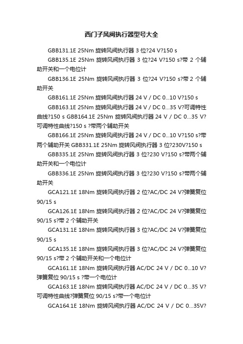
西门子风阀执行器型号大全GBB131.1E 25Nm 旋转风阀执行器 3 位?24 V?150 sGBB135.1E 25Nm 旋转风阀执行器 3 位?24 V?150 s?带 2 个辅助开关和一个电位计GBB136.1E 25Nm 旋转风阀执行器 3 位?24 V?150 s?带2 个辅助开关GBB161.1E 25Nm 旋转风阀执行器24 V / DC 0...10 V?150 sGBB163.1E 25Nm 旋转风阀执行器24 V / DC 0…35 V?可调特性曲线?150 s GBB164.1E 25Nm 旋转风阀执行器24 V / DC 0…35 V?可调特性曲线?150 s ?带两个辅助开关GBB166.1E 25Nm 旋转风阀执行器24 V / DC 0...10 V?150 s?带两个辅助开关GBB331.1E 25Nm 旋转风阀执行器 3 位?230V?150 s GBB335.1E 25Nm 旋转风阀执行器 3 位?230 V?150 s?带两个辅助开关和一个电位计GBB336.1E 25Nm 旋转风阀执行器 3 位?230 V?150 s?带两个辅助开关GCA121.1E 18Nm 旋转风阀执行器 2 位?AC/DC 24 V?弹簧复位90/15 sGCA126.1E 18Nm 旋转风阀执行器 2 位?AC/DC 24 V?弹簧复位90/15 s?带2 个辅助开关GCA131.1E 18Nm 旋转风阀执行器 3 位?AC/DC 24 V?弹簧复位90/15 sGCA135.1E 18Nm 旋转风阀执行器 3 位?AC/DC 24 V?弹簧复位90/15 s?带2 个辅助开关和一个电位计GCA161.1E 18Nm 旋转风阀执行器AC/DC 24 V / DC 0...10 V?弹簧复位90/15 s ?带一个电位计GCA163.1E 18Nm 旋转风阀执行器AC/DC 24 V / DC 0…35 V?可调特性曲线?弹簧复位90/15 s?带一个电位计GCA164.1E 18Nm 旋转风阀执行器AC/DC 24 V / DC 0…35V?可调特性曲线?弹簧复位90/15 s?带2 个辅助开关和一个电位计GCA166.1E 18Nm 旋转风阀执行器AC/DC 24 V / DC 0...10 V?带弹簧复位90/15 s?带2 个辅助开关和电位计GCA321.1E 18Nm 旋转风阀执行器2 位?AC230 V?带弹簧复位90/15 sGCA326.1E 18Nm 旋转风阀执行器2 位?AC230 V?带弹簧复位90/15 s? 2 个辅助开关GDB131.1E 5Nm 旋转风阀执行器 3 位?AC24V?150 sGDB132.1E 5Nm 旋转风阀执行器 3 位?AC 24V?150 s?带一个电位计GDB136.1E 5Nm 旋转风阀执行器 3 位?AC 24V?150 s?带两个辅助开关GDB161.1E 5Nm 旋转风阀执行器AC 24 V / DC 0...10 V?150 s?带一个电位计GDB163.1E 5Nm 旋转风阀执行器AC 24 V / DC 0...10 V?可调特性曲线?150 s?带一个电位计GDB164.1E 5Nm 旋转风阀执行器AC 24 V / DC 0...10 V?可调特性曲线?150 s带两个辅助开关和一个电位计GDB166.1E 5Nm 旋转风阀执行器AC 24 V / DC 0...10 V?150 s?带两个辅助开关和一个电位计GDB181.1E/3 VAV 紧凑型变风量控制器?24 V? 5 Nm?150 s?300 paGDB331.1E 5Nm 旋转风阀执行器 3 位?230V?150 sGDB332.1E 5Nm 旋转风阀执行器 3 位?230V?150 s?带一个电位计GDB336.1E 5Nm 旋转风阀执行器 3 位?230V?150 s?带两个辅助开关GEB131.1E 15Nm 旋转风阀执行器 3 位?AC 24V?150 sGEB132.1E 15Nm 旋转风阀执行器 3 位?24V?150 s?带一个电位计GEB136.1E 15Nm 旋转风阀执行器 3 位?24V?150 s?带两个辅助开关GEB161.1E 15Nm 旋转风阀执行器AC 24 V / DC 0...10 V?150 s?带一个电位计GEB163.1E 15Nm 旋转风阀执行器24 V / DC 0…35V?可调特性曲线?150 sGEB164.1E 15Nm 旋转风阀执行器24 V / DC 0...10 V?可调特性曲线?150 s?带两个辅助开关GEB166.1E 15Nm 旋转风阀执行器24 V / DC 0...10 V?150 s?带两个辅助开关GEB331.1E 15Nm 旋转风阀执行器 3 位?230V?150 sGEB332.1E 15Nm 旋转风阀执行器 3 位?230V?150 s?带一个电位计GEB336.1E 15Nm 旋转风阀执行器 3 位?230V?150 s?带两个辅助开关GIB131.1E 35Nm 旋转风阀执行器 3 位?24 V?150 sGIB135.1E 35Nm 旋转风阀执行器 3 位?24 V?150 s?带两个辅助开关和一个电位计GIB136.1E 35Nm 旋转风阀执行器 3 位?24 V?150 s?带两个辅助开关GIB161.1E 35Nm 旋转风阀执行器AC24 V / DC 0...10 V?150 s GIB163.1E 35Nm 旋转风阀执行器AC24 V / DC 0…35V?可调特性曲线?150 sGIB164.1E 35Nm 旋转风阀执行器24 V / DC 0…35 V?可调特性曲线?150 s?带两个辅助开关GIB166.1E 35Nm 旋转风阀执行器24 V / DC 0...10 V?150 s?带两个辅助开关和一个电位计GIB331.1E 35Nm 旋转风阀执行器 3 位?230V?150 sGIB335.1E 35Nm 旋转风阀执行器 3 位?230V?150 s?带两个辅助开关和一个电位计GIB336.1E 35Nm 旋转风阀执行器 3 位?230V?150 s?带两个辅助开关GLB131.1E 10Nm 旋转风阀执行器 3 位?24 V?150 sGLB131.9E 角行程球阀执行器,非弹簧复位,AC 24 V?三位浮点?10 Nm?150 sGLB132.1E 10Nm 旋转风阀执行器 3 位?24 V?150 s?带电位计GLB136.1E 10Nm 旋转风阀执行器 3 位?24 V?150 s?带2 个辅助开关GLB161.1E 10Nm 旋转风阀执行器AC 24 V / DC 0...10 V?150 s?带电位计GLB161.9E 角行程球阀执行器,非弹簧复位,AC 24 V,DC 0..10V,10 Nm,150 sGLB163.1E 10Nm 旋转风阀执行器AC 24 V / DC 0...10 V?可调特性曲线?150 s?带电位计GLB164.1E 10Nm 旋转风阀执行器AC 24 V / DC 0...10 V?可调特性曲线?150 s?带两个辅助开关和一个电位计GLB166.1E 10Nm 旋转风阀执行器AC 24 V / DC 0...10 V?150 s?带两个辅助开关和一个电位计GLB181.1E/3 VAV 紧凑型变风量控制器0...10 V / 3 位?24 V?10 Nm?150 s ?300 paGLB331.1E 10 Nm 旋转风阀执行器 3 位?230V?150 sGLB331.9E 角行程球阀执行器,非弹簧复位,AC 230 V?三位浮点?10 Nm?150 sGLB332.1E 10 Nm 旋转风阀执行器 3 位?230V?150 s?带电位计GLB336.1E 10 Nm 旋转风阀执行器 3 位?230V?150 s?带两个辅助开关GMA121.1E 7 Nm 旋转风阀执行器 2 位?AC/DC 24 V?带弹簧复位90/15 sGMA126.1E 7 Nm 旋转风阀执行器 2 位?AC/DC 24 V?带弹簧复位90/15 s? 2 个辅助开关GMA131.1E 7 Nm 旋转风阀执行器 3 位?AC/DC 24 V?带弹簧复位90/15 sGMA131.9E 角行程球阀执行器,弹簧复位?AC/DC 24 V?三位浮点?7 Nm?90/15 sGMA132.1E 7 Nm 旋转风阀执行器 3 位?AC/DC 24 V?带弹簧复位90/15 s?一个电位计GMA136.1E 7 Nm 旋转风阀执行器 3 位?AC/DC 24 V?带弹簧复位90/15 s? 2 个辅助开关GMA161.1E 7 Nm 旋转风阀执行器AC/DC 24 V / DC 0...10 V?带弹簧复位90/15 s GMA161.9E 角行程球阀执行器,弹簧复位,AC/DC 24 V?DC 0..10V?7 Nm?90/15 sGMA163.1E 7 Nm 旋转风阀执行器AC/DC 24 V / DC 0…35 V?可调特性曲线?带弹簧复位90/15 sGMA164.1E 7 Nm 旋转风阀执行器AC/DC 24 V / DC 0…35 V?可调特性曲线?带弹簧复位90/15 s?带2 个辅助开关GMA166.1E 7 Nm 旋转风阀执行器AC/DC 24 V / DC 0...10 V?带弹簧复位90/15 s?带2 个辅助开关GMA321.1E 7 Nm 旋转风阀执行器 2 位?AC230 V?带弹簧复位90/15 sGMA326.1E 7 Nm 旋转风阀执行器 2 位?AC230 V?带弹簧复位90/15 s? 2 个辅助开关GQD121.1A 2 Nm 旋转风阀执行器?带有弹簧复位GQD121.6A 角行程风阀执行器,弹簧复位,AC/DC 24 V?开/ 关?2 Nm?30/15 sGQD131.1A 2 Nm 旋转风阀执行器?带有弹簧复位GQD161.1A 2 Nm 旋转风阀执行器?带有弹簧复位GQD321.1A 2 Nm 旋转风阀执行器?带有弹簧复位GQD321.6A 2 Nm 旋转风阀执行器?带有弹簧复位GSD121.1A 2 Nm 旋转风阀执行器?无弹簧复位GSD141.6A 角行程球阀执行器,非弹簧复位,AC/DC 24 V?开/ 关SPDT? 2 Nm?30 sGSD141.6K 角行程球阀执行器,非弹簧复位,AC/DC 24 V?开/ 关SPDT? 2 Nm?30 s ?RJ12GSD321.1A 2 Nm 旋转风阀执行器?无弹簧复位GSD341.6A 角行程风阀执行器,非弹簧复位,AC 230 V?开/ 关SPDT? 2 Nm?30sGXD131.1A 无弹簧复位的 1.5 Nm 旋转风阀执行器。
西门子-5wg1568-1ab81-房间执行器-24路-说明书

GAMMA instabus房间执行器,24 路5WG1568-1AB81房间执行器,24 路●集成多种输出功能:开关输出,窗帘 DC/AC 输出,风机输出和阀门输出●标准 35 mm DIN导轨安装方式,DIN EN 60 715●KNX 总线供电A6V13469668_zhCN_a 智能基础设施集团2022-10-08房间执行器是一个多路输出模块,集成了多种输出功能,有开关输出,窗帘 DC/AC 输出,风机输出和阀门输出。
根据需求可随意配置本模块的功能,比如一部分输出用于控制开关,一部分输出用于控制窗帘,一部分输出用于控制风机等。
不同输出通道的产品所带负载大小不同。
设备中一个继电器表示一路输出,某些功能可能需要用到多个输出,比如 1 个窗帘 AC 输出需要占用两路继电器输出,一个继电器用于控制正转,一个用于控制反转,而普通开关输出则需要占用一路继电器输出即可。
因此,在工程应用过程中,根据实际需求选择产品。
且在产品上方具备手动操作按钮,能较方便地应对工程调试。
具体功能如下所示:开关输出连接一些电气负载,如照明,插座和加热控制。
开关输出最多有 24 个通道,一路输出占用一个继电器控制,及每路输出带有电子开关控制。
●普通开关●时间功能–延迟开/关功能–闪烁开关功能,方便对灯具进行老化–楼梯照明功能,开启楼梯照明后,一段时间自动关掉照明,配合传感器使用效果比较好●提供 8 个场景控制,由 1 byte 对象调用和存储●逻辑运算:与、或、异或、门,最多有三个逻辑输入●状态值查询回复,可方便从可视化设备上知道开关的当前触点状态●强制操作功能,有两种数据类型可选:1 bit/2 bit,强制执行开或关的动作,拥有最高优先级●电热阀驱动器的控制●供电电源恢复后继电器触点位置选择●供电电源掉电后继电器触点位置选择●手动开关输出窗帘 AC/DC 输出连接一些带电机的百叶窗、遮阳篷、卷帘、窗帘、垂直帘等,最多提供 12 个通道 AC 控制方式(AC 230 V,1000 W 交流电机类型)或者 2 通道 DC 控制方式(直流电机控制类型)。
西门子 5WG1525-1DB11 开关 调光执行器说明书
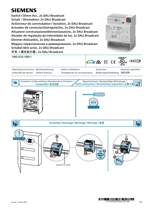
sOperating Instructions Betriebsanleitung Notice d'utilisationInstructivo Istruzioni operative Instruções de Serviço İşletme kılavuzu Руководство по эксплуатацииBedieningshandleiding 使用说明5WG1525-1DB11Switch / Dimm Act., 2x DALI Broadcast Schalt- / Dimmaktor, 2x DALI BroadcastActionneur de commutation / Variation, 2x DALI Broadcast Actuador de conmutación/regulación, 2x DALI BroadcastAttuatore commutazione/dimmerizzazione, 2x DALI Broadcast Atuador de regulação da intensidade da luz, 2x DALI Broadcast Dimmer Aktivatörü, 2x DALI BroadcastМодуль переключения и диммирования, 2x DALI Broadcast Schakel-/dim actor, 2x DALI Broadcast 开关-/ 调光执行器, 2x DALI BroadcastF0F4F5F6EN Illuminant defective DALI incorrect voltage DALI short circuit No ECG foundDE Leuchtmittel defekt Fremdspannung DALI Kurzschluss Kein EVG gefundenFR Lampe défectueuse Tension externe Court-circuit DALI Pas de ballast électronique trouvéES Fuente de luz defectuosa Tensión externa Cortocircuito DALI No se ha encontrado ningún balastoelectrónicoIT Lampada difettosa Tensione parassita Cortocircuito DALI Nessun reattore elettronico trovato PT Lâmpada com defeito Tensão externa Curto-circuito em DALI Nenhum balastro eletrónico encontrado TR Ampul bozuk Harici gerilim DALI kısa devre Elektronik balast bulunamadıРУНеисправен источник светаНапряжение от внешнегоКороткое замыкание DALIНе найден ЭПРАисточникаPL Lampa uszkodzona Napięcie zewnętrzne Zwarcie DALI Nie odnaleziono statecznika elektronicz-nego中灯具损坏外部电压 DALI 短路未找到 EVG© Siemens Schweiz AG 2019Subject to change without prior notice. Store for use at a later date."Technical Documentation:/gamma-tdTechnical Support/supportrequest)$4FAQ:https:///cs/ww/en/ps/faqListing and CertificationscUL listed (E464611)UL 916, Open Energy Management Equipment Electromagnetic compatibilityUSA:This device complies with part 15 of the FCC Rules. Operation is subject to the following two conditions:(1) This device may not cause harmful interference, and(2) this device must accept any interference received, including interference that may cause undesired operation.This equipment has been tested and found to comply with the limits for a Class B digital device, pursuant to part 15 of the FCC Rules. These limits are designed to provide reasonable protection against harmful interference in a residential installation. This equipment generates, uses and can radiate radio frequency energy and, if not installed and used in accordance with the instructions, may cause harmful interference to radio communications. However, there is no guarantee that interference will not occur in a particular installation. If this equipment does cause harmful interference to radio or television reception, which can be determined by turning the equipment off and on, the user is encouraged to try to correct the interference by one or more of the following measures:- Reorient or relocate the receiving antenna.- Increase the separation between the equipment and receiver.- Connect the equipment into an outlet on a circuit different from that to which the receiver is connected.- Consult the dealer or an experienced radio/TV technician for help.This device complies with Part 15 of the FCC rules. Changes or modifications not expressly approved by Siemens Schweiz AG could void the user’s authority to operate the equipment.United States representative:https:///us/en/products/buildingtechnologies/home.html Canada:CAN ICES-3(B)/NMB-3(B)(1) This equipment is intended for field installation within the enclosure of another product.WARNINGHazardous voltage.Can cause death, serious injury or property damage.The Device must not be opened.A faulty device should be returned to the local Siemens sales office or distributor.The device must be mounted and commissioned by a factory trained person.The prevailing safety rules must be observed!Mount in dry location only!。
西门子阀门与执行器匹配选型.
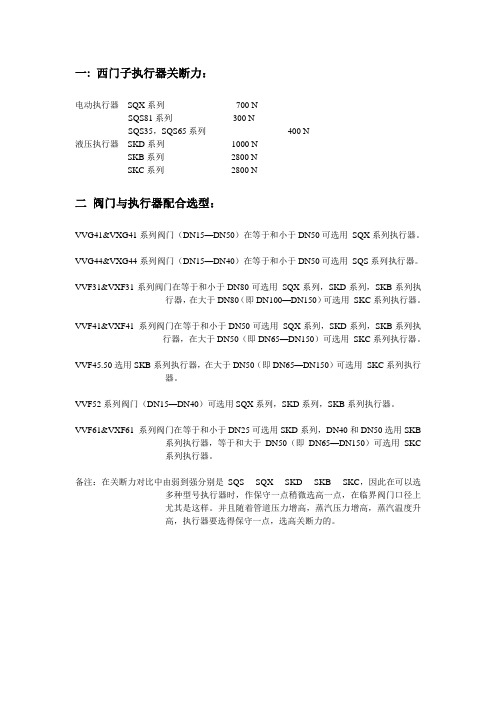
一: 西门子执行器关断力:电动执行器SQX系列-------------------- 700 NSQS81系列-------------------- 300 NSQS35,SQS65系列------------------------- 400 N液压执行器SKD系列-------------------- 1000 NSKB系列-------------------- 2800 NSKC系列-------------------- 2800 N二阀门与执行器配合选型:VVG41&VXG41系列阀门(DN15—DN50)在等于和小于DN50可选用SQX系列执行器。
VVG44&VXG44系列阀门(DN15—DN40)在等于和小于DN50可选用SQS系列执行器。
VVF31&VXF31系列阀门在等于和小于DN80可选用SQX系列,SKD系列,SKB系列执行器,在大于DN80(即DN100—DN150)可选用SKC系列执行器。
VVF41&VXF41 系列阀门在等于和小于DN50可选用SQX系列,SKD系列,SKB系列执行器,在大于DN50(即DN65—DN150)可选用SKC系列执行器。
VVF45.50选用SKB系列执行器,在大于DN50(即DN65—DN150)可选用SKC系列执行器。
VVF52系列阀门(DN15—DN40)可选用SQX系列,SKD系列,SKB系列执行器。
VVF61&VXF61 系列阀门在等于和小于DN25可选用SKD系列,DN40和DN50选用SKB系列执行器,等于和大于DN50(即DN65—DN150)可选用SKC系列执行器。
备注:在关断力对比中由弱到强分别是SQS----SQX----SKD----SKB----SKC,因此在可以选多种型号执行器时,作保守一点稍微选高一点,在临界阀门口径上尤其是这样。
并且随着管道压力增高,蒸汽压力增高,蒸汽温度升高,执行器要选得保守一点,选高关断力的。
- 1、下载文档前请自行甄别文档内容的完整性,平台不提供额外的编辑、内容补充、找答案等附加服务。
- 2、"仅部分预览"的文档,不可在线预览部分如存在完整性等问题,可反馈申请退款(可完整预览的文档不适用该条件!)。
- 3、如文档侵犯您的权益,请联系客服反馈,我们会尽快为您处理(人工客服工作时间:9:00-18:30)。
1.2
2
系统说明 ................................................................................................................................................. 2-1 2.1 2.2
7MF4□33 系列 SITRANS P - DS III 压力/差压变送器
DS III 系列变送器,差压系列包括差压、流量、液位和绝压测量,压力系列包括压力、绝压测量。 产品手册
目录
目录
1 技术说明 ................................................................................................................................................. 1-1 1.1 应用范围 ........................................................................................................................................1-1 1.1.1 压力 .................................................................................................................................1-2 1.1.2 差压和流量 ......................................................................................................................1-2 1.1.3 液位 .................................................................................................................................1-2 1.1.4 绝压 .................................................................................................................................1-2 设计和工作原理 .............................................................................................................................1-2 1.2.1 设计 .................................................................................................................................1-3 1.2.2 工作方式..........................................................................................................................1-5 1.2.2.1 电路原理 .........................................................................................................1-5 1.2.2.2 压力测量 .........................................................................................................1-6 1.2.2.3 差压和流量测量 ..............................................................................................1-6 1.2.2.4 液位测量 .........................................................................................................1-7 1.2.2.5 差压系列中的绝压测量 ...................................................................................1-7 1.2.2.6 压力系列中的绝压测量 ...................................................................................1-8 系统组成 ........................................................................................................................................2-1 SIMATIC PDM...............................................................................................................................2-2
3
现场操作和显示 ...................................................................................................................................... 3-1 3.1 操作总体说明 .................................................................................................................................3-1 3.1.1 数字显示..........................................................................................................................3-1 3.1.2 测量值代表含义 ...............................................................................................................3-2 3.1.3 单位显示/棒图 .................................................................................................................3-2 3.1.4 故障显示..........................................................................................................................3-3 3.1.5 信号范围..........................................................................................................................3-3 3.1.6 方式显示..........................................................................................................................3-4 3.2 键盘操作 ........................................................................................................................................3-4 3.2.1 取消键盘禁用和写保护 ....................................................................................................3-6 3.2.2 设定/调整零点和量程 ......................................................................................................3-6 3.2.2.1 相关原理 .........................................................................................................3-6 3.2.2.2 应用 ................................................................................................................3-9 3.2.3 电子阻尼........................................................................................................................3-10 3.2.4 无输入压力时零点和量程的设定 ...................................................................................3-10 3.2.4.1 相关原理 .......................................................................................................3-10 3.2.4.2 应用 ..............................................................................................................3-11 3.2.5 零点调整(物理位置校正)...........................................................................................3-11 3.2.6 电流模拟器 ....................................................................................................................3-12 3.2.7 故障电流........................................................................................................................3-12 3.2.8 键/功能禁用 ...................................................................................................................3-13