Truck Crane三一汽车吊PDF
北极熊工具1000磅手摇吊车吊车辆吊车说明书
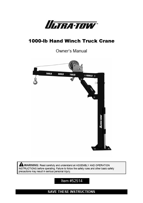
1000-lb Hand Winch Truck CraneOwner’s ManualWARNING: Read carefully and understand all ASSEMBLY AND OPERATION INSTRUCTIONS before operating. Failure to follow the safety rules and other basic safety precautions may result in serious personal injury.Item #52514Thank you very much for choosing an Ultra-Tow™ product!For future reference, please complete the owner’s record below:Serial Number/Lot Date Code: ________________________________ Purchase Date: ____________________________________________ Save the receipt, warranty, and this manual. It is important that you read the entire manual to become familiar with this product before you begin using it.This 1000-lb Hand Winch Truck Crane is designed for certain applications only. Northern Tool & Equipment is not responsible for issues arising from modification or improper use of this product such as an application for which it was not designed. We strongly recommend that this product not be modified and/or used for any application other than that for which it was designed.For technical questions, please call 1-800-222-5381.Intended Use (4)Technical Specifications (4)Important Safety Information (4)Specific Operation Warnings (5)Main Parts of Product (6)Assembly Instructions (6)Before Each Use (8)Operating Instructions (9)After Each Use (10)Maintenance (10)Troubleshooting (11)Parts Diagram (11)Parts List (12)Replacement Parts (12)Limited Warranty (13)The Ultra-Tow 1000-lb Hand Winch Truck Crane can easily lift loads onto the bed of your pickup. The crank-operated cable winch provides extra reach. The base swivels to easily access all sides of your truck or trailer bed. The crane folds away when not in use. This heavy-duty pickup truck crane is built for professional use.●●Assemble the post (02) to the base (01).●Attach the boom retracted (04) to the post (02).●Connect the long ram jack (12) with the boom retracted (04) to the post (02).●Insert the boom extension to the boom retracted.●Take off the cable from the winch then mount the winch (09) onto the boom retracted (04).●Cross the cable from the downside hole of the boom extension and to the upside hole.●Connect the cable to the winch and use the winch handle to wrap the cable onto the winch.How to install the cable on the hand winch:∙Loose hardware∙Misalignment or binding of moving parts∙Cracked or broken parts∙Proper ram operation∙Frayed, kinked or damaged cable∙Any other condition that may affect its safe operation1. To lift the crane, use the jack handle (21) to lock the jam valve, then put the handle into thefulcrum and lift the jam.2. To lower the crane, use the jack handle (21) to release the jam valve.Use Winch to Lift1. To wind the cable, push the lock pin to lock the winch and rotate the winch handle clockwise.2. To pull out all of the cable, unlock the winch.wheel well, and insert the post pin to prevent the boom from swiveling.∙It is recommended that the general condition of any tool be examined before it is used. Keep your crane in good repair by adopting a program of conscientious repair and maintenance inaccordance with the recommended procedures found in this manual. If any abnormal vibrations or noise occurs, stop using the crane immediately and have the problem corrected before further use. Have necessary repairs made by qualified service personnel.∙Use only soap and a damp cloth to clean your tools. Many household cleaners are harmful to plastics and other insulation. Never allow liquid to get inside of a tool.∙When servicing, use only identical replacement parts. Use of any other parts will void the warranty. Only use accessories intended for use with this crane.∙To add oil, fully collapse the jack and add oil to move the oil level to the oil plug. Use only hydraulic jack oil.∙Lubricate the grease fitting with a grease gun once a month, or when the boom becomes difficult to switch on the post.∙If the crane will be exposed to wet conditions, more frequent lubrication may be necessary to prevent build-up of rust.Use the table below to troubleshoot problems before contacting service personnel or your local dealer. If the problem continues after troubleshooting, call your local dealer for assistance.∙For replacement parts and technical questions, please call Customer Service at 1-800-222-5381. ∙Not all product components are available for replacement. The illustrations provided are a convenient reference to the location and position of parts in the assembly sequence.∙When ordering parts, the following information will be required: item description, item model number, item serial number/item lot date code, and the replacement part reference number.∙The distributor reserves the rights to make design changes and or improvements to product lines and manuals without notice.Northern Tool and Equipment Company, Inc. ("We'' or '"Us'') warrants to the original purchaser only ("You'' or “Your”) that the Ultra-Tow product purchased will be free from material defects in both materials and workmanship, normal wear and tear excepted, for a period of one year from date of purchase. The foregoing warranty is valid only if the installation and use of the product is strictly in accordance with product instructions. There are no other warranties, express or implied, including the warranty of merchantability or fitness for a particular purpose. If the product does not comply with this limited warranty, Your sole and exclusive remedy is that We will, at our sole option and within a commercially reasonable time, either replace the product or product component without charge to You or refund the purchase price (less shipping). This limited warranty is not transferable.Limitations on the WarrantyThis limited warranty does not cover: (a) normal wear and tear; (b) damage through abuse, neglect, misuse, or as a result of any accident or in any other manner; (c) damage from misapplication, overloading, or improper installation; (d) improper maintenance and repair; and (e) product alteration in any manner by anyone other than Us, with the sole exception of alterations made pursuant to product instructions and in a workmanlike manner.Obligations of PurchaserYou must retain Your product purchase receipt to verify date of purchase and that You are the original purchaser. To make a warranty claim, contact Us at 1-800-222-5381, identify the product by make and model number, and follow the claim instructions that will be provided. The product and the purchase receipt must be provided to Us in order to process Your warranty claim. Any returned product that is replaced or refunded by Us becomes our property. You will be responsible for return shipping costs or costs related to Your return visit to a retail store.Remedy LimitsProduct replacement or a refund of the purchase price is Your sole remedy under this limited warranty or any other warranty related to the product. We shall not be liable for: service or labor charges or damage to Your property incurred in removing or replacing the product; any damages, including, without limitation, damages to tangible personal property or personal injury, related to Your improper use, installation, or maintenance of the product or product component; or any indirect, incidental or consequential damages of any kind for any reason.Assumption of RiskYou acknowledge and agree that any use of the product for any purpose other than the specifieduse(s) stated in the product instructions is at Your own risk.Governing LawThis limited warranty gives You specific legal rights, and You also may have other rights which vary from state to state. Some states do not allow limitations or exclusions on implied warranties or incidental or consequential damages, so the above limitations may not apply to You. This limited warranty is governed by the laws of the State of Minnesota, without regard to rules pertaining to conflicts of law. The state courts located in Dakota County, Minnesota shall have exclusive jurisdiction for any disputes relating to this warranty.Distributed by:Northern Tool & Equipment Company, Inc.Burnsville, Minnesota 55306Made in China。
三一履带吊培训资料

二、SCC1000C履带起重机卖点分析 8、已通过通过欧盟CE认证及北美认证。
整机结构
二、SCC1000C履带起重机卖点分析
二、SCC1000C履带起重机卖点分析
整机结构 1、可配快速锁节式德国进口钢丝绳,安装方便,寿命更长; 2、履带架、配重具有自装卸功能; 3、折线卷筒设计能保证多层缠绕不乱绳; 4、非大圆弧司机室,视野更加开阔真实,操作更加人性化设计。
二、SCC1000C履带起重机卖点分析
液压系统
1、采用力士乐或川崎液压技术,系统稳定性、可靠性更高 ; 力士乐:负载敏感+负载独立流量分配系统(LUDV); 川崎:正流量+总功率控制系统; 2、具有卓越的回转和提升微动性能,负荷传感、极限负荷调节使操作更平 稳;
二、SCC1000C履带起重机卖点分析
性能特点
起重能力 微动性能 作业效率 适应性 配置 安全保护措施
二、SCC1000C履带起重机卖点分析
强大的起重能力
1、偏多功能机型设计,满足普通吊装、基础施工等作业; 2、最大起重力矩556.5t.m,最大额定起重量105t,同比最大; 3、提升卷扬可提供9.2t额定单绳拉力; 4、配置附加配重工况,在特定条件下,使用附加配重块可以增强中长臂 的起重能力 5、加强的主臂结构,起重能力及抗颤动能力更强。
二、SCC1000C履带起重机卖点分析
2、2009年7月100吨在大连(桩基施工)
大连大金马公司将100吨 改制为柴油桩锤专用机。 图示为主臂30米工况。
二、SCC1000C履带起重机卖点分析
3、浙江鼎业公司龙耀路越江隧道耀华皮尔金顿浮华玻璃码头拔桩工程(桩基施工)
浙江鼎业公司在100吨基础 上改装车。采用专利技术设备 FCEC内外正逆双回转拔桩机。
汽车起重机说明书【范本模板】

QY40汽车起重机液压系统设计摘要QY40型汽车起重机液压系统的设计是该型起重机设计过程中比较典型的一种.为了设计出符合汽车起重机性能要求的液压系统,主要做了以下四项工作。
第一,通过阅读大量国内外相关资料和调研市场上已存在产品,本文对QY40T型汽车起重机的功能和工作原理进行了深入的了解和分析;具体分析了汽车起重机液压系统的功能、组成、工作特点以及系统类型;总结出液压传动在汽车起重机应用中的优缺点。
第二,根据QY40T型汽车起重机的工作特点,确定了系统的起升回路、回转回路、变幅回路、伸缩回路和支腿回路的基本结构,并针对各单元回路的特点进行了具体的分析,进而对液压系统进行了整体设计.第三,根据汽车起重机的技术参数对液压系统进行了设计计算,并确定了液压系统元件;通过对系统压力损失的验算和发热校核,检验液压系统设计的合理性。
第四,根据汽车起重机的工作特点,确定了液压装置的形式,并进行了集成块的设计。
在设计过程中,本文参考一些同类产品的液压系统设计。
结合工程实际,最终设计出了功能完善、性能良好,适合我国生产制造的汽车起重机液压系统。
关键词:汽车起重机,液压系统,性能参数,集成块THE DESIGN OF QY40 TYPE AUTOMOBILECRANE HYDRAULIC SYSTEMABSTRACTThe design of the QY40 type automobile crane hydraulic system is the typical crane designing process.In order to scheme out the hydraulic system that meets the performance requirements of automobile crane, this article mainly do the following four tasks. First,through reading a large number of domestic and foreign information and researching about existing products on the market, this article makes in—depth understanding and analysis of the functions and working principle of the QY40 type automobile crane; having concretely analyzed the automobile crane hydraulic system of its function,composition, work characteristics and the type of system; summarized the advantages and disadvantages of hydraulic transmission in automobile crane applications。
三一250吨履带吊说明书SCC2500C
kW rpm
t
mm MPa
参数
260 1442 16.5~91.5 30°~81° 76.5+31 10°,30° (37.5~76.5)+7 19.5+7 30° 71.4 61.5+61 63°~88° 0~143 (0~31)×2 0~34 0~1.8 0~1.04/0~0.51(双速) 30% 242 2100
×2 6.14m 2.34m 2.4m 1.7 t
×5 12.14m 2.34m 2.4m 2.9 t
5
SCC2500C 液压履带起重机
塔况组合 长 宽 高 重量
变幅副臂上节臂 长 宽 高 重量
变幅副臂 3m 中间臂 长 宽 高 重量
变幅副臂 6m 中间臂 长 宽 高 重量
变幅副臂 12m 中间臂 长 宽 高 重量
×12 1.96m 1.33m 0.42m
6t
×2 1.75m 1.44m 0.97m 12.4 t
7
SCC2500C 液压履带起重机
250t 吊钩 长 宽 高 重量
150t 吊钩 长 宽 高 重量
100t 吊钩 (选配) 长 宽 高 重量
80t 吊钩 长 宽 高 重量
35t 吊钩 长 宽 高 重量
×1 2.81m 0.29m 0.8m 0.3 t
×1 5.18m 1.01m 1.5m 0.7 t
6
SCC2500C 液压履带起重机
固定副臂上节臂 长 宽 高 重量
固定副臂 3m 中间臂 长 宽 高 重量 固定副臂 6m 中间臂 长 宽 高 重量
过渡节 长 宽 高 重量
托盘配重块 长 宽 高 重量
三一30吨伸缩臂工况表
三一30吨伸缩臂工况表
随着国家对工程建设的不断推进,施工机械的需求也在逐步增加,其中伸缩臂起重机的应用越来越广泛。
三一30吨伸缩臂工况表是目前市面上常用的一种工具,它可以帮助施工人员更好地了解该型号伸缩臂起重机的使用条件和限制,从而提高施工效率和安全性。
三一30吨伸缩臂工况表对该型号起重机的性能参数进行了详细的说明。
例如,该起重机的最大起重量为30吨,最大起升高度为43.5米,最大作业半径为33米等等。
这些参数可以帮助施工人员更好地了解起重机的使用范围和限制,从而选择合适的工作条件和操作方式,避免在施工过程中出现安全事故。
三一30吨伸缩臂工况表还对该型号起重机的工作环境进行了详细的描述。
例如,该起重机适用于室内和室外的多种场合,但需要保证工作场地平坦、坚实和稳定,避免出现倾斜或不平的情况。
此外,起重机的工作环境还需要保持通风良好,避免出现有害气体或粉尘对操作人员的危害。
除此之外,三一30吨伸缩臂工况表还对该型号起重机的操作方式和注意事项进行了详细的说明。
例如,在起重机的操作过程中需要注意起重机的负载情况,避免超载或不平衡的情况。
此外,起重机的工作台需要保持干净整洁,避免出现杂物或障碍物对操作人员的危害。
三一30吨伸缩臂工况表是施工人员在使用该型号伸缩臂起重机时必备的工具之一。
通过该工况表的使用,施工人员可以更好地了解起重机的性能参数、工作环境、操作方式和注意事项等关键信息,从而更好地保障施工安全和效率。
电子课件-《工程机械(汽车起重机)操作与维护》-A07-3033 模块一 汽车起重机认知
课题2 汽车起重机液压系统认知
一、汽车起重机底盘液压系统 1. 底盘液压系统工作原理
支腿液压系统工作原理图
17 模块一 汽车起重机认知
2. 液压油箱总成 3. 液压油泵 4. 下车多路阀 5. 水平油缸 6. 垂直油缸 7. 双向液压锁 8. 中心回转体
18 模块一 汽车起重机认知
二、全地面起重机底盘悬挂液压系统
3 模块一 汽车起重机认知
二、国内汽车起重机生产厂家介绍 1. 徐州重型机械有限公司 2. 长沙中联重工科技发展股份有限公司浦沅分公司 3. 三一汽车起重机械有限公司
4 模块一 汽车起重机认知
三、国内外汽车起重机的发展趋势 1. 广泛采用新技术 2. 重视技术融合,向机电液一体化方向发展 3. 通用机型以中小型为主,专用机型向大型化发展 4. 发展越野及全地面起重机
13 模块一 汽车起重机认知
子课题3 国内外汽车起重机的发展概况
一、汽车起重机的整体构造
14 模块一 汽车起重机认知
二、汽车起重机底盘的结构组成
15 模块一 汽车起重机认知
三、汽车起重机工作装置的结构组成 1. 起升机构 2. 回转机构 3. 伸缩机构 (1)主臂机构 (2)副臂机构 4. 变幅机构
21 模块一 汽车起重机认知
5. 力矩限制器系统 (1)力矩限制器系统的组成 全自动力矩限制器系统主要由 主机—中心控制器、CAN 接线盒、 彩色液晶图形显示器、油压传感器、 长度/角度传感器、高度限位开关 及重锤等组成。
力矩限制器系统结构
22 模块一 汽车起重机认知
(2)力矩限制器系统的工作原理 力矩限制器系统按实际力矩与额定力矩比较的原则进行控 制。微处理器根据各传感器输入的吊臂长度、角度信号,计算 出起重机的作业半径。根据压力传感器输入的信号计算出变幅 油缸的受力,然后算出起重力矩。根据力传感器测量得出的实 际值在微处理器中与存储在中心控制器存储器中的额定值进行 比较,达到极限时,在显示器上发出过载报警信号,同时,主 机输出控制信号,结合起重机的外围控制元件,起重机的危险
三一起重机QY50C技术协议
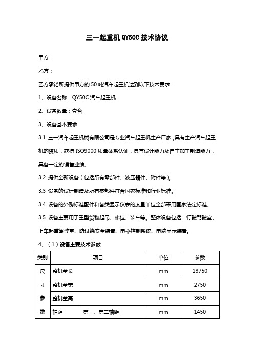
三一起重机QY50C技术协议甲方:乙方:乙方承诺所提供甲方的50吨汽车起重机达到以下技术要求:1、设备名称:QY50C汽车起重机2、设备数量:壹台3、设备基本要求3.1 三一汽车起重机械有限公司是专业汽车起重机生产厂家,具有生产汽车起重机的资质,获得ISO9000质量体系认证,具有设计能力及自主加工制造能力,具备一定的销售业绩。
3.2 提供全新设备(包括所有零部件、液压器件、附件等)。
3.3 设备的设计制造及所有零部件符合国家标准和行业标准。
3.4 设备的外购标准配件和各类显示仪表的度量单位全部采用国家法定标准。
3.5 设备主要用于重型货物起吊、移位、装车等。
整体设备包括:行驶驾驶室、上车起重驾驶室、防过绕安全装置、电器控制系统、电脑显示装置。
4、(1)设备主要技术参数(2)主要技术特点1)超长吊臂,超强起吊能力采用六边形大圆弧截面高强度结构钢起重臂,主臂全伸长42.5米,主臂+副臂长58.5米,最大起吊高度58.8m,最大起重力矩达1788.5KN.m,行业领先。
2)卓越的行驶通过能力,创新让作业更安全最高行驶速度超过76km/h,最大爬坡度35%;采用德国ZF转向技术,美国EATON公司变速箱技术,操纵轻便,可靠。
采用先进工程机械控制系统,全面的吊重力矩保护、高度限位与报警功能,为作业提供可靠的安全保护。
3)高效液压系统,实现远程监控进口柱塞泵,变量液压系统,可根据负载自动进行流量控制;主、副卷扬采用进口变量马达,轻载起吊速度快,单绳最大速度达130m/min,作业效率高,节能效果好;通过“GCP全球客户门户网”,可实施远程工况监控和远程设备管理;您可以足不出户掌握设备的运行状况、查询和订购所需配件。
4)顶级配置,集国际品牌于一身液压泵、马达、阀等主要液压元件采用日本川崎、Rexroth等国际知名品牌。
丹麦DANFOSS压阻式压力传感器和德国SCHMERSAL高度限位器。
德国HELLA 继电器、WAGO接插件和美国COOBER公司中央配电盒。
汽车起重机 QYE12 1 数据表 (公制) 说明书
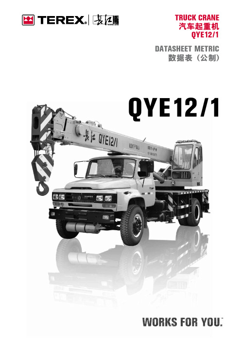
QYE12/1TRUCK CRANE 汽车起重机QYE12/1DATASHEET METRIC数据表 (公制)QYE12/12Page · 页码:Key · 关键词汇.......................................................................................................3Dimensions and Specifications · 技术参数Crane Dimensions . 起重机外形尺寸......................................................................4Specifications . 规格参数................................................................................5Range Diagram . 起升高度. (6)Load Charts · 起重量表......................................................................................................7Technical Descriptions · 技术描述Lifting Capacity . 起重量 (8)Boom and Components · 主臂和零件.................................................................. 8Jib · 副臂............................................................................................ 8Winch Performance · 起升机构工作速度................................................................ 9Crane Boom Function Speeds · 起重臂工作速度........................................................ 9Outrigger Function Speeds · 支腿工作速度............................................................. 9Outrigger Controls · 支腿操纵......................................................................... 9Engine and Transmission · 发动机和变速箱............................................................ 10Hydraulics · 液压系统................................................................................. 10Chassis and Components · 底盘及其部件.............................................................. 11Driver Cab · 驾驶室................................................................................... 11Operator Cab · 操纵室................................................................................11CONTENTS · 目录QYE12/13KEY · 关键词汇QYE12/14CRANE DIMENSIONS 起重机外形尺寸QYE12/15SPECIFICATIONS 规格参数QYE12/16RANGE DIAGRAM 起升高度Notes · 说明The tabulated rated loads include weight of hook and slings, main hook is 130 kg.The values in table are rated lifting capacities of crane on solid ground and in leveling state. The working radius in the table is actual radius when load is lifted.The values above the bold line are based on crane strength, those below the bold line are based on crane stability.If the boom length exceeds the specified values, comparing it’s capacities with the next longer one’s, the load to be lifted should be the smaller one’s.Telescoping boom with load is not allowed.表中额定起重量包括吊钩和吊具的重量,主钩重.130 kg 。
三一汽车起重机电气系统培训课件

系统压力开关是为了防止进出上车操纵室误碰操纵手柄而出现 误动作而设置的;在作业之前必须接通此开关,系统建立压力方 能进行操作,离开操纵室后应及时关闭此开关。
14
15
16
17
18
可选装配件
1、三色报警灯
装在操纵室前部,用来提示操纵室外部人员目前 吊载的情况; 绿灯表示正常吊载,力矩百分比小于90% 黄灯表示即将超载,力矩百份比在90%~105%之间 红灯表示已经超载,力矩百分比超过105%
自主设计的定位功能,可极大提高开关的使用寿命,拥有专利技术。
7
8
4、三圈保护器GL-190
当起重机全伸臂、小幅度吊钩落地时,卷扬钢丝绳有可能过放。钢丝 绳在卷筒上剩余至少三圈时,保护器动作,同时过放信号使卷扬下降电磁阀 卸荷,吊钩下降的运动被切断,落钩工况自动停止,过放报警灯点亮。
安装照片
9
内部照片
3 长度/角度传感器QZK-60
7 防过卷开关(德国施迈赛)
4 导电环总成GL-4-13A/17A
8 示廓灯、臂顶灯、工作灯
4
1、力限器主机SYMC运动控制器
※国内第一款通用运动控制器 ※针对三一具体情况量身定做 ※超过90个独立IO点 ※高可靠性、高防护等级 ※ IEC61131-3标准开发环境 ※丰富的通信接口 (CAN2.0B、RS422/RS484RS232) ※输出5V传感器电源 ※左右对称结构,可靠性高。 ※ SYMC控制器在逻辑上与普通PLC(可编程逻辑 控制器)没有本质区别,可以使IEC61131-3标准 开发环境编程、调试。支持梯形图、指令表等五 种标准开发语言。
度
传 特 拉线有效长度53米,收线时 拉线有效长度40米,不能自 拉线有效长度40米,内卷式,易
三一汽车起重机液压知识培训营销适用200908191PPT课件

产品特色——独特的回转缓冲设计 回转机构采用两级缓冲,能在较大的范围吸收回转冲击,从而使回转平 稳制动柔和。
该缓冲阀全部采用进 口元件,性能可靠。
第52页/共60页
产品特色——合理的系统配置
QY25CS(手动型) 作业安全 系统简单 价格实惠
QY25CY(液控型) 高可靠性 更优越
第53页/共60页
上车液压系统
第13页/共60页
组成结构及原理
3.1、下车液压系统
第14页/共60页
组成结构及原理
下车液压系统
卷扬 变幅 伸缩
第15页/共60页
组成结构及原理
第16页/共60页
油泵
第17页/共60页
油箱
第18页/共60页
支腿
第19页/共60页
QY25CS组成结构及原理
支腿
液压锁
第20页/共60页
第47页/共60页
QY50CS组成结构及原理
25C比例定量系统 50C负载反馈比例变量系统
第48页/共60页
产品特色
4、产品特色介绍
第49页/共60页
产品特色——强劲的起重能力
QY25C
行业第一
最 大 起 重 力 矩 986kN·m
QY50C
最 大 起 重 力 矩 1788kN·m
第50页/共60页
第55页/共60页
自制阀组
第56页/共60页
生产过程品质保证
第57页/共60页
第58页/共60页
疾慢如仇、追求卓越的企业文化注定了 我们一定会发展的更快,做的更好。一切为 了客户的经营理念决定了我们一定会为客户 送上最高品质的产品。
谢 谢!
第59页/共60页
SRC550H越野起重机-三一重工

轴载荷
前轴
后轴
22500 22200
kg
kg
总重
44700 kg
SRC550H 越野起重机/55公吨起重量
SRC550H• ROUGH-TERRAIN• CRANE 55• METRIC• TONS• CAPACITY
PAGE
02
技术参数 尺寸 技术参数
技术描述 底盘 上车
主臂 工作范围 起重能力
副臂 工作范围 起重能力
PAGE
08
SRC550H越野轮胎起重机主要技术参数
类别 项目
参数
单位
整机全长 尺
整机全宽 寸
整机全高
参 轴距
数 轮距
14000 mm
3300
mm
3760
mm
4000
mm
2502
mm
最高行驶速度
40
km/h
最小转弯半径(2轮/4轮)
12.3/6.7 m
最小离地间隙 行
接近角 驶 离去角 参 制动距离(20km/h) 数 最大爬坡度
最长主臂 数
支腿跨距(横向×纵向)
987/1500 N.m/rpm
Tier 3
55
t
3
m
1789
kN.m
841
kN.m
7.2×7.2 m
基本臂
13.3
m
起升高度
最长主臂
43.8
m
最长主臂+副臂 60.1
m
基本臂
11.5
m
起重臂长度
最长主臂
42.5
m
最长主臂+副臂 58.5
m
副臂安装角
0\15\30 °
三一汽车吊车操作安全培训教材
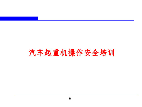
操作要点
起升机构动作不可过急 21
③ 副起升操作方法 推杆控制:操作副卷扬操纵杆前推,起重钩下落 、后拉起重钩上升;起落速度由操纵杆和油门来 调节。 先导控制:按下主令开关S9和伸缩/副卷扬转换 开关S13,将左控制手柄前推,副起重钩下落、后 拉副起重钩上升;起落速度由左控制手柄和油门 来调节。
操作要点
副卷扬操纵杆
22
(5)主起重臂伸缩 ①操作要点:
a 液压油温升不能过高 b 主起重臂发生自然回缩时,可适当进行 伸缩操作来调整所需长度 c 不允许带载伸缩 ② 伸缩操纵方法: 推杆式操作:将伸缩操纵杆向前推,主起 重臂伸出,向后拉则主起重臂缩回,速度由 操纵杆和油门来调节。 先导式操作:按下主令开关S9,将操纵手 柄向前推,主起重臂伸出,向后拉则主起重 臂缩回,速度由操作手柄和油门来调节。
操作要点
27
三:操作注意事项(P35-P48)
28
(一)停车注意事项 1、松开脚油门,踩下脚制动踏板制动,待车停稳 后,将停车制动操纵手柄向后扳动直至锁定。 2、将变速器切换到空档位置。 3、熄火前空加油2~3次,使各部分得到充分润滑 ,再关闭钥匙开关,使发动机熄火。 4、将电源总开关关掉,以防蓄电池放电。
汽车起重机操作安全培训
0
最大额定起重量: 工作幅度:
1
目
录
一、启动前准备工作 二、操作要点 三、操作注意事项
2
启动前准备工作
1、检查轮胎气压,轮胎是否有损坏; 2、围绕车检查一圈,检查是否有渗漏现象; 3、检查发动机的冷却水,机油和燃油是否充足; 4、排除储气筒内的积水; 5、检查蓄电池接线桩是否牢固可靠,电解液液面高度是否符合规定;
3
(一)作业环境要求 1、工作场地允许风速小于7级; 2、允许使用的环境温度 : -20 ℃ ~+40 ℃; 3、支承地面应坚实,支承地面抗压强 度≥3Mpa,作业过程中支承地面不得 下陷; 4、工作时,整车倾斜度不大于1%; 5、作业状态下应保证轮胎离地。
Link-Belt Cranes 90 吨(80.0 公吨)大型地面坦途吊车数据规格与负载能力说明书
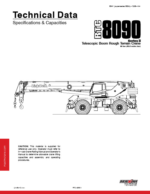
15541(supersedes5524)---1208---N4 Technical DataSpecifications&CapacitiesT elescopic Boom Rough T errain Crane90ton(80.0metric ton)CAUTION:This material is supplied forreference use only.Operator must refer toin---cab Crane Rating Manual and Operator’sManual to determine allowable crane liftingcapacities and assembly and operatingprocedures.5541(supersedes5524)---1208---N45541(supersedes5524)---1208---N4Table Of Contents....................................................Boom,Attachments,and Upper Structure1 ....................................................................................Boom1 Boom Wear Pads1 ......................................................................................................................................................Boom Head1 ..........................................................................Boom Elevation1.........................................................Auxiliary Lifting Sheave---Optional1..........................................................Hook Blocks and Balls---Optional1 ...........................................................................Fly---Optional1.................................................................Fly Extensions---Optional1................................................................ Operator’s Cab and Controls1 ....................................................................................Swing2 ................................................................................. Electrical2 .........................................................................Load Hoist System3...................................................................Load Hoist Performance3....................................................2M Main and Optional Auxiliary Winches3 .......................................................................... Hydraulic System3 ............................................................................ Counterweight3Carrier4 .......................................................................................................................................................................General4 ................................................................................ Outriggers4 .........................................................................Steering and Axles4 ............................................................................... Suspension4 ..........................................................................Tires and Wheels4 ...................................................................................Brakes4 ................................................................................. Electrical4...................................................................................Engine4 .............................................................................. Transmission4.............................................................Carrier Speeds and Gradeability5 .................................................................................Fuel Tank5 .......................................................................... Hydraulic System5...............................................................................Pump Drive5 ................................................................................Axle Loads6 ........................................................................General Dimensions7....................................................................Working Range Diagram8 Boom Extend Modes9 .......................................................................Main Boom Lift Capacity Charts--Standard10............................................................................19,200lb Counterweight---Fully Extended Outriggers---360 Rotation10 19,200lb Counterweight---On Tires---Stationary---Boom Centered Over Front Between Tire Tracks11.........19,200lb Counterweight---On Tires---Pick&Carry(Creep)---Boom Centered Over Front12 19,200lb Counterweight---On Tires---Stationary---360 Rotation12.........................................................28,800lb Counterweight---Fully Extended Outriggers---360 Rotation135541(supersedes5524)---1208---N4...............................................Fly Attachment Lift Capacity Charts--Optional14...........................19,200lb Counterweight---Fully Extended Outriggers---360 Rotation14....................................................140ft Main Boom Length---2 Fly Offset14...................................................140ft Main Boom Length---15 Fly Offset14...................................................140ft Main Boom Length---30 Fly Offset15 140ft Main Boom Length---45 Fly Offset15..............................................................................28,800lb Counterweight---Fully Extended Outriggers---360 Rotation16 140ft Main Boom Length---2 Fly Offset16.......................................................................................................140ft Main Boom Length---15 Fly Offset16...................................................140ft Main Boom Length---30 Fly Offset17...................................................140ft Main Boom Length---45 Fly Offset17....................................................Main Boom Lift Capacity Charts--Metric18............................8710kg Counterweight---Fully Extended Outriggers---360 Rotation18.8710kg Counterweight---On Tires---Stationary---Boom Centered Over Front Between Tire Tracks19..........8710kg Counterweight---On Tires---Pick&Carry(Creep)---Boom Centered Over Front20...............................8710kg Counterweight---On Tires---Stationary---360 Rotation20.......................... 13065kg Counterweight---Fully Extended Outriggers---360 Rotation21...............................................Fly Attachment Lift Capacity Charts--Optional22............................8710kg Counterweight---Fully Extended Outriggers---360 Rotation22..................................................42.67m Main Boom Length---2 Fly Offset22.................................................42.67m Main Boom Length---15 Fly Offset22.................................................42.67m Main Boom Length---30 Fly Offset23.................................................42.67m Main Boom Length---45 Fly Offset23 13065kg Counterweight---Fully Extended Outriggers---360 Rotation24............................................................................42.67m Main Boom Length---2 Fly Offset2442.67m Main Boom Length---15 Fly Offset24..................................................................................................42.67m Main Boom Length---30 Fly Offset25.................................................42.67m Main Boom Length---45 Fly Offset251 5541(supersedes5524)---1208---N4Boom,Attachments,and Upper StructureJ BoomDesign---Five section,formed construction of extra high tensile steel consisting of one base section and four tele-scoping sections.The two plate design of each section has multiple longitudinal bends for superior strength.Each telescoping section extends independently by means of one double---acting,single stage hydraulic cylinder with integrated holding valves.BoomS38---140ft(11.6---42.7m)five section boomS Three boom extend modes(EM1through EM3),con-trolled from the operator’s cab,provide superior capaci-ties by varying the extension of the telescoping sections: S EM1extends to140.0ft(42.7m)S EM2extends to115.8ft(35.3m)S EM3extends to76.5ft(23.3m)S Mechanical boom angle indicatorS Maximum tip height for each extend mode is:S EM1is149ft7in(45.6m)S EM2is125ft9in(38.3m)S EM3is87ft1in(26.5m)Boom Wear PadsS Wear pads with T eflon inserts that self---lubricate the boom sectionsS Bottom wear pads are universal for all boom sectionsS T op wear pads are universal for all boom sections Boom HeadS Five16.5in(41.9cm)root diameter nylon sheaves to han-dle up to ten parts of lineS Easily removable wire rope guardsS Rope dead end lugs on each side of the boom headS Boom head is designed for quick---reeve of the hook blockBoom ElevationS One double acting hydraulic cylinder with integral hold-ing valveS Boom elevation:---3 to80Auxiliary Lifting Sheave---OptionalS Single16.5in(41.9m)root diameter nylon sheaveS Easily removable wire rope guardsS Does not affect erection of the fly or use of the main head sheavesHook Blocks and Balls---OptionalS40ton(36.3mt)4sheave quick---reeve hook block with safety latchS60ton(54.4mt)4sheave quick---reeve hook block with safety latchS80ton(72.5mt)5sheave quick---reeve hook block with safety latch S90ton(80.0mt)6sheave quick---reeve hook block with safety latchS8.5ton(7.7mt)swivel and non---swivel hook balls with safety latchS10ton(9.1mt)swivel and non---swivel hook balls with safety latchFly---OptionalS35ft(10.7m)one piece lattice fly,stowable,offsettable to 2 ,15 ,30 ,and45 .Maximum tip height is184ft2in (56.1m).S35ft---58ft(10.7---17.7m)two piece bi---fold lattice fly, stowable,offsettable to2 ,15 ,30 ,and45 .Maximum tip height is206ft8in(63.0m).Fly Extensions---OptionalS One16ft(4.9m)lattice extension,equipped with two16.5 in(41.9cm)root diameter nylon sheaves,to be mounted between the boom head and fly options.Maximum tip height is222ft4in(67.8m).S T wo16ft(4.9m)lattice extensions,one equipped with two 16.5in(41.9cm)root diameter nylon sheaves,to be mounted between the boom head and fly options.Maxi-mum tip height is238ft2in(72.6m).Minimum of19,200lb (8700kg)of counterweight required.J Operator’s Cab and Controls Environmental Cab---Fully enclosed,one person cab of galvaneal steel structure with acoustical insulation Equipped with:S Tinted and tempered glass windowsS Extra---large fixed front window with windshield wiper and washerS Swing up roof window with windshield wiperS Sliding left side door with large fixed windowS Sliding rear and right side windows for ventilationS Six way adjustable,cushioned seat with seat belt and storage compartmentS Diesel fired warm---water heater with air ducts for front windshield defroster and cab floorS Defroster fan for the front windowS Bubble levelS Circulating fanS Adjustable sun visorS Dome lightS Cup holderS Fire extinguisherS Left side viewing mirrorS Two position travel swing lockAir Conditioning---Optional---Integral with cab heating system utilizing the same ventilation outletsEngine Dependant Warm---Water Heater---Optional---With air ducts for front windshield defroster and cab floor25541(supersedes5524)---1208---N4Steering Column---Pedestal type with tilt and telescope functions for operator comfort.Column includes the follow-ing controls and indicators:Left and right levers include:S Horn buttonS Turn signal switchS Driving light switchS Transmission direction switchPanel mounted switches for:S Travel park brakeS Steer mode selectorS2/4wheel drive/range selectorS Transmission gear selectorS Hazard flasherPanel mounted indicator/warning lights for:S Transmission temperatureS Engine oil pressureS Travel park brakeS Service brakeS Turn signalsS Rear wheel offsetS Emergency steer---optionalArmrest Controls---Two dual axis hydraulic joystick con-trollers or optional single axis hydraulic controllers for:S SwingS Boom hoistS Main rear winchS Auxiliary front winch---optionalS Drum rotation indicationS Drum rotation indicator activation switchS Winch high/low speed and disable switch(es)S Warning horn buttonS Swing park brakeOutrigger Controls---Hand held control box with umbilical cord gives the operator the freedom to view operation while setting the outriggers.Foot ControlsS Boom telescopeS Swing brakeS Engine throttleS Service brakeRight Front Console---Controls and indicators for:S Engine ignition S Console dimmer switchS Engine throttle lock S Bubble levelS Function disable S12volt power connectionS Front windshield wiper S Air conditioning---optional and washer S Boom floodlight---optional S Cab floodlights S Rotating beacon/StrobeS Warning horn light---optionalS Heating controls S Third wrap indicator---optionalCab Instrumentation---Ergonomically positioned,analog instrumentation for crane operation including:S Engine coolant temperature with warning indicatorS Hydraulic oil temperature with warning indicatorS Fuel level with warning indicatorS T achometerS Transmission temperature with warning indicatorS Voltmeter with warning indicator Rated Capacity Limiter---Microguard graphic audio---visual warning system integrated into the dash with anti---two block and function limiter.Operating data available includes:S Crane configurationS Boom length and angleS Boom head heightS Allowed load and%of allowed loadS Boom angleS Radius of loadS Actual loadS Operator settable alarms(include):S Maximum and minimum boom anglesS Maximum tip heightS Maximum boom lengthS Swing left/right positionsS Operator defined area(imaginary plane)Integrated Third Wrap Indicator---Optional---Micro-guard color display visually and audibly warns the operator when the wire rope is on the first/bottom layer and when the wire rope is down to the last three wraps.Internal RCL Light Bar---Optional---Visually informs the operator when crane is approaching maximum load capac-ity with a series of green,yellow,and red lights.External RCL Light Bar---Optional---Visually informs the ground crew when crane is approaching maximum load capacity with a series of green,yellow,and red lights.J SwingMotor/Planetary---Bi---directional hydraulic swing motor mounted to a planetary reducer for360 continuous smooth swing at1.9rpmSwing Park Brake---360 ,electric over hydraulic,(spring applied/hydraulic released)multi---disc brake mounted on the speed reducer.Operated by a switch from the opera-tor’s cab.Swing Brake---360 ,foot operated,hydraulic applied disc brake mounted to the speed reducerSwing Lock---Two---position swing lock(boom over front or rear)operated from the operator’s cab360 Positive Swing Lock---Optional---Meets New York City requirementJ ElectricalSwing Alarm---Audio warning device signals when the upper is swinging.LightsS Two working lights on front of the cabS One rotating amber beacon on top of the cab---optional S One amber strobe beacon on top of the cab---optional S Boom floodlight---optional3 5541(supersedes5524)---1208---N4J Load Hoist SystemLoad Hoist Performance116,8807656.617252.4341104.011434.711434.7 215,5197039.318757.0371113.112437.823872.5 314,3626514.520261.6401122.213440.8372113.4 413,3656062.321766.1430131.114443.9516157.3 512,4975668.523270.7460140.215446.9670204.2 6------------------------------------------------------16450.0834254.2Main(Rear)Winch Standard3/41918x19rotation resistant---right regular lay(Type RB)12,9205860.5 Optional3/4194strand,low torque,right regular lay(Type GC)22,40010160.5 Optional3/41934x7rotation resistant---right regular lay(Type ZB)15,6007076.2Auxiliary(Front)Winch Standard3/41918x19rotation resistant---right regular lay(Type RB)12,9205860.5 Optional3/4194strand,low torque,right regular lay(Type GC)22,40010160.5 Optional3/41934x7rotation resistant---right regular lay(Type ZB)15,6007076.22M Main and Optional Auxiliary WinchesS Axial piston,full and half displacement(2---speed)motors driven through planetary reduction unit for positive con-trol under all load conditions.S Grooved laggingS Power up/down mode of operationS Hoist drum cable follower---optionalS Drum rotation indicatorS Drum diameter:16in(40.6cm)S Rope length:S Main:730ft(222.5m)S Auxiliary:500ft(152.4m)or730ft(222.5m)S Maximum rope storage:834ft(254.2m)S T erminator style socket and wedgeThird wrap indicator---optional---Visually and audibly warns the operator when the wire rope is on the first/bottom layer and when the wire rope is down to the last three wrapsJ Hydraulic SystemCounterbalance Valves---All hoist motors,boom extend cylinders,and boom hoist cylinders are equipped with counterbalance valves to provide load lowering and pre-vents accidental load drop when hydraulic power is sud-denly reduced.Hydraulic Oil Coolers---Two carrier mounted coolers re-move heat from the hydraulic oil.One is integral to the en-gine radiator/charge air cooler and the other is mounted on left side of the carrier.J CounterweightStandard---T otal of19,200lb(8709.0kg)counterweight consisting of two counterweights pinned to the upper with capacities for:S0lb(0kg)counterweight*S9,600lb(4354.5kg)counterweightS19,200lb(8709.0kg)counterweightOptional---9,600lb(4354.5kg)in addition to standard counterweight for a total of28,800lb(13063.0kg)coun-terweight with capacities for:S0lb(0kg)counterweight*S9,600lb(4354.5kg)counterweightS19,200lb(8709.0kg)counterweightS28,800lb(13063.0kg)counterweight**Travel speed limited to5mph.Optional---Hydraulic counterweight removal activated by a hand---held controller with enough cable to access the pins on each side of the counterweights.45541(supersedes5524)---1208---N4CarrierJ GeneralS10ft9in(3.28m)wideS14ft4in(4.37m)wheelbase(centerline of first axle to centerline of second axle)Frame---Box---type,torsion resistant,welded construction made of high tensile steel.Equipped with front and rear towing and tie---down lugs,tow connections,and access ladders.J OutriggersBoxes---Two double box,front and rear welded to carrier frameBeams and Jacks---Four single stage beams with Con-fined Area Lifting Capacities(CALC t)provide selectable outrigger extensions of full,intermediate,and retracted. Hydraulically controlled from the operator’s cab with inte-gral check valves.Pontoons---Four lightweight,quick release,23.5x23.5in (59.7x59.7cm),steel pontoons with contact area of460in2 (2968cm2)can be stored for road travel in storage racks on the carrier.Main Jack Reaction---108,000lb(48988kg)force and 235psi(1620kPa)ground bearing pressureJ Steering and AxlesSteering---Four independent modes consisting of two wheel front,two wheel rear,four wheel,and crab.Each mode is controlled from the steering wheel and is selected by a switch in the operator’s cab.Drive---Two modes:4x2and4x4for off highway travel Axle1---Steered,non---driven for4x2and steered,driven for4x4Axle2---Steered,drivenJ SuspensionFront---Rigid mount to the carrier frameRear---The rear axle is suspended on the oscillation cylin-ders with motion of the axle controlled by a four bar linkage system.The oscillation cylinders lockout when the upper structure rotates2.5 past centerline.S Hydro---gas rear suspension---optionalRide Height Adjustment---Suspension can be lowered for transport using a hand---held controller from level ground.J Tires and WheelsFront and Rear---Four(single)29.5x25---28ply rating, earthmover type tires on steel disc wheelsS Spare tires and wheels---optionalJ BrakesService---Full hydraulic,dual circuit,disc type brakes on all wheel endsParking/Emergency---Spring applied type,acting on front axleJ ElectricalTwo batteries provide12volt starting and operation LightsS Front lighting includes two main headlights and two park-ing/directional indicators.S Side lighting includes two parking/directional indicators per side.S Rear lighting includes two parking/directional indicators, two parking/brake lights,and two reversing lights.S Other equipment includes hazard/warning system,cab light,instrument panel light,and signal horn.J EngineNumbers of Cylinders6Cycle4Bore and Stroke:inch(mm) 4.13x5.00(105x127) Piston Displacement:in3(L)402.7(6.6)Max.Brake Horsepower:hp(kW)235(175.2)@2,000rpm225(167.8)@2,200rpm Peak Torque:ft lb(Nm)724(981.7)@1,500rpm Alternator:volts---amps12---150 Crankcase Capacity:qt(L)18.4(17.4)S Mechanically driven fan and thermostatically controlled radiatorJ TransmissionPowershift---Three speed with high/low range for6for-ward and6reverse gears.Front axle disconnect for two or four wheel drive.Front axle disconnects in high range.5 5541(supersedes5524)---1208---N4J Carrier Speeds and Gradeability6thForward&Reverse2WD/Hi 0.8219.831.9 2.45th 2.258.113.010.2 4th 4.67 4.0 6.423.83rdForward&Reverse4WD/Low 2.47.612.311.02nd 6.54 2.9 4.735.2 1st13.6 1.4 2.3101.24735J Fuel T ankOne75gallon(283.9L)capacity tankJ Hydraulic SystemAll functions are hydraulically powered allowing positive precise control with independent or simultaneous operation of all functions.Main PumpsS One two section fixed displacement gear pump for the front/rear winches and boom hoist/telescope circuits.S One two section fixed displacement gear pump for the swing/steering and outrigger/telescope/service brake/os-cillation circuits.S One single section gear pump for an additional supply to the front/rear winch circuit.S Combined pump capacity of138gpm(522.4Lpm) Hydraulic Reservoir---153gal(579.2L)capacity equipped with sight level gauge.Diffusers built in for deaeration. Filtration---One10micron,full flow return line filter.Ac-cessible for easy filter replacement.J Pump DriveOne pump is mounted on the engine with the rest being transmission mounted.All pumps are mechanically driven by the diesel engine.S Front/rear winches and boom hoist/telescope pump can be disconnected with a manual pump disconnect to aid in cold weather starting---optional.65541(supersedes5524)---1208---N4 Axle Loads13625123172130791024526007 Pintle hook,front136178---5---2178---5---2 Pintle hook,rear136---5---2188---5---2188 Rear steer indicator6300630063 Hydro---gas suspension562520936162093616 Pump disconnect3918733215733215 Operator in cab25011314064110501105014064 Hoist drum follower---main6931---24---1193429342---24---11 Auxiliary winch with500ft(152.4m)wire rope608276---74---34682309682309---74---34 Hoist drum follower---auxiliary6931---6---375347534---6---3 Substitute500ft(152.4m)wire ropewith730ft(222.5m)---auxiliary288131---9---4297135297135---9---4 Remove730ft(222.5m)wire ropefrom rear(main)winch---931---42220392---1,134---514---1,134---51420392 Remove500ft(152.4m)wire ropefrom front(auxiliary)winch---643---2922110---664---301---664---3012110 Counterweight removal20894---62---28270122270122---62---28 One slab of counterweight on upper9,6004355---3,356---152212,956587712,9565877---3,356---1522 Two slabs of counterweight onupper19,2008709---6,712---304525,9121175425,91211754---6,712---3045 Three slabs of counterweight onupper28,80013064---10,068---456738,8681763038,86817630---10,068---4567 Emergency steering25511639182161002161003918 360 mechanical swing lock140647233683168317233 Air conditioning17981502312959129595023 Floodlight to front of boom basesection73105---3---1---3---1105 Fly mounting brackets to boom basesection for fly options176********---63---29---63---29239108 35ft(10.67m)offsettable fly---stowed1,5917222,5761168---984---446---984---4462,5761168 35---58ft(10.67---17.68m)offsettablefly---stowed2,26310263,2571477---994---451---994---4513,2571477 Auxiliary lifting sheave11050304138---194---88---194---88304138 90ton(80.0mt)6---sheave hookblock at bumper1,5547052,3581070---804---365---804---3652,3581070 80ton(72.5mt)5---sheave hookblock at bumper1,4066382,134968---728---330---728---3302,134968 60ton(54.4mt)4---sheave hookblock at bumper1,1095031,683763---574---260---574---2601,683763 10ton(9.1mt)hook ball at bumper550250834378---284---129---284---129834378 8.5ton(7.7mt)hook ball at bumper360163546248---186---84---186---84546248 90ton(80.0mt)6---sheave hookblock at boom head1,5547054,1381877---2,584---1172---2,584---11724,1381877 80ton(72.5mt)5---sheave hookblock at boom head1,4066383,7441698---2,338---1061---2,338---10613,7441698 60ton(54.4mt)4---sheave hookblock at boom head1,1095032,9531340---1,844---836---1,844---8362,9531340 10ton(9.1mt)hook ball at boomhead5502501,465665---915---415---915---4151,465665 8.5ton(7.7mt)hook ball at boomhead360163959435---599---272---599---2729594352029.5x25(28---PR)55,000lb(24948kg)(1)Adjust gross vehicle weight and axle loading according to component weight.Note:All weights are±3%.General DimensionsWorking Range DiagramOperating Radius From Axis Of Rotation In Feet (Meters )H e i g h t I n F e e t (M e t e r s )A b o v e G r o u n d(6.1)(12.2)(18.3)(24.4)(30.5)(36.6)(48.8)(42.7)180(54.9)170(51.8)160(48.8)150(45.7)140(42.7)130(39.6)120(36.6)110(33.5)100(30.5)90(27.4)80(24.4)70(21.3)60(18.3)50(15.2)40(12.2)30(9.1)20(6.1)10(3.0)0Max Angle190(57.9)200(61.0)210(64.0)220(67.1)(54.9)(61.0)+B o o m +F l y L e n g t h I n F e e t (M e t e r s )B o o m L e n g t h I n F e e t (M e t e r s )230(70.1)240(73.2)250(76.2)(67.1)+++++Main Boom Lift Capacity Charts--Standard360385060708090100110120130140 8180,000*8 10160,000152,000117,90070,80010 12138,000138,600108,80070,80085,10012 15109,500111,700106,50070,80078,40054,20015 2080,10082,40082,80063,50076,50052,00049,10027,20020 2562,00064,30064,80054,80064,30045,60045,20036,30028,00026,90025 3049,70052,00052,60047,80052,10040,60042,20035,90028,00026,50024,40030 3542,90044,10042,50042,80036,50038,30035,50028,00026,30024,10035 4034,30034,60035,00035,10033,00034,70033,40028,00026,10024,00040 4528,10028,40028,50028,50028,10027,50026,10025,90023,80045 5023,20023,60023,70023,80023,30023,80024,10024,60023,70050 5519,00020,80021,30020,00021,30021,70021,30020,90020,50055 6018,40018,80018,30018,80018,70018,30017,90017,60060 6516,30016,50016,40016,30015,90015,50015,10065 7014,30014,50014,40014,30013,90013,50013,20070 7512,80012,80012,70012,30012,00011,60075 8011,40011,30011,20010,90010,50010,20080 8510,10010,0009,7009,3009,00085 909,0008,9008,6008,2007,90090 958,0007,7007,3007,00095 1007,1006,8006,5006,200100 1054,2006,1005,7005,400105 1105,4005,1004,700110 1154,5004,200115 1203,9003,600120 1253,100125 1302,700130 This information is not for crane operation.Operator must refer to the in---cab information for crane operation.Rated lifting capacities shown on385060708090100110 1554,70015 2043,30020 2533,00036,20025 3023,40026,50027,90030 3520,30021,70022,30035 4015,90017,30017,90018,30040 4514,00014,70015,10015,20045 5011,60012,20012,60012,70012,70050 5510,20010,70010,90010,80010,70055 608,6009,0009,2009,2009,10060 657,7007,9007,8007,80065 706,6006,8006,7006,70070 755,8005,8005,70075 805,0004,9004,90080 854,2004,20085 903,6003,50090 953,00095 1002,500100 This information is not for crane operation.Operator must refer to the in---cab information for crane operation.Rated lifting capacities shown on385060708090100110 1552,20015 2040,10020 2531,70034,10025 3023,40026,50027,90030 3520,30021,70022,30035 4015,90017,30017,90018,30040 4514,00014,70015,10015,20045 5011,60012,20012,60012,70012,70050 5510,20010,70010,90010,80010,70055 608,6009,0009,2009,2009,10060 657,7007,9007,8007,80065 706,6006,8006,7006,70070 755,8005,8005,70075 805,0004,9004,90080 854,2004,20085 903,6003,50090 953,00095 1002,500100360385060708090100110 1533,70015 2020,40020 2513,20015,90025 308,70011,40012,70030 358,2009,50010,20035 405,9007,2007,8008,20040 455,5006,1006,5006,70045 504,1004,7005,1005,3005,20050 553,6004,0004,1004,1004,10055 602,7003,0003,2003,2003,10060 652,3002,5002,4002,40065 701,6001,8001,8001,70070 751,2001,2001,10075 This information is not for crane operation.Operator must refer to the in---cab information for crane operation.Rated lifting capacities shown on。
三一全地面起重机(180吨至1200吨)
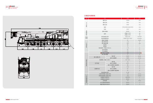
主要技术参数表配重组合表格VHK 0°副臂起重性能表支腿全伸,副臂安装角为0°VHK 20°副臂起重性能表支腿全伸,副臂安装角为20°VHK 40°副臂起重性能表支腿全伸,副臂安装角为40°配重组合表格吊钩负载能力,滑轮数及吊钩质量注:*选装件主要技术参数表主臂起重性能表主臂起重性能表主臂起重性能表主臂起重性能表PAGE21PAGE22副臂起重性能表支腿全伸,副臂安装角为0,副臂长度为43m(36+7),78t配重SAC2200 ALL-TERRAIN CRANE 220 TONS OF LIFTING CAPACITYSAC2200全地面起重机/220吨起重量副臂起重性能表副臂起重性能表 支腿全伸,副臂安装角为20,副臂长度为43m(36+7),78t配重支腿全伸,副臂安装角为40,副臂长度为43m(36+7),78t配重注释起升钢丝绳倍率最大起重量起重模式标志,左边方框表示主臂的工作模式,比如“T”表示伸缩臂;右边方框表示副臂的工作模式,“--”表示副臂没有工作副臂起重工况,如“K”表示可折叠臂,“12.2m”表示副臂长度,“0°”表示副臂安装角“V”表示有主臂延伸臂的情况“HK”表示液压控制安装角可调副臂模式“V”表示有主臂延伸臂的情况,“HK”表示液压控制安装角可调副臂模式主要技术参数表主臂起重性能表注:*需增加附属装置,正后方作业;固定副臂无超起性能表主臂带超起性能表固定副臂带超起性能表固定副臂带超起性能表主要技术参数表主臂起重性能表注:*需增加附属装置,正后方作业;主臂带超起性能表固定副臂无超起性能表固定副臂带超起性能表塔式副臂带超起性能表主要技术参数表主臂性能表(带超起)主臂性能表注:*为必须带辅助装置。
注:*为必须带辅助装置。
副臂性能表(带超起,支腿全伸,360°作业, 165t配重)塔臂性能表(带超起,支腿全伸,360°作业,165t配重)* 副臂连接架2.2m。
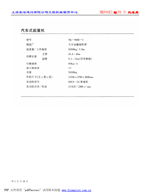
NK500E3型50.5t汽车吊
上海宝冶建设有限公司工程机械租赁中心
NK500E3 型 50.5t 汽车吊
第 7 页 共 10 页
PDF 文件使用 "pdfFactory" 试用版本创建
上海宝冶建设有限公司工程机械租赁中心
NK500E3 型 50.5t 汽车吊
第 8 页 共 10 页
PDF 文件使用 "pdfFactory" 试用版本创建
PDF 文件使用 "pdfFactory" 试用版本创建
上海宝冶建设有限公司工程机械租赁中心
NK500E3 型 50.5t 汽车吊
第 9 页 共 10 页
PDF 文件使用 "pdfFactory" 试用版本创建
上海宝冶建设有限公司工程机械租赁中心
NK500E3 型 50.5t 汽车吊
第 10 页 共 10 页
上海宝冶建设有限公司工程机械租赁中心
NK500E3 型 50.5t 汽车吊
第 3 页 共 10 页
PDF 文件使用 "pdfFactory" 试用版本创建
上海宝冶建设有限公司工程机械租赁中心
NK500E3 型 50.5t 汽车吊
第 4 页 共 10 页
PDF 文件使用 "pdfFactory" 试用版本创建
上海宝冶建设有限公司工程机械租赁中心
NK500E3 型 50.5t 汽车吊
第 1 页 共 10 页
PDF 文件使用 "pdfFactory" 试用版本创建
上海宝冶建设有限公司工程机械租赁中心
NK500E3 型 50.5t 汽车吊
第 2 页 共 10 页
PDF 文件使用 "pdfFactory" 试用版本创建
徐工QUY450
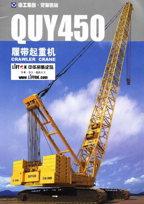
徐工QUY450型450吨履带起重机性能表QUY450履带起重机基本参数QUY450履带起重机臂杆组合QUY450履带起重机超起工况QUY450履带起重机超起工况QUY450履带起重机HB工况性能表(Table 1)HB Standard Mode Total rated lifting load for boom(160t Turntable Counterweight + 40t Truck-body Counterweight)Boom lengthWorking radius 24 30 36 42 48 54 60 66 72 78 846 4507 360 3608 320 320 3209 280 280 280 275 27210 240 240 240 240 240 23511 220 215 215 215 212 205 200 19012 190 190 190 190 190 185 180 170 16514 160 160 155 152 150 150 150 140 135 12510016 132 132 132 126 125 125 122 115 115 1159218 110 110 110 110 107 103 102 100 100 98 8520 97 96 95 92 92 92 90 86 85 82 8022 85 82 82 80 80 80 78 75 74 73 7024 72 72 70 70 70 70 68 64 63 6026 65 65 62 62 62 62 60 57 56 5228 60 57 56 55 55 55 51 50 4530 55 52 50 50 50 50 47 45 4034 43 42 42 42 40 40 37 3438 36 35 35 35 35 33 32 2642 30 30 28 28 27 25 2246 25 24 23 23 20 1750 20 19 18 16 1454 16 14 13 1158 12 12 10 962 9 8 765 6Parts of line 2×18 2×14 2×132×112×112×102×8 2×8 2×7 2×52×4 Hook block 450t 450t 450t 300t300t300t300t300t 300t 150t100t Hook weight 9.66 9.66 9.66 9.48 9.489.489.489.48 9.48 4.63 3.85 If boom length is 60m or 66m or 72m, Hook block maybe choose 220t hook(450t hook splited and 220t hook weight is 7.19t)QUY450履带起重机HJ工况性能表(1)(Table 2)HJ Standard Mode Total rated lifting load for Heavy boom + Fixed Jib(160t Turntable Counterweight + 40t Truck-body Counterweight)Boom length(m) 36 48Jib length(m) 12 24 36 12 24 36 Erection angle(°) 10 30 10 30 10 30 10 30 10 30 10 30 Workingradius (m)14 8516 75 8018 63 33 39 7320 58 31 35 67 33 3922 53 30 32 24 62 32 3624 49 29 30 23 57 31 33 2426 45 27 27 17.521 53 30 31 18 2328 42 26 25 17 19 49 28 29 17.2 2130 40 25 24 16 18 11.5/3244 27 27 16.9 2034 35 24 21 15 16 11 37 26 24 16 18 1138 32 23 19 14 14 10 31 24 22 14.5 16 10.342 29 17 13 12 9 27 23 20 14 14 1046 16 12 11 8.3 23 22 18 13 13 950 14 11 10.18 20 17 12.3 12 8.354 13 9.27.2 17 15 12 11 858 9 7 14.3 11 10 7.362 8 6.8 14 9 766 7 13 8.5 6.770 8 674 7.5 Parts of line(°) 7 3 3 2 2 1 6 3 3 2 2 1 Hook block 100t50t 50t 50t50t12t 100t50t50t 50t 50t 12t Hook weight(t) 3.85 1.71 1.71 1.71 1.710.93 3.85 1.71 1.71 1.71 1.710.93QUY450履带起重机HJ工况性能表(2)(Table 2-1)HJ Standard Mode Total rated lifting load for Heavy boom + Fixed Jib(160t Turntable Counterweight + 40t Truck-body Counterweight)Boom length(m) 60 72Jib length(m) 12 24 36 12 24 36 Erection angle(°) 10 30 10 30 10 30 10 30 10 30 10 30 Workingradius (m)16 8018 80 8020 75 35 42 7722 68 33 39 67 34 4224 60 32 36 24 58 33 3926 53 31 34 23.551 32 37 2428 47 30 32 18 23 46 31 35 23.530 43 29 30 17 21.841 30 33 18 2334 35 27 27 16 19.311.5/3633 29 29 17 2138 29 26 24 15 17 11 28 27 27 16 19 1142 25 25 22 14 16 10 23 24 24 15 17 1046 21 22 20 13.714 9 19 20 21 14 16 9.750 18 18 19 13 13 8.7 16 16 18 13.5 14 954 15 15 17 12 12 8 13 14 15 13 13 8.758 13 14 11.911 7.8 10 11 12 12.5 12 862 11 12 11.510.27.2 8 9 10 12 11 7.866 10 11 10 7 7 8 10 9 7.470 9 9 6.8 7 8 8 7.174 7 8 6.5 5 6 6 778 7 6 4 5 6.682 6 4 586 5 4 Parts of line(°) 6 3 3 2 2 1 6 3 3 2 2 1 Hook block 100t50t 50t 50t50t12t 100t50t50t 50t 50t 12t Hook weight(t) 3.85 1.71 1.71 1.71 1.710.93 3.85 1.71 1.71 1.71 1.710.93QUY450履带起重机重型主臂+塔式副臂工况性能表(Table 3)Standard Mode Total rated lifting load for Heavy boom + Tower Attachment (160t Turntable Counterweight + 40t Truck-body Counterweight)Boom length 72m, Max.boom angle 85°Tower Attachment length(m) 24 30 36 42 48 54 60 66 72 Working radius (m)16 116.9114.918 104.5102.8100.620 94.392.390.188.022 85.283.181.179.277.224 77.575.673.771.970.168.366.626 71.169.267.465.764.062.460.7 50.628 65.763.862.160.558.957.355.7 49.5 35.730 61.159.257.555.954.452.951.4 48.6 34.832 55.253.552.050.549.047.6 46.2 34.234 51.750.048.547.145.644.1 42.7 33.636 48.646.945.444.042.340.9 39.4 32.938 44.242.741.139.438.0 36.6 32.240 41.740.038.436.835.4 33.9 31.542 39.137.636.034.432.9 31.5 29.944 35.433.832.230.7 29.3 27.746 33.331.730.228.7 27.3 25.748 31.529.828.326.9 25.5 23.950 28.126.625.1 23.8 22.252 26.525.023.6 22.2 20.754 25.123.522.1 20.7 19.256 22.120.7 19.3 17.858 20.819.4 18.0 16.660 19.718.2 16.8 15.462 17.1 15.7 14.564 16.0 14.8 13.866 15.1 14.1 13.168 13.5 12.570 12.9 11.972 12.3 11.374 10.876 10.3QUY450履带起重机SHB SSL工况性能表(Table 4)SHB SSL Mode Total rated lifting load for Heavy Boom(160t Turntable Counterweight + 40t Truck-body Counterweight + 250t SuperliftCounterweight,Superlift Counterweight radius of 16m and Superlift mast of 30m)Boom lengthWorking radius 36 42 48 54 60 66 72 78 849 450*10 450* 450*11 450* 450* 410*12 450* 450* 410* 362* 315*14 395 395 395 362* 315* 269* 220*16 340 340 340 340 300* 269* 220* 180* 145*18 304 303 301 300 290 269* 220* 180* 145*20 268 267 265 265 263 256 220* 180* 147*22 239 240 240 236 235 232 220 180* 147*24 218 220 220 218 212 212 211 180* 150*26 195 200 200 200 195 195 193 175 150*28 175 184 185 185 180 180 178 170 150*30 155 169 170 170 168 168 165 165 140*34 140 145 146 145 143 143 142 13538 112 126 127 125 125 125 123 12242 105 110 112 110 110 108 10746 97 98 98 98 96 9550 88 88 87 86 8554 79 79 78 7658 71 70 6862 62 62 6266 55 5770 5272 50Parts of line 2×18 2×18 2×16 2×14 2×12 2×11 2×9 2×7 2×6 Hook block 450t 450t 450t 450t 450t 300t 300t 300t 150t Hook weight(t) 9.66 9.66 9.66 9.66 9.66 6.48 6.48 6.48 4.63 Note:1.The Superlift Counterweight can't leave ground to swing with marking *2.If lifting weight is 150-220t,The Hook can choose 300t or 220t hook(450t hook splited and 220t hook weight is 7.19t).3.150t hook(300t hook splited).QUY450履带起重机SSL工况性能表(Table 5)SSL Mode Total rated lifting load for Heavy Boom + Tower Attachment(160t Turntable Counterweight + 40t Truck-body Counterweight + 250t Superlift Counterweight,Superlift Counterweight radius of 16m and Superlift mast of 30m)Boom length 84m, Max.boom angle 85°Tower Attachment ength(m) 24 30 36 42 48 54 60 66 72 78 84 Working radius (m)16 96.318 86.3 84.520 78.0 76.274.422 71.0 69.267.565.863.824 65.1 63.361.559.958.056.126 60.0 58.156.454.853.051.149.128 55.6 53.651.950.348.546.744.943.3 37.930 51.7 49.748.046.444.742.941.139.6 37.9 26.032 48.4 46.244.542.941.239.537.836.3 37.0 25.317.034 43.141.439.838.136.534.733.3 34.4 24.716.436 40.438.637.035.433.732.130.6 31.5 24.116.038 37.936.134.532.931.329.628.2 28.9 23.415.540 33.832.230.629.027.426.0 26.5 22.615.042 31.730.128.527.025.423.9 24.3 20.714.744 29.928.226.625.123.522.1 22.3 18.914.346 26.424.923.421.820.4 20.5 17.214.048 24.823.321.820.318.8 18.9 15.713.750 21.820.318.817.4 17.3 14.613.452 20.418.917.416.0 15.9 13.712.854 19.217.716.214.9 14.7 12.912.056 16.515.014.1 13.9 12.111.258 15.414.313.3 13.1 11.410.560 14.613.612.7 12.4 10.79.862 12.912.0 11.7 10.19.164 12.311.4 11.0 9.58.566 11.810.8 10.4 8.98.068 10.2 9.8 8.47.5 70 9.7 9.3 7.8 6.9 72 9.2 8.8 7.4 6.5 74 8.3 6.9 6.0 76 7.8 6.5 5.6 78 7.4 6.1 5.2 80 7.0 5.7 4.8 82 5.3 4.4 84 4.9 4.0 86 3.7QUY450履带起重机SLB工况性能表(一)(Table 5-1)SLB Superlift Mode Total rated lifting load for Light Boom (160t Turntable Counterweight + 40t Truck-body Counterweight + 230t SuperliftCounterweight,Superlift Counterweight radius of 16m and Superlift mast of 30m)Boom length(m) 78 84 90 96 102 108 114 120 126 Working radius (m)16 175*18 175* 123*20 173* 123* 78.3*22 172* 125* 77.4*46.2 37.824 171* 125* 76.5*46.2 37.826 166* 124* 75.6*45.5 37.828 151* 124* 75.6*45.5 37.830 158 124* 74.7*45.5 37.834 138 117* 72* 44.8 37.838 120 115 68.4*44.1 37.842 107 105 67.5*43.4 36.446 95 93 64.8*42 35.750 85 84 62.1*42 3554 77 76 55.8*41.3 34.358 70 69 57.6 38.5 33.662 64 63 54.9 36.4 32.266 59 57 51.3 33.6 31.570 54 53 47.7 30.8 30.874 50 49 43.2 28.7 29.478 45 40.5 26.6 2882 41 37.8 24.5 25.986 35.1 23.1 24.590 32.4 21.7 23.194 29.7 19.6 21.798 17.5 20.3102 18.9 106 16.8110 15.4 Parts of line 2×8 2×7 2×5 2×5 2×4 2×3 2×3 1×4 1×3 Hook block 300t 300t 150t 150t 150t 100t 100t 100t 50t Hook weight(t) 6.48 6.48 4.63 4.63 4.63 3.85 3.85 3.85 1.71 Note:1.The Superlift Counterweight can't leave ground to swing with marking *2.If lifting weight is 150-220t,The Hook can choose 300t or 220t hook(450t hook splited and 220t hook weight is 7.19t).3.150t hook(300t hook splited)QUY450履带起重机SLB工况性能表(二)(Table 5-2)SLB Superlift Mode Total rated lifting load for Light Boom(160t Turntable Counterweight + 40t Truck-body Counterweight + 230t SuperliftCounterweight,Superlift Counterweight radius of 16m and Superlift mast of 30m)Boom length(m) 78 84 90 96 102 108 114 120 126 Working radius (m)16 170 16918 146 145 141 12320 128 127 126 123 105 78.322 113 112 111 111 105 77.424 101 100 99 98 98 76.5 53.226 91 90 89 88 88 75.6 53.2 45.528 82 81 81 80 79 72.9 52.5 45.530 75 74 73 73 72 65.7 51.1 45.5 37.834 63 62 62 61 60 54.9 42.7 42.7 37.138 53 53 52 52 51 45.9 35.7 35.7 35.742 46 45 45 44 43 39.6 30.8 30.8 30.146 40 39 39 38 37 34.2 26.6 25.9 25.950 35 34 33 32 31 29.7 23.1 22.4 22.454 31 30 29 28 27 25.2 19.6 19.6 19.658 27 26 25 24 23 22.5 16.8 16.8 16.862 23 22 21 21 20 18.9 14.7 14.7 1466 20 19 18 18 17 16 12.6 12.6 12.670 17 16 16 15 14 13 11.2 10.5 10.574 14 13 12 12 11 9.8 9.1 878 11 10 9.5 9 8 7.2 6.382 8.5 8 7 4.5Parts of line 2×7 2×7 2×6 2×5 2×4 1×6 1×4 1×4 1×3 Hook block 300t 300t 150t 150t 150t 100t 100t 100t 50t Hook weight(t) 6.48 6.48 4.63 4.63 4.63 3.85 3.85 3.85 1.71 Note: 1.If lifting weight is 150-220t,The Hook can choose 300t or 220t hook(450t hook splited and 220t hook weight is 7.19t).2.150t hook(300t hook splited)QUY450履带起重机SLB工况性能表(三)(Table 5-3)SLB Superlift Mode Total rated lifting load for Light Boom(160t Turntable Counterweight + 40t Truck-body Counterweight + 230t SuperliftCounterweight,Superlift Counterweight radius of 14m and Superlift mast of 30m)Boom length(m) 78 84 90 96 102 108 114 120 126 Working radius (m)16 174 16818 147 147 137 12020 127 126 126 120 102 76.5 51.822 111 110 110 110 102 75.6 51.8 44.8 36.424 98 97 97 97 97 74.7 51.8 44.8 36.426 87 87 87 86 86 73.8 51.1 44.1 36.428 78 78 78 78 77 69.3 51.1 44.1 36.430 71 71 71 70 70 62.1 48.3 44.1 36.434 59 59 59 58 58 52.2 39.9 39.9 36.438 50 50 50 49 49 43.2 33.6 33.6 33.642 43 43 42 42 42 36.9 28.7 28.7 28.746 37 37 37 36 36 31.5 24.5 24.5 24.550 33 32 32 31 31 27.9 21 21 2154 29 28 28 27 27 23.4 18.2 18.2 17.558 25 25 24 24 23 20.7 15.4 15.4 15.462 22 22 21 21 20 18 13.3 13.3 13.366 20 19 19 18 17 15.3 11.9 11.2 11.270 18 17 16 16 15 13.5 9.8 9.8 9.174 15 14 14 13 10.8 8.4 8.4 7.778 12 12 11 9.9 7 7 6.382 10 10 8.1 6.3 5.686 8 7.2 4.290 3.5Parts of line 2×7 2×7 2×5 2×5 2×4 1×6 1×4 1×4 1×3 Hook block 300t 300t 150t 150t 150t 100t 100t 100t 50t Hook weight(t) 6.48 6.48 4.63 4.63 4.63 3.85 3.85 3.85 1.71 Note: 1.If lifting weight is 150-220t,The Hook can choose 300t or 220t hook(450t hook splited and 220t hook weight is 7.19t).2.150t hook(300t hook splited)。
- 1、下载文档前请自行甄别文档内容的完整性,平台不提供额外的编辑、内容补充、找答案等附加服务。
- 2、"仅部分预览"的文档,不可在线预览部分如存在完整性等问题,可反馈申请退款(可完整预览的文档不适用该条件!)。
- 3、如文档侵犯您的权益,请联系客服反馈,我们会尽快为您处理(人工客服工作时间:9:00-18:30)。
SANY Full Hydraulic Truck Crane Series
SANY is Determined to Achieve World-class Quality, SANY Truck Crane Pilots New Standard with New & High Quality.
Cab Page 1 Power System Page 2Boom System Page 3
Hydraulic System Page 4
Slewing & Hoisting Mechanism Page 5
Chassis & Electric System Page 6
Construction Cases Page 6
Specifications Pages 7-14
Complete Customer Support Page 15
Cab
Unique and exquisite appearance as well as safe and comfortable driving environment brings you a new feeling.
Cab of Lower Structure Streamline Full-width Cab:
Operating Instrument Panel:
Electronic Simulation Instrument:
Radio/ Cassette Player Device:
Cab of Upper Structure
Engine production technology from USA Cummins brings you the first-rank power system.
Power System
Reliability
Good Power Performance and Large Torque Reserve
Good Economy and Low Fuel and Engine Oil Consumption
Excellent Plateau Adaptability
Green and Environment-friendly
Rational Structure and Convenient Operation and Maintenance
Boom System
Hydraulic System
Optimal boom mechanism brings you powerful hoisting capacity.
Out Rigger Structure
Characteristics of Out Rigger
Torque Limiter
Complete and reliable hydraulic safety guarantee system keeps it stable all the time.
Hydraulic System of Upper Structure
Controlling Oil Circuit
Technical Parameters of Hydraulic System
Slewing & Hoisting Mechanism Chassis & Electric System
Accurate slewing & hoisting mechanism makes every working condition perfect.
Slewing Mechanism Hoisting Mechanism
Optimal chassis design leads to swift shifting power.
Technical Characteristics of Chassis
Electric System
Construction Cases
Hoisting Performance T able of Qy26 Auxiliary Boom
Complete Customer Support
With a SANY Truck Crane, you can enjoy the commitment of overall services supplied by SANY.
Service Response
Guarantee for Service Commitment
In-sale Service Pre-sale Service After-sale Service。
