ABB新Emax+E系列低压空气断路器
ABB断路器 Emax_Bas参数

42 42 42 42
65 55 65 55
85 65 85 65
130 85 130 65
65 65 65 65
75 75 75 75
100 85 85 85
130 100 100 85
130 85 130 65
75 75 75 75
100 85 100 85
150 100 150 100
100 100 100 100
结构特点
全系列具有相同的高度与深度尺寸
大大提高开关柜设计的标准化 简化母线系统的设计 开关柜前立面统一、美观,操作方便
抽出式的深度适合安装在深度 500mm 的开关柜内 宽度324mm (额定电流高达 2000A) 的抽出式断路器可安裝在 隔间宽 400mm 的开关内
>>结构特点
PR121/P- LI, LSI,LSIG
过载保護 (L) 选择性短路保护(S) 瞬時短路保護 (I) 接地故障保護 (G) 方向性保护 (D) 相不平衡保护(U) 超温保护 (OT) 负载控制 (K)
欠压保护 (UV) 过压保护(OV) 剩余电压保护 (RV)
低频保护(UF) 高频保护(OF) 相序保护(只报 警) 双 „‟S‟„ 功能 双 ’‘G‟„ 功能 双组参数设定 现场升级(模块 组合)
65 65 B
42 42 B
55 42 B
65 42 B
10 A
65 65 B
75 65 B
75 65 B
85 65 B
15 A
75 75 B
100 75 B
100 75 B
100 85 B
ABB低压产品快速选型
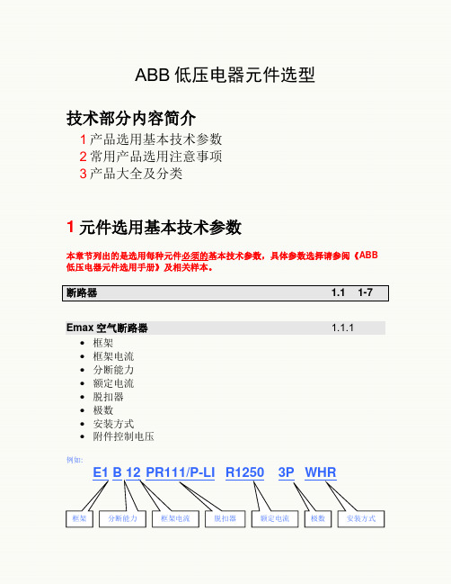
ABB低压电器元件选型技术部分内容简介1产品选用基本技术参数2常用产品选用注意事项3产品大全及分类1元件选用基本技术参数本章节列出的是选用每种元件必须的基本技术参数,具体参数选择请参阅《ABB 低压电器元件选用手册》及相关样本。
断路器 1.1 1-7Emax空气断路器 1.1.1•框架•框架电流•分断能力•额定电流•脱扣器•极数•安装方式•附件控制电压例如:E1 B 12 PR111/P-LI R1250 3P WHR框架分断能力框架电流脱扣器额定电流极数安装方式技术参数代号解释框架: E1 E1 Iu = 800~1250AE1 Iu = 800~1250AE2 Iu = 1250~2000AE3 Iu = 1250~3200AE4 Iu = 3200~4000AE6 Iu = 3200~6300A分断能力: B B: 40kAB: 40kAN: 65kAS: 75kAH: 100kAV: 150KAL: 130KA框架电流:12 1250A(E1,1250A--E6,6300A)脱扣器:PR111/P-LI PR111/P-LI PR111脱扣器,二段保护PR111/P-LI PR111脱扣器,二段保护PR111/P-LSI PR111脱扣器,三段保护PR111/P-LSIG PR111脱扣器,四段保护PR112/P-LSI PR112脱扣器,三段保护PR112/P-LSIG PR112脱扣器,四段保护PR112/PD-LSI PR112脱扣器,三段保护带对话单元PR112/PD-LSIG PR112脱扣器,四段保护带对话单元PR113/P-LSIG PR113脱扣器,四段保护PR113/PD-LSIG PR113脱扣器,四段保护带对话单元额定电流:R1250 1250A(E1,250A--E6,6300A)极数: 3P 3极(3或4极可选)安装方式:WHR W:抽出式(W:抽出式F:固定式)HR:水平后接线HR 水平后接线VR 垂直后接线F 延伸接线FL 端面接线(固定式无)附件控制电压:需要注明控制电压附件---YO,YC,YU,MIsomax塑壳断路器 1.1.2 •框架•框架电流•额定电流•分断能力•脱扣器(TM热敏电磁脱扣器型无须提供)•极数•安装方式•附件控制电压例如:TM热敏电磁脱扣器型:S2 S – 160 / R125 3P FFC框架分断能力框架电流额定电流极数安装方式技术参数代号解释框架: S2 S2S1 I=125S2 I=160S3 I=160,250S5 I=400,630S6 I=630,800分断能力:S SS1: B / N KA数值请查样本S2: B / N / S KA数值请查样本S3: N / H / L KA数值请查样本S5: N / H / L * KA数值请查样本S6: N / S / H / L KA数值请查样本框架电流:160A 参阅框架额定电流:R125 125AS1-125, 10A----S6-800, 800A极数:3P 3极(3或4极可选)安装方式:FFC F: 固定式F: 固定式P: 插入式(S6/S7不适用)W: 抽出式(S1/S2不适用)FC: 铜电缆前接线F: 前接线EF: 加长前接线ES: 加长扩展前接线FC: 铜电缆前接线R: 螺纹后接线RC: 铜/铝后接线附件控制电压:需要注明控制电压附件---YO,YC,YU,M框架 分断能力 框架电流 脱扣器 额定电流 极数 安装方式微处理器脱扣器型:S4 N – 250 / In125 LSIG 3P FFC技术参数 代号 解释框架:S4S4 I=160,250 S4 I=160,250 S5 I=400,630 S6 I=630,800 S7 I=1250,1600S8 I=2000, 2500, 3200分断能力: N NS4: N / H / L KA 数值请查样本 S5: N / H / L KA 数值请查样本 S6: N / S / H / L KA 数值请查样本 S7: S / H / L KA 数值请查样本 S8: H / V (新品)KA 数值请查样本框架电流: 250 参阅框架 额定电流: R125 125AS4-160, 100A----S6-800, 3200A脱扣器: LSIG LSIG: 长延迟+短延迟+瞬动+接地故障I: 短路瞬动 LI: 长延迟+瞬动LSI: 长延迟+短延迟+瞬动LSIG: 长延迟+短延迟+瞬动+接地故障 LRIU: 长延迟+堵转+瞬动+断相或相不平衡( PR010/K,PR212/D,PR212/T 参见样本 )极数: 3P 3极(3或4极可选)安装方式: FFC F: 固定式F: 固定式P: 插入式(S6/S7不适用) W: 抽出式(S1/S2不适用)FC: 铜电缆前接线 F: 前接线 EF: 加长前接线 ES: 加长扩展前接线 FC: 铜电缆前接线 R: 螺纹后接线 RC: 铜/铝后接线 附件控制电压: 需要注明控制电压附件---YO ,YC ,YU ,MIsomax限流型塑壳断路器 1.1.3 •框架•框架电流•额定电流•分断能力•极数•安装方式附件控制电压例如:技术参数代号解释S3 X - 125 / R80 3P FEF框架分断能力框架电流额定电流极数安装方式框架: S3 S3S2 I=1~100 分档S3 I=125,200S4 I=250S6 I=400,630分断能力:X XS2X分断能力70KA; S3X,S4X,S6X分断能力200KA框架电流:125 参阅框架额定电流:R80 80AS2X-80: 1~80(19档), 3P,单磁 (参见样本)S2X-100:1~100(16档), 3P, 参见样本S3X-125: 32,50,80,100,125S3X-200: 125,160,200S4X-250: 100,160,250S6X-400: 320,400S6X-630: 630极数:3P 3极(3或4极可选)安装方式:FEF F: 固定式F: 固定式P: 插入式(S6)W: 抽出式(S1/S2不适用)EF: 加长前接线F: 前接线EF: 加长前接线ES: 加长扩展前接线FC: 铜电缆前接线R: 螺纹后接线RC: 铜/铝后接线附件控制电压:需要注明控制电压附件---YO,YC,YU,M一体化剩余电流断路器 1.1.4•框架•框架电流•额定电流•极数•安装方式•排列•附件控制电压例如:S2 N – 160 / R125 4P FFC +RC212/ 2V框架分断能力框架电流额定电流极数安装方式脱扣器技术参数代号解释框架、分断能力、框架电流:S2N-160只有两种S2N-160,S3N-250额定电流:R80 80AS2-160: 12.5,16,20,25,32,40,50,63,80,100,125,160S3-250: 32,40,50,63,80,100,125,160,200,250S3及以下磁脱扣固定为10倍,非标可有5倍或单磁. 极数:4P 4P安装方式:FFC F: 固定式F: 固定式FC: 铜电缆前接线F: 前接线(S3N)FC: 铜电缆前接线(S2N)排列:V V:垂直安装V:垂直安装,H:水平安装附件控制电压:需要注明控制电压附件---YO,YC,YU,M切换回路数回路数额定电流额定电流 安装方式 电源自动切换装置1.1.5DPT• 切换回路数 • 额定电流例如:DPT / SE1600技术参数代号 解释 切换回路数: SESE 双电源切换,TE 三电源切换 额定电流:1600 1600A 主回路电流Isomax 低压塑壳断路器配合剩余电流保护继电器1.1.6RC212• 框架电流• 安装方式例如:RC212 / 2 / 垂直安装技术参数 代号解释额定电流: 2(代码) 配S2-160/4P: 选 2 配S2-160/4P: 选 2 配S3-250/4P: 选 3 安装方式: 垂直安装 垂直安装与断路器叠装: 垂直安装 与断路器并装: 水平安装RCD• 剩余动作电流例如:剩余动作电流互感器内径主回路电流极数辅助触头数量控制电压RCD 0.03技术参数代号解释剩余动作电流: 0.03 30 mA剩余动作电流:0.03 - 0.1 - 0.3 -0.4 - 1A剩余电流保护继电器 1.1.7 RCQ•互感器内径例如:RCQ Ф110技术参数代号解释互感器内径: 110mm Φ110 mmΦ60 mm互感器内径Φ110 mm互感器内径工控产品及接线附件 1.2 1-3接触器系列 1.2.1接触器 1.2.1a •主回路电流•控制电压(交、直流)•极数•辅助触头数量例如:A30 – 30 - 10 控制电压ac220V技术参数代号解释主回路电流: 30 30A极数: 30 3常开前一位代表常开,后一位代表常闭,数字为数量辅助触头数量10 一常开前一位代表常开,后一位代表常闭,数字为数量控制电压(交、直流)ac220V 交流220VTA热过载继电器 1.2.1b •热脱扣电流•轻重载(450以上)例如:T450 DU 400主回路电流轻重载脱扣电流技术参数代号解释主回路电流: 450 450A轻重载:DU DU普通DU普通SU重载中间继电器 1.2.1c •触点数、主触点组合方式(常开、常闭)•控制电压、交、直流操作例如:N 63 E 控制电压ac220V触点数、主触点组合方式控制电压、交、直流操作技术参数代号解释触点数、主触点组合方式:63 6常开,3常闭前一位代表常开,后一位代表常闭,数字为数量控制电压、交、直流操作:控制电压ac220V额定电流触点数、主触点组合方式控制电压、交、直流操作框架电流和分断能力额定电流ESB接触器 1.2.1d •额定电流•主触点组合方式(常开、常闭)•控制电压、交、直流操作•灯具应用请参阅样本例如:ESB 63 - 31 控制电压ac220V技术参数代号解释额定电流:63 63A20 对AC1/AC7a负载24 对AC1/AC7a负载40 对AC1/AC7a负载63 对AC1/AC7a负载触点数、主触点组合方式:31 6常开,3常闭ESB20: 可选: 20, 02, 11ESB24: 可选: 40, 04, 22, 31, 13ESB40: 可选: 40ESB63: 可选: 40前一位代表常开,后一位代表常闭,数字为数量控制电压、交、直流操作:控制电压ac220V灯具应用:请参阅样本电动机起动器 1.2.2 •框架电流和分断能力•热脱扣电流例如:MS 325 - 20框架电流和分断能力:325 MS325 50KA,0.1-25AMS325 50KA,0.1-25AMS450 50kA,16~50AMS451 50KA,16~50AMS495 50KA,40~100AMS496 100KA,40~100AMS497 100KA,16~100A额定电流20 20APSS、PST、PSTB软启动器 1.2.3 •电机额定电流(结合功率考虑)•负载类型(重、轻载)•控制电源电压例如:PSS - 18/30电机额定电流技术参数代号解释电机额定电流:18/30 18A外接法/30A内接法(PSS)负载类型(重、轻载):参阅样本控制电源电压:参阅样本开关及熔断器设备 1.3 1-3开关熔断器组 1.3.1 OS、OESA•额定电流•极数例如:OESA 250 D3PL 3P额定工作电流极数额定工作电流:250 250A极数:3P 3极负荷开关/隔离开关 1.3.2 OT、OETL•额定电流•极数例如:OETL 250 K3 3P额定工作电流极数技术参数代号解释额定工作电流:250 250A极数:3P 3极Easyline熔断丝切换隔离开关 1.3.3 XLP三极•额定电流例如:XLP 00额定电流技术参数代号解释额定电流:00 160A按照样本根据电流选择型号线路保护装置 1.4极数脱扣特性额定电流极数脱扣特性额定电流数量剩余电流动作电流微型断路器 1.4.1 •额定电流•极数(最后位数字为可选项,1为1极,2为2极…依此类推,例如S261)•分断能力•脱扣特性(B、C、D、K等)例如:S 261 – C 20技术参数代号解释极数: 261 1极最后位数字为可选项,1为1极,2为2极…依此类推脱扣特性: C CB、C、D、K、Z根据样本,由不同系列不同电流而不同额定电流:20 20A根据样本,由不同系列有不同电流范围过电流保护电磁式剩余电流动作断路器 1.4.2DS250S•额定电流•极数(最后位数字为可选项,1为1极,2为2极…依此类推,例如DS252) •分断能力•脱扣特性(B、C)•剩余电流动作电流例如:DS253S-C 40 / 0.03技术参数代号解释极数:DS253 3极极数脱扣特性额定电流数量剩余电流动作电流最后位数字为可选项,2为2极…依此类推(无1极)脱扣特性: C CB、C两种额定电流:40 40A根据样本,由不同系列有不同电流范围剩余电流动作电流:0.03 30mADS9•额定电流•极数(最后位数字为可选项,1为1极,2为2极。
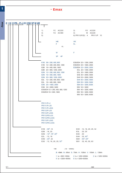
ABB Emax
名称/符号
常用附件
固定式适用
合闸/分闸线圈 (YO/YC)
是
欠压线圈 (YU)
是
储能电机 (M)
是
过流脱扣器动作机械信号
是
过流脱扣器动作机电信号
是
断路器分合辅助接点
是
断路器连接、试验、隔离位置信号接点
否
储能完毕信号接点(M)
1/3
ABB 低压电器元件选用手册
5) 带机械电气报警复位指示
6) PR112/P(D)带4对、PR111/P带10对辅助接点
选配附件参阅下页表格
主接线方式:
HR : 水平后接线
VR : 垂直后接线
F : 延伸接线
FL : 端面接线
固定式无FL端面接线
(未说明时按本公司常规供货)
安装方式可选: W : 抽出式
F : 固定式
极数可选:
E3H : 12, 16, 20, 25, 32 E3L : 20, 25 E4S : 40 E4H : 32, 40# E6H : 50#, 63# E6V : 32, 40, 50, 63
分断能力:
B : 40kA N : 65kA S : 75kA H : 100kA V : 150kA L : 130kA
ABB 低压电器元件选用手册
1/2
1
空气断路器 - Emax
空气断路器 - Emax
说 明:
1. 微处理器保护脱扣器整定范围:(因技术更新,整定参数和范围可能有变)
对于PR111/P保护脱扣器:
过载长延时整定(L): 短路短延时整定(S): 短路瞬动整定(I): 接地故障整定(G):
ABB断路器产品样本
技术资料断路器类产品备件产品(低压产品服务供应商专用)缺图储备空气断路器和塑壳断路器的备件是对电气系统进行正确维护的必要条件。
尤其对于那些建立于多年前,且有部分所用低压元器件正被逐渐淘汰的电气系统,更显重要。
ABB低压产品业务部备件库存可为客户提供长期的供货保证。
从80年代迄今生产的所有断路器,ABB均做了足够的备件库存,并为您提供有效的备件服务。
ABB低压产品业务部是唯一可提供有质量保证的原装备件供应商,可按客户所需,提供整套备件方案。
并可在本地灵活安排备件供应。
为确保给客户提供最大限度的支持,简化备件的选型和订购,ABB低压产品业务部还构建了密集的服务供应商网络,其专业的服务人员可直接为您解答各种产品问题,并快速处理各种需求。
本样本能帮助简化备件的选型和订货。
此外,备件的型号和参数以标签形式贴在断路器上,查找方便快捷。
ABB低压产品业务部 - 技术服务技术技能 掌控于心备件产品 一应俱全目录 页2E m a x E3I s o m a x S4T m a x T1M e g a m a x F1/1断路器备件产品1M e g a m a xF空气断路器 - Megamax FMegamax F1 / F2产品结构端子夹头电流互感器与电子脱扣器的连线 (AR1)电流互感器与电子脱扣器的连线 (PR1)电子脱扣器的脱扣线圈(YO1)1/2断路器备件产品1M e g a m a x F空气断路器 - Megamax F订货资料Megamax F1 / F21/3断路器备件产品1M e g a m a x F空气断路器 - Megamax F订货资料Megamax F1 / F21/4断路器备件产品1M e g a m a x F空气断路器 - Megamax F产品结构Megamax F4 / F5 / F6端子夹头电流互感器与电子脱扣器的连线 (AR1)电流互感器与电子脱扣器的连线 (PR1)电子脱扣器的脱扣线圈(YO1)前档1/5断路器备件产品1M e g a m a x F空气断路器 - Megamax F订货资料Megamax F4 / F5 / F61/6断路器备件产品1M e g a m a x FMegamax F4 / F5 / F6空气断路器 - Megamax F订货资料1/7断路器备件产品1M e g a m a x F空气断路器 - Megamax F订货资料Megamax F4 / F5 / F62/1断路器备件产品2E m a xE220177空气断路器 - Emax E产品结构连线灭弧罩抽出部分的二次插件接地插组件提升板2/2断路器备件产品2E m a xE空气断路器 - Emax E订货资料Emax E1 / E63/1断路器备件产品3I s o m a xS空气断路器 - Isomax S 系列产品结构注: 如需订购相关备件,请与ABB 低压产品业务部联系剩余电流底座接4/14T m a x T断路器备件产品T1T2T3T4T5T6空气断路器 - Tmax T产品结构注: 如需订购相关备件,请与ABB 低压产品业务部联系备检维升支培长久的保证:库存备件齐全,涵盖了 ABB 在中国所销售的各类通过对断路器进行全面检修,可恢复断路器电气及机械部件的性提供整套的预防性和维护方案,提高系统的可靠性和安全性,并借助转换套件,采用新型断路器替换原有的旧断路器。
ABB Emax空气断路器安装使用说明

其中最重要的一项创新便是采用双向柱型提升端子,它使 接线更简单、快捷。此外,因其可以防止占用空置电缆 座,还可以避免误接线。因此,这种高度的防护措施可以 从一开始便防止因接线错误引发的工业事故。
终端配电产品
产品概述 - S200 系列
S200 系列是应市场需求而最新推出的完整系列产品,包括微型断路器和剩余电流保护产品。因
1 其先进的技术性能,可满足所有设备和客户的安装需求,并为其提供最佳的解决方案,广泛适 用于住宅、商业和工业所有的配电场合。
产品概述
新的 S200 系列产品包括:
微型断路器(MCB): ● SH200 ● S200 ● S200M ● S200P ● S200U ● S200UP
外形尺寸图...........................................................................................................2/17
剩余电流动作保护器
3 3)剩余电流动作保护器 — GSH200、GS200、GDA200、DDA200、F200 产品概述................................................................................................................. 3/1 2 型号说明................................................................................................................. 3/4 产品标识................................................................................................................. 3/5 技术数据一览表 .................................................................................................. 3/6 订货资料..............................................................................................................3/10 外形尺寸图...........................................................................................................3/26
空气断路器-Emax2(新E型)
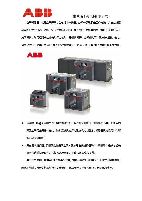
空气断路器,就是空气开关,在电路中作接通、分断和承载额定工作电流,并能在线路和电动机发生过载、短路、欠压的情况下进行可靠的保护。
断路器的动、静触头及触杆设计成平行状,利用短路产生的电动斥力使动、静触头断开,分断能力高,限流特性强。
电力、自动化领域的领导厂商ABB旗下的空气断路器- Emax 2 (新E型)凭借优异性能备受青睐。
●短路时,静触头周围的芳香族绝缘物气化,起冷却灭弧作用,飞弧距离为零。
断路器的灭弧室采用金属栅片结构,触头系统具有斥力限流机构,因此,断路器具有很高的分断能力和限流能力。
●具有复式脱扣器。
反时限动作是双金属片受热弯曲使脱扣器动作,瞬时动作是铁芯街铁机构带动脱扣器动作。
脱扣方式有热动、电磁和复式脱扣3种。
空气开关内部比较复杂,原理却甚为简单。
它在入线和出线间串了个十几二十圈的电感,电流足够时吸合带动机械杠杆而动作保护。
比较安全又不用换保险,是很好的推荐。
自动空气开关也称为低压断路器,可用来接通和分断负载电路,也可用来控制不频繁起动的电动机。
它功能相当于闸刀开关、过电流继电器、失压继电器、热继电器及漏电保护器等电器部分或全部的功能总和,是低压配电网中一种重要的保护电器。
自动空气开关具有多种保护功能(过载、短路、欠电压保护等)、动作值可调、分断能力高、操作方便、安全等优点,所以目前被广泛应用。
如果您了解更多有关新E型空气断路器方面的信息,在此推荐您联系南京首科机电有限公司咨询详情。
南京首科机电有限公司集生产、贸易、技术、服务于一体的机电专业性公司。
经营广泛、品种繁多,主营批发零售各国知名低压电器、电工器材、工业用通风及抽风系统。
公司以“诚信铸就品牌,服务带来效益”的经营理念。
推行“VIP”式的营销服务机制,努力做好售前、售中、售后服务,并为用户建立档案,定期开展大客户综合回访,赢来了越来越宽广的市场空间。
公司主要代理销售品牌:总代理ABB、施耐德电气、〈FUI〉富士电机、〈MITSUBISHI〉三菱电机、〈OMRON〉欧姆龙自控元器件、美国通用GE电器、韩国LS产电、士林电机、、西门子、火灾监控系统、工业插头插座、订制配电箱配电柜。
ABB最新面价表

单价包括:
1.固定式断路器本体 3.附件(NST) 4.接线形式
- 分闸线圈 (YO) 220V - 上下均为水平2.脱扣器 - 合闸线圈 (YC) 220V
- PR121/P-LI / LSI / LSIG - 弹簧储能电动机 (M) 220V
- PR122/P-LI / LSI / LSIG - 机械和电气指示 (保护器动作显示)
- PR123/P-LSI / LSIG - 辅助触头(CO) - 4CO
- 外加中性线电流互感器 (只适用于3极,4段保护的断路器)
- 开关电源 (只适用于PR122,PR123脱扣器的断路器)
单价包括:
1.固定式断路器本体 3.附件(NST) 4.接线形式
- 分闸线圈 (YO) 220V - 上下均为水平2.脱扣器 - 合闸线圈 (YC) 220V
- PR121/P-LI / LSI / LSIG - 弹簧储能电动机 (M) 220V
- PR122/P-LI / LSI / LSIG - 机械和电气指示 (保护器动作显示)
- PR123/P-LSI / LSIG - 辅助触头(CO) - 4CO
- 外加中性线电流互感器 (只适用于3极,4段保护的断路器)
- 开关电源 (只适用于PR122,PR123脱扣器的断路器)。
ABB SACE Emax 2 空气电路断路器产品说明说明书

ABB’s Low Voltage Products Division is proud to present SACE Emax 2,its next generation of air circuit-breakers. Over 70 years of cutting edge research and experience inthe electromechanical industry has allowed ABB SACE to create this new benchmark of air circuit-breakers. Not only does Emax 2 meet or exceed the standard performances and functions that the market demands from an air circuit-breaker, but it has evolved into a true power manager. Emax 2 and its Ekip brand of trip units and accessories contain the perfect blend of control, connectivity, performance, ease of use and safety to efficiently satisfy any application or need.− A patented, Power Controller moni-tors and controls power usage toreduce management costs.−Extensive, direct communication abilities simplify network integrationand eliminate the need for costly and difficult conversion components.−Optimal frame organization and ac-curate design provide the ability forhigh performance switchboards andswitchgear with a reduction of bothmaterials and space required.−Busbar friendly, modifiable terminals eliminate the need to bend and ex-tend bus bar and provide quick, easy installation.−Large, color touchscreen interfaces allow for clear navigation, creating asimple and quick way to find informa-tion or make adjustments.− A wide variety of accessories have been designed to simplify use orinstallation and to increase safety.−The Emax 2 contains several features that are either new to the market orsuperior to existing solutions, mak-ing it the best choice for low voltage network needs.ControlThe Power Controller function of Emax 2uses a patented algorithm to determinethe average absorbed power over aperiod of time and then controls a loadlist to maintain the maximum power limitspecified by the user. The elimination ofinstantaneous based measurements andability to synchronize with utility mea-surement devices creates an efficientenvironment that saves on electricitybills without the need for additionalmonitoring systems.The Ekip Link system and Ekip ControlPanel enable local monitoring of circuit-breakers and switchgear functions in anindividual switchboard. They require noprogramming and are available for eventhe most basic Emax 2 trip unit, provi-ding an economic way for a small plantto increase monitoring capabilities or alarge plant to simplify local supervisionand maintenance.A Network Analyzer feature is able onEmax 2 to analyze the quality of powerin real time, with extreme precision inaccordance with EN 50160 and IEC6100-4 30. As a result, it is possibleto identify the causes of an increase ofpower lost or a reduction of the workinglife of cables and capacitors without ha-ving to install costly, external instrumen-tation. With Emax 2’s Network Analyzer,malfunctions can be prevented andinstallation efficiency and the workinglife of appliances can be increased.The Ekip Synchrocheck module enablesthe control of the synchronism conditionfor placing two lines in parallel beforeenabling circuit breaker closing.The ability of the Emax 2 to provide thisfeature as a module eliminates the needfor the purchase and installation of inde-pendent monitoring systems.Emax 2 offers Generator versions of itsEkip Touch and Ekip Hi-touch trip units.These trip units include all the functionsof true generator protection switchgearwithout the need for external relays ordevices, wiring or inspections. The Gversion offers a safe control solutionthat is immediately ready for use.ConnectivityEvery Emax 2 can be equipped with multiple cartridge-type communication modules at any time. The modules allow the circuit breakers to be directly integrated into automation and ener-gy management systems through the seven most popular global protocols; including IEC 61850 for the creation of Smart Grid Networks. All functions can be accessed via the internet, in comple-te safety, using the Ekip Link switchgear monitoring system.Not only can the rear terminals of Emax 2 be field rotated from horizontal to vertical, but they have been specifically designed to fit the most common bus configurations. Each terminal has been created to the standard width of bus bar for that amperage and is equipped with one, two or three terminal stabs for easy connection of one to four bus runs. The terminal technology provides the oppor-tunity for easy connection and installati-on with less bus bar stock required.The Ekip Supply Module can be con-nected to any voltage in AC or DC to internally supply auxiliary power for the trip units and terminal box modules consecutively. The need for any external power supply converter elsewhere in the cabinet is eliminated, saving both space and cost.The neutral position on Emax 2 can be modified from left to right to provide ultimate flexibility. In addition, the E6.2 is available with neutral conductor sizes of 50% or 100% to allow for the correct sizing of bus bar and an opportunity to reduce construction costs. PerformanceEmax 2 uses four frame sizes, each only as wide as the amperage need requires, so that designers can optimize their space and material. The breaker design and quality materials allow for a small size while maintaining the high perfor-mances required by the most deman-ding conditions.The family of Emax 2 contains:−E1.2, 1600A with a 440V Icu of 66kA and Icw 1s of 50kA in a 210mmwidth.−E2.2, 2500A with a 440V Icu of100kA and Icw 1s of 85kA in a276mm width.−E4.2, 4000A with a 440V Icu of150kA and Icw 1s of 100kA in a384mm width.−E6.2, 6300A with a 440V Icu of200kA and Icw 1s of 120kA in a762mm width.Emax 2 contains new generationRogowski sensors that allow the mostprecise measurement on the market.The tolerance to 1% of the actual valueof current, 0.5% of voltage and 2% ofpower and energies guarantee precisionand enable the circuit-breaker to act asa measurement device in switchgear.Measurements can be read directly onthe wide trip unit display so additionaldevices can be eliminated.The Ekip Fan Module continuouslymonitors the internal temperature at thefixed part and activates cooling fans ifrequired. This allows for the ability ofincreased current-carrying capacity inswitchgear.Ease of use and safetyEmax 2 is the first circuit-breaker tooffer large, color touch screen displays.They provide clear, easy navigation forquick access to information and adjust-ment capability that is invaluable in theevent of a fault or emergency.The trip units are capable of ten langu-ages, reducing the need for extensivetraining. In addition, they can be readand used directly, without the need forexpensive HMI units.If desired, they can also be program-med and consulted from a tablet, smartphone or PC via the Ekip Connectapplication.Removal of the main Emax 2 cover al-lows access to the accessory mountingarea only, not the operating mechanismor other components.This protects both maintenance person-nel and the breaker itself from unwanteddamage. In addition, the key lock ac-cessory is mounted inside the acces-sory area and allows for the breakerto remain locked, avoiding unwantedoperation during maintenance.Dedicated guide rails simplify movementand allow correct, locked and clearlyidentifiable positioning. The rails extendoutside the fixed part so that the mobilepart can be easily inserted. In addition,shutters on the fixed part can be lockedfrom the front, without access throughthe inside of the fixed part. These fea-tures allow for easy and safe installationand maintenance.Implementation of breaker settings issimplified with the aid of ABB’s DOCsoftware and Ekip Connect interface.Curves and settings can be determi-ned and saved using the DOC softwareand the Ekip Connect program canopen and read the DOC file, eliminatingthe need to retype the settings intothe breaker or software program andallowing for easy, error free implemen-tation.Emax 2 contains push in terminal boxtechnology, making wiring easy andtooling-free. This feature ensures imme-diate, safe wiring. In addition, Emax 2terminal boxes and wiring set ups arecommon across the line and its tripunits are field interchangeable, creatingflexibility and the potential for easy,rapid upgrades without the added costof a service technician.ABB SACEA division of ABB S.p.A.L.V. BreakersVia Baioni, 3524123 Bergamo - ItalyPhone: +39 035 395.111Fax: +39 035 395.306-433The data and illustrations are not binding.We reserve the right to make changes in the courseof technical development of the product.Copyright 2012 ABB. All rights reserved.1SDC225R21。
Emax断路器的维护保养及升级

Emax断路器的维护保养及升级摘要:本文对田湾核电站Emax断路器的结构及操作方法进行了描述,并针对其发生的故障制定了维护保养方案和升级方案。
通过对Emax断路器的维护和升级能有效地预防常见故障,并提高了Emax断路器保护的可靠性。
关键字:Emax断路器;电子脱扣器;维护保养;升级。
Maintenance and upgrade of SACE EmaxWang Hao(JNPC OPM LianYunGang JiangSu 222000)Abstract: This paper describes the structure and operation method of Sace Emax in TNPS. According to the fault, the maintenance plan and upgrade plan are made. The maintenance and upgrade of Sace Emax can effectively prevent common faults and improve the reliability of circuit breaker protection.Keywords: Sace Emax; Electric Trip Unit; Maintenance; Upgrade1.论绪1.1前言低压开关柜是电力系统中重要的控制和保护设备。
开关柜进线断路器起着母线配电盘柜与上游电源连接的重要作用,若进线断路器动作跳闸,其所连接的整个母线配电盘柜及下游负荷均将失去电源,若母线段配有母联开关,则母联开关动作合闸,母线段将恢复供电。
田湾核电站现场低压配电开关柜的进线断路器和母联开关均为ABB厂的Emax断路器,主体框架结构相同,为可抽出式,采用后接线方式。
设备从现场安装、调试、投入运行到设备老化更新,使用寿命在20年,经过维护和升级翻新后,可将使用寿命延长。
ABB_SACE_Emax_X1空气断路器4月16日至4月27日

第二部分
相关问题及处理方法
1、SL1500风机机组在加速状态时长时间处于同步状态, 无法并网并报ERR671故障: 产生原因及解决方法: (1)欠电压脱扣器(UVR)损坏:将690VAC断开,将UVR 拆下,手都吸合断路器,若一切正常,则UVR损坏。更换 UVR。
母线厚度相对时 母线宽度相对时 母线三角排列时(估算) TMY 100*10 TMY 80*8 TMY 100*10 TMY 80*8 TMY100 *10 TMY80*8 理论值 推荐值 理论值 推荐值 理论值 推荐值 理论值 推荐值 理论值 推荐值 理论值 推荐值 31.5 2400 1800 1700 1400 750 700 550 500 1300 1200 950 800 40 1900 1400 1370 1200 610 600 430 400 1050 1000 750 700 就是说:1、母线厚度相对时: 当KYN28-12型产品选用TMY100*10距离1400以内可不加支撑,超过1400必须加支撑; 当KYN28-12型产品选用TMY80*8距离1200以内可不加支撑,超过1200必须加支撑; 2、母线宽度相对时: 当KYN28-12型产品选用TMY100*10距离700以内可不加支撑,超过700必须加支撑; 当KYN28-12型产品选用TMY80*8距离500以内可不加支撑,超过500必须加支撑;
根据以上计算,总结所用TMY的最小规格如下: TMY 25KA 31.5KA 40KA 63KA 80KA 系统母线50*6 60*6 80*6 或60*8 80*10 100*10 接地母线50*5 50*6 50*8 80*8 80*10 有人采用:S=I ∝ √t kjf 103/165;kjf:集肤效应系数 - TMY取1.15计算结果偏大,建议采用以上计算。 [注:式中103为10的三次方] 3、根据额定峰值耐受电流来确定铜母线最大跨距(两个支撑间的最大距离) 原则:作用在母线上的作用应力kg/cm ≦母线允许应力; 公式:Δjs=1.76L2ich2*10-3/aW ≦ Δy; Δy=1400(Cu).700(Al)。式中:L为母线支撑间距(cm);a为相 间距离(cm);W为矩形母线截面系数;ich 根据上式导出:LMAX= √1400aw 103/1.76ich2= √0.795*106aw/ich 矩形母线截面系数:1、母线宽度相对时:W=0.167b2h;100*10=1.67;80*8=0.855 2、母线厚度相对时: W=0.167bh2;100*10=1.67;80*8=8.55 其中:b(cm):母线宽度,h(cm):母线厚度 所以:对于31.5KA系统,TMY 100*10 母线厚度相对时,假定a=28cm(中置柜),则 LMIN== √0.795*106aw/ich=240(cm)=2400mm; 对于31.5KA系统,TMY 80*10 母线厚度相对时,假定a=28cm,则 LMIN== √0.795*106aw/ich=1700mm; 对于40KA系统,TMY 100*10 母线厚度相对时,假定a=28cm,则 LMIN== √0.795*106aw/ich=1900mm; TMY 80*10 母线厚度相对时,假定a=28cm,则 LMIN== √0.795*106aw/ich=1370mm; 各种母线排列的最小跨距(mm)[280mm相距为例]
ABB SACE Emax 2 商品说明说明书
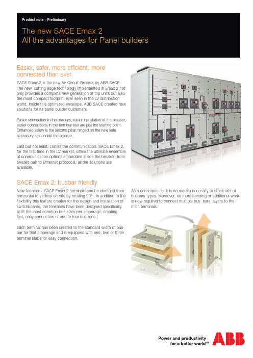
The new SACE Emax 2All the advantages for Panel buildersEasier, safer, more efficient, more connected than ever.SACE Emax 2 is the new Air Circuit-Breaker by ABB SACE. The new, cutting edge technology implemented in Emax 2 not only provides a complete new generation of trip units but also the most compact footprint ever seen in the LV distribution world. Inside this optimized envelope, ABB SACE created new solutions for its panel builder customers.Easier connection to the busbars, easier installation of the breaker, easier connections in the terminal box are just the starting point. Enhanced safety is the second pillar, hinged on the new safe accessory area inside the breaker.Last but not least, comes the communication. SACE Emax 2, for the first time in the LV market, offers the ultimate ensemble of communication options embedded inside the breaker; from twisted pair to Ethernet protocols, all the solutions are available.SACE Emax 2: busbar friendlyNew terminals. SACE Emax 2 terminals can be changed from horizontal to vertical on-site by rotating 90°. In addition to the flexibility this feature creates for the design and installation of switchboards, the terminals have been designed specifically to fit the most common bus sizes per amperage, creating fast, easy connection of one to four bus runs.Each terminal has been created to the standard width of bus-bar for that amperage and is equipped with one, two or three terminal stabs for easy connection.As a consequence, it is no more a necessity to stock lots of busbars types. Moreover, no more bending or additional work is now required to connect multiple bus bars layers to the main terminals.2 The new SACE Emax 2: all the advantages for Panelbuilders | ABBThe new SACE Emax 2All the advantages for Panel buildersBreaker In Emax Emax 2Column nr Column Width:with Emax Column Width:with Emax 2Buscompartments QF12500E3 3P E2.2 3P 1600 mm400 mm300 mmQF22500E3 3P E2.2 3P QF31600E1 3P E1.2 3P QF42500E3 3P E2.2 3P 2800 mm 600 mm 300 mmQS12500E3 MS 3P E2.2 MS 3P QS21600E1 MS 3PE1.2 MS 3PSketch of the power distribution section of a Mall: two transformers in parallel, bus tie, GenSet.SACE Emax 2: more efficient−Smaller footprint −Less copper −Less steelSavings on copper are due to both reduction of footprint and reduction of power losses.Saving on copper:Busbar lenght -20%; Busbar section -8%.W= 2000 mm with EmaxW= 1600 mm with Emax 2ABB | The new SACE Emax 2: all the advantages for Panelbuilders 3SACE Emax 2: more connected−Every Emax 2 circuit breaker can be equipped with mul-tiple cartridge-type communication modules that can be easily installed directly on the terminal box at any time. The communication units allow the circuit breakers to be integrated into all automation and energy management systems through the use of Modbus, Profibus and Device-net protocols as well as the modern Modbus TCP , Profinet and Ethernet IP protocols. Emax 2’s communication abili-ties eliminate the need for costly and difficult conversion components. −With the new terminal box with spring clamps , cabling has never been so easy: no tools are required for the connec-tion.SACE Emax 2: safer−Safe accessory installation. Removal of the main Emax 2 cover allows access to the accessory area only, not to the area containing the operating mechanism. This feature pro-vides additional safety, both to maintenance personnel and tothe possibility of damaging the breaker itself. The operatingmechanism can still be accessed for maintenance by remov-ing an internal series of protective covers.−Locking shutters. Shutters on the fixed part of withdrawable circuit breakers can be locked from the front, without access through the inside of the fixed part, so the moving breaker does not need to be taken out in order for locking to occur. In addition the upper and lower shutters are independent of each other for simplified, safe maintenance activitiesSACE Emax 2: easier−Ease of installation. Dedicated guide rails simplify move-ment and allow correct and locked positioning from“racked-out” to “test” to “racked-in”. In addition, the guide rails extend outside the fixed part so that the mobile part can be easily installed by setting it into the rails using a crane or lift. This allows easy and safe installation −Easy to upgrade. The characteristics of Emax 2 permit an easy substitution of the Emax in the switchboards already certified according to IEC61439-2 without retesting them. The requirements for what concern device substitutions (paragraph 10.10.3.5 and table 13 of the IEC61439-1) are fulfilled.−Neutral pole flexibility. The neutral position for Emax 2 circuit breakers can be modified directly from the trip unit to change from N, L1, L2, L3 to L1, L2, L3, N. −Ease to segregate . Special spacing along the fixed part allows the insertion of insulating separators , simplifying theimplementation of the different segregation forms.For more information please contact: ABB SACEA division of ABB S.p.A.L.V. BreakersVia Baioni, 3524123 Bergamo - ItalyTel.: +39 035 395 111 Fax: +39 035 395306-433 1 S D C 2 0 0 0 2 8 B 0 2 0 1 -1 1 / 2 0 1 2。
ABB E开关
E1B800 R800 PR122/P-LSI FHR NST 42
E1B800 R800 PR122/P-LSIG FHR NST 42
E1B800 R800 PR123/P-LSI FHR NST 42
E1B800 R800 PR123/P-LSIG FHR NST 42
E3V3200 R3200
E4V3200 R2000
E4V3200 R3200
E4V4000 R2000
E4V4000 R4000
E6V3200 R3200
E6V4000 R4000, R3200
E6V5000 R3200
E6V5000 R5000
E6V6300 R3200
E6V6300 R6300
E2B1600 R1600, R800, R630, R400
E2B2000 R2000, R1250, R800
E1N800 R800, R630, R400
E1N1000 R1000, R800, R400
E1N1250 R1250, R800, R400
E1N1600 R1600, R800, R400
E2N1000 R1000, R800, R400
E2N1250 R1250, R1000, R800, R400
E2N1600 R1600, R800, R400
E2N2000 R2000, R1250, R800
E3N2500 R1600
E3N2500 R2500
E3N3200 R2000
E1B800 R630 PR123/P-LSI FHR NST 42
ABBEmax系列框架式断路器储能故障分析与应对措施
( 2 )开 关的操 作频率低 。根据生 产厂家 的建议 ,对 于操作 频率较低或者平时不进行操 作 的 开 关 , 需要 定 期 对 其 进 行 切 换 操 作 , 以改 善操作机构 的润滑环境 ,防止久不操作的开关 机构 内部发生粘连 。而 实际上,在机组运行较 为稳定 的前提 下,配电系统的开关是较少进行 切换 的。 ( 3 )维 护 周 期 过 长 。 在 机 组 稳 定 运 行 的 前提下 ,低压配 电开关 的停运机会较少,部分 开关 的维护无法做 到每 年一次,储能机构的润 滑环境恶化而致故 障。 ( 4 )设备 特性 。从老 款 E ma x开关开 始 便 曾出现 开关 操作 机 构循环 储 能并释 放 的情 况 , 针 对 Ne w E ma x系 列 开 关 , A BB对 主 驱 动轴两端轴承支撑 部位 进行了焊点加强,但该 手段仅仅是增加 了弹簧释放能量时驱动轴的抗 冲击强度 ,并不 能从 根本上解 决循环储能的 问 题。通过对某进 口品牌 同类型断路器进行拆解 发现 ,其各转轴 的回位 弹簧材质及强度 明显优 于 AB B,回位弹 簧 的强度 与转轴 的润滑 效果 直接 决定 了转轴 的工作效率。 ( 5 ) 开 关 设 计 缺 陷 。E ma x开 关 采 用 的 是合 闸后储 能的方式,通过合 闸半轴 的回位时 间和机构储 能时间的配合来完成储能 。实践表 明,一旦合 闸半轴两端摩擦力偏大或者半轴上 的挂钩稍微 存在 位置偏差,则有可能开关储能 已完成时合 闸半轴 还未回到位。这说明该型开 关在此设计上欠缺 配合 的裕量。另外 ,一旦合 闸 半 轴 被 卡 住 ,相 当 于 合 闸 按 钮 一 直 处 于 被 按 下 的状态 ,那么在 电动储能的情况下 ,运行人 员在远方操作开 关时,开关会一直循环储能和 释放 的过程 ,且无法对 开关进行分闸。只能手 动 断 掉 储 能 电源 后 方 能 分 开 开 关 。 这 样 的 设 计 缺陷与 “ 故 障情况 下分 闸优先于合闸 ”的常规 理念不符 ,对低压配 电造成很大 的隐患。
ABB Emax电源电路保护器说明书

16Em a x P ow e r b r e a k e rs16Emax power breakersABB’s Emax series of low voltage power circuit breakers embodies over half a century’s experience and technological development in power circuit breakers.The Emax offers a series of breakers that is totally innovative in its technological design, ease of installation and use, making it the ideal solution for the growing requirements of designers, switchboard and switchgear manufacturers, installers, OEMs and users.The Emax power circuit breakers are UL Listed and meet the ANSI Standard for low voltage power circuit breakers.ABB Emax power circuit breakers are available in fi ve different models (four sizes) with rated continuous current from 800A to 5000A and rated short-circuit current range from 42kA to 125kA (480V).Technical catalog 1SDC200003 D0201 is available upon request.BCS Switchgear Inc.Switchgear | Circuit Breakers | Parts | Tech SupportE1 E2 E3E4 E6E6Specifi cations common to the entire rangeRated max voltage 635VACRated voltage 600VACTest voltage (1min 50/60Hz) 2.2kVFrequency 50-60HzNumber of poles 3/4Versions Fixed/DrawoutE 1 S 16 X X X X X X X X X XAccessories: X = noneA = mechanical counter F = A & BB = button guardAccessories: X = none G = A & C Q = B & EA = mechanical trip indicator H = A & D R =B & FB = mechanical trip indicator J = A & E S = B,C & E& bell alarm K = A & F T = B, C & FC = padlock provision (open) L = A, C & E U = C & ED = keylock (open) M = A, C & F V = C & FE = position lock N = B & C W = D & EF = access pos. lock P = B & D Y = D & FUndervoltage trip:0 = none50/60Hz & VDC: A = 24VDC B = 30VC=48VD=60VE = 110 – 120VF = 125 – 127VG=220–240VH=250VJ = 380 – 400VAC K = 440 – 480VACSecond shunt trip: L = 24VDC M = 30VN=48VP=60VQ = 110 – 120V R = 125 – 127VS=220–240VT=250VU = 380 – 400VAC V = 440 – 480VAC1Will be shipped separately.2For withdrawable breakers, use "H".3Not available with PR112 trip units. External 15A auxiliary kit can be used.Shunt trip: 0 = none50/60Hz & VDC: A = 24VDC, B = 30V, C = 48V, D = 60V,E = 110 – 120V,F = 125 – 127V,G = 220 – 240V,H = 250V,J = 380 – 400VAC, K = 440 – 480VACSpring charging motor: (includes spring charged signal, P/N does not show)0 = none, A = 24 – 30VAC/VDC, B = 48 – 60VAC/VDC, C = 110-130VAC/VDC,D = 220 – 250VAC/VDC,E = spring charged signal onlyContacts:A = 4 auxB = 10 auxC = 15 auxD = UV energ. N.O.E = UV energ.NCF = A & DG = A & EH = B & DJ = B & E K = C & D L = C & EClosing coil: 0 = none50/60Hz & VDC: A = 24VDC, B = 30, C = 48, D = 60, E = 110 – 120, F = 125 – 127, G = 220– 240, H = 250, J = 380 – 400VAC, K = 440 – 480VACTerminal types: (1st letter is upper terminal, 2nd letter is lower terminal)H = rear horz 2., V = rear vert. 1H = HH, V = VVA = HV,B = VHTrip unit: A = PR111/P, LI B = PR111/P, LSI C = PR111/P, LSIGD = non-automaticE = PR112/P, LSIF = PR112/P, LSIGG = PR112/PD, LSI H = PR112/PD, LSIG N = PR113/PP = PR113/PDVersion: B = fi xed breaker, UL; D = withdrawable breaker, UL, less cradleMax. ampere rating: 02 = 250, 04 = 400, 08 = 800, 10 = 1000, 12 = 1200, 16 = 1600, 20 = 2000, 25 = 2500, 32 = 3200,36 = 3600, 40 = 4000, 50 = 5000Breaking capacity: B = basic, N = normal, S = standard, H = high, V = very highFrame size: 1 = 1, 3P; 2 = 2, 3P; 3 = 3, 3P; 4 = 4, 3P; 6 = 6, 3P; A = 1, 4P; B = 2, 4P, C = 3, 4P; D = 4, 4P; F = 6, 4PE 1 X 12 X X XAccessories : X = none A = Shutter padlockContacts : 0 = none, A = 5 position auxiliaries B = 10 position auxiliariesVersion : K = cradle, ULV = cradle for E3VMax. ampere rating : UL: 12 = 1200 (E1); 16 = 1600 (E2); 20 = 2000 (E3); 25 = 2500 (E3); 36 = 3600 (E4); 50 = 5000 (E6)Frame size : 1 = 1, 3P; 2 = 2, 3P; 3 = 3, 3P; 4 = 4, 3P; 6 = 6, 3P; A = 1, 4P; B = 2, 4P; C = 3, 4P; D = 4, 4P; F = 6, 4PTerminal types :(1st letter is upper terminal, 2nd letter is lower terminal) H = rear horz., V = rear vert. H = HH, V = VV A = HV , B = VHGeneral informationStandard featuresNOTE: Switches provided standard without 4 auxiliary contacts.Standard features – manually operated UL breaker • Rear horizontal terminals• PR111 trip unit with LI protection functions• Manual mechanical close and open pushbuttons• CB open/closed mechanical indicator• Spring charged/discharged mechanical indicator• 2NO & 2NC auxiliary contacts for open/closed position indication • Lifting plates• Current transformers• Terminal boxFixed breakersFixed breakersStandard features – manually operated UL breaker• Rear horizontal terminals• PR111 trip unit with LI protection functions• Manual mechanical close and open pushbuttons • CB open/closed mechanical indicator• Spring charged/discharged mechanical indicator• 2NO & 2NC auxiliary contacts for open/closed position indication • Lifting plates • Current transformers • Terminal boxNeutral pole rating• E1 – E3 = 100% rating• E4 – E6 = 50% ratingWithdrawable breakersStandard features – electrically operated breakerMoving part• PR111 trip unit with LI protection feature• Spring charging motor• Shunt trip• Closing coil• Manual mechanical close and open pushbuttons• CB open/closed mechanical indicator• Spring charged/discharged mechanical indicator• 2NO & 2NC auxiliary contacts for open-closed position indication• Lifting plates• Current transformers• Racking device with closed door• Circuit breaker racking position indicator• Sliding contacts• Fail safe device (not available with YU)Standard features – electrically operated breakerFixed part• Safety shutters• Rear horizontal terminals• Sliding contacts• Anti-insertion lock• Ground connectionWithdrawable breakersStandard features – electrically operated breaker Moving part• PR111 trip unit with LI protection feature • Spring charging motor • Shunt trip • Closing coil• Manual mechanical close and open pushbuttons • CB open/closed mechanical indicator• Spring charged/discharged mechanical indicator• 2NO & 2NC auxiliary contacts for open-closed position indication • Lifting plates • Current transformers• Racking device with closed door• Circuit breaker racking position indicator • Sliding contacts• Fail safe device (not available with YU)Standard features – electrically operated breaker Fixed part• Safety shutters • Rear horizontal terminals • Sliding contacts • Anti-insertion lock • Ground connectionNeutral pole rating• E1 – E3 = 100% rating • E4 – E6 = 50% ratingStandard features – manually operated UL switch • Rear horizontal terminals• Manual mechanical close and open pushbuttons• CB open/closed mechanical indicator• Spring charged/discharged mechanical indicator• Lifting plates• Terminal boxFixed switchesStandard features – manually operated UL switch• Rear horizontal terminals• Manual mechanical close and open pushbuttons • CB open/closed mechanical indicator• Spring charged/discharged mechanical indicator • Lifting plates • Terminal boxFixed switchesNeutral pole rating• E1 – E3 = 100% rating• E4 – E6 = 50% ratingStandard features – manually operated switchFixed part• Safety shutters• Rear horizontal terminals• Sliding contacts• Anti-insertion lock• Ground connectionWithdrawable switchesStandard features – manually operated switchMoving part• Manual mechanical close and open pushbuttons• Circuit breaker open/closed mechanical indicator• Spring charged/discharged mechanical indicator• Lifting plates• Racking device with closed door• Circuit breaker racking position indicator• Sliding contacts• Fail-safe device (not available with YU)Standard features – manually operated switches Fixed part• Safety shutters • Rear horizontal terminals • Sliding contacts • Anti-insertion lock • Ground connectionNeutral pole rating• E1 – E3 = 100% rating • E4 – E6 = 50% ratingWithdrawable switchesStandard features – manually operated switch Moving part• Manual mechanical close and open pushbuttons • Circuit breaker open/closed mechanical indicator • Spring charged/discharged mechanical indicator • Lifting plates• Racking device with closed door• Circuit breaker racking position indicator • Sliding contacts• Fail-safe device (not available with YU)1 Without intentional delays.2 Consult factory for drawings.E1 E2 E3 E4Specifi cations common to the entire rangeVoltagesRated service voltage Ue 690~ / 250– VRated insulation voltage Ui 1000 VRated impulse withstand voltage Uimp 12 kVService temperature -5 …+70 °CStorage temperature -40 …+70 °CHzFrequency f50–60Number of poles 3–4Versions Fixed / WithdrawableE6Circuit breaker type1Without intentional delays.2Consult factory for drawings.E 1 S 16 X X X X X X X X X XAccessories: X = noneA = mechanical counter F = A & BB = button guardAccessories: X = none G = A & C Q = B & EA = mechanical trip indicator H = A & D R =B & FB = mechanical trip indicator J = A & E S = B,C & E& bell alarm K = A & F T = B, C & FC = padlock provision (open) L = A, C & E U = C & ED = keylock (open) M = A, C & F V = C & FE = position lock N = B & C W = D & EF = access pos. lock P = B & D Y = D & FUndervoltage trip:0 = none50/60Hz & VDC: A = 24VDC B = 30VC=48VD=60VE = 110 – 120VF = 125 – 127VG=220–240VH=250VJ = 380 – 400VAC K = 440 – 480VACSecond shunt trip: L = 24VDC M = 30VN=48VP=60VQ = 110 – 120V R = 125 – 127VS=220–240VT=250VU = 380 – 400VAC V = 440 – 480VACShunt trip: 0 = none50/60Hz & VDC: A = 24VDC, B = 30, C = 48, D = 60, E = 110 – 120,F = 120 – 127,G = 220 – 240,H = 240 - 250, J = 380 – 400VAC,K = 440 – 480VACSpring charging motor: (includes spring charged signal, P/N does not show)0 = none, A = 24 – 30VAC/VDC, B = 48 – 60VAC/VDC, C = 110-130VAC/VDC,D = 220 – 250VAC/VDC,E = spring charged signal onlyClosing coil: 0 = none50/60Hz & VDC: A = 24VDC, B = 30, C = 48, D = 60, E = 110 – 120, F = 120 – 127,G = 220 – 240, H = 240 - 250, J = 380 – 400VAC, K = 440 – 480VACTerminal types: (Ist letter is upper terminal, 2nd letter is lower terminal) 1H = rear horz., V = rear vert., F = front, L = rear fl atH = HH, V = VV, F = FF, L = LL,A = HV,B = VH,C = HF,D = FH,E = HL, G = LH, J = VF, K = FV, M = VL, N = LV,P = FL, Q = LFVersion: F = fi xed breaker, IEC; W = withdrawable breaker, IEC, less cradleMax. ampere rating: 02 = 250, 04 = 400, 08 = 800, 10 = 1000, 12 = 1250, 16 = 1600, 20 = 2000, 25 = 2500, 32 = 3200,40 = 4000, 50 = 5000, 63 = 6300Breaking capacity: B = basic, N = normal, S = standard, H = high, V = very high, L = limitingFrame size: 1 = 1, 3P; 2 = 2, 3P; 3 = 3, 3P; 4 = 4, 3P; 6 = 6, 3P; A = 1, 4P; B = 2, 4P; C = 3, 4P; D = 4, 4P; F = 6, 4P1 For withdrawable breakers, use "H".2Not available with PR112 trip units; use external 15 auxiliary kit.Trip unit: A = PR111/P, LI B = PR111/P, LSI C = PR111/P, LSIGD = non-automaticE = PR112/P, LSIF = PR112/P, LSIGG = PR112/PD, LSI H = PR112/PD, LSIG N = PR113/PP = PR113/PDContacts:A = 4 auxB = 10 auxC = 15 auxD = UV energ. N.O.E = UV energ.NCF = A & DG = A & EH = B & DJ = B & E K = C & D L = C & EE 1 X 12 X X XAccessories : X = none A = Shutter padlockContacts : 0 = none A = 5 position auxiliaries B = 10 position auxiliariesVersion : C = cradle, IECMax. ampere rating : IEC: 12 = 1250 (E1); 20 = 2000 (E2); 32 = 3200 (E3); 40 = 4000 (E4); 63 = 6300 (E6)Frame size :1 = 1, 3P;2 = 2, 3P;3 = 3, 3P;4 = 4, 3P; 6 = 6, 3P A = 1, 4P; B = 2, 4P; C = 3, 4P; D = 4, 4P; F = 6, 4PTerminal types :(Ist letter is upper terminal, 2nd letter is lower terminal.) H = rear horz., V = rear vert., F = front, L = rear fl at H = HH, V = VV , F = FF , L = LL,A = HV ,B = VH,C = HF ,D = FH,E = HL, G = LH, J = VF , K = FV , M = VL, N = LV , P = FL, Q = LFGeneral informationStandard featuresNOTE: Switches provided standard without 4 auxiliary contacts.Fixed breakersStandard features – manually operated breaker Fixed breaker• Rear horizontal terminals• PR111 trip unit with LI protection functions• Manual mechanical close and open pushbuttons• CB open/closed mechanical indicator• Spring charged/discharged mechanical indicator• 2NO & 2NC auxiliary contacts for open-closed position indication • Lifting plates• Current transformers• Terminal boxFixed breakersStandard features – manually operated breaker Fixed breaker• Rear horizontal terminals• PR111 trip unit with LI protection functions• Manual mechanical close and open pushbuttons • CB open/closed mechanical indicator• Spring charged/discharged mechanical indicator• 2NO & 2NC auxiliary contacts for open-closed position indication • Lifting plates • Current transformers • Terminal boxNeutral pole rating• E1 – E3 = 100% rating• E4 – E6 = 50% rating 11 Consult factory for special 100% neutral pole rating.Standard features – electrically operated breakerMoving part• PR111 trip unit with LI protection functions• Spring charging motor• Shunt trip• Closing coil• Manual mechanical close and open pushbuttons• CB open/closed mechanical indicator• Spring charged/discharged mechanical indicator• 2NO & 2NC auxiliary contacts for open-closed position indication• Lifting plates• Current transformers• Racking device with closed door• Circuit breaker racking position indicator• Sliding contactsWithdrawable breakersStandard features – electrically operated breakerFixed part• Safety shutters• Rear horizontal terminals• Sliding contacts• Anti-insertion lock• Ground connectionStandard features – electrically operated breaker Moving part• PR111 trip unit with LI protection functions • Spring charging motor • Shunt trip • Closing coil• Manual mechanical close and open pushbuttons • CB open/closed mechanical indicator• Spring charged/discharged mechanical indicator• 2NO & 2NC auxiliary contacts for open-closed position indication • Lifting plates • Current transformers• Racking device with closed door• Circuit breaker racking position indicator • Sliding contactsWithdrawable breakersStandard features – electrically operated breakerFixed part• Safety shutters • Rear horizontal terminals • Sliding contacts • Anti-insertion lock • Ground connectionNeutral pole rating• E1 – E3 = 100% rating • E4 – E6 = 50% rating 11 Consult factory for special 100% neutral pole rating.Fixed switches, 3 poleStandard features – manually operated switch • Rear horizontal terminals• Manual mechanical close and open pushbuttons• Circuit breaker open/closed mechanical indicator• Spring charged/discharged mechanical indicator• Lifting plates• Terminal boxFixed switches, 4 poleStandard features – manually operated switch• Rear horizontal terminals• Manual mechanical close and open pushbuttons • Circuit breaker open/closed mechanical indicator • Spring charged/discharged mechanical indicator • Lifting plates • Terminal boxNeutral pole rating• E1 – E3 = 100% rating• E4 – E6 = 50% rating 11 Consult factory for special 100% neutral pole rating.Withdrawable switches, 3 poleStandard features – manually operated switchMoving part• Manual mechanical close and open pushbuttons• Circuit breaker open/closed mechanical indicator• Spring charged/discharged mechanical indicator• Lifting plates• Racking device with closed door• Circuit breaker racking position indicator• Sliding contactsStandard features – manually operated switchFixed part• Safety shutters• Rear horizontal terminals• Sliding contacts• Anti-insertion lock• Ground connectionWithdrawable switches, 4 poleStandard features – manually operated switch Moving part• Manual mechanical close and open pushbuttons • Circuit breaker open/closed mechanical indicator • Spring charged/discharged mechanical indicator • Lifting plates• Racking device with closed door• Circuit breaker racking position indicator • Sliding contactsStandard features – manually operated switchFixed part• Safety shutters • Rear horizontal terminals • Sliding contacts • Anti-insertion lock • Ground connectionNeutral pole rating• E1 – E3 = 100% rating • E4 – E6 = 50% rating 11 Consult factory for special 100% neutral pole rating.1Order as alternative to UV trip.1Order as alternative to various types of interlock and kirk key lock. For mounting on fi xed breaker, also requires accessory 32 (KE6MLP).1Keylock number when factory installed is N3004222. 2Also requires position lock (accessory 29).36a. Neutral current transformer (required for 4 wire ground fault systems)1 IEC only.37. Mechanical interlocks (base plate for fi xed circuit breaker)38. Interlock for fi xed circuit breaker/fi xed part of withdrawable circuit breaker (cable attachment plate)39. Interlock for fi xed circuit breaker/moving part of withdrawable circuit breaker (internal interlocking shaft)1Order as an alternative to the Accessory number 15 auxiliary contact (see page 16.27) and kirk key lock.41. Electronic time delay for undervoltage release 143. Kirk key lock adaptor plate (in open position) 244. Kit for converting fi xed breaker with rear horizontal terminals to rear vertical (set of three terminals)1 IEC only.2Kirk key not provided. Order as an alternative to the various types of interlocks and auxiliary contacts (see Accessory 26c and 26d on page 16.27).Part."Z"。
ABB低压产品介绍

產品一覽產品一覽ABB的始創人查理.布朗(Charles Brown)瑞士BBC Brown Boveri&Cie公司與瑞典的ASEA公司正式合並成為ABB公司產品一覽ABB在中國2產品一覽3產品一覽產品一覽ABB低壓產品一覽斷路器空氣斷路器(EmaxABB公司為配合先進工程技術的需求,完成了對新型低壓空氣斷路器械性、電氣性及熱應力具有更高的抗力。
Emax空氣斷路器提供的邏輯功能元件可與ABB其它低壓產品整合及協調。
Emax空氣斷路器共有五種不同的型號:E1、E2、E3、E4(即具有不同分斷及額定電流容量的部份)新型Emax空氣斷路器的分斷能力比以前系列產品有所提高,範圍由空氣斷路器的其它主要優點如下:•尺寸小•對系列產品而言,具有同樣的高度、深度及附件•可應用於交流(a.c.)•可共用組件,例如相同的開 與閉合的釋放裝置是相同的秉承ABB產品的優良傳統,Emax位居同類產品領先地位。
空氣斷路器(MegamaxMegamax空氣斷路器設有PR1微處理機或AR1模擬固態交流,EG電磁直流過電流釋放機構等選擇性保護器,裝配有電子控制設計和接口裝置,可配對話單元,可與中央管理系統連接作數据傳輸遙控及不同類型的接口和附件,因而特產品一覽斷路器工控產品產品一覽工控產品產品一覽開關類產品產品一覽線路保護裝置微型斷路器(S260、S250S、S270、S280、S290、S9)ABB針對一般用途的微型斷路器而創造了高性能外殼材料和具有一體化動作機芯,從而實現了全方位保護,保証了電產品一覽線路保護裝置開關插座10產品一覽箱體終端配電箱(ACM、ACP、ACF)ACM、ACP、ACF智能建築控制系統電網質量產品12低壓系統ABB MD190(Honor)"安亞"組合型開關櫃MNS開關櫃ArTu®K開關櫃低壓產品及系統適用於各種場合ABB的產品符合國家及國際標準,同時也能夠因應各種服務而提供特別的功能,並且作出全面的技術支援。
- 1、下载文档前请自行甄别文档内容的完整性,平台不提供额外的编辑、内容补充、找答案等附加服务。
- 2、"仅部分预览"的文档,不可在线预览部分如存在完整性等问题,可反馈申请退款(可完整预览的文档不适用该条件!)。
- 3、如文档侵犯您的权益,请联系客服反馈,我们会尽快为您处理(人工客服工作时间:9:00-18:30)。
"电流 ( 相电流,中性线电流,接 地故障电流) "电压 ( 相电压,线电压,剩余电压) "功率 ( 有功功率,无功功率,视 在功率) "功率因数 "频率及峰值系数 " 能量(有用功,无用功,视在 功,表计) " 谐 波 (高 达 40 次 谐 波 ) (PRl23 only) ! 通 信 劝 能 : ( PRl22-
2005年第 24 卷第 2 期
!"
!"#$ !ABB 新 Emax E 系列低压空气断路器
市
全新的智能化脱扣器采用最 新的科技, 传统的脱扣器采用单个 的 CPU 对保护、测量及通信进行管 理。 而 Emax E 新脱扣器采用 CPU 及 PSD 双微处理器技术,该 DSP 集 成了一个 5l2KB 的 flash 存储器和 一个 256KB 的 flash 存储器以及丰 富的可编程 I/O 口, 还可实现在系 统中编程 ( ISP)以及在应用中编程 IAP)等多种功能。 使用 DSP 可完 ( 全满足系统的各种要求, 而且节省 空间, 大量减少分立元件和总线的 数量,使用和配置更加灵活,增加了 整个系统的稳定性和可靠性。 基于 Mocbus 通信协议的对话 单元,可与 ABB EP0l0 现场总线适 配器进行连接, 实现与不同网络之 间的通信,如 Profibus 和 Devicenet. 全系列产品具有标准化的尺 寸, 无论是固定式断路器还是抽出 式断路器, 它们都具有相同的高度 及深度。 具有完全模块化的完善的 附件系列,并且附件全系列通用。 Emax E 系列低压空气断路器 共 分 为 五 种 规 格( El,E2,E3,E4, E6), 四 种 外 形 尺 寸( El,E2 外 形 尺寸相同)。 主要电气特性如下表 所示:
如图 2 所示的中压及低压系统 中,低压侧的短路有可能会引起变 压器上游的中压开关跳闸,因为中 压开关与低压开关对短路的反应电 流和反应时间的要求是不同的。 如图 S 所示,低压侧主断路器 的特性曲线与中压开关特性曲线之 间形成交叉,在低压侧出现短路故 障时有可能引越级跳闸。 如图 4 所示,如果在低压测的 S”保护,可 主断路器中设置双重 “ 防止越级跳闸的产生。 其中, “ 低”
E2 E3 690 E4 E6
PRl23+PRl20/D-M) "基于 Mocbus RTU 协议, 物理 层为 RS一485,速率为 l9200 b/s " 通 过 现 场 总 线 适 配 器( ABB EP0l0-FBP), 可 与 Profibus-DP, Device net 及 AS-i 系统通信 " 应 用 ABB PRl20/D-BT 无 线 蓝牙模块,与实现 PRl22/PRl23 与 PDA 或手提电 脑 之间的无线蓝牙 通信 ! 数据劝能:从( PRl22,PRl23) 脱扣器上可获取取断路器的鲁种 参数: "断路器状态 ( 分,合) "抽出式断路器的位置 ( 摇进, 摇出) " 断路器的运行模式 (本机 , 遥控 ) "各种参数的设置 "负载控制参数 "同时,脱扣器上 还配置了一个 专业的数据日志记录仪, 在线路出 现故障时自动触发, 祥细记录故障 时段的电流及电压参数, 以便事后 分析故障的原因。
2OO5年第 24 卷第 2 期
"#
ABB新Emax E系列低压空气断路器
作者: 作者单位: 刊名: 英文刊名: 年,卷(期): 张启友 ABB(中国)有限公司 电气应用 ELECTROTECHNICAL APPLICATION 2005,24(2)
本文链接:/Periodical_dgjszz200502011.aspx
75~l50 75~l50 75~l00 75 l00~l50 l00~l25 l00 75~85
800~l600 800~2000 800~3200 3200~4000 3200~6300 42~l30 42~l30 42~65 42 65~l30 65~l30 65~86 65
PRl2l,PRl22,PRl23 智能化脱扣器
emax e 系列低压空气断路器
ABB 公司推出的新 Emax E 系列低压空气断路 器, 是 ABB 公司多年来致力于探索新的解决方案、以 及积累多年开发设计经验的结晶。 它配备最新的基于 工 程 重 组 的 全 新 电 子 学 原 理 的 脱 扣 器( PRIZI, PRIZZ,PRIZS)、 便 于 现 场 升 级 的 多 种 功 能 模 块 PRIZ0/K,PRIZ0/V,PRIZ0/D-M,PRIZ0/D-BT)、全新 ( 概念的用于改变断路器额定电流的额定电流插块、以 及基于双绕组技术的电流传感器 ( CT 及 Rogowski)。
图1
图4
!双 “ 短路短延时保护功能”
阈值的保护设置可与中压断路器的 设置相配合,变压器低压侧的断路 器需要 “ 高” 阈值保护设置是因为 低压测的冲击电流较大。 !双 “ 接地故障保护功能”
图5 图2
如图 5 所示,Emax E 新的脱扣 器可对出现的低压断路器电源侧和 负载侧的接地故障进行保护,当低 压断路器负载侧出现接地故障时, 低压断路器脱扣分闸,消除接地故 障;当接地故障出现在低压断路器 的电源侧时,低压断路器会发出报 警或脱扣信号给变压器一次侧断路 器 ( 中压断路器刻,由一次侧断路器 确定是否将接地故障消除。
PRl22,PRl23) "过载长延时脱扣保护 ( L) "短路短延时脱扣保护 ( S) "短路瞬时脱扣保护 ( I) "接地故障脱扣保护 ( G) ! 高 级 保 护 劝 能 :( PRl22, PRl23) "剩余电流脱扣保护 ( Rc) "相不平衡保护 ( U) "超温保护 ( OT) " S 及 G 功能的区域联锁选择 性保护功能 ( Zone) "欠压保护 ( UV) "过压保护 ( OV) "剩余电压保护 ( RV) "逆功率保护 ( RP)
ABB 新 Emax E 系列低压空气断路器
! !"#$
市
劝能模块
新 Emax E 系列低压空气断路 器配有多种便于现场升级用的功能 模块。 这些模块与脱扣器之间的连 接都是自动识别 - 即插即用, 无须 进行任何配置上的设置。
供电系统时,断路器 C 会启动第二 组保护参数,以便与主断路器 B 之 间仍然能实现选择性配合保护。
型号规格 额定电压 Ue (V) 额定电流 Iu (A) 额极限分断容量 @4l5Vac (kA) 额定运行分断容量 @4l5Vac (kA) 额定短时耐受电流 ( ls)(kA) 额定短时耐受电流 ( 3s)(kA) 42~50 42~50 42~50 36 El
具有以下功能: ! 基 本 保 护 劝 能 :( PRl2l,
!
着电力市场的发展, 低压断路器作用已不仅仅 是为线路或设备提供单纯的过载和短路保护,
而是为工程提供完善的管理方案, 断路器作为一套完 整管理方案一部分, 必须能够随用户的需要进行现场 配置,以便满足不同场合对断路器的不同需求,如实现 基本保护、高级保护、测量、记录、通信、配置及现场升 级等功能。 HMI)以及 断路器还必须具有良好的人机介面( 模块化的结构,以便安装及维护。
ABB Emax E 系列低压空气断 路器共配置三种脱扣器, 分别为, PRl2l、PRl22、PRl23。
"低频率保护 ( UF) "高频率保护 ( OF) "电流方向性保护 ( D) ( PRl23 only) ! 测 量 劝 能 :( PRl22+PRl20/V, PRl23)
"#
2005年第 24 卷第 2 期
图3
!Prl20/K:信号功能模块,远程 指示断路器的报警及脱扣信号 !Prl20/V:测量模块,实现一系 列的电压、电流、功率、频率、能量等 方面的电参数测量 !Prl20/D-M: 基于 Mocbus 协 议的通信模块:实现脱扣器与监控 系统之间的通信 !Prl20/D-BT:无线蓝牙通讯模 块,实现脱扣器与 PDA 或便携式电 脑之间的通信 "特别劝能的应用 新 Emax E 系列低压空气断路 器还具有以下方面的特别功能,这 些特别的功能在实际应用中具有特 殊的意义。 !保护参数的双组设置: Emax E 新的脱扣器 PRl2S 可 实现双组参数设置,应用在一些极 其特殊的条件下,可实现选择性配 合保护。 图 l 所示为双电源切换系 统,U 为正常电源,G 为应急发电 机。 在正常电网供电的情况下,下 级断种器 C ( 具有双组保护刻数设 置刻与主断路器 A 之间已实现选择 性配合保护;当供电被切换至应紧
