PowerFlex 750快速入门
750变频器调试操作步骤

当电缆插入变频器卡槽(只有PowerFlex 750系列变频器)底部附近或变频器底部(PowerFlex 7系列变频器)的DPI端口时的分配器电缆端口
3. 按下键,显示上一次查看的文件夹。
4. 使用向左键或向右键浏览PROPERTIES(属性)文件夹。
5. 使用向上键或向下键选择Adjust Contrast(调整对比度)。
3.按下键显示上一次查看的文件夹。
4.使用或键浏览DIAGNOSTIC(诊断)文件夹。
5.使用或键选择Device Version(设备版本)。
6.按下(Enter)键显示设备版本信息。
7. 使用或键浏览可用的硬件和固件信息。
8.按下ESC软按键,返回到之前的屏幕。
PowerFlex 750系列变频器有一种被称为CopyCat的功能,能够使一整套参数上载到HIM。参数集可以是变频器主机的或任何所连接的外部设备的。这些信息可作为备份或通过从HIM存储器下载而传送到其他变频器或外部设备中。此外,CopyCat功能可以删除已存储的参数集或很方便地将参数集重新命名。
c.按下 软按键,选择最上面一行的秒,并使用数字键输入正确的秒钟。
11.按下ESC软按键,返回到上一屏幕。
变频器主机以及每个与其连接的外围设备都有一个缺省的名称。您可以修改任何这些缺省名称,但是每个新的名称不能够超过16个字符的长度。
1.进入状态屏幕。
2. 使用或键浏览要修改名称的设备端口(例如:Port 00为变频器主机)。
4.使用或键浏览DEV PARAM设备参数(或HOST PARAM主机参数)文件夹。
5.使用或键选择Linear List(线性列表)。
6.按下(Enter)键显示设备上一次查看的参数或线性列表中的第一个参数。
PowerFlex 750-Series Power Jumpers说明书
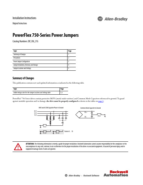
Installation InstructionsOriginal InstructionsPowerFlex 750-Series Power JumpersCatalog Numbers 20F, 20G, 21GSummary of ChangesThis publication contains new and updated information as indicated in the following table.PowerFlex® 750-Series drives contain protective MOVs (metal-oxide varistors) and Common Mode Capacitors referenced to ground. T o guard against unstable operation and/or damage, the drive must be properly configured as shown in the tables on page 3.Topic Page Summary of Changes 1Precautions2Power Jumper Configuration2Jumper Installation, Removal, and Storage 4Jumper Locations and Settings5Topic Page Added voltage code B to the Jumper Locations and Settings table5, 6ATTENTION: The following information is merely a guide for proper installation. Rockwell Automation cannot assume responsibility for the compliance or the noncompliance to any code, national, local or otherwise for the proper installation of this drive or associated equipment. A hazard of personal injury and/or equipment damage exists if codes are ignored.MOV and AC EMI Capacitor Phase to GroundCommon Mode Capacitor to Ground2Rockwell Automation Publication 750-IN011F-EN-P - June 2017PowerFlex 750-Series Power JumpersPrecautionsBefore proceeding, verify that all power to the drive has been removed.Qualified PersonnelPersonal SafetyProduct SafetyPower Jumper ConfigurationATTENTION: Allow only qualified personnel familiar with adjustable frequency AC drives and associated machinery to plan or implement the installation, start-up, and subsequent maintenance of the system. Failure to comply can result in personal injury and/or equipment damage.ATTENTION: To avoid an electric shock hazard, verify that the voltage on the bus capacitors has discharged completely before removing/installing jumpers. Frames 1 (7)Measure the DC bus voltage at the following points (see the PowerFlex 750-Series AC Drive Installation Instructions, publication 750-IN001 for locations):•Measure the DC bus voltage at the power terminal block by measuring between the +DC and -DC terminals or between the +DC and -DC test point sockets if equipped.•Also measure between the +DC terminal or test point and the chassis, and between the -DC terminal or test point and the chassis. The voltage must be zero for all three measurements.Frames 8 (10)Measure the DC bus voltage at the DC+ and DC- TESTPOINT sockets on the front of the power module (see Installation Instructions for location).ATTENTION: This drive contains ESD (Electrostatic Discharge) sensitive parts and assemblies. Static control precautions are required when installing, testing, servicing or repairing this assembly. Component damage can result if ESD control procedures are not followed. If you are not familiar with static controlprocedures, reference an applicable ESD protection guide.ATTENTION: Risk of equipment damage exists. The drive power source type must be accurately determined. Jumpers PE-A, PE-A1, PE-A2, and PE-B must be configured for the power source type according to the recommendations shown in the following table.Rockwell Automation Publication 750-IN011F-EN-P - June 20173PowerFlex 750-Series Power JumpersT o connect or disconnect these devices, refer to pages 5…7.In addition, on an ungrounded distribution system where the line-to-ground voltages on any phase could exceed 125% of the nominal line-to-line voltage, install an isolation transformer. See Wiring and Grounding Guidelines for PWM AC Drives, publication DRIVES-IN001, for more information on impedance grounded and ungrounded systems.Recommended Power Jumper Configurations – Frames 1 (7)Power Source Type Jumper PE-A (1) (2)(MOV / Input Filter Caps)(1)When MOVs are disconnected, the power system must have its own transient protection to maintain known and controlled voltages.(2)Frame 5…7 Common DC Input drives do not have the PE-A jumper.Jumper PE-B(DC Bus Common Mode Caps)Benefits of Correct Configuration on Power Source TypeNon-solid Ground •AC fed ungrounded •Impedance grounded • B phase ground •DC fed from an active converterDisconnected Disconnected Helps avoid severe equipment damage when ground fault occurs.Solid Ground•AC fed solidly grounded•DC fed from passive rectifier, which has a solidly grounded AC sourceConnected ConnectedReduced electrical noise, most stable operation, EMC compliance, reduced voltage stress on components and motor bearings.Recommended Power Jumper Configurations – Frames 8 (10)Power Source TypeJumper PE-A1 (1)(MOV)(1)When MOVs are disconnected, the power system must have its own transient protection to Achieve known and controlled voltages.Jumper PE-A2(Input Filter Caps)Jumper PE-B(DC Bus Common Mode Caps)Benefits of Correct Configuration on Power Source TypeNon-solid Ground •AC fed ungrounded•Impedance grounded• B phase ground•DC fed from an active converter Disconnected Disconnected Disconnected Helps avoid severe equipment damage when ground fault occurs.Solid Ground•AC fed solidly grounded•DC fed from passive rectifier, which has a solidly grounded AC sourceConnected Connected ConnectedReduced electrical noise, most stable operation, EMC compliance, reduced voltage stress on components and motor bearings.IMPORTANTCommon mode capacitors are used to conform with the EMC Directives. Removing these devices can withdraw the associated directive.4Rockwell Automation Publication 750-IN011F-EN-P - June 2017PowerFlex 750-Series Power JumpersJumper Installation, Removal, and StorageJumper screws (Frames 2…5), wires (Frames 1, 6 & 7), or plugs (Frames 8…10) are used to complete an electrical connection when installed/connected. When power jumper screws are not used, they are stored on the left interiorWhen installing a jumper screw or wire, note the recommended torque listed.Drive IdentificationThe ‘Voltage Code’ and ‘Default Power Jumper Configuration’ are on the drive nameplate. Use this information to perform the proper procedure in the following tables.ATTENTION: Hazard of equipment damage exists if jumpers are not properly disconnected. For Frames 2…5, completely remove the jumper screw from the circuit board.Frames 1, 6 & 7, secure the disconnected jumper wire to the standoff provided.Frames 8…10 drive assemblies, secure the disconnected jumper plug in the socket that is provided and verify that all drive assemblies are identically configured.Recommended Torque ValuesFrames Recommended Torque Recommended Screwdriver/Socket 1Not ApplicableNot Applicable2...5 1.36 N•m (12.0 lb•in) 0.14 N•m (1.2 lb•in) 6.4 mm (0.25 in.) flat or T15 Hexalobular 6 (7)1.36 N•m (12.0 lb•in)7 mm socket or T20 HexalobularPowerFlex 750-Series Power JumpersJumper Locations and SettingsThe following pages show jumper locations and settings.Jumper Locations and SettingsRockwell Automation Publication 750-IN011F-EN-P - June 20175PowerFlex 750-Series Power JumpersJumper Locations and Settings (Continued)6Rockwell Automation Publication 750-IN011F-EN-P - June 2017PowerFlex 750-Series Power Jumpers Jumper Locations and Settings (Continued)Rockwell Automation Publication 750-IN011F-EN-P - June 20177Allen-Bradley, PowerFlex, Rockwell Automation, and Rockwell Software are trademarks of Rockwell Automation, Inc.Trademarks not belonging to Rockwell Automation are property of their respective companies.Rockwell Otomasyon Ticaret A.Ş., Kar Plaza İş Merkezi E Blok Kat:6 34752 İçerenköy, İstanbul, T el: +90 (216) 5698400Rockwell Automation maintains current product environmental information on its website at/rockwellautomation/about-us/sustainability-ethics/product-environmental-compliance.page.Publication 750-IN011F-EN-P - June 2017Supersedes Publication 750-IN011E-EN-P - February 2014Copyright © 2017 Rockwell Automation, Inc. All rights reserved. Printed in the U.S.A.Rockwell Automation SupportUse the following resources to access support information.Documentation FeedbackY our comments will help us serve your documentation needs better. If you have any suggestions on how to improve this document, complete the How Are W e Doing? form at /idc/groups/literature/documents/du/ra-du002_-en-e.pdf .Technical Support CenterKnowledgebase Articles, How-to Videos, FAQs, Chat, User Forums, and Product Notification Updates.https:///Local Technical Support Phone Numbers Locate the phone number for your country./global/support/get-support-now.page Direct Dial Codes Find the Direct Dial Code for your product. Use the code to route your call directly to a technical support engineer./global/support/direct-dial.page Literature LibraryInstallation Instructions, Manuals, Brochures, and Technical Data./global/literature-library/overview.page Product Compatibility and Download Center (PCDC)Get help determining how products interact, check features and capabilities, and find associated firmware./global/support/pcdc.pageAdditional ResourcesThese documents contain additional information concerning related products from Rockwell Automation.Y ou can view or download publications at /literature/. T o order paper copies of technical documentation, contact your local Allen-Bradley distributor or Rockwell Automation sales representative.ResourceDescriptionPowerFlex 750-Series AC Drive Installation Instructions, 750-IN001.Provides the basic steps that are required to install a PowerFlex 750-Series AC drive.Wiring and Grounding Guidelines for Pulse Width Modulated (PWM) AC Drives,publication DRIVES-IN001.Provides basic information to properly wire, help protect, and ground pulse-width modulated (PWM) AC drives.Safety Guidelines for the Application, Installation, and Maintenance of Solid State Control, publication SGI-1.1.Provides general guidelines for the application, installation, and maintenance of solid-state control.Product Certifications website, .Provides declarations of conformity, certificates, and other certification details.。
PowerFlex 750-Series 控制节板远程安装套件指南说明书
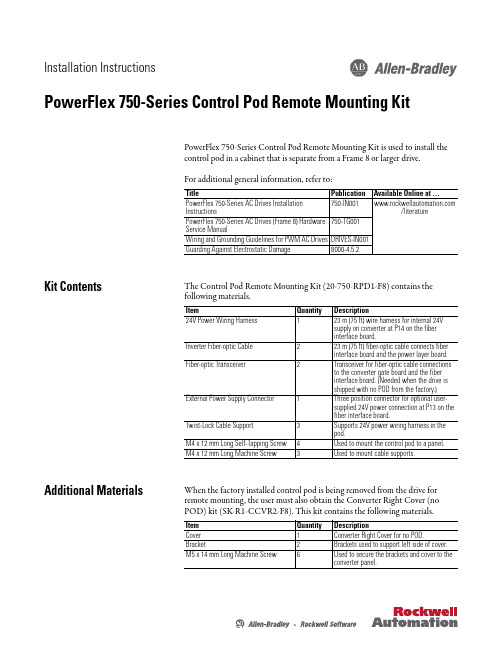
Installation InstructionsPowerFlex 750-Series Control Pod Remote Mounting Kit PowerFlex 750-Series Control Pod Remote Mounting Kit is used to install the control pod in a cabinet that is separate from a Frame 8 or larger drive.For additional general information, refer to:Kit ContentsThe Control Pod Remote Mounting Kit (20-750-RPD1-F8) contains the following materials.Additional Materials When the factory installed control pod is being removed from the drive forremote mounting, the user must also obtain the Converter Right Cover (noPOD) kit (SK-R1-CCVR2-F8). This kit contains the following materials.Title Publication Available Online at …PowerFlex 750-Series AC Drives Installation Instructions /literature PowerFlex 750-Series AC Drives (Frame 8) Hardware Service Manual 750-TG001Wiring and Grounding Guidelines for PWM AC Drives DRIVES-IN001Guarding Against Electrostatic Damage 8000-4.5.2Item Quantity Description 24V Power Wiring Harness 123 m (75 ft) wire harness for internal 24V supply on converter at P14 on the fiber interface board.Inverter Fiber-optic Cable 223 m (75 ft) fiber-optic cable connects fiber interface board and the power layer board.Fiber-optic Transceiver 2Transceiver for fiber-optic cable connections to the converter gate board and the fiber interface board. (Needed when the drive is shipped with no POD from the factory.)External Power Supply Connector 1Three position connector for optional user-supplied 24V power connection at P13 on the fiber interface board.Twist-Lock Cable Support 3Supports 24V power wiring harness in the pod.M4 x 12 mm Long Self-Tapping Screw 4Used to mount the control pod to a panel.M4 x 12 mm Long Machine Screw 3Used to mount cable supports.Item Quantity DescriptionCover 1Converter Right Cover for no POD.Bracket 2Brackets used to support left side of cover.M5 x 14 mm Long Machine Screw 6Used to secure the brackets and cover to theconverter panel.2PowerFlex 750-Series Control Pod Remote Mounting KitGeneral Precautions Read the following precautions before you begin working on the drive.Qualified PersonnelATTENTION: Only qualified personnel familiar with adjustable frequencyAC drives and associated machinery should plan or implement theinstallation, start-up and subsequent maintenance of the system. Failureto comply may result in personal injury and/or equipment damage.Personal SafetyATTENTION: To avoid an electric shock hazard, verify that the voltage onthe bus capacitors has discharged completely before servicing. Measurethe DC bus voltage at the -DC and +DC TESTPOINT sockets on the front ofthe power module (see Removing Power from the Drive on page4 forlocation).Product SafetyATTENTION: This drive contains ESD (Electrostatic Discharge) sensitiveparts and assemblies. Static control precautions are required wheninstalling, testing, servicing or repairing this assembly. Componentdamage may result if ESD control procedures are not followed. If you arenot familiar with static control procedures, reference Guarding AgainstElectrostatic Damage, publication 8000-4.5.2 or any other applicable ESDprotection handbook.Class 1 LED ProductATTENTION: Hazard of permanent eye damage exists when using opticaltransmission equipment. This product emits intense light and invisibleradiation. Do not look into module ports or fiber-optic cable connectors.PowerFlex 750-Series Control Pod Remote Mounting Kit3 Commonly Used Tools Service ToolsThis list covers the tools needed for kit installation.Fastener/Tool/Torque Information The disassembly illustrations in this publication identify the type of fastener, tool, and tightening torque used for disassembly/assembly of components in the drive:IMPORTANT Care must be taken to ensure that tools and/or hardware components do not fall into open drive assemblies. Do not energize the drive unless allloose tools and/or hardware components have been removed from thedrive assemblies and enclosure.Tool Description DetailsESD-protected place of work Working surface, Floor covering, seat and ground connections ESD-protective clothing Wrist wrap, shoes, overall clothing (coat)Multi meter Digital multi meter, capable of ac and dc voltage, continuity,resistance, capacitance measurements, and forward diode biastests. Fluke model 87 III or equivalent.Flat nose screw driver 5 mm (0.19 in.), 6.4 mm (0.25 in.)Hexalobular screw driver/bit#20, #25Phillips® screw driver/bit(1)(1)Phillips® is a registered trademark of the Phillips Screw Company.#2Torque wrench1...12 N•m (8.8…106 lb•in)Tool Type and Size:Px Phillips screw driver/bit and sizeTxx Hexalobular screw driver/bit and sizeFastener/Tool/Torque Information:4PowerFlex 750-Series Control Pod Remote Mounting KitRemoving Power from the Drive 1.Turn off and lock out input power. W ait five minutes.2.Verify that there is no voltage at the drive’s input power terminals.3.Measure the DC bus voltage at the -DC and +DC TESTPOINT socketson the front of the power module. ATTENTION: To avoid an electric shock hazard, verify that the voltage onthe bus capacitors has discharged completely before servicing. Measurethe DC bus voltage at the -DC and +DC TESTPOINT sockets on the front ofthe power module (see below for location).Remove power before making or breaking cable connections. When youremove or insert a cable connector with power applied, an electrical arc mayoccur. An electrical arc can cause personal injury or property damage by:•sending an erroneous signal to your system’s field devices, causingunintended machine motion•causing an explosion in a hazardous environmentElectrical arcing causes excessive wear to contacts on both the module andits mating connector. Worn contacts may create electrical resistance.PowerFlex 750-Series Control Pod Remote Mounting Kit5 Minimum Clearances The control pod must be mounted in a vertical orientation as shown and mustmake full contact with the mounting surface.•Do not use standoffs or spacers.•Inlet air temperature must not exceed 50 °C (122 °F).•Enclosure is rated IP00, NEMA/UL Open Type.6PowerFlex 750-Series Control Pod Remote Mounting KitApproximate Dimensions ArrayDimensions are in millimeters and (inches).PowerFlex 750-Series Control Pod Remote Mounting Kit7Remove Pod Assembly From Enclosure 1.Access the drive enclosure.2.Remove the control pod cover.3.Disconnect the factory installed internal 24V power supply cable fromP14 located on the fiber interface board.4.Disconnect the factory installed inverter fiber-optic cable from the P1(INV1) fiber-optic transceiver located on the fiber interface board. Description➊Internal 24V Power Connection Two point connector to P14.➋Inverter Fiber-optic Connection Fiber-optic cable to P1 fiber-optic transceiver INV1.8PowerFlex 750-Series Control Pod Remote Mounting Kit5.Loosen the captive screws on the back panel of the control pod until they6.Rotate the control pod to expose the hinge.7.Remove the four M4 x 12 mm screws that secure the control pod to theconverter control panel right side wall and remove the control pod. Ifdesired, the hinge can be removed from the control pod.PowerFlex 750-Series Control Pod Remote Mounting Kit9 8.Disconnect the factory installed internal 24V power supply cable fromconverter terminal block TB1 mounted on the converter control panelright side wall.9.Disconnect the factory installed inverter fiber-optic cable from the INVtransceiver located on the power layer interface board. Description➊Internal 24V Power Connection Three point connector disconnects from TB1 mounted onconverter control panel right side wall.➋Inverter Fiber-optic Connection Fiber-optic cable disconnects from INV fiber-optictransceiver on power layer interface board in card cage.10PowerFlex 750-Series Control Pod Remote Mounting KitMount and Wire the Control Pod When selecting a remote location for the control pod, note that the total length of each wiring harness provided is 23 m (75 ft).1.Drill 3.2 mm (0.13 in.) pilot holes in the control pod mounting surface.2.Mount the control pod using the four M4 x 12 mm self-tapping screwsprovided.PowerFlex 750-Series Control Pod Remote Mounting Kit 113.Connect the 23 m (75 ft) internal 24V power wire harness to P14 on thefiber interface board.4.Connect the 23 m (75 ft) inverter fiber-optic cable to P1 (INV1) on thefiber interface board.Fiber Interface Board Connections 5.Route the 23 m (75 ft) internal 24V power wire harness and inverter fiber-optic cable back to the drive enclosure.6.Install the three Twist-Lock cable supports in the positions shown onpage 12 using the M4 x 12 mm long machine screws supplied.No.Name Description ➊Internal 24V Power Connection Two point connector to P14.➋External 24V Power Connection Optional user-supplied power supply (1) connection to P13. (Three point connector supplied in kit.)(1)Refer to Optional External Power Supply on page 13, for power supply requirements and connection details.➌Inverter Fiber-optic Connection Fiber-optic cable connection to P1 fiber-optic cage INV1 onfiber interface board.IMPORTANT Minimum inside bend radius for fiber-optic cable is 25.4 mm(1 in.). Any bends with a shorter inside radius can permanentlydamage the fiber-optic cable. Signal attenuation increaseswith decreased inside bend radii.12PowerFlex 750-Series Control Pod Remote Mounting Kit7.Connect the internal 24V power connection to the converter terminalblock TB1 mounted on the converter control panel right side wall.8.Connect the inverter fiber-optic cable to the INV fiber-optic transceiveron the inverter power layer interface board. Description➊Internal 24V Power Connection Three point connector to converter terminal block TB1power supply connection.➋Inverter Fiber-optic Connection Fiber-optic cable connector to INV fiber-optic cage onpower layer interface board in card cage.➌Cable Supports Twist-Lock cable supports supplied.PowerFlex 750-Series Control Pod Remote Mounting Kit13Optional External Power SupplyConnect an optional external 24V power supply to P13 using the three positionconnector supplied.External Power Supply ConnectionsInstall Covers 1.Replace the control pod cover.14PowerFlex 750-Series Control Pod Remote Mounting Kit2.If the factory installed control pod was removed from the drive, install thesupport brackets provided in Converter Right Cover (no POD) kit (SK-R1-CCVR2-F8).3.Install the Converter Left Cover if removed.PowerFlex 750-Series Control Pod Remote Mounting Kit15 4.Install the Converter Right Cover (No POD) using the M5 x 14 mm longmachine screws supplied.U.S.Allen-BradleyDrivesTechnicalSupport-Tel:(1)262.512.8176,Fax:(1)262.512.2222,E-mail:*****************,Online: /support/abdrives*PN-124944*PN-124944Publication 750-IN015B-EN-P – September 2011Supersedes 750-IN015A-EN-P – August 2010Copyright © 2011 Rockwell Automation, Inc. All rights reserved. Printed in USA.。
AB PowerFlex750变频器需要设定参数

PowerFlex 755 参数含义 铭牌电压 铭牌电流 铭牌频率 铭牌转速
铭牌功率单位 铭牌功率 电机极数
电机控制类型 电压/赫兹曲线
自整定 自整定转矩
76
总惯量
设备名 图纸编号
水平电机
KW
6 3、感应电机磁通矢量控制
0、电压/赫兹 0、就绪 100%
2S 2S 876、端口0-端口6基准值
备注
铭牌电压 铭牌电流 铭牌频率 铭牌转速
KW/HP 铭牌功率
SEW伺服电机
自整定时用100% 惯量自整定后此值会变化,加上负 载后需手动更改此值(用整定后的 值带负载后会出现抖动或停不了的 做电机自整定时选为“1”(不选
1,动态整定和惯量自整定不过)。 自整定时35参数选择6
0.17
80
永磁电机配置
125
主速度反馈选择
135
位置反馈选择
300
速度装置
301
访问级别
305
电压等级
306
负载类型
308
方向模式
309
速度转矩位置模式A
370
停止模式A
372
母线调节模式A
382
动态制动电阻类型
383
动态制动外部电阻阻值
384
动态制动外部功率
385
动态制动外部脉冲功率
426
再生功率限制值
整定结束后恢复为“0”
PRB/HZ
编码器定位选择7(位置点到点)
电阻实际值 电阻实际功率
速度模式使用 速度模式使用 DEVICENET总线通讯
根据实际安装卡槽而定
PowerFlex755变频器 操作说明
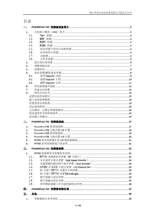
目录一、POWERFLEX 750 变频器面板简介 (3)1、人机接口模块(HIM)简介 (3)1.1、View 软键 (4)1.2、REF 软键 (4)1.3、EDIT 软键 (4)1.4、P AR# 软键 (4)1.5、状态屏幕下的语言切换软键 (4)1.6、启动和停止按键 (4)1.7、功能键 (4)1.8、文件夹按键 (5)2、复位到出场设置 (5)3、调整面板亮度 (7)4、设置时间 (8)5、备份参数/删除备份参数 (9)5.1、使用CopyCat功能 (9)5.2、创建CopyCat文档 (10)5.3、删除CopyCat文档 (11)6、带电拔插操作面板 (12)7、快速访问参数 (13)8、使用启动向导 (13)设置电机控制模式 (15)输入电机铭牌数据 (16)设置速度反馈装置 (18)设定速度限制 (20)方向测试、自整定和惯量测试 (20)组态速度参考和斜坡速率 (24)组态输入和输出 (25)二、POWERFLEX 750 变频器接线 (27)1、P OWER F LEX753典型接线图 (27)2、P OWER F LEX753主板内置I/O位置 (28)3、P OWER F LEX755典型接线图 (29)4、P OWER F LEX755主板内置I/O位置 (30)5、PF750系列变频器扩展I/O模拟量跳线 (31)6、PF750系列变频器端口的说明 (31)三、POWERFLEX 750 变频器参数 (32)1、PF750变频器常用参数简单说明 (32)1.1、PF750变频器常用参数(00号端口) (32)1.2、安全速度卡相关参数(Safe Speed Monitor) (34)1.3、双通道编码器反馈卡相关参数(Dual Encoder) (35)1.4、24VDC扩展I/O卡相关参数(I/O Module 24V) (35)1.5、13号端口PF755内置以太网参数 (35)1.6、14号端口PF750内置DeviceLogix (35)1.7、数字量输入组态举例 (35)1.8、数字量输出组态举例 (35)1.9、使用模拟量输入作为速度源组态举例 (36)四、POWERFLEX 750 变频器故障处理 (37)五、其他 (38)1、变频器相关参考资料 (38)附件一:POWERFLEX755变频器和POWERFLEX700变频器比较 (39)1.P OWER F LEX755和P OWER F LEX700电气性能比较 (39)2.P OWER F LEX755和P OWER F LEX700功能比较 (40)3.P OWER F LEX755和P OWER F LEX700外形尺寸比较 (40)4.P OWER F LEX755和P OWER F LEX700接线图的比较 (41)5.P OWER F LEX755和P OWER F LEX700参数的比较 (43)一、PowerFlex 750 变频器面板简介1、人机接口模块(HIM)简介下图显示了20-HIM-A6面板的按键。
PowerFlex750变频器简介相关资源简单故障
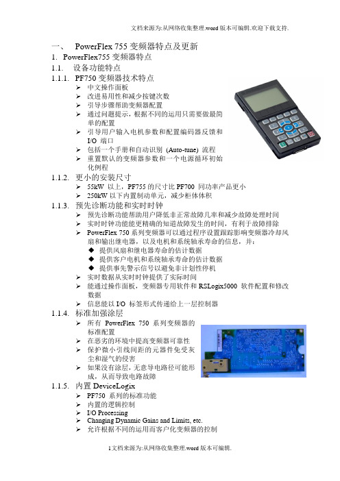
一、PowerFlex 755变频器特点及更新1.PowerFlex755变频器特点1.1.设备功能特点1.1.1.PF750变频器技术特点➢中文操作面板➢改进易用性和减少按键次数➢引导步骤帮助变频器配置➢通过问题提示,根据不同的运用只需要做最简单的配置➢引导用户输入电机参数和配置编码器反馈和I/O 端口➢包括一个手册和自动识别(Auto-tune) 流程➢重置默认的变频器参数和一个电源循环初始化例程1.1.2.更小的安装尺寸➢55kW 以上,PF755的尺寸比PF700 同功率产品更小➢250kW以下内置制动单元,减少柜体体积1.1.3.预先诊断功能和实时时钟➢预先诊断功能帮助用户降低非正常故障几率和减少故障处理时间➢实时时钟功能能更精确的知道故障发生的时间,有利于故障排除➢PowerFlex 750系列变频器可以通过程序设置跟踪影响变频器冷却风扇和输出继电器,以及电机和系统轴承寿命的信息,并:◆提供风扇和继电器寿命的估计数据◆提供客户电机和系统轴承寿命的估计数据◆提供事先警示信号以避免非计划性停机➢实时数据从实时时钟提供了实际时间➢能通过操作面板,变频器专用软件和RSLogix5000 软件配置和修改数据➢信息能以I/O 标签形式传递给上一层控制器1.1.4.标准加强涂层➢所有PowerFlex 750 系列变频器的标准配置➢在恶劣的环境中提高变频器可靠性➢保护微小引线间距的元器件免受灰尘和湿气的侵害➢如果没有涂层,无意导电路径可能形成,从而导致电路故障1.1.5.内置DeviceLogix➢PF750 系列的标准功能➢内置的逻辑控制➢I/O Processing➢Changing Dynamic Gains and Limits, etc.➢允许根据不同的运用而客户化变频器的控制➢单机控制➢更灵活,更广泛的控制➢变频器能自动响应当丢失上位机的通讯➢通过变频器软件工具进行编程◆DriveExplorer v6.02 (and higher)◆DriveTools SP v5.02 (and higher)◆RSLogix 5000 Drive AOPs v3.01(and higher)1.1.6.保护功能➢变频装置具有以下保护:过电流、过电压、欠电压、缺相、变频器过热、变频器过载、电机过载、外部报警输入、通用熔断器熔断保护、逆变器出错、输出短路保护、输出接地、瞬间停电保护等,而且所有参数、保护动作信号和故障信号要求可通过相应接口上传。
洛克威爾自動化 PowerFlex 750 系列交流變頻器 技術資料说明书
技術資料PowerFlex 750 系列交流變頻器原始說明主題頁次其他資源2產品概述2認證和規格6設計考量11保險絲及斷路器額定值36電纜考量事項59馬達考量事項61尺寸及重量64變頻器選項1152洛克威爾自動化出版品 750-TD001H-ZC-P - 2013 年 6 月PowerFlex 750 系列交流變頻器其他資源這些文件包含與洛克威爾自動化產品相關的其他資訊。
您可以至以下網址檢視或下載出版品:/literature/。
若要訂購書面的技術文件,請向本地 Allen-Bradley 自動化經銷商或洛克威爾銷售代表洽詢。
產品概述PowerFlex 750 系列是功能強大的交流變頻器系列,不僅易於使用,而且為眾多不同的工業應用系統提供絕佳彈性及效能。
PowerFlex 753 提供的一般用途控制器適用於功率最高達 350HP 及250kW 的應用系統。
PowerFlex 755 提供高達 2000HP 及 1500kW 的最大彈性及效能。
以下是 PowerFlex 750 系列具備的重要功能,善用這些功能所帶來的優勢可大幅提高產能。
•DeviceLogix ™ — 內嵌式控制器技術,支援離散輸出及變頻器控制功能之操作,變頻器更內建離散輸入和變頻器狀態資訊。
•預測診斷系統 — 讓變頻器隨時掌握影響冷卻風扇使用壽命及繼電器輸出的資訊。
此外,亦可編輯變頻器的程式,以監控機器或馬達軸承的運行時間。
•選項卡 — 每個變頻器都具備插槽式架構。
提供兩種產品共通的硬體控制選項,有助您降低庫存及零件的需求。
•安全扭力關斷及安全速度監控 — 可根據您的應用系統需求提供安全層級的選擇。
•通訊 — PowerFlex 755 附帶內建乙太網路連接埠。
可利用通訊模組輕鬆新增乙太網路至 PowerFlex 753。
•I/O — 適用額外類比和離散 I/O 之選項卡。
PowerFlex 753 附帶內建 I/O ,可透過選項卡輕鬆擴充。
Powerflex750变频器如何实现就地与DCS控制切换
Powerflex750变频器如何实现就地与DCS控制切换罗克韦尔Powerflex750变频器基本参数调试⼀览表参数号描述说明参数选择备注 P25 电机额定电压端⼝0: P25(电机额定电压)根据电机铭牌参数选择P26 电机额定电流端⼝0: P26(电机额定电流)根据电机铭牌参数选择P27 电机额定频率端⼝0: P27(电机额定频率)根据电机铭牌参数选择P28 电机额定转速端⼝0: P28(电机额定转速)根据电机铭牌参数选择P29 电机功率单位端⼝0: P29(电机功率单位)0=HP 1=KW P29=1P30 电机额定功率端⼝0: P30(电机额定功率)根据电机铭牌参数选择P31 电机极数端⼝0: P31(电动机极数)根据电机铭牌参数选择P35 电机控制模式端⼝0: P35(电机控制模式) 0=V/F;1=SV;2=感应电机节能;3=磁通⽮量P35=1 ⽆速度传感器⽮量控制P36 最⼤输出电压端⼝0: P36(最⼤输出电压) P36=380VP37 最⼤输出频率端⼝0: P37(最⼤输出频率) P37=50HzP300 速度单位端⼝0:P300(速度单位)0=(频率);1=(转速) P300=0P301 访问等级端⼝0: P301(访问等级)0=基本级 1=⾼级 2=专家级 P301=1P413 电机过载因⼦端⼝0: P413(电机过载因⼦);0~2P413=1.2 变频器的过载倍数P535 加速时间端⼝0: P535(加速时间)根据⼯艺及负载要求P537 减速时间端⼝0: P537(减速时间)根据⼯艺及负载要求变频器速度给定信号源的设定P545 速度基准值A选择端⼝0:P545(速度基准值A选择)=端⼝4:P50(模拟输⼊0)就地电位器给定频率信号P547 速度基准值A模拟值⾼限端⼝0: P547(速度基准值A模拟值⾼限)=50Hz P547=50HzP548 速度基准值A模拟值下限端⼝0: P548(速度基准值A模拟值低限)=00Hz P548=00HzP550 速度基准值B选择端⼝0:P550(速度基准值B选择)=端⼝4:P60(模拟输⼊1)远程DCS给定频率信号1参数号描述说明参数选择备注 P552 速度基准值B模拟值⾼限端⼝0: P552(速度基准值B模拟值⾼限)=50Hz P553 速度基准值B模拟值下限端⼝0: P553(速度基准值B模拟值低限)=00Hz变频器数字量输⼊的设定P308 ⽅向模式端⼝0: P308(⽅向模式)= 0 Unipolar(单极性) P308=0P150 数字输⼊配置端⼝0: P150=0 运⾏边缘 P150=0P163 DI数字量输⼊运⾏端⼝0: P163(数字输⼊运⾏)=禁⽤P164 DI数字量输⼊正向运⾏端⼝0: P164(数字输⼊正向运⾏)=端⼝4:P1的B00位=1 ;(数字输⼊DI0)当采⽤两线制起停控制模式时,由端⼝4上的DI0来控制变频器正向运⾏P165 DI数字量输⼊反向运⾏端⼝0: P165(数字输⼊反向运⾏)=端⼝4:P1的B05位=1 ;(数字输⼊DI5)当采⽤两线制起停控制模式时,由端⼝4上的DI5来控制变频器反向运⾏P173 DI转速选择0 端⼝0: P173 = 端⼝4:P1的B01位=1 (数字输⼊DI1)见附件图纸说明P174 DI转速选择1 端⼝0: P174 = 端⼝4:P1的B02位=1 (数字输⼊DI2)P175 DI转速选择2 端⼝0:P175=端⼝4:P1的B03位=1 (数字输⼊DI3)P324 逻辑屏蔽码端⼝0:将参数P324的Bit1-Bit6位设为0 P324(Bit0-Bit6)=0000001屏蔽端⼝1-6变频器数字量输出的设定P10 RO0继电器设置端⼝4: P10(RO0选择)=端⼝0:P935(变频器状态)的B07位=FaultP10=端⼝0:P935的B07位故障P20 RO1继电器设置端⼝4: P20(RO1选择)=端⼝0:P935(变频器状态)的B16位=RunningP20=端⼝0:P935的B16位运⾏变频器模拟量输⼊信号的设定P45 模拟量输⼊类型端⼝4: P45(模拟量输⼊0类型)的B00位=0电压信号输⼊;选择AI0为电压信号输⼊通过I/O卡端⼦排上端跳线来设置端⼝4: P45(模拟量输⼊1类型)的B01位=1为电流信号输⼊选择AI1为电流信号输⼊2参数号描述说明参数选择备注P50 模拟输⼊0值端⼝4:显⽰模拟量输⼊0的输⼊信号值 ROP51 模拟输⼊0上限端⼝4: P51(模拟量输⼊0上限)=10.0V P51=10V0~10V可调节P52 模拟输⼊0下限端⼝4: 52(模拟量输⼊0下限)=0V P52=0VP60 模拟输⼊1值端⼝4:显⽰模拟量输⼊1的输⼊信号值 ROP61 模拟输⼊1上限端⼝4: P61(模拟量输⼊1上限)=20.0mA P61=20mA0~20mA可调节P62 模拟输⼊1下限端⼝4: 62(模拟量输⼊1下限)=4mA P62=4mA变频器模拟量输出信号的设定P70 模拟量输出类型端⼝4: P70(模拟量输出0类型)的B00位=1电流信号输出;P70的B00位=1(电流信号输出)端⼝4:P70(模拟量输出1类型)的B01位=1电流信号输出;P70的B01位=1(电流信号输出)P75 模拟输出0选择端⼝4: P75(模拟量输出0选择)=端⼝0:P1P1=变频器输出频率P80 模拟输出0上限端⼝4: P80(模拟量输出0上限)=20.0mA P80=20mA0~20mA可调节P81 模拟输出0下限端⼝4: P81(模拟量输出0下限)=4mA P81=4mAP82 模拟输出0值端⼝4:显⽰模拟量输出0输出信号值 ROP85 模拟输出1选择端⼝4: P85(模拟量输出0选择)=端⼝0:P7P7=变频器输出电流P90 模拟输出1上限端⼝4: P90(模拟量输出0上限)=20.0mA P90=20mA0~20mA可调节P91 模拟输出1下限端⼝4: P91(模拟量输出0下限)=4mA P91=4mAP92 模拟输出1值端⼝4:显⽰模拟量输出1输出信号值 RO3上电调试前先检查I/O卡上的Ai信号模式是否与实际使⽤接线相符合,如果与实际使⽤不相符合,参照下图进⾏跳接。
PF750系列变频器快速调试手册

PF750系列变频器快速调试手册产品支持部龚波 gbo@ 2013-12-31PowerFlex 753系列变频器主板结构概述:由于PF753变频器本体自带有部分IO点,其AI输入的输入类型跳线需要选择:J4在3、4位置代表输入为电压模式,J4在1、2位置代表输入为电流模式,参考参数PORT 0:Parameter 255 Anlg In Type。
当PF753本体的IO点数不够时也可以加配IO选项卡(第7页)PowerFlex 755系列变频器主板结构概述:由于PF755变频器本体无IO点,只有加配IO卡,其IO卡的AI输入的输入类型跳线需要选择:跳线在下面的位置代表输入为电压模式,跳线在上面位置代表输入为电流模式,参考参数PORT X(IO卡插的槽号):Parameter 45 Anlg In Type。
以下是一些变频器IO接线的实例:推荐 10k 欧电位计(2k 欧最小),电位计接法 外部电压信号或者电流信号输入调速接线方法模拟量输出接法两线制启动变频器的内部电源及外部电源接法示例三线制启动变频器的内部电源及外部电源接法电机PTC接法,参数参照 “参数部分之5模拟量配置及继电器输出功能配置”参数部分:1、电机控制部分注:以上参数需要按照现场电机实际情况来填写。
其中35#建议选择成1或者3,转矩不足时选择1,电流相对难以控制的情况下选择3,这两种控制方式必须要对电机进行自整定(70#参数)。
2、变频器配置参数变频器的配置参数,301#尽量选择2,这样能访问的参数会更多。
速度值可以改变成正负值来控制方向,比如+10Hz或者-10Hz代表的就是两个方向是速度。
370#一般在离心风机和离心泵、普通搅拌时选择惯性停车。
3、DI功能配置参数以上是数字量输入一些功能参数,其中150#参数,选0表示DI信号是上升沿检测,选1是表示正常的常开常闭检测,当控制方式为三线制时选择0,控制方式为二线制时选择1。
152#~172#参数,使用方式是将相应的功能参数指向相应的DI点,例如:Port X:1 Dig In Sts :Input Y,其中X表示槽号,0表示变频器,IO卡会在5~8号槽,Y表示DI的点数号。
PowerFlex 750-Series 网络通信选项模块安装指南说明书
Installation InstructionsOriginal InstructionsNetwork Communication Option ModuleCatalog Numbers 20-750-BNETIP, 20-750-DNET, 20-750-PBUS, 20-750-PNET, 20-750-PNET2P, 20-750-CNETC, 20-750-ENETR, 20-750-ENET2PProduct AdvisoriesTopic Page Product Advisories 1Install the Network Communication Option Module 2ATTENTION: Risk of injury or death exists. PowerFlex® 750-Series drives may contain high voltages that can cause injury or death. Remove power from the drive, and then verify power has been discharged before removing the drive cover.ATTENTION: Risk of equipment damage exists. The network communication option module contains electrostatic discharge (ESD) sensitive parts that can be damaged if you do not follow ESD control procedures. Static control precautions are required when handling the card. If you are unfamiliar with static control procedures, see Guarding Against Electrostatic Damage, publication 8000-4.5.2.IMPORTANT These instructions describe installing the network communication module into the drive. Depending on the type of network communication option module you are installing, additional, important procedures may also need to be performed. See the appropriate user manuals for detailed information about these procedures.Network Communication Option Module Installation InstructionsInstall the Network Communication Option Module1.Remove power from the drive.2.Remove the drive cover and lift up the drive HIM cradle (with or without the HIM installed) to its open position toaccess the drive control pod.3.into the connector.2Rockwell Automation Publication 750COM-IN003A-EN-P - January 2023Rockwell Automation Publication 750COM-IN003A-EN-P - January 20233Network Communication Option Module Installation Instructions4.Remove the lower T15 Torx mounting screw (Detail A) from the network communication module that is to the left of the PROFIBUS or PROFINET network communication module. To remove the captive T15 Torx screw, the module must be removed to back the screw out of the mounting clip.5.Replace the larger T15 Torx screw with the smaller spare T8 Torx mounting screw that was shipped with the PROFIBUS or PROFINET network communication module.6.Tighten both of the option module mounting screws to the pod mounting bracket to properly ground the module to the drive. Tighten both screws to the recommended torque shown in the following figure.IMPORTANT If you are using a PROFIBUS or PROFINET network communication module (20-750-PBUS, 20-750-PNET, or 20-750-PNET2P) with another network communication module that is positioned in the port to the left of the PROFIBUS or PROFINET module, you must replace the T15 Torx screw that holds the other network communication module to the lower mounting bracket.Replace the T15 Torx screw with a spare T8 Torx screw that is included with PROFIBUS and PROFINET modules. Due to its larger size, it is possible for the T15 Torx screw to come into contact with the PROFIBUS / PROFINET cable connector and cause faulty operation. Using the smaller T8 Torx screw helps eliminate this problem.Perform step 4 and step 5 if another network communication module is positioned in the port to the left of the PROFIBUS or PROFINET network communication module; otherwise, disregard these steps and go to step 6.Detail APublication 750COM-IN003A-EN-P - January 2023Copyright © 2023 Rockwell Automation, Inc. All rights reserved. Rockwell Otomasyon Ticaret A.Ş. Kar Plaza İş Merkezi E Blok Kat:6 34752, İçerenköy, İstanbul, Tel: +90 (216) 5698400 EEE Yönetmeli ğine UygundurAllen-Bradley, expanding human possibility, PowerFlex, and Rockwell Automation are trademarks of Rockwell Automation,Inc.Trademarks not belonging to Rockwell Automation are property of their respective companies.Your comments help us serve your documentation needs better. If you have any suggestions on how to improve our content, complete the form at rok.auto/docfeedback .For technical support, visit rok.auto/support.Waste Electrical and Electronic Equipment (WEEE)Rockwell Automation maintains current product environmental compliance information on its website at rok.auto/pec.At the end of life, this equipment should be collected separately from any unsorted municipal waste.Additional ResourcesThese documents contain additional information concerning related products from Rockwell Automation.You can view or download publications at rok.auto/literature .ResourceDescription PowerFlex 20-750-BNETIP BACnet/IP Option Module User Manual, publication 750COM-UM005Provides information about using the PowerFlex 20-750-BNETIP BACnet/IP Option ModulePowerFlex 20-750-CNETC Coaxial ControlNet Option Module User Manual, publication 750COM-UM003Provides information about using the PowerFlex Coaxial ControlNet Option Module PowerFlex 20-750-DNET DeviceNet Option Module User Manual, publication 750COM-UM002Provides information about using the PowerFlex DeviceNet Option Module PowerFlex 20-750-ENETR/ENET2P Dual-port EtherNet/IP Option Module, publication 750COM-UM008Provides information about using the PowerFlex 20-750-ENETR/ENET2P Dual-port EtherNet/IP Option Module PowerFlex 20-750-PBUS Profibus DPV1 Option Module User Manual, publication 750COM-UM004Provides information about using the PowerFlex Profibus DPV1 Option Module PowerFlex PROFINET Single- and Dual-port Option Modules User Manual, publication 750COM-UM007BProvides information about using the PowerFlex PROFINET Single- and Dual-port Option Modules Industrial Automation Wiring and Grounding Guidelines, publication 1770-4.1Provides general guidelines for installing a Rockwell Automation industrial system.Product Certifications website, rok.auto/certifications .Provides declarations of conformity, certificates, and other certification details.。
罗伯尔自动化产品750-系列EMC板和核心说明书
Installation InstructionsOriginal InstructionsPowerFlex 750-Series EMC Plate and Cores - Frames 1 (7)Catalog Numbers 20F and 20G Frames 1...5 (200…240/400…480V AC)Frames 3…5 (600V AC) Frame 6 and Frame 7 (600/690V AC)Summary of ChangesThis publication contains new and updated information as indicated in the following table.2Rockwell Automation Publication 750-IN006H-MU-P - June 2017PowerFlex 750-Series EMC Plate and Cores - Frames 1 (7)20-750-EMC1-F1Frame 1200…240/400…480V AC 20-750-EMC1-F2,F3Frames 2 and Frame 3200…240/400…480V AC20-750-EMC1-F4,F5(1)Frames 4 and Frame 5200…240/400…480V AC(1)Frames 6 and Frame 7, 200…240/400…480V AC drives do not require EMC cores or plates to meet EMC requirements.20-750-EMC3-F3Frame 3600V AC 20-750-EMC3-F4, F5Frames 4 and Frame 5600V AC20-750-EMC3-F6, F7Frames 6 and Frame 7 (IP20 after installation)600/690V AC 20-750-EMC5-F6, F7Frames 6 and Frame 7600/690V ACIMPORTANTGrounding and power jumper configuration must be appropriate for EMC applications. See Drive Power Jumper Configuration in the PowerFlex ® 750-Series AC Drives Installation Instructions, publication 750-IN001for details.1L1L2L32Frame 6 ShownRockwell Automation Publication 750-IN006H-MU-P - June 20173PowerFlex 750-Series EMC Plate and Cores - Frames 1 (7)200...240/400...480V AC Input Drives – Frames 1 (5)4600/690V – see page 64Rockwell Automation Publication 750-IN006H-MU-P - June 2017PowerFlex 750-Series EMC Plate and Cores - Frames 1 (7)Rockwell Automation Publication 750-IN006H-MU-P - June 20175600/690V AC Input Drives – Frames 3 (7)6Rockwell Automation Publication 750-IN006H-MU-P - June 2017PowerFlex 750-Series EMC Plate and Cores - Frames 1 (7)Rockwell Automation Publication 750-IN006H-MU-P - June 20177PowerFlex 750-Series EMC Plate and Cores - Frames 1 (7)8Rockwell Automation Publication 750-IN006H-MU-P - June 2017PowerFlex 750-Series EMC Plate and Cores - Frames 1 (7)Rockwell Automation Publication 750-IN006H-MU-P - June 20179PowerFlex 750-Series EMC Plate and Cores - Frames 1 (7)10Rockwell Automation Publication 750-IN006H-MU-P - June 2017PowerFlex 750-Series EMC Plate and Cores - Frames 1 (7)Notes:Rockwell Automation Publication 750-IN006H-MU-P - June 201711Allen-Bradley, PowerFlex, Rockwell Automation, and Rockwell Software are trademarks of Rockwell Automation, Inc.Trademarks not belonging to Rockwell Automation are property of their respective companies.Rockwell Otomasyon Ticaret A.Ş., Kar Plaza İş Merkezi E Blok Kat:6 34752 İçerenköy, İstanbul, T el: +90 (216) 5698400Rockwell Automation maintains current product environmental information on its website at /rockwellautomation/about-us/sustainability-ethics/product-environmental-compliance.page.Publication 750-IN006H-MU-P - June 2017Supersedes Publication 750-IN006G-MU-P-February 2014Copyright © 2017 Rockwell Automation, Inc. All rights reserved. Printed in the U.S.A.。
PowerFlex 750系列可調頻交流變頻器安裝說明说明书
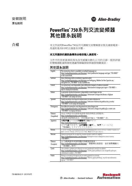
安裝說明750-IN001M-ZC-P - 2013年8月原始說明PowerFlex ® 750系列交流變頻器 其他語系說明介紹本文件說明PowerFlex 750系列可調頻交流變頻器安裝及連接電源、 馬達和基本I/O 的五個基本步驟。
本文所提供的資訊係專供合格安裝人員使用。
文件中的其他資源段落為洛克威爾自動化公司的目錄,提供詳細的變頻器配線與接地建議等障礙排除與維修相關資訊。
其他語系說明English This instruction sheet is available in multiple languages at/literature. Select publication language and type “750-IN001“ in the search field.German Diese Anleitung steht in mehreren Sprachen unter/literature zur Verfügung. Wählen Sie Ihre Sprache aus, und geben Sie …750-IN001“ in das Suchfeld ein.French Ces instructions sont disponibles dans différentes langues à l’adresse suivante:/literature. Sélectionner la langue puis taper « 750-IN001 » dans le champ de recherche.Italian La presente scheda d’istruzione è disponibile in varie lingue sul sito/literature. Selezionare la lingua desiderata e digitare “750-IN001“ nel campo di ricerca.Spanish Puede encontrar esta hoja de instrucciones en varios idiomas en/literature. Selecione el idioma de publicación y escriba “750-IN001“ en el campo de búsqueda.Portuguese Esta folha de instruções está disponível em várias línguas em/literature. Seleccione a língua de publicação e entre com “750-IN001“ no espaço de busca.Chinese (Simplified)从以下网页可以获得本说明书的多种语言的版本: /literature 。
PF750系列变频器快速调试手册

PF750系列变频器快速调试手册产品支持部龚波 gbo@ 2013-12-31PowerFlex 753系列变频器主板结构概述:由于PF753变频器本体自带有部分IO点,其AI输入的输入类型跳线需要选择:J4在3、4位置代表输入为电压模式,J4在1、2位置代表输入为电流模式,参考参数PORT 0:Parameter 255 Anlg In Type。
当PF753本体的IO点数不够时也可以加配IO选项卡(第7页)PowerFlex 755系列变频器主板结构概述:由于PF755变频器本体无IO点,只有加配IO卡,其IO卡的AI输入的输入类型跳线需要选择:跳线在下面的位置代表输入为电压模式,跳线在上面位置代表输入为电流模式,参考参数PORT X(IO卡插的槽号):Parameter 45 Anlg In Type。
以下是一些变频器IO接线的实例:推荐 10k 欧电位计(2k 欧最小),电位计接法 外部电压信号或者电流信号输入调速接线方法模拟量输出接法两线制启动变频器的内部电源及外部电源接法示例三线制启动变频器的内部电源及外部电源接法电机PTC接法,参数参照 “参数部分之5模拟量配置及继电器输出功能配置”参数部分:1、电机控制部分注:以上参数需要按照现场电机实际情况来填写。
其中35#建议选择成1或者3,转矩不足时选择1,电流相对难以控制的情况下选择3,这两种控制方式必须要对电机进行自整定(70#参数)。
2、变频器配置参数变频器的配置参数,301#尽量选择2,这样能访问的参数会更多。
速度值可以改变成正负值来控制方向,比如+10Hz或者-10Hz代表的就是两个方向是速度。
370#一般在离心风机和离心泵、普通搅拌时选择惯性停车。
3、DI功能配置参数以上是数字量输入一些功能参数,其中150#参数,选0表示DI信号是上升沿检测,选1是表示正常的常开常闭检测,当控制方式为三线制时选择0,控制方式为二线制时选择1。
152#~172#参数,使用方式是将相应的功能参数指向相应的DI点,例如:Port X:1 Dig In Sts :Input Y,其中X表示槽号,0表示变频器,IO卡会在5~8号槽,Y表示DI的点数号。
750数据手册
( 固态控件的应用、安装和维护的安全指南 )
在线获取网址 … /literature
产品概况
PowerFlex 750 系列交流变频器功能强大,具有易于使用、灵活且 适用于各种工业应用的特点。 PowerFlex 753 可为功率达 250 kW 的应用提供多种用途的控制。 PowerFlex 755 可提供最大的灵活 性,并适用于功率达 450 kW 的应用。
技术数据
PowerFlex 750 系列交流变频器
PowerFlex 750 系列交流变频器技术数据
目录
产品概况 . . . . . . . . . . . . . . . . . . . . . . . . . . . . . . . . . . . . . . . . . . . . . . . . . . . . . . . . . . 3 产品目录号说明 . . . . . . . . . . . . . . . . . . . . . . . . . . . . . . . . . . . . . . . . . . . . . . . . . 4 PowerFlex 750 系列变频器 . . . . . . . . . . . . . . . . . . . . . . . . . . . . . . . . . . . . . . . . . 5 认证 . . . . . . . . . . . . . . . . . . . . . . . . . . . . . . . . . . . . . . . . . . . . . . . . . . . . . . . . . . . . 6 环境技术规格 . . . . . . . . . . . . . . . . . . . . . . . . . . . . . . . . . . . . . . . . . . . . . . . . . . . 6 技术规范. . . . . . . . . . . . . . . . . . . . . . . . . . . . . . . . . . . . . . . . . . . . . . . . . . . . . . . . 8
PowerFlex750快速启动说明
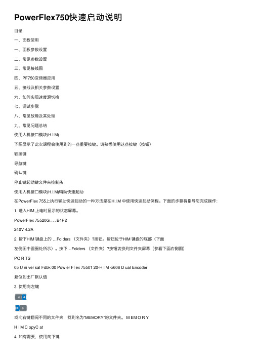
PowerFlex750快速启动说明⽬录⼀、⾯板使⽤⼀、⾯板参数设置⼆、常见参数设置三、常见接线图四、PF750变频器应⽤五、接线及相关参数设置六、如何实现速度源切换七、调试步骤⼋、常见故障及其处理九、常见问题总结使⽤⼈机接⼝模块(H.I.M)下图显⽰了此次课程会使⽤到的⼀些重要按键。
请熟悉使⽤这些按键(按钮)软按键导航键确认键停⽌键起动键⽂件夹控制条使⽤⼈机接⼝模块(H.I.M)辅助快速起动在PowerFlex 755上执⾏辅助快速起动的⼀种⽅法是在H.I.M 中使⽤快速起动例程。
下⾯的步骤将指导您完成操作:1. 进⼊HIM 上电时显⽰的状态屏幕。
PowerFlex 75520G . . . B4P2240V 4.2A2. 按下HIM 键盘上的 …Folders (⽂件夹)?按钮。
按钮位于HIM 键盘的底部(下⾯左侧图中圆圈处所⽰)。
按下…Folders (⽂件夹)?按钮切换到⽂件夹屏幕(参看下⾯右侧图)PO R TS05 U ni ver sal Fdbk 00 Pow er Fl ex 75501 20-H I M -x606 D ual Encoder复位到出⼚默认值3. 使⽤向左键或向右键翻阅不同的⽂件夹,找到名为“MEMORY”的⽂件夹。
M EM O R YH I M C opyC at4. 如有需要,使⽤向下键选中… Set Defaults (设置默认值)? ,并按下位于HIM 键盘中间位置的Enter(确认)键,确定选择。
5. 完成上⾯的步骤后,出现如下画⾯。
使⽤向下键选中…This Port only (仅此端⼝)?。
按下位于HIM 键盘的中间位置的Enter(确认)键,确定选择。
ESC INFOPor t 00Set D ef aul t s H ost and Por t s ( Pr ef er r ed)Thi s Por t O nl y6.使⽤标有…ALL?的软按键,将变频器中的全部参数复位为默认值。
PowerFlex 750 系列交流变频器原始说明201306
技术数据PowerFlex 750 系列交流变频器原始说明主题页码其它资源2产品概况2认证和技术规范6设计考虑因素11熔断器和断路器额定值36电缆考虑事项59电机考虑因素61尺寸和重量64变频器选件1152罗克韦尔自动化出版物 750-TD001H-ZH-P - 2013 年 6 月PowerFlex 750 系列交流变频器其它资源以下文档包含与罗克韦尔自动化产品有关的其它信息。
可以在 /literature/ 上查看或下载出版物。
如需订购技术文档的纸印本,请联系当地的 Allen-Bradley 分销商或罗克韦尔自动化销售代表。
产品概况PowerFlex 750 系列交流变频器坚固耐用,其易用性、灵活性和极佳的性能适用于各种工业应用。
PowerFlex 753 可为功率高达350 Hp 和 250 kW 的应用提供常规控制。
PowerFlex 755 的灵活性最高,性能范围高达 2000 Hp 和 1500 kW 。
PowerFlex 750 系列具有如下一系列核心特性,可帮助用户最大程度提高生产力:•DeviceLogix ™ — 嵌入式控制技术,支持离散量输出处理和变频器控制功能,同时使用离散量输入和变频器板载的变频器状态信息。
•预测性诊断 — 允许变频器记录能影响其冷却风扇寿命和继电器输出的信息。
也可以对变频器进行编程,使其监控机器或电机轴承的运行时间。
•选项卡 — 每个变频器都具有一个插槽架构。
这两款产品支持相同的硬件控制选件,有助于降低库存和备件要求。
•安全断开扭矩和安全速度监控 — 让您可以根据应用需求选择合适的安全等级。
•通信 — PowerFlex 755 内置以太网端口。
可以使用通信模块轻松地为 PowerFlex 753 添加以太网功能。
标题出版物PowerFlex 750-Series Drive Installation Instructions(PowerFlex 750 系列变频器安装说明)750-IN001PowerFlex 750-Series Programming Manual (PowerFlex 750 系列变频器编程手册)750-PM001Enhanced PowerFlex 7-Class Human Interface Module (HIM) User Manual (增强型 PowerFlex 7系列人机界面模块 (HIM) 用户手册)20HIM-UM001PowerFlex 750-Series Safe Torque Off User Manual (PowerFlex 750 系列安全断开扭矩用户手册)750-UM002Safe Speed Monitor Option Module for PowerFlex 750-Series AC Drives Reference Manual (PowerFlex 750 系列交流变频器的安全速度监控选件模块参考手册)750-RM001PowerFlex 7-Class Network Communication Adapter User Manuals (PowerFlex 7 系列网络通信适配器用户手册)750COM-UMDynamic Braking Resistor Calculator (动态制动电阻计算器)PFLEX-AT001Wiring and Grounding Guidelines for PWM AC Drives (PWM 交流变频器的接线和接地指南)DRIVES-IN001Preventive Maintenance of Industrial Control and Drive System Equipment (工业控制和变频器系统设备的预防性维护)DRIVES-TD001Safety Guidelines for the Application, Installation and Maintenance of Solid State Control (固态控制设备的应用、安装与维护安全指南)SGI-1.1罗克韦尔自动化出版物 750-TD001H-ZH-P - 2013 年 6 月3PowerFlex 750 系列交流变频器•I/O — 选项卡可用于附加的模拟量和离散量 I/O 。
- 1、下载文档前请自行甄别文档内容的完整性,平台不提供额外的编辑、内容补充、找答案等附加服务。
- 2、"仅部分预览"的文档,不可在线预览部分如存在完整性等问题,可反馈申请退款(可完整预览的文档不适用该条件!)。
- 3、如文档侵犯您的权益,请联系客服反馈,我们会尽快为您处理(人工客服工作时间:9:00-18:30)。
给变频器上电 . . . . . . . . . . . . . . . . . . . . . . . . . . . . . . . . . . . . . . . . . . . . . . . . . . 12 变频器设置. . . . . . . . . . . . . . . . . . . . . . . . . . . . . . . . . . . . . . . . . . . . . . . . . . . . . 13
对于因使用本手册中所述信息、电路、设备或软件而引起的专利问题,罗克韦尔自动化不承担任何责任。
未经罗克韦尔自动化公司书面许可,任何单位或个人不得复制本手册之全部或部分内容。
在整本手册中,我们在必要的地方使用了以下注释,来提醒您注意相关的安全事宜。
警告:标识在危险环境下可能导致爆炸,进而造成人员伤亡、财产损坏或经济损失的 行为或情况的信息。
步骤 1:收集所需的信息
记录电机铭牌数据 . . . . . . . . . . . . . . . . . . . . . . . . . . . . . . . . . . . . . . . . . . . . . . 7
步骤 2:验证变频器安装
识别您的变频器类型 . . . . . . . . . . . . . . . . . . . . . . . . . . . . . . . . . . . . . . . . . . . . 8 查验电源线. . . . . . . . . . . . . . . . . . . . . . . . . . . . . . . . . . . . . . . . . . . . . . . . . . . . . . 8 查验电源跳线配置 . . . . . . . . . . . . . . . . . . . . . . . . . . . . . . . . . . . . . . . . . . . . . . 9 查验 I/O 接线 . . . . . . . . . . . . . . . . . . . . . . . . . . . . . . . . . . . . . . . . . . . . . . . . . . . 9 信号源连接位置. . . . . . . . . . . . . . . . . . . . . . . . . . . . . . . . . . . . . . . . . . . . . . . . 10
注意:标识可能会导致人员伤亡、财产损坏或经济损失的行为或情况的信息。“ 注意 ” 可以帮助您识别危险、避免危险并了解后果。
重要事项 标识对成功应用和理解产品有重要作用的信息。
标签可能位于设备上或设备内,用于提供特定警示。
触电危险:位于设备 ( 例如,变频器或电机 ) 表面或内部的标签,提醒人们可能存在 危险电压。
罗克韦尔自动化出版物 750-QS001A-ZH-P - 2015 年 3 月
3
目录
继电器输出接线. . . . . . . . . . . . . . . . . . . . . . . . . . . . . . . . . . . . . . . . . . . . . . . . 76 禁用 HIM 启动功能 . . . . . . . . . . . . . . . . . . . . . . . . . . . . . . . . . . . . . . . . . . . . 77 HIM 拷贝功能. . . . . . . . . . . . . . . . . . . . . . . . . . . . . . . . . . . . . . . . . . . . . . . . . . 78 电机过载 . . . . . . . . . . . . . . . . . . . . . . . . . . . . . . . . . . . . . . . . . . . . . . . . . . . . . . . 82 如需联系技术支持 . . . . . . . . . . . . . . . . . . . . . . . . . . . . . . . . . . . . . . . . . . . . . 83
步骤 4:设置速度基准值和启动 / 停止
输入 / 输出配置检查表. . . . . . . . . . . . . . . . . . . . . . . . . . . . . . . . . . . . . . . . . 17
步骤 5:特别注意事项
步骤 6:查验变频器的运行情况
配置考虑事项 . . . . . . . . . . . . . . . . . . . . . . . . . . . . . . . . . . . . . . . . . . . . . . . . . . 19
Allen-Bradley, Rockwell Software, and Rockwell Automation are trademarks of Rockwell Automation, Inc. 不属于罗克韦尔自动化的商标是其各自所属公司的财产。
目录
重要用户须知 . . . . . . . . . . . . . . . . . . . . . . . . . . . . . . . . . . . . . . . . . . . . . . . . . . . 2
快速入门
PowerFlex 750 系列交流变频器
重要用户须知
在安装、配置、操作或维护本产品前,请仔细阅读本文档以及其它资源部分列出的文档,以了解有关 此设备的安装、配置和操作信息。用户需要熟悉安装和接线说明以及所有适用规范、法律和标准的相关 要求。
安装、调节、投入运行、使用、装配、拆卸和维护等活动都需要由经过适当培训的人员遵照适用的操作 规范来执行。
烧伤危险:位于设备 ( 例如,变频器或电机 ) 表面或内部的标签,提醒人们表面可能 存在高温危险。
弧闪危险:标签可能位于设备上或设备内 (例如电机控制中心),用于提醒人们 可能存在弧闪。弧闪将造成严重的人身伤害或死亡。穿戴适当的个人防护设备 (PPE)。 遵守安全工作规范和个人防护设备 (PPE) 的所有法规要求。
参考部分
确定变频器类型. . . . . . . . . . . . . . . . . . . . . . . . . . . . . . . . . . . . . . . . . . . . . . . . 22 电源接线 . . . . . . . . . . . . . . . . . . . . . . . . . . . . . . . . . . . . . . . . . . . . . . . . . . . . . . . 23 电源跳线 . . . . . . . . . . . . . . . . . . . . . . . . . . . . . . . . . . . . . . . . . . . . . . . . . . . . . . . 27 识别选件模块和兼容端口 . . . . . . . . . . . . . . . . . . . . . . . . . . . . . . . . . . . . . . 31 变频器设备端口. . . . . . . . . . . . . . . . . . . . . . . . . . . . . . . . . . . . . . . . . . . . . . . . 33 HIM 概述. . . . . . . . . . . . . . . . . . . . . . . . . . . . . . . . . . . . . . . . . . . . . . . . . . . . . . . 34 恢复出厂默认设置 . . . . . . . . . . . . . . . . . . . . . . . . . . . . . . . . . . . . . . . . . . . . . 37 典型的速度基准值示例 . . . . . . . . . . . . . . . . . . . . . . . . . . . . . . . . . . . . . . . . 38 EtherNet/IP 通信 . . . . . . . . . . . . . . . . . . . . . . . . . . . . . . . . . . . . . . . . . . . . . . . 52 2 线制和 3 线制控制 . . . . . . . . . . . . . . . . . . . . . . . . . . . . . . . . . . . . . . . . . . . . 63 变频器状态指示灯 . . . . . . . . . . . . . . . . . . . . . . . . . . . . . . . . . . . . . . . . . . . . . 65 动态制动电阻 . . . . . . . . . . . . . . . . . . . . . . . . . . . . . . . . . . . . . . . . . . . . . . . . . . 66 加速和减速时间. . . . . . . . . . . . . . . . . . . . . . . . . . . . . . . . . . . . . . . . . . . . . . . . 68 方向模式 . . . . . . . . . . . . . . . . . . . . . . . . . . . . . . . . . . . . . . . . . . . . . . . . . . . . . . . 70 模拟量输出接线. . . . . . . . . . . . . . . . . . . . . . . . . . . . . . . . . . . . . . . . . . . . . . . . 74 数字量输出接线. . . . . . . . . . . . . . . . . . . . . . . . . . . . . . . . . . . . . . . . . . . . . . . . 75
