DIN2093德标碟形弹簧垫圈-2006中文版
碟形弹簧设计手册

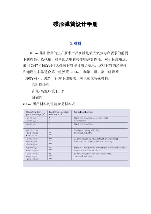
碟形弹簧设计手册1.材料Mubea碟形弹簧的生产要求产品在满足最大疲劳寿命要求的前提下获得最小松弛量。
材料的选取直接影响弹簧性能。
对于标准用途,采用Ck67和50CrV4作为弹簧材料即可满足要求。
这些材料的经济性和通用性非常适合第一组弹簧(Ck67)和第二组、第三组弹簧(50CrV4)。
此外,针对下述要求,可以选取特殊材料。
|高耐腐蚀性|在低/高温环境下工作|耐磁性Mubea所用材料的性能参见材料表。
2.材料与防腐蚀2.1标准材料Ck67(DIN1.1231)Ck67是碟形弹簧低应力应用情况下的经济型钢种,按DIN2093标准规定,该材料只适用于第一组弹簧(厚度<1.25mm)。
特殊情况下,也可用于厚度小于4mm的弹簧。
50CrV4(DIN1.8159)50CrV4是碟形弹簧最常用的材料。
由于其高合金成分,在-15℃至+150℃温度范围时,可使弹簧具有最佳性能。
如可降低弹簧耐久性,该材料最低应帮温度可达成-25℃,如采用热强压处理,其最高应用温度+200℃。
该材料抗松驰性能优于非合金钢。
51CrMoV4(DIN1.7701)51CrMoV4(DIN1.7701)性能与50CrV41(8159)相似。
由于加入了钼合金元素,材料厚度在40mm以下的工件均具有良好的淬透性。
由于其韧性优于50CrV4。
因此该材料更适用于0℃至-20℃温度范围。
2.2耐磨性材料由于较高的镍合金含量,耐腐性材料在初始状态下具有奥氏体晶格,因此不能象常规材料那样采用奥氏体或马氏体等温淬火。
而腐蚀弹簧钢通过混合晶体变形、冷轧加工硬化(见DIN17224)和沉淀硬化(х7CrNiAl177)来获得强度。
一定程度的冷扎加工硬化可使碟型弹簧获得足够的强度。
因此,对该种材料的最大厚度有严格的限制。
耐腐蚀材料碟型弹簧可以在极低温度下使用,但其通过冷轧过程获得的强度会在温度高于+200℃时消失。
х12CrNi177(DIN1.4310)DIN17224标准的镍铬金х12CrNi177通常用于耐腐的碟型弹簧。
中外紧固件对照表
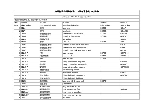
德国标准和国际标准、中国标准中英文对照表发布日期:2007-03-14 浏览次数:829德国标准和国际标准、中国标准中英文对照表序号德国标准中文品名英文品名国际标准中国标准Item DIN-Standard Description in Chinese Description in English ISO-Standard GB-Standard 1DIN1圆锥销taper pins ISO2339GB117 2DIN7圆柱销parallel pins ISO2338GB119-86 3DIN84开槽圆柱头螺钉slotted cheese head screws ISO1207GB65-85 4DIN85开槽盘头螺钉slotted pan head screws ISO1580GB67-85 5DIN93单耳止动垫圈tab washers GB854 6DIN94开口销split cotter pins ISO1234GB91 7DIN95开槽半沉头木螺钉slotted raised csk head wood screws GB101 8DIN96开槽半圆头木螺钉slotted round head wood screws GB99 9DIN97开槽沉头木螺钉slotted countersunk head wood screws GB100 10DIN125-A平垫plain washers ISO7089GB97.1-85 11DIN125-B平垫(带倒角)mediun washers ISO7090GB97.2-85 12DIN126平垫plain washers ISO709113DIN127-A重型弹垫spring lock washers,tang ends GB7244 14DIN127-B标准弹垫spring lock washers,square ends GB93-87 15DIN128-A鞍形弹垫single coil spring lock washers GB7245-87 16DIN137-A弹簧止动垫圈curved spring washers17DIN137-B波形弹垫wave spring washers GB955 18DIN186T型方颈螺栓T-head bolts with square neck GB37-88 19DIN188T型双接头螺栓T-head bolts with double nip20DIN258螺纹圆锥销taper pins with threaded end ISO873721DIN261T型头螺栓T-head bolts22DIN315AF蝶型螺母(美制)wing nuts amercia form23DIN315DF蝶型螺母(德制)wing nuts germany form GB62-88 24DIN316AF蝶型螺钉(美制)wing screws amercia form25DIN317DF蝶型螺钉(德制)wing screws germany form26DIN319圆球型盖型螺母ball knobs27DIN404开槽带孔球面圆柱头螺钉slotted capstan screws GB832-88 28DIN417开槽长圆柱端紧定螺钉slotted set srews with full dog point ISO7435GB75-85 29DIN427开槽平端紧定螺钉(半牙)slotted set srews with chamfered end ISO2342GB73-85 30DIN431小六角特薄细牙螺母pipe nuts with thread GB808-88 31DIN432外舌止动垫圈external tap GB856-88 32DIN433小垫圈(用于圆柱头螺钉)washers for cheese head screws ISO7092GB848-95 33DIN434方斜垫圈(U型)square taper washers for U-section GB852-88 34DIN435方斜垫圈(I型)square taper washers for I-sections GB852-88 35DIN436方垫圈square washers36DIN438开槽凹端紧定螺钉slotted set with cup point ISO7436GB74-85 37DIN439六角薄螺母hexagon thin nuts ISO4035GB6172-86 38DIN439细牙六角薄螺母hexagon thin nuts ISO8675GB6173-86 39DIN440木螺钉专用垫圈rounds washers for wood constructions ISO709440DIN443密封帽sealing caps,push-in type41DIN444活节螺栓B 型eye bolts form B GB798-88 42DIN462内舌止动垫圈internal tab washers43DIN463双耳止动垫圈washers with two taps GB855-88 44DIN464滚花高头螺钉knurled thumb screws with collar GB834-88 45DIN465开槽滚花高头螺钉slotted knurled thumb screws with collar46DIN466滚花高螺母knurled thumb nuts with collar GB806-88 47DIN467滚花薄螺母knurled thumb thin nuts GB807-88 48DIN470锁紧垫圈sealing washers49DIN471轴用弹性挡圈retaining rings for shafts(external),circlips GB894.1-86 50DIN472孔用弹性挡圈retaining rings for bores(internal),circlips GB893.1-86 51DIN478方头带垫螺栓square head bolts with collar52DIN479方头圆柱底端螺栓square head bolts with half dog point53DIN480方头带垫半圆底端螺栓square head bolts with collar,half dog point and rounded end54DIN508T型槽螺母T-slot nuts ISO29955DIN525单头螺柱single end studs56DIN529地脚螺栓masonry bolts GB799-88 57DIN546带槽圆螺母slotted round nuts GB817-7658DIN547端面带孔圆螺母round nuts with drilled holes in one face GB815-88 59DIN551开槽平端紧定螺钉slotted sit screws with flat point ISO4776GB73-85 60DIN553开槽锥端紧定螺钉slotted set screws with cone point ISO7434GB71-85 61DIN555六角螺母hexagon nuts ISO403462DIN557方螺母-C square nuts GB39-88 63DIN558六角头螺钉hexagon screws ISO401864DIN561六角头圆柱端紧定螺钉hexagon set screws with full dog point65DIN562薄型方螺母-B square nuts without bevel(pressed nuts)66DIN571六角头木螺钉hexagon head wood screws (coach screws)GB102-86 67DIN580吊环螺钉lifting eye bolts ISO3266GB825-76 68DIN582吊环螺母lifting eye nuts69DIN601六角头螺栓hexagon bolts ISO401670DIN603大半圆头方颈螺栓(马车螺栓)mushroom head square neck bolts (carriagebolts)ISO8677GB14-8871DIN604沉头带插销马车螺栓flat countersunk nib bolts72DIN605沉头长方颈马车螺栓flat countersunk long square neck bolts73DIN607半圆头带插销马车螺栓cup head nib bolts74DIN608沉头短方颈马车螺栓flat countersunk short square neck bolts75DIN609六角头精配螺栓(长螺纹)hexagon fitted bolts,long thread76DIN610六角头精配螺栓(短螺纹)hexagon fitted bolts,short thread77DIN653滚花平头螺钉knurled thumb screws thin type GB835-88 78DIN660半圆头铆钉round head rivets ISO1051GB867-86 79DIN661沉头铆钉contersunk head rivets ISO1051GB869-86 80DIN662半沉头铆钉raised contersunk head rivets ISO105181DIN674大扁头铆钉mushroom head rivets ISO105182DIN703重型侧面带孔圆螺母adjusting rings,heavy range (shafting collars)83DIN705侧面带孔圆螺母adjusting rings,light range (shafting collars)GB816-88 84DIN741卡头wire rope clips85DIN787T型槽螺钉T-slot screws ISO29986DIN835双头螺柱(牙长=2D)studs-metal (end=2d)GB900-88 87DIN906内六角锥型闭锁螺钉hexagon socket pipe plugs,conical thread88DIN908内六角直型闭锁螺钉hexagon socket screw plugs,cyl. thread89DIN909外六角锥型闭锁螺钉hexagon head pipe plugs,conical thread90DIN910外六角直型闭锁螺钉hexagon head screw plugs,cyl.thread91DIN911内六角扳手socket wrenches ISO293692DIN912内六角圆柱头螺钉hexagon socket cap screws ISO4762GB70-8593DIN913内六角平端紧定螺钉hexagon socket set screws with flat point ISO4026GB77-8594DIN914内六角尖端紧定螺钉hexagon socket set screws with cone point ISO4027GB78-8595DIN915内六角圆柱端紧定螺钉hexagon socket set screws with dog point ISO4028GB79-8596DIN916内六角凹端紧定螺钉hexagon socket set screws with cup point ISO4029GB80-8597DIN917薄型盲螺母hexagon cap nuts98DIN920开槽小圆柱头螺钉slotted short cheese head screws99DIN921开槽大圆柱头螺钉slotted large cheese head screws GB838-88 100DIN923开槽圆柱头轴肩螺钉slotted pan head screws with shoulder GB830-88 101DIN927开槽无头轴肩螺钉slotted shoulder screws102DIN928焊接方螺母square weld nuts GB/T13680-92 103DIN929焊接六角螺母hexagon weld nuts GB/T13681-92 104DIN931六角头螺栓(半牙)hexagon head screws ISO4014GB5782-86 105DIN933六角头螺栓(全牙)hexagon head screws ISO4017GB5783-86 106DIN934六角头螺母(1型)hexagon full nuts ISO4032GB6170-86 107DIN934细牙六角头螺母(1型)hexagon full nuts ISO8673GB6171-86 108DIN935开槽六角螺母hexagon slotted and castle nuts ISO7035GB6178-86 109DIN936六角头薄螺母hexagon thin nuts ISO4035GB6172.1-86 110DIN937六角头开槽薄螺母hexagon thin slotted and castle nuts ISO7038GB6181-86 111DIN938双头螺距(牙长=1D)studs metal (end=1d)GB897-88 112DIN939双头螺距(牙长=1.25D)studs metal (end=1.25d)GB898-88 113DIN940双头螺距(牙长=1.5D)studs metal (end=1.5d)114DIN960六角头细牙螺栓(半牙)hexagon head bolts,metric fine pitch thread ISO8765GB5785-86 115DIN961六角头细牙螺栓(全牙)hexagon head bolts,metric fine pitch thread ISO8676GB5786-86 116DIN962头部穿孔六角头螺栓additional shapes and versions for bolts117DIN963开槽沉头螺钉slotted countersund head screws ISO 2009GB68-85118DIN964开槽半沉头螺钉slotted raised countersunk oval head screws ISO 2010GB69-85119DIN965十字槽沉头螺钉cross recessed countersunk head screws ISO7046GB819-85 120DIN966十字槽半沉头螺钉cross recessed raised countersunk head screws ISO7047GB820-85121DIN970六角头螺母hexagon nuts type-1122DIN971六角头螺母hexagon nuts type-2123DIN972细牙六角头螺母(2型)hexagon nuts with fine thread ISO8674GB6176-86 124DIN975牙条(全螺纹)threaded rods(studdings)GB15389-94 125DIN976螺纹销threaded pins(stud bolts)126DIN979六角头开槽薄螺母(2型)hexagon thin slotted and castle nuts127DIN980全金属六角锁紧螺母(1型)prevailling torque type hexagon nuts,all metallnutsISO7199GB6184-86128DIN981圆螺母locknuts ISO2982GB812-88129DIN982六角头尼龙锁紧螺母prevailling torque type hexagon nuts,heavy type,with nylon insertISO7040GB889.1-86130DIN985六角头薄型尼龙锁紧螺母prevailling torque type hexagon nuts,heavy type,with nylon insertISO10511GB6172.2-86131DIN986六角盖型尼龙锁紧螺母prevailling torque typedomed capnuts with nylon insert132DIN988配合垫片shim rings133DIN1052木材连接用垫片washers for timber connectors134DIN1151沉头钢钉round plain head nails135DIN1440销钉专用垫片A型plain washers for clevis pins(A型)ISO8738136DIN1441销钉专用垫片plain washers for clevis pins137DIN1444带头销钉clevis pins with head ISO2341138DIN1471圆锥型槽销grooved pins,taper grooved ISO8744GB/T13829.2 139DIN1472圆锥型槽销(半槽)grooved pins,taper grooved half length ISO8745GB/T13829.2 140DIN1473平行槽销(带倒角)grooved pins,parallel grooved full length ISO8740141DIN1474前端凹槽槽销grooved pins,reserve grooved half length ISO8741142DIN1475中部凹槽槽销grooved pins,centre grooved ISO8742143DIN1476圆头槽销grooved pins with round head ISO8746GB/T13829.3 144DIN1477沉头槽销grooved pins with countersunk head ISO8747145DIN1479六角螺母棒turnuckles(centre parts),made out of hexagon bar146DIN1480花篮螺栓turnuckles with eye bolt and hook bolt147DIN1481弹性圆柱销spring pins,heavy type ISO8752GB879-86 148DIN1587组合式盖型螺母hexagon domed cap nuts GB802-88 149DIN1804开槽圆螺母(配合沟头扳手)slotted round nuts for hook spanner150DIN1816圆螺母(带插销孔)round nuts with set holes151DIN2093盘型弹簧垫圈disc springs152DIN3017喉箍hose clamps153DIN3404润滑油嘴(旋扭头)lubricating nipples,button head154DIN3567管夹shackles for conduilts155DIN3570U型螺栓stirrup bolts(U-bolts)156DIN6319球面垫圈spherical washers,conical seats GB849-88157DIN6325圆柱销parallel pins ISO8734158DIN6330厚六角螺母hexagon nuts ,1.5d GB56-88159DIN6331厚六角法兰面螺母hexagon nuts ,1.5d with collar GB6177-86 160DIN6334长六角螺母hexagon nuts ,3d161DIN6797-A外齿锁紧垫圈external teeth lock washers GB862.1-87 162DIN6797-I内齿锁紧垫圈internal teeth lock washers GB861.1-87 163DIN6798-A外锯齿锁紧垫圈external teeth serrated lock washers GB862.2-87 164DIN6798-I内锯齿锁紧垫圈internal teeth serrated lock washers GB861.2-87 165DIN6799开口挡圈retaining rings for shafts(E-rings),circlips GB896-76166DIN6885平键(A型)parallel keys(form A )ISO773/2491167DIN6888半圆键woodruff keys ISO3912168DIN6899嵌环(支撑环)thimbles169DIN6900机器螺钉和垫圈组合件screws and washers assemblies GB9074.1-.17 170DIN6901自攻螺钉和垫圈组合件tapping screws and washers assemblies GB9074.18-.23171DIN6912薄型带孔内六角圆柱头螺钉hexagon socket head cap screws with hole,low head172DIN6914大六角头螺栓hexagon head bolts with large head(friction grip bolts)173DIN6915大六角螺母hexagon nuts with large wideth across flat(friction grip nuts)174DIN6916大垫圈round washers for friction grip bolts175DIN6917楔型方垫圈spuare taper washers for friction grip bolts on T-sections176DIN6923六角法兰面螺母hexagon flange nuts ISO4161GB6177-86177DIN6925全金属六角锁紧螺母(2型)prevailing torque type hexagon nuts,all metallicnutsISO7042GB6185.1-2000178DIN7337开口型抽芯铆钉(沉头、扁圆头)blind rivets GB12617/12618179DIN7338扁平头半空心/全空心铆钉rivets for brake and clutch lining GB875/975-86 180DIN7343螺旋夹紧销spiral pins ISO8750181DIN7346轻型弹性圆柱销spring pins,light type ISO13337182DIN7349重型弹性圆柱销用垫圈washers for bolts with heavy type spring pinss183DIN7500ISO公制螺纹螺钉(多种头型)threadforming screws for ISO-metric thread184DIN7504自攻自钻螺钉(多种头型)self-drilling tapping screws185DIN7513开槽切削螺纹螺钉(多种头型)thread cutting screws186DIN7516十字槽切削螺纹螺钉(多种头型)thread cutting screws cross recess187DIN7965T型四爪螺母tee nuts with pronge188DIN7968钢结构用六角头螺栓连接副hexagon head fitted bolts for steel structures GB1228/1229/1230 189DIN7971开槽盘头自攻螺钉pan head tapping screws with slot ISO1481GB5282-85190DIN7972开槽沉头自攻螺钉countersunk flat head tapping screws with slot ISO1482GB5283-85191DIN7973开槽半沉头自攻螺钉raised countersunk oval head tapping screws withslotISO1483GB5284-85192DIN7976六角头自攻螺钉hexagon tapping screws ISO1479GB5285-85193DIN7980圆柱头螺钉用弹簧垫圈spring lock washers for screws with cylindricalheadsISO8738194DIN7981十字槽盘头自攻螺钉pan head tapping screws with cross recessed ISO 7049GB845-85195DIN7982十字槽沉头自攻螺钉countersunk flat head tapping screws with crossrecessedISO7050GB846-85196DIN7983十字槽半沉头自攻螺钉raised countersunk oval head tapping screws withcross recessedISO7051GB847-86197DIN7984薄型内六角圆柱头螺钉hexagon socket head cap screws with,reduced head198DIN7985十字槽盘头螺钉pan head screws with cross recessed ISO7045GB818-85199DIN7989钢结构用垫圈washers for steel structures GB1230-84 200DIN7990钢结构用六角头螺栓hexagon head bolts for steel structures GB1229-84 201DIN7991内六角沉头螺钉hexagon socket countersunk head screws ISO10642GB/T70.3-2000 202DIN7993轴用钢丝挡圈roundwire snap rings for shafts GB895.2-86203DIN7995十字槽半沉头木螺钉cross recessed raised countersunk head woodscrewsGB952-86204DIN7996十字槽圆头木螺钉cross recessed round head wood screws GB950-86205DIN7997十字槽沉头木螺钉cross recessed countersunk head wood screws GB951-86 206DIN8140螺纹护套(普通\自锁等)ciol inserts,coarse,fine thread,silf locking207DIN9021大外径垫圈washers,outside diameter appro.3d ISO7093GB96-85 208DIN11024弹簧卡子spring cotter for a bolt209DIN13257平板螺栓belting bolts (elevator bolts)210DIN18182干壁钉(墙板钉)dry wall screws211DIN28129环型螺母lifting nuts(eye nuts)GB63-88 212DIN70952圆螺母用止退垫圈tab washers for slotted round nuts GB858-88。
DIN 2093-2006
März 2006DEUTSCHE NORMAusschuss Federn (AF) im DINPreisgruppe 12DIN Deutsches Institut für Normung e.V. · Jede Art der Vervielfältigung, auch auszugsweise,nur mit Genehmigung des DIN Deutsches Institut für Normung e.V., Berlin, gestattet.ICS 21.160!,eBv"9663183www.din.de DDIN 2093Tellerfedern –Qualitätsanforderungen –MaßeDisc springs –Quality specifications –DimensionsRondelles ressorts –Exigences de qualité –Dimensions©Alleinverkauf der Normen durch Beuth Verlag GmbH, 10772 BerlinErsatz fürDIN 2093:1992-01www.beuth.deGesamtumfang 19 SeitenDIN 2093:2006-032VorwortDiese Norm wurde vom Ausschuss Federn (AF) im DIN Deutsches Institut für Normung e. V. erarbeitet. ÄnderungenGegenüber DIN 2093:1992-01 wurden folgende Änderungen vorgenommen:a) im Bezeichnungsbeispiel in Abschnitt 4 wurden die Ergänzungen für gedrehte (G) und feingeschnitteneHerstellung (F) nicht mit aufgenommen; b) in Abschnitt 4 wurde die Gliederung der Reihen A, B und C nach dem Verhältnis h 0/t zusammengefasst; c) in Abschnitt 7 ergeben sich für die Prüfkraft t F und für die Spannungen OM III II σσσ,,neue rechnerischeWerte; d) die redaktionelle Gestaltung dieses Dokuments wurde an die dafür geltenden Regeln angepasst. Größen,Einheiten, Symbole und mathematische Zeichen wurden an das Internationale Einheitensystem (SI) nach ISO 31 angepasst.Frühere AusgabenDIN 2093: 1957-07, 1967-04, 1978-04, 1990-09, 1992-011 AnwendungsbereichIn dieser Norm sind alle Anforderungen zusammengestellt, die Tellerfedern erfüllen müssen, damit ihre Funk-tion sichergestellt ist. Es sind dies, neben den Anforderungen an Werkstoff und Fertigungsart, die Maß- und Krafttoleranzen, die Dauer- und Zeitfestigkeitsanforderungen sowie die Relaxationswerte bei statischer Bean-spruchung.Bei allen diesen Angaben handelt es sich um Mindestanforderungen. Darüber hinaus enthält dieses Dokument drei Maßreihen von Tellerfedern.2 Normative VerweisungenDie folgenden zitierten Dokumente sind für die Anwendung dieses Dokuments erforderlich. Bei datierten Verweisungen gilt nur die in Bezug genommene Ausgabe. Bei undatierten Verweisungen gilt die letzte Ausgabe des in Bezug genommenen Dokuments (einschließlich aller Änderungen). DIN 2092:2006, Tellerfedern — BerechnungDIN 50969, Beständigkeit hochfester Bauteile aus Stahl gegen wasserstoffinduzierten Sprödbruch; Nachweis durch Verspannungsprüfung sowie vorbeugende MaßnahmenDIN EN 1654, Kupfer- und Kupferlegierungen — Bänder für Federn und SteckverbinderDIN 2093:2006-03DIN EN 10083-1, Vergütungsstähle — Teil 1: Technische Lieferbedingungen für Edelstähle1)DIN EN 10083-2, Vergütungsstähle — Teil 2: Technische Lieferbedingungen für unlegierte Stähle) 1)DIN EN 10083-3, Vergütungsstähle — Teil 3: Technische Lieferbedingungen für Borstähle1)DIN EN 10089, Warmgewalzte Stähle für vergütbare Federn — Technische LieferbedingungenDIN EN 10132-4, Kaltband aus Stahl für eine Wärmebehandlung — Technische Lieferbedingungen — Teil 4: Federstähle und andere AnwendungenDIN EN 10151, Federband aus nichtrostenden Stählen — Technische LieferbedingungenDIN EN ISO 3269, Mechanische Verbindungselemente — AnnahmeprüfungDIN EN ISO 6507-1, Metallische Werkstoffe — Härteprüfung nach Vickers — Teil 1: PrüfverfahrenDIN EN ISO 6507-2, Metallische Werkstoffe — Härteprüfung nach Vickers — Teil 2: Prüfverfahren der Prüf-maschinenDIN EN ISO 6507-2 Beiblatt 1, Metallische Werkstoffe — Härteprüfung nach Vickers — Teil 2: Prüfung der Prüfmaschinen; Empfehlungen zur Prüfung und zur Ausführung von Prüfmaschine und Eindringstempel1)DIN EN ISO 6507-3, Metallische Werkstoffe — Härteprüfung nach Vickers — Teil 3: Kalibrierung von Härte-vergleichsplattenDIN EN ISO 6507-4, Metallische Werkstoffe — Härteprüfung nach Vickers — Teil 4: Tabellen zur Bestimmung der HärtewerteDIN EN ISO 6508-1, Metallische Werkstoffe — Härteprüfung nach Rockwell (Skalen A, B, C, D, E, F, G, H, K, N, T) — Teil 1: PrüfverfahrenDIN EN ISO 6508-1 Berichtigung 1, Berichtigung zu DIN EN ISO 6508-1:1999-101)DIN EN ISO 6508-2, Metallische Werkstoffe — Härteprüfung nach Vickers — Teil 2: Prüfung der Prüf-maschinenDIN EN ISO 6508-2 Beiblatt 1, Metallische Werkstoffe — Härteprüfung nach Vickers — Teil 2: Prüfung der Prüfmaschinen; Empfehlungen zur Prüfung und zur Ausführung von Prüfmaschine und Eindringstempel1)DIN EN ISO 6508-3, Metallische Werkstoffe — Härteprüfung nach Rockwell (Skalen A, B, C, D, E, F, G, H, K N, T) — Teil 3: Kalibrierung von Härtevergleichsplatten1)DIN EN ISO 6508-3 Beiblatt 1, Metallische Werkstoffe — Härteprüfung nach Rockwell (Skalen A, B, C, D, E, F, G, H, K N, T) — Teil 3: Kalibrierung von Härtevergleichsplatten; Beispiel für die Ausführung von Härte-vergleichsplatten1)1) Neuausgabe in Vorbereitung (zz. Entwurf)3DIN 2093:2006-0343 BegriffeTellerfedern sind in Achsrichtung belastbare kegelförmige Ringscheiben, die als Einzeltellerfedern oder kombiniert zu Federpaketen oder Federsäulen sowohl ruhend als auch schwingend beansprucht werden können. Sie werden mit und ohne Auflageflächen gefertigt.Tellerfedern werden gegliedert in drei Gruppen und drei Reihen. Die Gliederung nach Gruppen definiert die Fertigungsart, bedingt durch die Materialdicke. Die Gliederung in Reihen berücksichtigt die Feder-charakteristik in Form des h 0/t-Verhältnisses.4 Maße und Bezeichnungen4.1 Allgemeinesa) ohne Auflagefläche: b) mit Auflagefläche:Gruppe 1 Gruppe 3Gruppe 2Bild 1 — Querschnitte von Tellerfedern der Gruppen 1 und 2 sowie Gruppe 3Bezeichnung einer Tellerfeder der Reihe A mit Außendurchmesser e D = 40 mm:Tellerfeder DIN 2093 — A 404.2 GruppeneinteilungGruppe tMit Auflageflächen und reduzierter Tellerfederdicke1< 1,25 nein 2 1,25 ≤ t ≤ 6 nein 3> 6 < t ≤ 14ja4.3 ReiheneinteilungReiheh 0/tA ~ 0,40B ~ 0,75C ~ 1,30DIN 2093:2006-0355 Formelzeichen, Einheiten und BenennungenFormelzeichen EinheitBenennunge D mm Außendurchmesser i D mm Innendurchmesser 0D mmDurchmesser des StülpmittelpunktkreisesE MPa ElastizitätsmodulF N Federkraft c F N Errechnete Federkraft bei Planlage t F NPrüfkraft bei Länge t L bzw. t lF ∆ N Kraftabfall (Relaxation) 0Lmm Länge der unbelasteten Tellerfedersäule oder des unbelastetenTellerfederpaketesc L mm Theoretische Länge der Tellerfedersäule oder des Tellerfeder-paketes in Planlage N Anzahl der Lastspiele bis zum Bruch R N/mm FederrateWNmm Federungsarbeit 0hmm Rechnerischer Federweg bis zur Planlage der Tellerfedern ohneAuflageflächen t l h −=00 0h ′ mm Rechnerischer Federweg bis zur Planlage der Tellerfedern mit Auf-lageflächen t l h ′−=′00i Anzahl der wechselsinnig zu einer Säule aneinander gereihtenEinzeltellerfedern oder Federpakete0l mm Bauhöhe der unbelasteten Einzeltellerfeder t lmm Prüflänge der Tellerfeder 0075,0h l l t −= smm Federweg der Einzeltellerfeder...,,321s s s mm Federwege, zugeordnet den Federkräften ...,,321F F Ftmm Dicke der Tellerfeder't mmReduzierte Dicke der Tellerfeder mit Auflageflächen (Gruppe 3)µPoisson-Zahl σMPa Rechnerische Spannung OM III II σσσ,, MPa Rechnerische Spannung für die Stellen II , III , OM (siehe Bild 1) h σ MPaHubspannung, zugeordnet dem Arbeitsweg bei Tellerfedern mitDauerschwingbeanspruchungO σ MPa Oberspannung der Dauerschwingfestigkeit U σMPa Unterspannung der DauerschwingfestigkeitU O H σσσ−=MPa DauerhubfestigkeitPTheoretischer Stülpmittelpunkt des Tellerfederquerschnitts (sieheBild 1)',V V Hebelarme a Rmittlere RautiefeDIN 2093:2006-0366 TellerfederwerkstoffeWahlweise Stähle nach DIN EN 10083, DIN EN 10089 und DIN EN 10132-4, jedoch C-Stähle nur für Tellerfedern der Gruppe 1 zulässig (siehe auch Tabelle 4).ANMERKUNGBei Tellerfedern aus obigen Stählen wird mit einem Elastizitätsmodul E = 206 000 MPa gerechnet.Bei der Anwendung dieses Dokuments auf andere Werkstoffe, z. B. nichtrostender Federstahl nach DIN EN 10151, Kupferlegierungen (Federbronze) nach DIN EN 1654, muss zum Teil mit einem anderen Elastizitätsmodul und anderen Festigkeitswerten gerechnet werden. Die in den Tabellen 1 bis 3 angegebenen Werte für F und σ gelten dann nicht mehr. In diesem Fall wird eine Rücksprache mit dem Federnhersteller empfohlen.7 Tellerfederabmessungen, Nenngrößen, rechnerische Werte7.1 Reihe ATellerfedern mitt D e≈ 18; th 0 ≈ 0,4; E = 206 000 MPa; µ = 0,3 Tabelle 1D eD it bzw. (t ')ah 0 l 0 F tl t σIII bσOMGruppeh12 H12s ≈ 0,75 h 0 s = h 0 8 4,2 0,4 0,2 0,6 210 0,45 1 218 −1 605 10 5,2 0,5 0,25 0,75 325 0,56 1 218 −1 595 12,5 6,2 0,7 0,3 1 660 0,77 1 382 −1 666 14 7,2 0,8 0,3 1,1 7970,871 308 −1 551 16 8,2 0,9 0,35 1,25 1 013 0,99 1 301 −1 555 18 9,2 1 0,4 1,4 1 254 1,1 1 295 −1 558 120 10,2 1,1 0,45 1,55 1 521 1,21 1 290 −1 560 22,5 11,2 1,25 0,5 1,75 1 929 1,37 1 296 −1 534 25 12,2 1,5 0,55 2,05 2 926 1,64 1 419 −1 562 28 14,2 1,5 0,65 2,15 2 841 1,66 1 274 −1 562 31,5 16,3 1,75 0,7 2,45 3 871 1,92 1 296 −1 570 35,5 18,3 2 0,8 2,8 5 187 2,2 1 332 −1 611 40 20,4 2,25 0,9 3,15 6 500 2,47 1 328 −1 595 45 22,4 2,5 1 3,5 7 716 2,75 1 296 −1 534 50 25,4 3 1,1 4,1 11 976 3,27 1 418 −1 659 56 28,5 3 1,3 4,3 11 388 3,32 1 274 −1 565 63 313,51,4 4,9 15 025 3,85 1 296 −1 524 71 36 4 1,6 5,6 20 535 4,4 1 332 −1 594 80 41 5 1,7 6,7 33 559 5,42 1 453 −1 679 90 46 5 2 7 31 354 5,5 1 295 −1 558 100 51 6 2,2 8,2 48 022 6,55 1 418 −1 663 2112 57 6 2,5 8,5 43 707 6,62 1 239 −1 505 125 64 8 (7,5) 2,6 10,6 85 926 8,65 1 326 −1 708 140 72 8 (7,5) 3,211,285 251 8,8 1 284c −1 675 160 82 10 (9,4) 3,5 13,5 138 331 10,87 1 338 −1 753 180 92 10 (9,4)414125 417 111 201c −1 576 200 102 12 (11,25) 4,2 16,2 183 020 13,05 1 227 −1 611 225 112 12 (11,25) 5 17 171 016 13,25 1 137c −1 489 3250127 14 (13,1) 5,6 19,6 248 828 15,41 221c−1 596a Angegeben sind jeweils die Nenngrößen der Dicke der Tellerfeder t . Bei Tellerfedern mit Auflageflächen (siehe Abschnitt 4,Gruppe 3) wird, um die vorgeschriebene Federkraft F bei s ≈ 0,75 h 0 zu erreichen, die Dicke der Tellerfeder vom Herstellerverringert, bei Federn der Reihen A und B auf t ' ≈ 0,94 · t und bei Reihe C auf t ' ≈ 0,96 · t .b Größte rechnerische Zugspannung an der Unterseite der Tellerfeder.c Größte Zugspannung an Stelle III .DIN 2093:2006-0377.2 Reihe BTellerfedern mitt D e≈ 28; th 0 ≈ 0,75; E = 206 000 MPa; µ = 0,3 Tabelle 2D eD it bzw. (t ')ah 0l 0F tl tσIIIσOMGruppeh12 H12s ≈ 0,75 h 0s = h 0 8 4,2 0,3 0,25 0,55 118 0,36 1 312−1 505 10 5,2 0,4 0,3 0,7 209 0,47 1 281 −1 531 12,5 6,2 0,5 0,35 0,85 294 0,59 1 114 −1 388 14 7,2 0,5 0,4 0,9 279 0,6 1 101 −1 293 16 8,2 0,6 0,45 1,05 410 0,71 1 109 −1 333 18 9,2 0,7 0,5 1,2 566 0,82 1 114 −1 363 20 10,2 0,8 0,55 1,35 748 0,94 1 118 −1 386 22,5 11,2 0,8 0,65 1,45 707 0,96 1 079 −1 276 25 12,2 0,9 0,7 1,6 862 1,07 1 023 −1 238 128 14,2 1 0,8 1,8 1 107 1,2 1 086 −1 282 31,5 16,3 1,25 0,9 2,15 1 913 1,47 1 187 −1 442 35,5 18,3 1,25 1 2,25 1 699 1,5 1 073 −1 258 40 20,4 1,5 1,15 2,65 2 622 1,79 1 136 −1 359 45 22,4 1,75 1,3 3,05 3 646 2,07 1 144 −1 396 50 25,4 2 1,4 3,4 4 762 2,35 1 140 −1 408 56 28,5 2 1,6 3,6 4 438 2,4 1 092 −1 284 63 31 2,5 1,75 4,25 7 189 2,94 1 088 −1 360 71 36 2,5 2 4,5 6 725 3 1 055 −1 246 80 41 3 2,3 5,3 10 518 3,57 1 142 −1 363 90 46 3,5 2,5 6 14 161 4,12 1 114 −1 363 100 51 3,5 2,8 6,3 13 070 4,2 1 049 −1 235 112 57 4 3,2 7,2 17 752 4,8 1 090 −1 284 125 64 5 3,5 8,5 29 908 5,87 1 149 −1 415 140 72 5 4 9 27 920 6 1 101 −1 293 160 82 6 4,5 10,5 41 008 7,12 1 109 −1 333 2180 92 6 5,1 11,1 37 502 7,27 1 035 −1 192 200 102 8 (7,5) 5,6 13,6 76 378 9,4 1 254 −1 409 225 112 8 (7,5) 6,5 14,5 70 749 9,62 1 176 −1 267 3250127 10 (9,4) 7 17 119 050 11,751 244−1 406aAngegeben sind jeweils die Nenngrößen der Dicke der Tellerfeder t . Bei Tellerfedern mit Auflageflächen (siehe Abschnitt 4, Gruppe 3) wird, um die vorgeschriebene Federkraft F bei s ≈ 0,75 h 0 zu erreichen, die Dicke der Tellerfeder vom Hersteller verringert, bei Federn der Reihen A und B auf t ' ≈ 0,94 · t und bei Reihe C auf t ' ≈ 0,96 · t .DIN 2093:2006-0387.3 Reihe CTellerfedern mitt D e≈ 40; th 0 ≈ 1,3; E = 206 000 MPa; µ = 0,3 Tabelle 3D e D it bzw. (t ')ah 0l 0F tl tσIII σOMGruppeh12 H12s ≈ 0,75 h 0s = h 0 8 4,2 0,2 0,25 0,45 39 0,26 1 034 −1 003 10 5,2 0,25 0,3 0,55 58 0,32 965 − 957 12,5 6,2 0,35 0,45 0,8 151 0,46 1 278 −1 250 14 7,2 0,35 0,45 0,8 123 0,46 1 055 −1 018 16 8,2 0,4 0,5 0,9 154 0,52 1 009 − 988 18 9,2 0,45 0,6 1,05 214 0,6 1 106 −1 052 20 10,2 0,5 0,65 1,15 254 0,66 1 063 −1 024 22,5 11,2 0,6 0,8 1,4 426 0,8 1 227 −1 178 25 12,2 0,7 0,9 1,6 600 0,92 1 259 −1 238 28 14,2 0,8 1 1,8 801 1,05 1 304 −1 282 31,5 16,3 0,8 1,05 1,85 687 1,06 1 130 −1 077 35,5 18,3 0,9 1,15 2,05 832 1,19 1 078 −1 042 140 20,4 1 1,3 2,3 1 017 1,32 1 063 −1 024 45 22,4 1,25 1,6 2,85 1 891 1,65 1 253 −1 227 50 25,4 1,25 1,6 2,85 1 550 1,65 1 035 −1 006 56 28,5 1,5 1,95 3,45 2 622 1,99 1 218 −1 174 63 31 1,8 2,35 4,15 4 238 2,39 1 351 −1 315 71 36 2 2,6 4,6 5 144 2,65 1 342 −1 295 80 41 2,25 2,95 5,2 6 613 2,99 1 370 −1 311 90 46 2,5 3,2 5,7 7 684 3,3 1 286 −1 246 100 51 2,7 3,5 6,2 8 609 3,57 1 235 −1 191 112 57 3 3,9 6,9 10 489 3,97 1 218 −1 174 12564 3,5 4,5 8 15 416 4,62 1 318 −1 273 140 72 3,8 4,9 8,7 17 195 5,02 1 249 −1 203 160 82 4,3 5,6 9,9 21 843 5,7 1 238 −1 189 180 92 4,8 6,2 11 26 442 6,35 1 201 −1 159 2200 102 5,5 7 12,5 36 111 7,25 1 247 −1 213 225 112 6,5 (6,2) 7,1 13,6 44 580 8,27 1 137 −1 119 3250127 7 (6,7) 7,8 14,8 50 466 8,95 1 116−1 086aAngegeben sind jeweils die Nenngrößen der Dicke der Tellerfeder t . Bei Tellerfedern mit Auflageflächen (sieheAbschnitt 4, Gruppe 3) wird, um die vorgeschriebene Federkraft F bei s ≈ 0,75 h 0 zu erreichen, die Dicke der Tellerfeder vom Hersteller verringert, bei Federn der Reihen A und B auf t ' ≈ 0,94 · t und bei Reihe C auf t ' ≈ 0,96 · t .DIN 2093:2006-0398 Herstellung8.1 FormgebungZur Herstellung der Tellerfedern sind nachfolgende Formgebungsverfahren vorgeschrieben:Tabelle 4 — Vorgeschriebene FormgebungsverfahrenGruppe Formgebungsverfahren Oberflächen aOber- und Unterseiteµm Oberflächen aInnen- und AußenrandµmWerkstoff nach1Stanzen, Kaltformen, Kantenrunden R a < 3,2R a < 12,5DIN EN 10132-4R a < 6,3 R a < 6,3DIN EN 10132-42Stanzen b , Kaltformen,Drehen D e und D i Kantenrunden oderFeinschneiden c , Kaltformen, KantenrundenR a < 6,3 R a < 3,2DIN EN 10132-4R a < 12,5 R a < 12,5DIN EN 10083 DIN EN 10089R a < 12,5 R a < 12,5DIN EN 10132-43Kalt- oder Warmformen, allseits drehen, Kanten runden oder Stanzen b , Kaltformen,Drehen D e und D i Kantenrunden oderFeinschneiden c , Kaltformen, KantenrundenR a < 12,5 R a < 12,5DIN EN 10132-4a Diese Angaben gelten nicht für kugelgestrahlte Tellerferdern.b Stanzen ohne Drehen von D e und D i ist nicht zulässig. cFeinschneiden nach VDI-Richtlinie 2906 Blatt 5: Glattschnittanteil min. 75 % Einrissklasse 2schalenförmiger Abriss max. 25 %8.2 WärmebehandlungUm gute Dauerfestigkeitswerte bei geringer Relaxation zu erreichen, muss die Härte der Tellerfedern inner-halb der Grenzwerte 42 HRC bis 52 HRC liegen.Bei Tellerfedern der Gruppe 1 ist die Härte nach Vickers (425 HV10 bis 510 HV10) zu messen. Die Entkohlungstiefe darf nach dem Vergüten 3 % der Tellerfederdicke nicht überschreiten.DIN 2093:2006-038.3 KugelstrahlenZur weiteren Steigerung der Schwingfestigkeit gegenüber den Angaben in den Bildern 5 bis 7 empfiehlt sich ein fachgerechtes Kugelstrahlen.Diese Zusatzbehandlung ist zwischen Kunde und Hersteller zu vereinbaren.8.4 VorsetzenJede Tellerfeder muss nach der Wärmebehandlung durch Drücken bis Planlage vorgesetzt werden. Nach dem Belasten mit der doppelten Prüfkraft F t müssen die in Tabelle 6 angegebenen Toleranzen für die Feder-kraft eingehalten werden.8.5 Oberflächen- und KorrosionsschutzDie Oberfläche muss frei von Fehlern, z. B. Narben, Rissen und Korrosion, sein.Der Korrosionsschutz richtet sich nach dem Verwendungszweck der Tellerfedern. Er kann erreicht werden durch Phosphatieren, Brünieren oder durch Aufbringen metallischer Schutzüberzüge, z. B. Zink, Nickel usw.; dies ist zu vereinbaren.Bei den heute bekannten Verfahren zur Abscheidung von Metallüberzügen aus wässrigen Lösungen ist bei Tellerfedern ein wasserstoffinduzierter Sprödbruch nicht mit Sicherheit auszuschließen. Bei Teilen mit Härte ab 40 HRC besteht sogar eine erhöhte Sprödbruchgefahr. Deshalb sind hier in Bezug auf Werkstoffauswahl, mechanische Bearbeitung, Wärme- und Oberflächenbehandlung besondere Maßnahmen erforderlich, siehe z. B. DIN 50969. Bei Bestellung von galvanisch oberflächengeschützten Tellerfedern wird deshalb eine Rück-sprache mit dem Federnhersteller empfohlen.Bei schwingungsbeanspruchten Tellerfedern sollten galvanische Verfahren vermieden und solche Verfahren angewendet werden, bei denen nachteilige Auswirkungen nicht auftreten.Standard-Korrosionsschutz ist phosphatiert und geölt.9 Toleranzen9.1 DurchmessertoleranzenD e: Toleranzfeld h12Koaxialität für D e≤ 50 : 2 · IT11Koaxialität für D e> 50 : 2 · IT12D i: Toleranzfeld H12109.2 Toleranzen für die Dicke der TellerfederTabelle 5Gruppe t Grenzabmaße0,2 ≤ t ≤ 0,6 02,006,0+− 10,6 < t < 1,2503,009,0+− 1,25 ≤ t ≤ 3,8 04,012,0+− 2 3,8 < t < 6,0 05,015,0+− 36,0 < t ≤ 14,0± 0,109.3 Toleranzen für die Bauhöhe l 0Tabelle 6Gruppe t Grenzabmaße1t < 1,2510,005,0+− 1,25 ≤ t ≤ 2,015,008,0+− 2,0 < t ≤ 3,0 20,010,0+−23,0 < t ≤ 6,030,015,0+− 36,0 < t ≤ 14,0± 0,309.4 Toleranzen für die Federkraft9.4.1 EinzelfederDie Federkraft F t wird an der Tellerfeder beim Nennwert der Höhe l t = l 0 − 0,75 h 0 geprüft. Gemessen wird beim Belasten der Feder. Die Tellerfedern sind zwischen planparallelen Druckplatten unter Verwendung eines geeigneten Schmiermittels zu prüfen. Die Druckplatten müssen gehärtet, geschliffen und poliert sein.Tabelle 7Gruppe tToleranzen für die Federkraft F t bei Prüflänge l t = l 0 − 0,75 h 0%1 t < 1,25255,7+− 1,25 ≤ t ≤ 3,0 155,7+− 2 3,0 < t ≤ 6,0 105+− 36,0 < t ≤ 14,0± 5Zur Einhaltung der vorgeschriebenen Krafttoleranzen kann eine Überschreibung der Bauhöhen- und der Dickentoleranz als Fertigungsausgleich erforderlich sein.--``,,,,,,`,`,`,``,,`,``,```,`-`-`,,`,,`,`,,`---9.4.2 FedersäuleBild 2 — Belastungs- und Entlastungskennlinie bei der SäulenprüfungDie Überprüfung der Kraftabweichung zwischen Be- und Entlastungskennlinie wird mit einer Federsäule aus 10 wechselsinnig aneinander gereihten Einzeltellerfedern durchgeführt.Vor der Prüfung ist die Federsäule mit der doppelten Federkraft F t zusammenzudrücken. Die Federn müssen auf einem Führungsbolzen nach Abschnitt 13 geführt sein. Das Spiel zwischen Führungsbolzen und Teller-feder ist Tabelle 9 zu entnehmen. Die Druckplatten müssen den Bedingungen des Abschnittes 9.4.1 ent-sprechen.Bei L t = L0− 7,5 h0 muss die Federkraft der Entlastungskennlinie mindestens den in Tabelle 8 angegebenen prozentualen Anteil der Federkraft der jeweiligen Belastungskennlinie erreichen (siehe auch Bild 2).Tabelle 8 — Mindestwert der Entlastungskraft in % der Belastungskraft bei L tReiheGruppeA B C1 90 852 92,5 87,53 95 90 9.5 Spiel zwischen Führungselementen und TellerfedernZur Führung von Tellerfedern ist ein Führungselement erforderlich. Bei zu bevorzugender Innenführung ist ein Führungsbolzen, bei Außenführung eine Führungshülse zu verwenden.Tabelle 9 — Empfohlenes Spiel zwischen Führungselementen und TellerfedernD i bzw. D e Gesamtführungsspielbis 16 0,2über 16 bis 20 0,3über 20 bis 26 0,4über 26 bis 31,5 0,5über 31,5 bis 50 0,6über 50 bis 80 0,8über 80 bis 140 1,0über 140 bis 250 1,610 Kriechen und RelaxationJede Feder erleidet unter Belastung im Laufe der Zeit eine Einbuße an Federkraft, die sich je nach Belas-tungsart der Feder als Kriechen oder als Relaxation bemerkbar machen kann. Für beide ist die Spannungs-verteilung über dem Querschnitt maßgebend. Ihr Einfluss kann über die rechnerische Spannung σOM abge-schätzt werden (siehe DIN 2092, Abschnitt 10).Von Kriechen spricht man, wenn die mit einer konstanten Kraft belastete Feder im Laufe der Zeit einen zu-sätzlichen Höhenverlust ∆l erleidet. Von Relaxation spricht man, wenn die Feder auf eine konstante Höhe zu-sammengedrückt ist und sich im Laufe der Zeit ein Kraftabfall ∆F bemerkbar macht.Bei statisch beanspruchten Tellerfedern sollte die Relaxation die in den Bildern 3 und 4 dargestellten Richt-werte nicht überschreiten.Bild 3 — Richtwerte für die Relaxation für Tellerfedern aus C-Stählen nach DIN EN 10132-4Bild 4 — Richtwerte für die Relaxation für Tellerfedern aus legierten Federstählennach DIN EN 10089 und DIN EN 10132-4Bei höheren Arbeitstemperaturen als 100 °C wende man sich an den Federnhersteller.11 Zulässige Spannungen11.1 Ruhende bzw. selten wechselnde BeanspruchungBei Tellerfedern aus Federstahl nach DIN EN 10089 und DIN EN 10132-4 mit ruhender bzw. selten wech-selnder Beanspruchung sollte bei maximaler Einfederung der Betrag der rechnerischen Spannung σOM von 1600 MPa nicht überschritten werden.Bei höheren Spannungen kann ein stärkerer Federkraftverlust der Tellerfeder eintreten (siehe Abschnitt 10). 11.2 Schwingende BeanspruchungMindestvorspannfederweg zur Vermeidung von Anrissen:Tellerfedern mit schwingender Beanspruchung sollen mindestens mit einem Vorspannfederweg s1≈ 0,15 h0 bis s1≈ 0,20 h0 eingebaut werden, um dem Auftreten von Anrissen an der Querschnittstelle I (siehe Bild 1) infolge von Zugeigenspannungen aus dem Vorsetzvorgang vorzubeugen.11.2.1 Zulässige BeanspruchungenIn den Dauer- und Zeitfestigkeitsschaubildern, siehe Bilder 5 bis 7, sind für schwingend beanspruchte, nicht kugelgestrahlte Tellerfedern Richtwerte der Dauerhubfestigkeit σH bei N = ≤ 2 · 106 und der Zeitfestigkeit bei N = 105 und N = 5 · 105 in Abhängigkeit von der Unterspannung σU angegeben.Zwischenwerte für andere Lastspielzahlen dürfen geschätzt werden. --` ` , , , , , , ` , ` , ` , ` ` , , ` , ` ` , ` ` ` , ` -` -` , , ` , , ` , ` , , ` ---Die Bilder 5 bis 7 wurden aus Laborversuchen auf Prüfmaschinen mit gleichmäßig sinusförmiger Belastung durch statistische Auswertung für 99%ige Überlebenswahrscheinlichkeit ermittelt. Die Schaubilder gelten für Einzeltellerfedern und für Federsäulen mit I≤10 wechselsinnig aneinander gereihten Einzeltellerfedern, die bei üblicher Raumtemperatur arbeiten, bei oberflächengehärteter und einwandfrei bearbeiteter Innen- und Außenführung sowie einem Mindestvorspannfederweg s1≈ 0,15 h0 bis s1≈ 0,20 h0.Um die Lebensdauer nicht zu verkürzen, sind die Tellerfedern vor mechanischer Beschädigung oder anderen schädlichen äußeren Einflüssen zu schützen.Bild 5 — Dauer- und Zeitfestigkeitsschaubild für nicht kugelgestrahlte Tellerfedern mit t<1,25 mmBild 6 — Dauer- und Zeitfestigkeitsschaubild für nicht kugelgestrahlte Tellerfedernmit 1,25 mm≤t≤6 mmBild 7 — Dauer- und Zeitfestigkeitsschaubild für nicht kugelgestrahlte Tellerfedernmit 6 mm<t≤14 mmIn der Praxis ist zu berücksichtigen, dass die Beanspruchungsart in vielen Fällen von einer annähernd sinusförmigen Schwingung abweicht. Bei Zusatzbeanspruchungen, z. B. durch stoßartige, dynamische Bean-spruchung und/oder in Folge von Eigenschwingungen, verringert sich die Lebensdauer.Die Werte der Schaubilder dürfen deshalb bei diesen Beanspruchungsfällen nur unter Einbeziehung entspre-chender Sicherheiten verwendet werden. Gegebenenfalls ist eine Rücksprache beim Federnhersteller not-wendig.ANMERKUNG Für Tellerfedern aus anderen Werkstoffen als in diesem Dokument angegeben, und für Federsäulen mit i>10 oder mit mehrfach geschichteten Einzeltellerfedern sowie bei sonstigen ungünstigen Einflüssen, die auch thermi-scher oder chemischer Art sein können, liegen keine hinreichenden Dauerfestigkeitswerte vor. Auf Wunsch können Hin-weise von den Federnherstellern gegeben werden.Bei Federsäulen aus einer größeren Anzahl von Tellerfedern mit stark degressiver Kennlinie (Reihe C) muss wegen der Reibung zwischen den Tellerfedern und dem Führungselement sowie im Toleranzbereich liegenden Maßunterschieden mit einer ungleichmäßigen Beteiligung der einzelnen Federn an der Gesamt-einfederung gerechnet werden.Hierbei erleiden die Federn am bewegten Ende der Federsäule die größere Einfederung, die eine geringere als den Dauer- und Zeitfestigkeitsschaubildern entnehmbare Lebensdauer zur Folge hat.Durch zusätzliches Kugelstrahlen der Tellerfeder kann die Lebensdauer deutlich erhöht werden.12 PrüfungenAlle über 12.1 und 12.2 hinausgehenden Prüfungen sind mit dem Hersteller zu vereinbaren.12.1 Prüfung auf Maßhaltigkeit, Federkraft und AusführungFür die Prüfung gelten die Festlegungen in DIN EN ISO 3269.Für die Merkmale und die annehmbaren Qualitätsgrenzlagen gilt Tabelle 10.Tabelle 10Merkmale AQL-WertHauptmerkmaleFederkraft F (s≈ 0,75 h0)1Außendurchmesser D eInnendurchmesser D iNebenmerkmaleBauhöhe l01,5Tellerfederdicke t bzw. t'Oberflächenrauheit R a12.2 HärteprüfungFür die Härteprüfung nach Vickers gelten DIN EN ISO 6507-1 bis DIN EN ISO 6507-4. Für die Härteprüfung nach Rockwell gelten DIN EN ISO 6508-1 bis DIN EN ISO 6508-3.Der Prüfeindruck ist an der Federoberseite in der Mitte zwischen Innen- und Außendurchmesser anzubringen.。
Bauer碟型弹簧中英对照
Christian Bauer GmbH + Co. KG
Disc springs and precision parts 碟形弹簧及精密零件 Steady expansion of product range and precision 产品范围及精度稳定延伸
1940
Start of disc spring production for the aerospace industry 投产航空工业应用 碟簧
径向负荷弹簧片组christianbauergmbhcokgcbautomotiveindustry44应用于汽车工业44dieselcommonrailpumps柴油机共轨泵circlipcylindercutoffenginesmadec7520groups001mmeach材料c75的扣环可应用于断开引擎的气缸20组每组001mmchristianbauergmbhcokgcbfurtherapplications13延伸应用13ballbearingbreaksystem球形轴承制动系统variableoilpump变量油泵christianbauergmbhcokgcbfurtherapplications23延伸应用23discspringshighlystressedbrakeunitsconveyors碟型弹簧应用于输送机的强压力制动单元discspringsdrillmachineclutch碟型弹簧应用于钻井机械离合器christianbauergmbhcokgcbfurtherapplications33延伸应用33discspringsmouldinjectionmachinesusedshoesoles碟型弹簧应用于模具注塑机加工鞋底
Christian Bauer GmbH + Co.KG Disc Springs and Precision Parts Bauer 碟形弹簧及精密零件
德国bauer碟形弹簧
Order: 200 disc springs size 149 x 106 x 1,5 Part no. 200 044
Ordering special sizes Orders for disc springs with non-standard dimensions should include the following: De, Di, t, lo and the required load characteristics. Orders for Group 3 disc springs should also include the value t’.
t The Stainless Steel Product Range of disc springs made from X 12 Cr Ni 17 7 (Material No. e 1.4310) and X 7 Cr Ni Al 17 7 (Material No. 1.4568), are typically available ex stock (Table 6.2). a . n Disc Springs for Ball Bearings are available in 68 sizes (Table. 6.3). u b e Other sizes and materials are available upon request.
6.1 The Mubea disc spring product lines
Mubea’s standard product lines of disc springs include:
6.1 The Mubea disc spring product lines
6.2 Tables
【德国标准】DIN 2093-2006 盘形弹簧.质量规范.尺寸
März 2006DEUTSCHE NORMAusschuss Federn (AF) im DINDIN Deutsches Institut für Normung e.V. · Jede Art der Vervielfältigung, auch auszugsweise, ICS 21.160DDIN 2093Tellerfedern –Qualitätsanforderungen –MaßeDisc springs –Quality specifications –DimensionsRondelles ressorts –Exigences de qualité –Dimensions©Ersatz fürDIN 2093:1992-01Gesamtumfang 19 SeitenDIN 2093:2006-032VorwortDiese Norm wurde vom Ausschuss Federn (AF) im DIN Deutsches Institut für Normung e. V. erarbeitet. ÄnderungenGegenüber DIN 2093:1992-01 wurden folgende Änderungen vorgenommen:a) im Bezeichnungsbeispiel in Abschnitt 4 wurden die Ergänzungen für gedrehte (G) und feingeschnitteneHerstellung (F) nicht mit aufgenommen; b) in Abschnitt 4 wurde die Gliederung der Reihen A, B und C nach dem Verhältnis h 0/t zusammengefasst; c) in Abschnitt 7 ergeben sich für die Prüfkraft t F und für die Spannungen OM III II σσσ,,neue rechnerischeWerte; d) die redaktionelle Gestaltung dieses Dokuments wurde an die dafür geltenden Regeln angepasst. Größen,Einheiten, Symbole und mathematische Zeichen wurden an das Internationale Einheitensystem (SI) nach ISO 31 angepasst.Frühere AusgabenDIN 2093: 1957-07, 1967-04, 1978-04, 1990-09, 1992-011 AnwendungsbereichIn dieser Norm sind alle Anforderungen zusammengestellt, die Tellerfedern erfüllen müssen, damit ihre Funk-tion sichergestellt ist. Es sind dies, neben den Anforderungen an Werkstoff und Fertigungsart, die Maß- und Krafttoleranzen, die Dauer- und Zeitfestigkeitsanforderungen sowie die Relaxationswerte bei statischer Bean-spruchung.Bei allen diesen Angaben handelt es sich um Mindestanforderungen. Darüber hinaus enthält dieses Dokument drei Maßreihen von Tellerfedern.2 Normative VerweisungenDie folgenden zitierten Dokumente sind für die Anwendung dieses Dokuments erforderlich. Bei datierten Verweisungen gilt nur die in Bezug genommene Ausgabe. Bei undatierten Verweisungen gilt die letzte Ausgabe des in Bezug genommenen Dokuments (einschließlich aller Änderungen). DIN 2092:2006, Tellerfedern — BerechnungDIN 50969, Beständigkeit hochfester Bauteile aus Stahl gegen wasserstoffinduzierten Sprödbruch; Nachweis durch Verspannungsprüfung sowie vorbeugende MaßnahmenDIN EN 1654, Kupfer- und Kupferlegierungen — Bänder für Federn und SteckverbinderDIN 2093:2006-03DIN EN 10083-1, Vergütungsstähle — Teil 1: Technische Lieferbedingungen für Edelstähle1)DIN EN 10083-2, Vergütungsstähle — Teil 2: Technische Lieferbedingungen für unlegierte Stähle) 1)DIN EN 10083-3, Vergütungsstähle — Teil 3: Technische Lieferbedingungen für Borstähle1)DIN EN 10089, Warmgewalzte Stähle für vergütbare Federn — Technische LieferbedingungenDIN EN 10132-4, Kaltband aus Stahl für eine Wärmebehandlung — Technische Lieferbedingungen — Teil 4: Federstähle und andere AnwendungenDIN EN 10151, Federband aus nichtrostenden Stählen — Technische LieferbedingungenDIN EN ISO 3269, Mechanische Verbindungselemente — AnnahmeprüfungDIN EN ISO 6507-1, Metallische Werkstoffe — Härteprüfung nach Vickers — Teil 1: PrüfverfahrenDIN EN ISO 6507-2, Metallische Werkstoffe — Härteprüfung nach Vickers — Teil 2: Prüfverfahren der Prüf-maschinenDIN EN ISO 6507-2 Beiblatt 1, Metallische Werkstoffe — Härteprüfung nach Vickers — Teil 2: Prüfung der Prüfmaschinen; Empfehlungen zur Prüfung und zur Ausführung von Prüfmaschine und Eindringstempel1)DIN EN ISO 6507-3, Metallische Werkstoffe — Härteprüfung nach Vickers — Teil 3: Kalibrierung von Härte-vergleichsplattenDIN EN ISO 6507-4, Metallische Werkstoffe — Härteprüfung nach Vickers — Teil 4: Tabellen zur Bestimmung der HärtewerteDIN EN ISO 6508-1, Metallische Werkstoffe — Härteprüfung nach Rockwell (Skalen A, B, C, D, E, F, G, H, K, N, T) — Teil 1: PrüfverfahrenDIN EN ISO 6508-1 Berichtigung 1, Berichtigung zu DIN EN ISO 6508-1:1999-101)DIN EN ISO 6508-2, Metallische Werkstoffe — Härteprüfung nach Vickers — Teil 2: Prüfung der Prüf-maschinenDIN EN ISO 6508-2 Beiblatt 1, Metallische Werkstoffe — Härteprüfung nach Vickers — Teil 2: Prüfung der Prüfmaschinen; Empfehlungen zur Prüfung und zur Ausführung von Prüfmaschine und Eindringstempel1)DIN EN ISO 6508-3, Metallische Werkstoffe — Härteprüfung nach Rockwell (Skalen A, B, C, D, E, F, G, H, K N, T) — Teil 3: Kalibrierung von Härtevergleichsplatten1)DIN EN ISO 6508-3 Beiblatt 1, Metallische Werkstoffe — Härteprüfung nach Rockwell (Skalen A, B, C, D, E, F, G, H, K N, T) — Teil 3: Kalibrierung von Härtevergleichsplatten; Beispiel für die Ausführung von Härte-vergleichsplatten1)1) Neuausgabe in Vorbereitung (zz. Entwurf)3DIN 2093:2006-0343 BegriffeTellerfedern sind in Achsrichtung belastbare kegelförmige Ringscheiben, die als Einzeltellerfedern oder kombiniert zu Federpaketen oder Federsäulen sowohl ruhend als auch schwingend beansprucht werden können. Sie werden mit und ohne Auflageflächen gefertigt.Tellerfedern werden gegliedert in drei Gruppen und drei Reihen. Die Gliederung nach Gruppen definiert die Fertigungsart, bedingt durch die Materialdicke. Die Gliederung in Reihen berücksichtigt die Feder-charakteristik in Form des h 0/t-Verhältnisses.4 Maße und Bezeichnungen4.1 Allgemeinesa) ohne Auflagefläche: b) mit Auflagefläche:Gruppe 1 Gruppe 3Gruppe 2Bild 1 — Querschnitte von Tellerfedern der Gruppen 1 und 2 sowie Gruppe 3Bezeichnung einer Tellerfeder der Reihe A mit Außendurchmesser e D = 40 mm:Tellerfeder DIN 2093 — A 404.2 GruppeneinteilungGruppe tMit Auflageflächen und reduzierter Tellerfederdicke1< 1,25 nein 2 1,25 ≤ t ≤ 6 nein 3> 6 < t ≤ 14ja4.3 ReiheneinteilungReiheh 0/tA ~ 0,40B ~ 0,75C ~ 1,30DIN 2093:2006-0355 Formelzeichen, Einheiten und BenennungenFormelzeichen EinheitBenennunge D mm Außendurchmesser i D mm Innendurchmesser 0D mmDurchmesser des StülpmittelpunktkreisesE MPa ElastizitätsmodulF N Federkraft c F N Errechnete Federkraft bei Planlage t F NPrüfkraft bei Länge t L bzw. t lF ∆ N Kraftabfall (Relaxation) 0Lmm Länge der unbelasteten Tellerfedersäule oder des unbelastetenTellerfederpaketesc L mm Theoretische Länge der Tellerfedersäule oder des Tellerfeder-paketes in Planlage N Anzahl der Lastspiele bis zum Bruch R N/mm FederrateWNmm Federungsarbeit 0hmm Rechnerischer Federweg bis zur Planlage der Tellerfedern ohneAuflageflächen t l h −=00 0h ′ mm Rechnerischer Federweg bis zur Planlage der Tellerfedern mit Auf-lageflächen t l h ′−=′00i Anzahl der wechselsinnig zu einer Säule aneinander gereihtenEinzeltellerfedern oder Federpakete0l mm Bauhöhe der unbelasteten Einzeltellerfeder t lmm Prüflänge der Tellerfeder 0075,0h l l t −= smm Federweg der Einzeltellerfeder...,,321s s s mm Federwege, zugeordnet den Federkräften ...,,321F F Ftmm Dicke der Tellerfeder't mmReduzierte Dicke der Tellerfeder mit Auflageflächen (Gruppe 3)µPoisson-Zahl σMPa Rechnerische Spannung OM III II σσσ,, MPa Rechnerische Spannung für die Stellen II , III , OM (siehe Bild 1) h σ MPaHubspannung, zugeordnet dem Arbeitsweg bei Tellerfedern mitDauerschwingbeanspruchungO σ MPa Oberspannung der Dauerschwingfestigkeit U σMPa Unterspannung der DauerschwingfestigkeitU O H σσσ−=MPa DauerhubfestigkeitPTheoretischer Stülpmittelpunkt des Tellerfederquerschnitts (sieheBild 1)',V V Hebelarme a Rmittlere RautiefeDIN 2093:2006-0366 TellerfederwerkstoffeWahlweise Stähle nach DIN EN 10083, DIN EN 10089 und DIN EN 10132-4, jedoch C-Stähle nur für Tellerfedern der Gruppe 1 zulässig (siehe auch Tabelle 4).ANMERKUNGBei Tellerfedern aus obigen Stählen wird mit einem Elastizitätsmodul E = 206 000 MPa gerechnet.Bei der Anwendung dieses Dokuments auf andere Werkstoffe, z. B. nichtrostender Federstahl nach DIN EN 10151, Kupferlegierungen (Federbronze) nach DIN EN 1654, muss zum Teil mit einem anderen Elastizitätsmodul und anderen Festigkeitswerten gerechnet werden. Die in den Tabellen 1 bis 3 angegebenen Werte für F und σ gelten dann nicht mehr. In diesem Fall wird eine Rücksprache mit dem Federnhersteller empfohlen.7 Tellerfederabmessungen, Nenngrößen, rechnerische Werte7.1 Reihe ATellerfedern mitt D e ≈ 18; th0 ≈ 0,4; E = 206 000 MPa; µ = 0,3 Tabelle 1D eD it bzw. (t ')ah 0 l 0 F tl t σIII bσOMGruppeh12 H12s ≈ 0,75 h 0 s = h 0 8 4,2 0,4 0,2 0,6 210 0,45 1 218 −1 605 10 5,2 0,5 0,25 0,75 325 0,56 1 218 −1 595 12,5 6,2 0,7 0,3 1 660 0,77 1 382 −1 666 14 7,2 0,8 0,3 1,1 7970,871 308 −1 551 16 8,2 0,9 0,35 1,25 1 013 0,99 1 301 −1 555 18 9,2 1 0,4 1,4 1 254 1,1 1 295 −1 558 120 10,2 1,1 0,45 1,55 1 521 1,21 1 290 −1 560 22,5 11,2 1,25 0,5 1,75 1 929 1,37 1 296 −1 534 25 12,2 1,5 0,55 2,05 2 926 1,64 1 419 −1 562 28 14,2 1,5 0,65 2,15 2 841 1,66 1 274 −1 562 31,5 16,3 1,75 0,7 2,45 3 871 1,92 1 296 −1 570 35,5 18,3 2 0,8 2,8 5 187 2,2 1 332 −1 611 40 20,4 2,25 0,9 3,15 6 500 2,47 1 328 −1 595 45 22,4 2,5 1 3,5 7 716 2,75 1 296 −1 534 50 25,4 3 1,1 4,1 11 976 3,27 1 418 −1 659 56 28,5 3 1,3 4,3 11 388 3,32 1 274 −1 565 63 313,51,4 4,9 15 025 3,85 1 296 −1 524 71 36 4 1,6 5,6 20 535 4,4 1 332 −1 594 80 41 5 1,7 6,7 33 559 5,42 1 453 −1 679 90 46 5 2 7 31 354 5,5 1 295 −1 558 100 51 6 2,2 8,2 48 022 6,55 1 418 −1 663 2112 57 6 2,5 8,5 43 707 6,62 1 239 −1 505 125 64 8 (7,5) 2,6 10,6 85 926 8,65 1 326−1 708 140 72 8 (7,5) 3,211,285 251 8,8 1 284c −1 675 160 82 10 (9,4) 3,5 13,5 138 331 10,87 1 338−1 753 180 92 10 (9,4)414125 417 111 201c −1 576 200 102 12 (11,25) 4,2 16,2 183 020 13,05 1 227 −1 611 225 112 12 (11,25) 5 17 171 016 13,25 1 137c −1 489 3250127 14 (13,1) 5,6 19,6 248 828 15,41 221c−1 596a Angegeben sind jeweils die Nenngrößen der Dicke der Tellerfeder t . Bei Tellerfedern mit Auflageflächen (siehe Abschnitt 4,Gruppe 3) wird, um die vorgeschriebene Federkraft F bei s ≈ 0,75 h 0 zu erreichen, die Dicke der Tellerfeder vom Herstellerverringert, bei Federn der Reihen A und B auf t ' ≈ 0,94 · t und bei Reihe C auf t ' ≈ 0,96 · t .b Größte rechnerische Zugspannung an der Unterseite der Tellerfeder.c Größte Zugspannung an Stelle III .DIN 2093:2006-0377.2 Reihe BTellerfedern mitt D e ≈ 28; th0 ≈ 0,75; E = 206 000 MPa; µ = 0,3 Tabelle 2D eD it bzw. (t ')ah 0l 0F tl tσIIIσOMGruppeh12 H12s ≈ 0,75 h 0s = h 0 8 4,2 0,3 0,25 0,55 118 0,36 1 312−1 505 10 5,2 0,4 0,3 0,7 209 0,47 1 281 −1 531 12,5 6,2 0,5 0,35 0,85 294 0,59 1 114 −1 388 14 7,2 0,5 0,4 0,9 279 0,6 1 101 −1 293 16 8,2 0,6 0,45 1,05 410 0,71 1 109 −1 333 18 9,2 0,7 0,5 1,2 566 0,82 1 114 −1 363 20 10,2 0,8 0,55 1,35 748 0,94 1 118 −1 386 22,5 11,2 0,8 0,65 1,45 707 0,96 1 079 −1 276 25 12,2 0,9 0,7 1,6 862 1,07 1 023 −1 238 128 14,2 1 0,8 1,8 1 107 1,2 1 086 −1 282 31,5 16,3 1,25 0,9 2,15 1 913 1,47 1 187 −1 442 35,5 18,3 1,25 1 2,25 1 699 1,5 1 073 −1 258 40 20,4 1,5 1,15 2,65 2 622 1,79 1 136 −1 359 45 22,4 1,75 1,3 3,05 3 646 2,07 1 144 −1 396 50 25,4 2 1,4 3,4 4 762 2,35 1 140 −1 408 56 28,5 2 1,6 3,6 4 438 2,4 1 092 −1 284 63 31 2,5 1,75 4,25 7 189 2,94 1 088 −1 360 71 36 2,5 2 4,5 6 725 3 1 055 −1 246 80 41 3 2,3 5,3 10 518 3,57 1 142 −1 363 90 46 3,5 2,5 6 14 161 4,12 1 114 −1 363 100 51 3,5 2,8 6,3 13 070 4,2 1 049 −1 235 112 57 4 3,2 7,2 17 752 4,8 1 090 −1 284 125 64 5 3,5 8,5 29 908 5,87 1 149 −1 415 140 72 5 4 9 27 920 6 1 101 −1 293 160 82 6 4,5 10,5 41 008 7,12 1 109 −1 333 2180 92 6 5,1 11,1 37 502 7,27 1 035 −1 192 200 102 8 (7,5) 5,6 13,6 76 378 9,4 1 254 −1 409 225 112 8 (7,5) 6,5 14,5 70 749 9,62 1 176 −1 267 3250127 10 (9,4) 7 17 119 050 11,751 244−1 406aAngegeben sind jeweils die Nenngrößen der Dicke der Tellerfeder t . Bei Tellerfedern mit Auflageflächen (siehe Abschnitt 4, Gruppe 3) wird, um die vorgeschriebene Federkraft F bei s ≈ 0,75 h 0 zu erreichen, die Dicke der Tellerfeder vom Hersteller verringert, bei Federn der Reihen A und B auf t ' ≈ 0,94 · t und bei Reihe C auf t ' ≈ 0,96 · t .DIN 2093:2006-0387.3 Reihe CTellerfedern mitt D e ≈ 40; th0 ≈ 1,3; E = 206 000 MPa; µ = 0,3 Tabelle 3D e D it bzw. (t ')ah 0l 0F tl tσIII σOMGruppeh12 H12s ≈ 0,75 h 0s = h 0 8 4,2 0,2 0,25 0,45 39 0,26 1 034 −1 003 10 5,2 0,25 0,3 0,55 58 0,32 965 − 957 12,5 6,2 0,35 0,45 0,8 151 0,46 1 278 −1 250 14 7,2 0,35 0,45 0,8 123 0,46 1 055 −1 018 16 8,2 0,4 0,5 0,9 154 0,52 1 009 − 988 18 9,2 0,45 0,6 1,05 214 0,6 1 106 −1 052 20 10,2 0,5 0,65 1,15 254 0,66 1 063 −1 024 22,5 11,2 0,6 0,8 1,4 426 0,8 1 227 −1 178 25 12,2 0,7 0,9 1,6 600 0,92 1 259 −1 238 28 14,2 0,8 1 1,8 801 1,05 1 304 −1 282 31,5 16,3 0,8 1,05 1,85 687 1,06 1 130 −1 077 35,5 18,3 0,9 1,15 2,05 832 1,19 1 078 −1 042 140 20,4 1 1,3 2,3 1 017 1,32 1 063 −1 024 45 22,4 1,25 1,6 2,85 1 891 1,65 1 253 −1 227 50 25,4 1,25 1,6 2,85 1 550 1,65 1 035 −1 006 56 28,5 1,5 1,95 3,45 2 622 1,99 1 218 −1 174 63 31 1,8 2,35 4,15 4 238 2,39 1 351 −1 315 71 36 2 2,6 4,6 5 144 2,65 1 342 −1 295 80 41 2,25 2,95 5,2 6 613 2,99 1 370 −1 311 90 46 2,5 3,2 5,7 7 684 3,3 1 286 −1 246 100 51 2,7 3,5 6,2 8 609 3,57 1 235 −1 191 112 57 3 3,9 6,9 10 489 3,97 1 218 −1 174 12564 3,5 4,5 8 15 416 4,62 1 318 −1 273 140 72 3,8 4,9 8,7 17 195 5,02 1 249 −1 203 160 82 4,3 5,6 9,9 21 843 5,7 1 238 −1 189 180 92 4,8 6,2 11 26 442 6,35 1 201 −1 159 2200 102 5,5 7 12,5 36 111 7,25 1 247 −1 213 225 112 6,5 (6,2) 7,1 13,6 44 580 8,27 1 137 −1 119 3250127 7 (6,7) 7,8 14,8 50 466 8,95 1 116−1 086aAngegeben sind jeweils die Nenngrößen der Dicke der Tellerfeder t . Bei Tellerfedern mit Auflageflächen (sieheAbschnitt 4, Gruppe 3) wird, um die vorgeschriebene Federkraft F bei s ≈ 0,75 h 0 zu erreichen, die Dicke der Tellerfeder vom Hersteller verringert, bei Federn der Reihen A und B auf t ' ≈ 0,94 · t und bei Reihe C auf t ' ≈ 0,96 · t .DIN 2093:2006-0398 Herstellung8.1 FormgebungZur Herstellung der Tellerfedern sind nachfolgende Formgebungsverfahren vorgeschrieben:Tabelle 4 — Vorgeschriebene FormgebungsverfahrenGruppe Formgebungsverfahren Oberflächen aOber- und Unterseiteµm Oberflächen aInnen- und AußenrandµmWerkstoff nach1Stanzen, Kaltformen, Kantenrunden R a < 3,2R a < 12,5DIN EN 10132-4R a < 6,3 R a < 6,3DIN EN 10132-42Stanzen b , Kaltformen,Drehen D e und D i Kantenrunden oderFeinschneiden c , Kaltformen, KantenrundenR a < 6,3 R a < 3,2DIN EN 10132-4R a < 12,5 R a < 12,5DIN EN 10083 DIN EN 10089R a < 12,5 R a < 12,5DIN EN 10132-43Kalt- oder Warmformen, allseits drehen, Kanten runden oder Stanzen b , Kaltformen,Drehen D e und D i Kantenrunden oderFeinschneiden c , Kaltformen, KantenrundenR a < 12,5 R a < 12,5DIN EN 10132-4a Diese Angaben gelten nicht für kugelgestrahlte Tellerferdern.b Stanzen ohne Drehen von D e und D i ist nicht zulässig. cFeinschneiden nach VDI-Richtlinie 2906 Blatt 5: Glattschnittanteil min. 75 % Einrissklasse 2schalenförmiger Abriss max. 25 %8.2 WärmebehandlungUm gute Dauerfestigkeitswerte bei geringer Relaxation zu erreichen, muss die Härte der Tellerfedern inner-halb der Grenzwerte 42 HRC bis 52 HRC liegen.Bei Tellerfedern der Gruppe 1 ist die Härte nach Vickers (425 HV10 bis 510 HV10) zu messen. Die Entkohlungstiefe darf nach dem Vergüten 3 % der Tellerfederdicke nicht überschreiten.DIN 2093:2006-038.3 KugelstrahlenZur weiteren Steigerung der Schwingfestigkeit gegenüber den Angaben in den Bildern 5 bis 7 empfiehlt sich ein fachgerechtes Kugelstrahlen.Diese Zusatzbehandlung ist zwischen Kunde und Hersteller zu vereinbaren.8.4 VorsetzenJede Tellerfeder muss nach der Wärmebehandlung durch Drücken bis Planlage vorgesetzt werden. Nach dem Belasten mit der doppelten Prüfkraft F t müssen die in Tabelle 6 angegebenen Toleranzen für die Feder-kraft eingehalten werden.8.5 Oberflächen- und KorrosionsschutzDie Oberfläche muss frei von Fehlern, z. B. Narben, Rissen und Korrosion, sein.Der Korrosionsschutz richtet sich nach dem Verwendungszweck der Tellerfedern. Er kann erreicht werden durch Phosphatieren, Brünieren oder durch Aufbringen metallischer Schutzüberzüge, z. B. Zink, Nickel usw.; dies ist zu vereinbaren.Bei den heute bekannten Verfahren zur Abscheidung von Metallüberzügen aus wässrigen Lösungen ist bei Tellerfedern ein wasserstoffinduzierter Sprödbruch nicht mit Sicherheit auszuschließen. Bei Teilen mit Härte ab 40 HRC besteht sogar eine erhöhte Sprödbruchgefahr. Deshalb sind hier in Bezug auf Werkstoffauswahl, mechanische Bearbeitung, Wärme- und Oberflächenbehandlung besondere Maßnahmen erforderlich, siehe z. B. DIN 50969. Bei Bestellung von galvanisch oberflächengeschützten Tellerfedern wird deshalb eine Rück-sprache mit dem Federnhersteller empfohlen.Bei schwingungsbeanspruchten Tellerfedern sollten galvanische Verfahren vermieden und solche Verfahren angewendet werden, bei denen nachteilige Auswirkungen nicht auftreten.Standard-Korrosionsschutz ist phosphatiert und geölt.9 Toleranzen9.1 DurchmessertoleranzenD e: Toleranzfeld h12Koaxialität für D e≤ 50 : 2 · IT11Koaxialität für D e> 50 : 2 · IT12D i: Toleranzfeld H12109.2 Toleranzen für die Dicke der TellerfederTabelle 5Gruppe t Grenzabmaße0,2 ≤ t ≤ 0,6 02,006,0+− 10,6 < t < 1,2503,009,0+− 1,25 ≤ t ≤ 3,8 04,012,0+− 2 3,8 < t < 6,0 05,015,0+− 36,0 < t ≤ 14,0± 0,109.3 Toleranzen für die Bauhöhe l 0Tabelle 6Gruppe t Grenzabmaße1t < 1,2510,005,0+− 1,25 ≤ t ≤ 2,015,008,0+− 2,0 < t ≤ 3,0 20,010,0+−23,0 < t ≤ 6,030,015,0+− 36,0 < t ≤ 14,0± 0,309.4 Toleranzen für die Federkraft9.4.1 EinzelfederDie Federkraft F t wird an der Tellerfeder beim Nennwert der Höhe l t = l 0 − 0,75 h 0 geprüft. Gemessen wird beim Belasten der Feder. Die Tellerfedern sind zwischen planparallelen Druckplatten unter Verwendung eines geeigneten Schmiermittels zu prüfen. Die Druckplatten müssen gehärtet, geschliffen und poliert sein.Tabelle 7Gruppe tToleranzen für die Federkraft F t bei Prüflänge l t = l 0 − 0,75 h 0%1 t < 1,25255,7+− 1,25 ≤ t ≤ 3,0 155,7+− 2 3,0 < t ≤ 6,0 105+− 36,0 < t ≤ 14,0± 5Zur Einhaltung der vorgeschriebenen Krafttoleranzen kann eine Überschreibung der Bauhöhen- und der Dickentoleranz als Fertigungsausgleich erforderlich sein.9.4.2 FedersäuleBild 2 — Belastungs- und Entlastungskennlinie bei der SäulenprüfungDie Überprüfung der Kraftabweichung zwischen Be- und Entlastungskennlinie wird mit einer Federsäule aus 10 wechselsinnig aneinander gereihten Einzeltellerfedern durchgeführt.Vor der Prüfung ist die Federsäule mit der doppelten Federkraft F t zusammenzudrücken. Die Federn müssen auf einem Führungsbolzen nach Abschnitt 13 geführt sein. Das Spiel zwischen Führungsbolzen und Teller-feder ist Tabelle 9 zu entnehmen. Die Druckplatten müssen den Bedingungen des Abschnittes 9.4.1 ent-sprechen.Bei L t = L0− 7,5 h0 muss die Federkraft der Entlastungskennlinie mindestens den in Tabelle 8 angegebenen prozentualen Anteil der Federkraft der jeweiligen Belastungskennlinie erreichen (siehe auch Bild 2).Tabelle 8 — Mindestwert der Entlastungskraft in % der Belastungskraft bei L tReiheGruppeA B C1 90 852 92,5 87,53 95 90 9.5 Spiel zwischen Führungselementen und TellerfedernZur Führung von Tellerfedern ist ein Führungselement erforderlich. Bei zu bevorzugender Innenführung ist ein Führungsbolzen, bei Außenführung eine Führungshülse zu verwenden.Tabelle 9 — Empfohlenes Spiel zwischen Führungselementen und TellerfedernD i bzw. D e Gesamtführungsspielbis 16 0,2über 16 bis 20 0,3über 20 bis 26 0,4über 26 bis 31,5 0,5über 31,5 bis 50 0,6über 50 bis 80 0,8über 80 bis 140 1,0über 140 bis 250 1,610 Kriechen und RelaxationJede Feder erleidet unter Belastung im Laufe der Zeit eine Einbuße an Federkraft, die sich je nach Belas-tungsart der Feder als Kriechen oder als Relaxation bemerkbar machen kann. Für beide ist die Spannungs-verteilung über dem Querschnitt maßgebend. Ihr Einfluss kann über die rechnerische Spannung σOM abge-schätzt werden (siehe DIN 2092, Abschnitt 10).Von Kriechen spricht man, wenn die mit einer konstanten Kraft belastete Feder im Laufe der Zeit einen zu-sätzlichen Höhenverlust ∆l erleidet. Von Relaxation spricht man, wenn die Feder auf eine konstante Höhe zu-sammengedrückt ist und sich im Laufe der Zeit ein Kraftabfall ∆F bemerkbar macht.Bei statisch beanspruchten Tellerfedern sollte die Relaxation die in den Bildern 3 und 4 dargestellten Richt-werte nicht überschreiten.Bild 3 — Richtwerte für die Relaxation für Tellerfedern aus C-Stählen nach DIN EN 10132-4Bild 4 — Richtwerte für die Relaxation für Tellerfedern aus legierten Federstählennach DIN EN 10089 und DIN EN 10132-4Bei höheren Arbeitstemperaturen als 100 °C wende man sich an den Federnhersteller.11 Zulässige Spannungen11.1 Ruhende bzw. selten wechselnde BeanspruchungBei Tellerfedern aus Federstahl nach DIN EN 10089 und DIN EN 10132-4 mit ruhender bzw. selten wech-selnder Beanspruchung sollte bei maximaler Einfederung der Betrag der rechnerischen Spannung σOM von 1600 MPa nicht überschritten werden.Bei höheren Spannungen kann ein stärkerer Federkraftverlust der Tellerfeder eintreten (siehe Abschnitt 10). 11.2 Schwingende BeanspruchungMindestvorspannfederweg zur Vermeidung von Anrissen:Tellerfedern mit schwingender Beanspruchung sollen mindestens mit einem Vorspannfederweg s1≈ 0,15 h0 bis s1≈ 0,20 h0 eingebaut werden, um dem Auftreten von Anrissen an der Querschnittstelle I (siehe Bild 1) infolge von Zugeigenspannungen aus dem Vorsetzvorgang vorzubeugen.11.2.1 Zulässige BeanspruchungenIn den Dauer- und Zeitfestigkeitsschaubildern, siehe Bilder 5 bis 7, sind für schwingend beanspruchte, nicht kugelgestrahlte Tellerfedern Richtwerte der Dauerhubfestigkeit σH bei N = ≤ 2 · 106 und der Zeitfestigkeit bei N = 105 und N = 5 · 105 in Abhängigkeit von der Unterspannung σU angegeben.Zwischenwerte für andere Lastspielzahlen dürfen geschätzt werden.Die Bilder 5 bis 7 wurden aus Laborversuchen auf Prüfmaschinen mit gleichmäßig sinusförmiger Belastung durch statistische Auswertung für 99%ige Überlebenswahrscheinlichkeit ermittelt. Die Schaubilder gelten für Einzeltellerfedern und für Federsäulen mit I≤10 wechselsinnig aneinander gereihten Einzeltellerfedern, die bei üblicher Raumtemperatur arbeiten, bei oberflächengehärteter und einwandfrei bearbeiteter Innen- und Außenführung sowie einem Mindestvorspannfederweg s1≈ 0,15 h0 bis s1≈ 0,20 h0.Um die Lebensdauer nicht zu verkürzen, sind die Tellerfedern vor mechanischer Beschädigung oder anderen schädlichen äußeren Einflüssen zu schützen.Bild 5 — Dauer- und Zeitfestigkeitsschaubild für nicht kugelgestrahlte Tellerfedern mit t<1,25 mmBild 6 — Dauer- und Zeitfestigkeitsschaubild für nicht kugelgestrahlte Tellerfedernmit 1,25 mm≤t≤6 mmBild 7 — Dauer- und Zeitfestigkeitsschaubild für nicht kugelgestrahlte Tellerfedernmit 6 mm<t≤14 mmIn der Praxis ist zu berücksichtigen, dass die Beanspruchungsart in vielen Fällen von einer annähernd sinusförmigen Schwingung abweicht. Bei Zusatzbeanspruchungen, z. B. durch stoßartige, dynamische Bean-spruchung und/oder in Folge von Eigenschwingungen, verringert sich die Lebensdauer.Die Werte der Schaubilder dürfen deshalb bei diesen Beanspruchungsfällen nur unter Einbeziehung entspre-chender Sicherheiten verwendet werden. Gegebenenfalls ist eine Rücksprache beim Federnhersteller not-wendig.ANMERKUNG Für Tellerfedern aus anderen Werkstoffen als in diesem Dokument angegeben, und für Federsäulen mit i>10 oder mit mehrfach geschichteten Einzeltellerfedern sowie bei sonstigen ungünstigen Einflüssen, die auch thermi-scher oder chemischer Art sein können, liegen keine hinreichenden Dauerfestigkeitswerte vor. Auf Wunsch können Hin-weise von den Federnherstellern gegeben werden.Bei Federsäulen aus einer größeren Anzahl von Tellerfedern mit stark degressiver Kennlinie (Reihe C) muss wegen der Reibung zwischen den Tellerfedern und dem Führungselement sowie im Toleranzbereich liegenden Maßunterschieden mit einer ungleichmäßigen Beteiligung der einzelnen Federn an der Gesamt-einfederung gerechnet werden.Hierbei erleiden die Federn am bewegten Ende der Federsäule die größere Einfederung, die eine geringere als den Dauer- und Zeitfestigkeitsschaubildern entnehmbare Lebensdauer zur Folge hat.Durch zusätzliches Kugelstrahlen der Tellerfeder kann die Lebensdauer deutlich erhöht werden.12 PrüfungenAlle über 12.1 und 12.2 hinausgehenden Prüfungen sind mit dem Hersteller zu vereinbaren.12.1 Prüfung auf Maßhaltigkeit, Federkraft und AusführungFür die Prüfung gelten die Festlegungen in DIN EN ISO 3269.Für die Merkmale und die annehmbaren Qualitätsgrenzlagen gilt Tabelle 10.Tabelle 10Merkmale AQL-WertHauptmerkmaleFederkraft F (s≈ 0,75 h0)1Außendurchmesser D eInnendurchmesser D iNebenmerkmaleBauhöhe l01,5Tellerfederdicke t bzw. t'Oberflächenrauheit R a12.2 HärteprüfungFür die Härteprüfung nach Vickers gelten DIN EN ISO 6507-1 bis DIN EN ISO 6507-4. Für die Härteprüfung nach Rockwell gelten DIN EN ISO 6508-1 bis DIN EN ISO 6508-3.Der Prüfeindruck ist an der Federoberseite in der Mitte zwischen Innen- und Außendurchmesser anzubringen.13 AnwendungshinweiseDie Führungselemente und die Auflagen sollen nach Möglichkeit einsatzgehärtet sein (Einsatztiefe ≈ 0,8 mm) und eine Mindesthärte von 60 HRC aufweisen. Die Oberfläche des Führungselementes soll glatt und möglichst geschliffen sein. Bei statischer Belastung können auch ungehärtete Führungselemente verwendet werden.。
碟形弹簧设计手册
碟形弹簧设计手册1.材料Mubea碟形弹簧的生产要求产品在满足最大疲劳寿命要求的前提下获得最小松弛量。
材料的选取直接影响弹簧性能。
对于标准用途,采用Ck67和50CrV4作为弹簧材料即可满足要求。
这些材料的经济性和通用性非常适合第一组弹簧(Ck67)和第二组、第三组弹簧(50CrV4)。
此外,针对下述要求,可以选取特殊材料。
|高耐腐蚀性|在低/高温环境下工作|耐磁性Mubea所用材料的性能参见材料表。
2.材料与防腐蚀2.1 标准材料Ck67(DIN1.1231)Ck67是碟形弹簧低应力应用情况下的经济型钢种,按DIN2093标准规定,该材料只适用于第一组弹簧(厚度<1.25 mm)。
特殊情况下,也可用于厚度小于4 mm的弹簧。
50CrV4(DIN1.8159)50CrV4是碟形弹簧最常用的材料。
由于其高合金成分,在-15 ℃至+150℃温度范围时,可使弹簧具有最佳性能。
如可降低弹簧耐久性,该材料最低应帮温度可达成-25℃,如采用热强压处理,其最高应用温度+200℃。
该材料抗松驰性能优于非合金钢。
51CrMoV4(DIN1.7701)51CrMoV4(DIN1.7701)性能与50CrV41(8159)相似。
由于加入了钼合金元素,材料厚度在40 mm以下的工件均具有良好的淬透性。
由于其韧性优于50CrV4。
因此该材料更适用于0℃至-20℃温度范围。
2.2 耐磨性材料由于较高的镍合金含量,耐腐性材料在初始状态下具有奥氏体晶格,因此不能象常规材料那样采用奥氏体或马氏体等温淬火。
而腐蚀弹簧钢通过混合晶体变形、冷轧加工硬化(见DIN17224)和沉淀硬化(х7CrNiAl177)来获得强度。
一定程度的冷扎加工硬化可使碟型弹簧获得足够的强度。
因此,对该种材料的最大厚度有严格的限制。
耐腐蚀材料碟型弹簧可以在极低温度下使用,但其通过冷轧过程获得的强度会在温度高于+200℃时消失。
х12CrNi177(DIN1.4310)DIN17224标准的镍铬金х12CrNi177通常用于耐腐的碟型弹簧。
德国Bauer碟形弹簧

德國BAUER 盤形彈簧 DISC SPRING㈵性◆ 行程短 、負荷重 ◆ 所需空間小 ◆ 組合使用方便 ◆ 維修換裝容易 ◆ 經濟、安全性高 ◆ 使用壽命長應用範圍 ※ 動力傳輸元件,如離合器 、剎車系統、磁碟機傳動軸…等。
※ 電氣系統傳動開關裝置之元件。
※ 切削㆗心機、鑽孔機、控制閥、球閥…等。
※ 管路輸送系統、管路支架及沖床等螺柱、螺絲彈性墊圈。
※ 升降機、起重機、堆高機…等重機械之元件。
※ ㉂動化機械之元件,如編織機、㊞刷…等。
※ 大型電動馬達、汽油壓渦輪、柴油引擎、幫浦…等元件。
※ 手工具、園藝工具及農業機械,如剪草機、牽引機…等。
※ 沖床模具、軸承預壓用、油封。
※ 航空器、機車、㉂行車等座椅之元件。
材質 (DIN2093)Ck67 :使用於厚度小於1.25mm的盤形彈簧 50CrV4:所㈲DIN盤形彈簧均㊜用※ 另㈲不銹鋼AISI 301、AISI 631 詳細規格,請來電洽詢!盤形彈簧 (Disc springs) 其形狀為圓錐盤狀,㊜用於安裝空間小,而且需要大負荷之重機械或模具。
目前歐、美、㈰等先進國家的工程師在機械元件的使用㆖,已將盤形彈簧大量應用, 除了安全性的考量,也取㈹原先傳統螺旋彈簧使用空間和負荷㈲限及壓縮行程過大等缺點,並提高機械之性能。
物理㈵性/溫度範圍Ck 75(AISI 1075)50 Cr V4(SAE 6150)X12CrNI 177(AISI 301)X7CrNiAl 177(AISI 631)NiCr15Fe7TiAl (Inconel X750)表面處理: 磷酸處理後加潤滑油(※其他㈵殊表面處理:如鍍鋅、鋼、鉻、㈮屬膜、烤漆等電鍍㈲可能產生碳化層,如㈲容許公差 (CK67、50CrV4)6.0 - 15材 質材質硬度(HRC)抗拉強度kg/mm 2135 - 180 135 - 180 120 - 160 130 - 170119E 係數 (20℃)PSI x 106281.25 - 2.0 2.0 - 3.0 3.0 - 6.0 > 0.6 < 1.250.2 - 0.6 3.8 - 6.0盤簧厚度t or t'(mm)厚度t (mm)㉂由高度lo(mm)負荷 (%)F (s = 0.75 ho)+25-7.5± 0.10 ± 0.3042 - 52容許公差+0.02-0.06 +0.03-0.09+0.04-0.12+0.05-0.15 +15-7.5+10-5-200 to 350 -260 to 60030± 5+0.1-0.05 +0.15-0.08溫度範圍 ( °C ) -20 to 100 -50 to 150 -200 to 1003029 +0.2-0.1 +0.3-0.1531外徑、內徑公差表> 3 ~ 6 > 6 ~ 10 > 10 ~ 18 > 18 ~ 30 > 30 ~ 50 > 50 ~ 80 > 80 ~ 120 > 120 ~ 180 > 180 ~ 250 > 250 ~ 315 > 315 ~ 400 > 400 ~ 500 > 500 ~ 600※可依客戶需求另行製作,歡迎來電洽詢選購!外徑或內徑(mm)0 ~ - 0.120 ~ + 0.12容許公差外徑(mm)內徑(mm)0 ~ - 0.150 ~ - 0.180 ~ - 0.210 ~ - 0.250 ~ - 0.680 ~ - 0.300 ~ - 0.350 ~ - 0.400 ~ - 0.460 ~ + 0.630 ~ - 0.520 ~ - 0.570 ~ - 0.630 ~ + 0.180 ~ + 0.210 ~ + 0.250 ~ + 0.680 ~ + 0.300 ~ + 0.350 ~ + 0.400 ~ + 0.460 ~ + 0.520 ~ + 0.570 ~ + 0.15負荷 F kgf kgf kgf kgf B6320363.20.300.450.500.0311.930.089.040.1111.930.1515.61B832020.200.40 1.000.04 1.040.10 2.090.15 2.630.20 3.04B832030.300.550.830.05 3.840.138.300.1910.740.2512.81B832040.400.600.500.04 5.730.1013.290.1518.930.2024.29B832050.500.700.400.0410.580.1025.140.1536.470.2047.44B842020.200.45 1.250.05 1.820.13 3.470.19 4.020.25 4.29 B842030.300.550.830.05 4.340.139.380.1912.130.2514.47 B842040.400.600.500.04 6.480.1015.010.1521.390.2027.44 B1032030.300.65 1.170.07 4.370.188.460.2610.000.3511.03 B1032040.400.700.750.06 6.300.1511.390.2318.570.3022.41 B1032050.500.750.500.058.610.1320.650.1928.760.2536.47 B1042040.400.700.750.06 6.650.1514.330.2319.600.3023.66 B1042050.500.750.500.059.090.1321.810.1930.360.2538.51 B1042060.600.850.420.0514.970.1336.730.1951.880.2566.54 B1052030.250.55 1.200.06 2.600.15 4.920.23 5.920.30 6.39 B1052040.400.700.750.067.360.1515.850.2321.690.3026.17 B1052050.500.750.500.0510.060.1324.120.1933.580.2542.60 B1242040.400.80 1.000.087.220.2014.430.3018.310.4020.99 B1242050.500.850.700.079.710.1821.700.2628.760.3535.87 B1242060.60 1.000.670.0818.700.2041.320.3056.820.4070.84 B1252050.500.900.800.0812.630.2026.820.3035.670.4043.24 B1252060.600.950.580.0716.290.1837.760.2651.240.3565.39 B1262050.500.850.700.0711.160.1824.970.2633.070.3541.26 B1262060.600.950.580.0717.740.1841.160.2655.870.3571.28 B135205 5.20.500.850.700.079.310.1820.820.2627.570.3534.40 B1362040.350.80 1.290.097.170.2313.390.3415.470.4516.36 B1362050.500.850.700.0710.030.1822.450.2629.730.3537.09 B1362070.70 1.000.430.0619.760.1546.620.2368.640.3087.23 B1472040.350.80 1.290.09 5.840.2310.910.3412.600.4513.33 B1472050.500.900.800.0810.090.2021.410.3028.490.4034.53 B1472080.80 1.100.380.0623.370.1555.840.2382.980.30106.12 B1552040.400.95 1.380.118.710.2815.890.4117.900.5518.44 B1552050.50 1.00 1.000.1011.270.2522.510.3828.590.5032.74 B1552060.60 1.050.750.0914.310.2331.360.3441.770.4550.93 B1552070.70 1.100.570.0817.760.2040.350.3056.660.4071.89 B1562050.50 1.00 1.000.1011.710.2523.420.3829.730.5034.06 B1562060.60 1.050.750.0914.890.2332.610.3443.440.4552.97 B1562070.70 1.100.570.0818.470.2041.960.3058.930.4074.77 B1582070.70 1.100.570.0821.290.2048.360.3067.920.4086.16 B1582080.80 1.200.500.0830.360.2070.340.30100.230.40128.67 B1682040.400.90 1.250.107.180.2513.390.3815.820.5016.89 B1682060.60 1.050.750.0914.410.2331.580.3442.060.4551.29 B1682070.70 1.150.640.0921.130.2347.890.3465.400.4581.44 B1682080.80 1.200.500.0825.500.2059.090.3084.210.40108.06 B1682090.90 1.250.390.0729.860.1873.010.26102.450.35134.59 B1862040.40 1.00 1.500.127.310.3012.870.4514.150.6013.96 B1862050.50 1.10 1.200.1211.100.3020.990.4525.050.6027.27 B1862060.60 1.20 1.000.1216.200.3032.390.4540.860.6047.11 B1862070.70 1.250.790.1119.810.2842.800.4156.150.5568.57 B1862080.80 1.300.630.1023.850.2553.350.3874.840.5093.05 B1882050.50 1.10 1.200.1211.980.3022.640.4527.010.6029.40 B1882070.70 1.250.790.1121.370.2846.150.4160.570.5573.96 B1882080.80 1.300.630.1025.710.2557.530.3880.700.50100.36 B188210 1.00 1.400.400.0834.980.2083.110.30120.510.40156.84 B1892050.45 1.05 1.330.1210.380.3018.960.4521.810.6022.76 B1892070.70 1.200.710.1019.520.2542.520.3858.370.5071.38 B1892101.001.400.400.0837.130.2088.230.30127.960.40166.43負荷 F 壓縮mm 壓縮mm 負荷 F 壓縮mm 負荷 F 壓縮mm 產品編號㉂由高L 9.2186.28.28.2168.2155.26.26.2147.212.5 5.26.2125.24.2103.24.283.284.2S=1.0ho (總行程)外徑O.D 內徑I.D 厚度t 行程 S=0.75ho ho/t 行程 S=0.20ho行程 S=0.50ho負荷 F kgf kgf kgf kgf B2082050.50 1.15 1.300.1311.010.3320.440.4923.580.6524.85 B2082060.60 1.30 1.170.1418.310.3534.920.5342.190.7046.23 B2082070.70 1.350.930.1322.100.3345.570.4958.180.6568.17 B2082080.80 1.400.750.1226.400.3056.870.4576.640.6093.93 B2082090.90 1.450.610.1131.110.2870.940.4196.840.55122.55 B208210 1.00 1.550.550.1140.960.2895.090.41131.430.55168.16 B2010040.400.90 1.250.10 4.580.258.540.3810.090.5010.78 B2010050.50 1.15 1.300.1312.120.3322.510.4925.970.6527.36 B2010080.80 1.350.690.1125.410.2856.610.4176.000.5594.81 B2010090.90 1.450.610.1134.260.2878.110.41106.630.55135.00 B201010 1.00 1.550.550.1145.100.28104.690.41144.690.55185.20 B201011 1.10 1.550.410.0945.180.23109.390.34156.220.45201.63 B201012 1.20 1.550.290.0743.210.18107.960.26153.370.35203.57 B201015 1.50 1.800.200.0670.130.15172.960.23262.860.30340.82B2211060.60 1.40 1.330.1620.660.4037.760.6043.420.8045.31B2211080.80 1.450.810.1325.740.3355.040.4972.440.6587.26 B221113 1.25 1.750.400.1057.110.25135.710.38199.180.50256.02 B2382070.70 1.50 1.140.1623.840.4045.760.6055.470.8061.43 B2382080.80 1.550.940.1528.070.3857.650.5673.140.7585.96 B2382090.90 1.600.780.1432.800.3570.070.5394.390.70114.18 B238210 1.00 1.700.700.1442.400.3592.740.53127.450.70156.73 B2310090.90 1.650.830.1538.960.3882.620.56107.650.75129.90 B231010 1.00 1.700.700.1444.980.3598.400.53135.200.70166.22 B231013 1.25 1.900.520.1372.040.33168.270.49236.730.65301.53B231210 1.00 1.600.600.1239.480.3088.950.45124.180.60156.73B231213 1.25 1.850.480.1271.390.30166.330.45237.860.60306.12B231215 1.50 2.100.400.12117.960.30280.410.45406.730.60528.98B25101010.2 1.00 1.750.750.1541.180.3889.640.56119.180.75146.53 B2512070.70 1.60 1.290.1828.410.4552.520.6861.310.9064.85 B2512090.90 1.600.780.1430.780.3565.760.5388.570.70107.14 B251210 1.00 1.800.800.1649.090.40104.180.60138.670.80168.06 B251213 1.25 1.950.560.1470.410.35160.510.53227.760.70287.14 B251215 1.50 2.050.370.1185.530.28208.270.41296.940.55389.90 B2810080.80 1.75 1.190.1929.720.4856.690.7167.420.9573.76 B281010 1.00 1.900.900.1843.210.4588.960.68115.820.90136.43 B281013 1.25 2.050.640.1661.360.40136.630.60189.080.80236.94 B281015 1.50 2.200.470.1482.880.35193.780.53280.100.70358.27 B281210 1.00 1.950.950.1949.900.48101.900.71129.180.95151.22 B281213 1.25 2.100.680.1770.450.43156.530.64213.160.85264.29 B281215 1.50 2.250.500.1595.090.38222.960.56312.760.75402.96 B2814080.80 1.80 1.250.2037.240.5069.500.7581.78 1.0087.64 B281410 1.00 1.800.800.1640.010.4084.900.60112.960.80136.94 B281413 1.25 2.100.680.1775.760.43168.270.64229.180.85284.18 B281415 1.50 2.150.430.1385.260.33203.780.49291.220.65375.51 B321210 1.00 2.10 1.100.2249.970.5597.060.83119.39 1.10133.57 B321213 1.25 2.200.760.1963.790.48138.060.71183.670.95225.20 B321215 1.50 2.350.570.1785.740.43197.040.64275.200.85348.27 B3216080.80 1.85 1.310.2132.990.5360.880.7970.14 1.0573.63 B321613 1.25 2.150.720.1866.120.45143.780.68196.220.90240.71 B321615 1.50 2.400.600.18104.800.45236.120.68331.530.90416.02 B321618 1.75 2.450.400.14114.590.35272.350.53398.470.70513.88 B3216202.002.750.380.15181.020.38437.960.56627.350.75821.84負荷 F 壓縮mm 壓縮mm 負荷 F 壓縮mm 負荷 F 壓縮mm 產品編號㉂由高L 16.331.514.212.22810.212.210.212.212.2232510.28.222.511.2208.2S=1.0ho (總行程)外徑O.D內徑I.D厚度t 行程 S=0.75ho ho/t 行程 S=0.20ho行程 S=0.50ho負荷 F kgf kgf kgf kgf B341210 1.00 2.25 1.250.2554.480.63102.040.94119.69 1.25128.16 B341213 1.25 2.350.880.2268.630.55142.140.83185.92 1.10220.31 B341215 1.50 2.500.670.2091.380.50201.940.75277.65 1.00346.12 B341413 1.25 2.400.920.2377.100.58158.670.86203.06 1.15239.49 B341415 1.50 2.550.700.21102.240.53225.410.79305.82 1.05377.96 B341615 1.50 2.550.700.21107.860.53237.760.79322.76 1.05398.78 B341620 2.00 2.850.430.17172.960.43412.860.64592.140.85765.10 B3618090.90 2.05 1.280.2339.240.5873.010.8684.83 1.1590.18 B361813 1.25 2.250.800.2061.390.50130.310.75173.37 1.00210.10 B361820 2.00 2.800.400.16153.570.40364.900.60529.290.80688.47 B401413 1.25 2.65 1.120.2876.980.70148.67 1.05181.43 1.40202.24 B401415 1.50 2.750.830.2593.600.63197.760.94259.90 1.25312.04 B401420 2.00 3.050.530.21148.880.53345.610.79487.35 1.05621.22 B401615 1.50 2.800.870.26103.160.65214.490.98281.43 1.30334.80 B401620 2.00 3.100.550.22163.570.55373.780.83530.10 1.10671.43 B40182018.3 2.00 3.150.580.23181.220.58414.290.86575.71 1.15575.71 B402010 1.00 2.30 1.300.2648.510.6589.380.98103.88 1.30109.39 B402015 1.50 2.650.770.2392.980.58200.610.86266.94 1.15326.63 B402020 2.00 3.100.550.22180.410.55412.350.83584.69 1.10740.61 B402023 2.25 3.150.400.18192.450.45457.240.68667.760.90862.86 B402025 2.50 3.450.380.19275.820.48664.900.71955.000.951,248.98 B452213 1.25 2.85 1.280.3289.300.80165.31 1.20192.96 1.60204.80 B452218 1.75 3.050.740.26127.650.65275.610.98373.37 1.30456.63 B452225 2.50 3.500.400.20228.470.50542.860.75787.35 1.001,024.49 B501813 1.25 2.85 1.280.3264.840.80120.10 1.20140.10 1.60148.78 B501815 1.50 3.30 1.200.36117.760.90222.65 1.35265.61 1.80289.18 B501820 2.00 3.500.750.30160.510.75345.82 1.13467.45 1.50571.12 B501825 2.50 3.850.540.27242.960.68560.41 1.01785.61 1.351,003.98 B501830 3.00 4.000.330.20277.550.50669.290.75980.51 1.001,284.69 B502020 2.00 3.500.750.30164.690.75354.90 1.13479.80 1.50586.22 B502025 2.50 3.850.540.27249.390.68575.20 1.01806.33 1.351,030.61 B502220 2.00 3.600.800.32188.670.80400.41 1.20532.86 1.60645.82 B502225 2.50 3.900.560.28270.610.70616.73 1.05868.37 1.401,104.08 B502513 1.25 2.85 1.280.3273.200.80135.51 1.20158.16 1.60167.96 B502515 1.50 3.10 1.070.32105.610.80206.94 1.20256.33 1.60290.20 B502520 2.00 3.400.700.28162.860.70356.22 1.05485.92 1.40601.84 B502523 2.25 3.750.670.30242.350.75535.61 1.13738.88 1.50918.06 B502525 2.50 3.900.560.28288.160.70656.84 1.05924.80 1.401,175.51 B502530 3.00 4.100.370.22350.100.55838.160.831,228.57 1.101,595.92 B562815 1.50 3.45 1.300.39125.100.98231.12 1.46267.45 1.95282.24 B562820 2.00 3.600.800.32160.410.80340.31 1.20452.86 1.60548.88 B562825 2.50 4.200.680.34303.670.85668.37 1.28918.78 1.701,138.78 B562830 3.00 4.300.430.26341.730.65805.610.981,167.35 1.301,505.10 B602020 2.00 4.10 1.050.42196.84 1.05387.65 1.58483.06 2.10548.57 B602025 2.50 4.300.720.36252.240.90548.47 1.35744.59 1.80918.37 B602030 3.00 4.700.570.34369.080.85839.69 1.281,184.69 1.701,498.98 B602525 2.50 4.400.760.38288.880.95620.51 1.43836.22 1.901,020.10 B602530 3.00 4.650.550.33372.860.83856.73 1.241,204.08 1.651,530.61 B603025 2.50 4.500.800.40340.82 1.00723.27 1.50962.45 2.001,166.33 B603028 2.75 4.750.730.40428.78 1.00930.31 1.501,261.22 2.001,553.06 B603030 3.00 4.700.570.34421.940.85959.90 1.281,354.08 1.701,713.27 B6030353.505.000.430.30543.670.751,282.651.131,860.201.502,401.02S=1.0ho (總行程)外徑O.D內徑I.D厚度t 行程 S=0.75ho ho/t 行程 S=0.20ho行程 S=0.50ho 344012.24522.4㉂由高L 16.320.435.518.314.214.316.3負荷 F 壓縮mm 壓縮mm 負荷 F 壓縮mm 負荷 F 壓縮mm 產品編號5628.520.422.425.45018.320.425.530.560負荷 F kgf kgf kgf kgf B633118 1.80 4.15 1.310.47202.86 1.18373.98 1.76432.35 2.35455.41 B633125 2.50 4.250.700.35245.820.88540.20 1.31732.55 1.75908.57 B633130 3.00 4.800.600.36406.630.90916.43 1.351,279.59 1.801,615.31 B633135 3.50 4.900.400.28444.800.701,057.14 1.051,533.67 1.401,994.90B70252025.5 2.00 4.50 1.250.50206.22 1.25384.80 1.88453.16 2.50485.20 B703025 2.50 4.900.960.48317.76 1.20642.55 1.80819.49 2.40955.10 B703030 3.00 5.100.700.42390.71 1.05854.69 1.581,168.37 2.101,443.88 B703530 3.005.100.700.42420.10 1.05919.08 1.581,257.14 2.101,553.06 B703535 3.50 5.300.510.36503.270.901,161.22 1.351,651.02 1.802,113.27 B703640 3.75 5.800.590.36760.310.901,736.73 1.352,440.82 1.803,086.73 B704040 3.75 5.600.530.32722.860.801,676.53 1.202,382.65 1.603,041.84 B704050 4.60 6.200.390.24978.060.602,354.080.903,435.71 1.204,477.55 B713620 2.00 4.60 1.300.52245.51 1.30452.24 1.95524.90 2.60553.67 B713625 2.50 4.500.800.40243.06 1.00515.71 1.50686.22 2.00831.84 B713640 3.75 5.600.530.32635.710.801,473.47 1.202,094.90 1.602,674.49 B803125 2.50 5.30 1.120.56313.47 1.40605.41 2.10738.67 2.80823.47 B803130 3.00 5.500.830.50381.12 1.25800.71 1.881,058.16 2.501,270.41 B803140 3.75 6.100.670.42642.55 1.051,433.67 1.581,983.67 2.102,464.29 B803630 3.00 5.700.900.54455.82 1.35938.37 2.031,218.37 2.701,439.80 B803640 3.75 6.200.700.44719.18 1.101,591.84 1.652,183.67 2.202,704.08 B804123 2.25 5.20 1.310.59317.35 1.48584.08 2.21674.59 2.95709.18 B804130 3.00 5.300.770.46373.06 1.15799.80 1.731,075.51 2.301,310.20 B804140 3.75 6.200.700.44768.67 1.101,701.02 1.652,333.67 2.202,890.82 B804150 4.70 6.700.460.341,007.040.852,377.55 1.283,436.73 1.704,418.37 B904625 2.50 5.70 1.280.64362.86 1.60671.94 2.40784.08 3.20832.35 B904635 3.50 6.000.710.50487.96 1.251,063.27 1.881,447.96 2.501,784.69 B904650 4.707.000.530.40968.78 1.002,248.98 1.503,198.98 2.004,087.76 B1004140 3.757.200.970.64789.18 1.601,612.24 2.402,066.33 3.202,403.06 B1004150 4.757.750.670.551,073.47 1.382,400.00 2.063,298.98 2.754,115.31 B1005127 2.70 6.20 1.300.70410.00 1.75756.12 2.63878.88 3.50927.65 B1005135 3.50 6.300.800.56472.35 1.401,002.35 2.101,333.67 2.801,616.33 B1005140 3.757.000.920.60782.04 1.501,623.47 2.252,109.18 3.002,487.76 B1005150 4.757.800.680.561,212.24 1.402,693.88 2.103,708.16 2.804,611.22 B1005160 5.608.200.500.441,466.33 1.103,424.49 1.654,900.00 2.206,282.65 B1125730 3.00 6.90 1.300.78500.51 1.95922.24 2.931,070.41 3.901,128.57 B1125740 3.757.200.970.64691.84 1.601,413.27 2.401,811.22 3.202,107.14 B1125760 5.608.500.560.501,369.39 1.253,154.08 1.884,470.41 2.505,666.33 B1254140413.758.20 1.240.84781.02 2.101,483.67 3.151,770.414.201,910.20 B1255140 3.758.50 1.330.90929.49 2.251,731.63 3.382,022.45 4.502,129.59 B1255150 4.758.900.950.781,177.55 1.952,424.49 2.933,132.65 3.903,666.33 B12551605.609.400.730.681,510.20 1.703,316.33 2.554,521.43 3.405,566.33 B1256150 4.709.000.970.801,319.39 2.002,701.02 3.003,466.33 4.004,038.78 B1256160 5.609.600.770.721,763.27 1.803,830.61 2.705,175.51 3.606,323.47 B12561807.6010.900.460.582,818.37 1.456,636.73 2.189,568.37 2.9012,316.33 B1256435 3.508.00 1.290.90730.20 2.251,350.00 3.381,573.47 4.501,667.35 B1256450 4.708.500.860.701,094.90 1.752,312.24 2.633,055.10 3.503,652.04 B1256460 5.609.600.770.721,812.24 1.803,938.78 2.705,321.43 3.606,502.04 B1256470 6.5510.000.570.602,115.31 1.504,858.16 2.256,859.18 3.008,703.06 B12564807.5010.600.450.522,565.31 1.306,073.47 1.958,768.37 2.6011,336.73 B1257160 5.609.300.710.661,728.57 1.653,817.35 2.485,233.67 3.306,459.18 B12571807.4010.400.450.482,542.86 1.206,035.71 1.808,723.47 2.4011,275.51 B12571109.2011.800.320.363,522.450.908,593.88 1.3512,663.27 1.8016,632.65B1407238 3.808.70 1.290.98816.02 2.451,507.14 3.681,755.10 4.901,857.14 B1407250 4.709.000.970.801,084.69 2.002,220.41 3.002,848.98 4.003,319.39 B14072807.5011.200.530.642,638.781.606,119.392.408,698.983.2011,102.04S=1.0ho (總行程)外徑O.D內徑I.D厚度t 行程 S=0.75ho ho/t 行程 S=0.20ho行程 S=0.50ho ㉂由高L 負荷 F 壓縮mm 壓縮mm 負荷 F 壓縮mm 負荷 F 壓縮mm 產品編號6331.030.57136.031.035.540.5709046.036.041.0807114072125616411257514151100負荷 F kgf kgf kgf kgf B1506150 4.8010.30 1.18 1.061,367.35 2.652,623.47 3.983,169.39 5.303,474.49 B1506160 5.8010.800.890.961,710.20 2.403,556.12 3.604,638.78 4.805,505.10 B1507160 5.6510.800.960.961,867.35 2.403,825.51 3.604,913.27 4.805,732.65 B15071807.5012.000.640.802,934.69 2.006,600.00 3.009,168.37 4.0011,479.59 B15081807.5011.700.600.742,864.29 1.856,518.37 2.789,148.98 3.7011,520.41 B15081109.3013.000.440.604,125.51 1.509,808.16 2.2514,193.88 3.0018,377.55 B1608243 4.309.90 1.30 1.121,043.88 2.801,921.43 4.202,228.57 5.602,348.98 B1608260 5.6010.500.930.901,559.18 2.253,227.55 3.384,187.76 4.504,920.41 B16082109.4013.500.470.704,170.41 1.759,818.37 2.6314,142.86 3.5018,183.67 B1809248 4.8011.00 1.29 1.241,256.12 3.102,319.39 4.652,697.96 6.202,854.08 B1809260 5.6011.10 1.04 1.021,513.27 2.553,037.76 3.833,829.59 5.104,374.49 B18092109.4014.000.530.803,874.49 2.008,993.88 3.0012,795.92 4.0016,346.94 B180921312.1016.500.400.706,956.12 1.7516,673.47 2.6324,316.33 3.5031,581.63 B20082807.6014.200.91 1.242,952.04 3.106,123.47 4.657,962.24 6.207,962.24 B20082109.4515.500.68 1.104,317.35 2.759,593.88 4.1313,224.49 5.5016,418.37 B200821211.3516.600.490.925,574.49 2.3013,030.61 3.4518,642.86 4.6023,938.78 B20092109.5015.600.68 1.124,594.90 2.8010,204.08 4.2014,051.02 5.6017,469.39 B200921211.4016.800.500.966,109.18 2.4014,234.69 3.6020,336.73 4.8026,061.22 B200921413.2018.100.400.827,838.78 2.0518,755.10 3.0827,306.12 4.1035,459.18 B20010255 5.5012.50 1.27 1.401,698.98 3.503,151.02 5.253,684.697.003,920.41 B200102807.5013.600.87 1.122,804.08 2.805,913.27 4.207,793.88 5.609,311.22 B200102109.4015.600.70 1.124,901.02 2.8010,826.53 4.2014,836.73 5.6018,357.14 B2001021211.2516.200.480.845,527.55 2.1013,000.00 3.1518,673.47 4.2024,040.82 B2001021413.1018.200.420.848,544.90 2.1020,357.14 3.1529,510.20 4.2038,265.31 B2001121211.1016.200.500.845,967.35 2.1013,969.39 3.1519,979.59 4.2025,622.45 B2001121412.9017.500.400.707,483.67 1.7517,979.59 2.6326,244.90 3.5034,102.04 B2001121614.7018.800.310.568,646.94 1.4021,112.24 2.1031,132.65 2.8040,908.16 B22511260 6.0013.60 1.34 1.522,219.39 3.804,046.94 5.704,642.867.604,830.61 B22511265 6.2013.60 1.24 1.422,014.29 3.553,818.37 5.334,550.007.104,913.27 B225112807.5014.500.99 1.302,777.55 3.255,654.08 4.887,223.47 6.508,367.35 B2251121211.2517.000.55 1.005,339.80 2.5012,316.33 3.7517,448.98 5.0022,204.08 B2251121615.0020.500.400.9010,530.61 2.2525,214.29 3.3836,744.90 4.5047,734.69 B250102109.7018.000.88 1.604,735.71 4.009,866.33 6.0012,897.968.0015,336.73 B2501021211.2519.000.74 1.406,268.37 3.5013,724.49 5.2518,673.477.0022,948.98 B25012765 6.5014.80 1.35 1.662,547.96 4.154,634.69 6.235,303.068.305,497.96 B25012770 6.7014.80 1.25 1.562,298.98 3.904,339.80 5.855,150.007.805,538.78 B250127109.4017.000.86 1.404,358.16 3.509,205.10 5.2512,153.067.0014,540.82 B2501271211.3019.300.75 1.467,295.92 3.6515,887.76 5.4821,520.417.3026,346.94 B2501271413.1019.600.54 1.127,714.29 2.8017,867.35 4.2025,387.76 5.6032,387.76 B2501271615.1021.800.481.1611,581.632.9027,224.494.3539,081.635.8050,306.12S=1.0ho (總行程)外徑O.D內徑I.D 厚度t 行程 S=0.75ho ho/t 行程 S=0.20ho行程 S=0.50ho ㉂由高L 負荷 F 壓縮mm 壓縮mm 負荷 F 壓縮mm 負荷 F 壓縮mm 產品編號10212725011222511220092102180928281160821506171負荷 F 負荷 F kgf kgf AK6239.8 6.20.200.40 1.000.200.10 1.940.15 2.45AK62412.87.20.250.50 1.000.250.13 2.450.19 2.96AK625 63415.88.20.250.55 1.200.300.15 2.040.23 2.35AK626 63518.89.20.300.65 1.170.350.18 2.650.26 3.16AK60718.810.20.350.70 1.000.350.18 4.080.26 5.20AK608 62721.812.30.350.75 1.140.400.20 3.880.30 4.69AK60923.714.30.400.90 1.250.500.257.040.388.16AK6000 62925.714.30.400.90 1.250.500.25 5.510.38 6.53AK600127.717.30.40 1.00 1.500.600.307.450.458.16AK620029.717.30.40 1.10 1.750.700.358.160.538.37AK6002 620131.720.40.40 1.10 1.750.700.358.060.538.27AK630034.620.40.40 1.10 1.750.700.35 6.120.53 6.22AK6003 620234.622.40.50 1.20 1.400.700.3510.820.5312.14AK630136.620.40.50 1.30 1.600.800.4010.510.6011.33AK620339.625.50.50 1.30 1.600.800.4010.510.6011.33AK6004 630241.625.50.50 1.40 1.800.900.4511.530.6811.63AK6005 6204 630346.530.50.60 1.50 1.500.900.4514.290.6815.82AK6205 630451.535.50.60 1.50 1.500.900.4512.650.6813.78AK600654.540.50.60 1.50 1.500.900.4512.960.6814.29AK6007 6206 630561.540.50.70 1.80 1.57 1.100.5516.730.8318.98AK600867.550.50.70 1.70 1.43 1.000.5014.590.7516.33AK630671.545.50.70 2.10 2.00 1.400.7019.39 1.0518.88AK620771.550.50.70 2.10 2.00 1.400.7022.76 1.0522.14AK600974.555.50.80 1.90 1.38 1.100.5518.980.8321.63AK630779.550.50.80 2.30 1.88 1.500.7523.27 1.1323.27AK6010 620879.555.50.80 2.30 1.88 1.500.7526.94 1.1326.94AK620984.560.50.90 2.50 1.78 1.600.8035.92 1.2036.43AK630889.560.50.90 2.50 1.78 1.600.8028.98 1.2029.39AK6011 621089.565.50.90 2.50 1.78 1.600.8033.67 1.2033.98AK601294.575.5 1.00 2.20 1.20 1.200.6027.760.9033.16AK63099965.5 1.00 2.60 1.60 1.600.8027.96 1.2029.90AK6013 62119970.5 1.00 2.60 1.60 1.600.8031.84 1.2033.98AK631010970.5 1.25 2.70 1.16 1.450.7330.00 1.0936.33AK6014 621210975.5 1.25 2.70 1.16 1.450.7333.37 1.0940.20AK601511490.5 1.25 2.450.96 1.200.6031.730.9040.41AK631111975.5 1.25 2.80 1.24 1.550.7827.55 1.1632.55AK621311985.51.252.801.241.550.7833.781.1639.90總壓縮mm 行程 S=0.50ho壓縮mm 壓縮mm 行程 S=0.75ho外徑O.D 內徑I.D 厚度t ㉂由高L ho/t產品編號(㊜用軸承)負荷 F 負荷 F kgf kgf 總壓縮mm 行程 S=0.50ho壓縮mm 壓縮mm 行程 S=0.75ho外徑O.D 內徑I.D 厚度t ㉂由高L ho/t產品編號(㊜用軸承)AK6016 621412490.5 1.25 3.00 1.40 1.750.8840.00 1.3145.00AK631212985.5 1.25 3.20 1.56 1.950.9838.27 1.4641.02AK6017 621512995.5 1.25 3.20 1.56 1.950.9833.47 1.4645.00AK631313990.5 1.25 3.25 1.60 2.00 1.0033.57 1.5036.02AK6018 6216139101 1.25 3.25 1.60 2.00 1.0040.61 1.5043.57AK631414995.5 1.50 3.20 1.13 1.700.8531.84 1.2838.78AK6020 6217149106 1.50 3.20 1.13 1.700.8537.55 1.2845.71AK6315159101 1.50 3.50 1.33 2.00 1.0036.33 1.5041.73AK6021 6218159111 1.50 3.50 1.33 2.00 1.0042.35 1.5048.67AK6316169111 1.50 3.80 1.53 2.30 1.1544.08 1.7348.16AK6022 6219169121 1.50 3.80 1.53 2.30 1.1550.71 1.7355.31AK6317179121 2.00 4.20 1.10 2.20 1.1071.63 1.6587.86AK6024 6220179126 2.00 4.20 1.10 2.20 1.1077.65 1.6595.31AK6318189121 2.00 4.30 1.15 2.30 1.1564.08 1.7377.55AK6221189131 2.00 4.30 1.15 2.30 1.1571.63 1.7386.63AK6319198131 2.00 4.50 1.25 2.50 1.2570.51 1.8882.96AK6026 6222198141 2.00 4.50 1.25 2.50 1.2579.49 1.8893.57AK6224 6320213151 2.25 4.50 1.00 2.25 1.1376.12 1.6996.02AK6030 6321223161 2.25 4.60 1.04 2.35 1.1876.22 1.7695.20AK6226228161 2.25 4.95 1.20 2.70 1.3588.16 2.03105.10AK6322238161 2.25 5.25 1.33 3.00 1.5090.41 2.25104.08AK6228248171 2.50 5.00 1.00 2.50 1.2581.12 1.88102.04AK6324258171 2.50 5.50 1.20 3.00 1.5094.69 2.25113.06AK6230268181 2.50 5.70 1.28 3.20 1.60101.02 2.40118.37AK6326278181 2.50 6.00 1.40 3.50 1.75104.08 2.63118.37AK6232288191 2.75 5.75 1.09 3.00 1.5095.00 2.25117.35AK6328298191 2.75 6.35 1.31 3.60 1.80115.31 2.70133.67AK6234308202 3.00 6.10 1.03 3.10 1.55107.14 2.33132.65AK6236 6330318212 3.00 6.20 1.07 3.20 1.60108.16 2.40132.65AK6238 6332338232 3.00 6.60 1.20 3.60 1.80120.41 2.70143.88AK6240 63343582423.007.201.404.202.10137.763.15156.12。
(碟簧-英语版-2013) DIN2093_2013_12_EN
December 2013Translation by DIN-Sprachendienst.English price group 11No part of this translation may be reproduced without prior permission ofDIN Deutsches Institut für Normung e. V., Berlin. Beuth Verlag GmbH, 10772 Berlin, Germany,has the exclusive right of sale for German Standards (DIN-Normen).ICS 21.160!%,Ü0"2099813www.din.de DDIN 2093Disc springs –Quality specifications –Dimensions,English translation of DIN 2093:2013-12Tellerfedern –Qualitätsanforderungen –Maße,Englische Übersetzung von DIN 2093:2013-12Rondelles ressorts –Exigences de qualité –Dimensions,Traduction anglaise de DIN 2093:2013-12©SupersedesDIN 2093:2013-02www.beuth.deIn case of doubt, the German-language original shall be considered authoritative.Document comprises 18 pages04.14N o r m e n -D o w n l o a d -B e u t h -K N O R R -B R E M S E S y s t e m e f ür S c h i e n e n f a h r z e u g e G m b H -K d N r .4987428-L f N r .6697531001-2014-07-16 10:56DIN 2093:2013-122A comma is used as the decimal marker.ForewordThis document has been prepared by Working Committee NA 026-00-02 AA Tellerfedern of the Normen -ausschuss Federn, Stanzteile und Blechformteile (NAFS) (Springs, Stamped Parts and Moulded Parts Standards Committee) in DIN.Since this edition is a corrected edition of DIN 2093:2006-03, the Amendments clause from the 2006 edition is reproduced here. In the meantime, the ISO 31 series of standards has been replaced by the ISO 80000 series.Further information about NAFS can be found at www.nafs.din.de. AmendmentsThis standard differs from DIN 2093:1992-01 as follows:a) examples of designation for springs produced by turning (G) and for springs produced by fine blanking (F)are no longer included (see Clause 4); b) Clause 4 now includes the assignment of springs to series A, B or C based on the h 0/t ratio;c) in Clause 7, new values of and of stresses OM III II σσσ,, have been specified;d) the standard has been editorially revised to take account of the new style rules for standards. Quantities,symbols, units and signs have been aligned with the International System of Units (SI) as in ISO 31. The following corrections have been made to the DIN 2093:2006-03 edition: a) Corrigendum 1 from July 2007 has been incorporated;b) in Figure 6 (Fatigue life of not shot peened disc springs with 1,25 mm ≤ t ≤ 6 mm) the maximum stress hasbeen corrected to 1 250 MPa; c) the drawings have been reworked to reflect the new principles on which they are based; d) normative references have been updated.The following corrections have been made to the DIN 2093:2013-02 edition:a) in Table 1, column “III σ”, the value 1 419 for D e 25 disc springs in Group 2 has been corrected to 1 091; b) in Table 1, column “OM σ”, the value −1 562 for D e 25 disc springs in Group 2 has been corrected to−1 622; Previous editionsDIN 2093: 1957-05, 1967-04, 1978-04, 1990-09, 1992-01, 2006-03, 2013-02 DIN 2093 Corrigendum 1: 2007-07t F N o r m e n -D o w n l o a d -B e u t h -K N O R R -B R E M S E S y s t e m e f ür S c h i e n e n f a h r z e u g e G m b H -K d N r .4987428-L f N r .6697531001-2014-07-16 10:56DIN 2093:2013-1231 ScopeThis standard specifies the set of requirements that ensure the correct functioning of disc springs. These include requirements relating to the materials and manufacturing process, tolerances on dimensions and spring forces, and also the permissible relaxation and fatigue life of such springs as a function of stress. All requirements specified here are minimum requirements. This standard covers three dimensional series of disc springs.2 Normative referencesThe following documents, in whole or in part, are normatively referenced in this document and are indispensable for its application. For dated references, only the edition cited applies. For undated references, the latest edition of the referenced document (including any amendments) applies.DIN 2092:2006, Disc springs — CalculationDIN 50969, Testing of high strength steel building elements for resistance to hydrogen induced brittle fracture and advice on the prevention of such fractureDIN EN 1654, Copper and copper alloys — Strip for springs and connectorsDIN EN 10083-1, Steels for quenching and tempering — Part 1: General technical delivery conditionsDIN EN 10083-2, Steels for quenching and tempering — Part 2: Technical delivery conditions for unalloyed quality steelsDIN EN 10083-3, S teels for quenching and tempering — Part 3: Technical delivery conditions for alloy steels DIN EN 10089, Hot rolled steels for quenched and tempered springs — Technical delivery conditionsDIN EN 10132-4, Cold rolled narrow steel strip for heat treatment — Technical delivery conditions — Part 4: Spring steels and other applicationsDIN EN 10151, Stainless steel strip for springs — Technical delivery conditions DIN EN ISO 3269, Fasteners — Acceptance inspectionDIN EN ISO 6507-1, Metallic materials — Vickers hardness test — Part 1: Test methodDIN EN ISO 6507-2, Metallic materials — Vickers hardness test — Part 2: Verification and calibration of testing machinesDIN EN ISO 6507-3, Metallic materials — Vickers hardness test — Part 3: Calibration of reference blocks DIN EN ISO 6507-4, Metallic materials — Vickers hardness test — Part 4: Tables of hardness values DIN EN ISO 6508-1, Metallic materials — Rockwell hardness test — Part 1: Test method (scales A, B, C, D, E, F, G, H, K, N, T)DIN EN ISO 6508-2, Metallic materials — Rockwell hardness test — Part 2: Verification and calibration of testing machines and indenters (scales A, B, C, D, E, F, G, H, K, N, T)DIN EN ISO 6508-3, Metallic materials — Rockwell hardness test — Part 3: Calibration of reference blocks (scales A, B, C, D, E, F, G, H, K, N, T)N o r m e n -D o w n l o a d -B e u t h -K N O R R -B R E M S E S y s t e m e f ür S c h i e n e n f a h r z e u g e G m b H -K d N r .4987428-L f N r .6697531001-2014-07-16 10:56DIN 2093:2013-1243 Terms and definitionsDisc springs are annular coned elements that offer resistance to a compressive load applied axially. They may be designed as single disc springs or as disc springs stacked in parallel or in series, either singly or in multiples. They may be subjected to both static and fatigue loading, and may have flat bearings.In this standard, disc springs are divided into three groups and three dimensional series. Classification into groups is based on the manufacturing process, which is a function of the material thickness. The assignment of disc springs to dimensional series is governed by the h 0/t ratio.4 Dimensions and designations4.1 Generala) without flat bearings: b) with flat bearings:Group 1 Group 3Group 2Figure 1 — Single disc spring of group 1, 2 or 3 (sectional view), including the relevant pointsof loadingDesignation of a disc spring of dimensional series A with an outer diameter e D of 40 mm:Disc spring DIN 2093 — A 404.2 Disc spring groups4.3 Dimensional seriesN o r m e n -D o w n l o a d -B e u t h -K N O R R -B R E M S E S y s t e m e f ür S c h i e n e n f a h r z e u g e G m b H -K d N r .4987428-L f N r .6697531001-2014-07-16 10:56DIN 2093:2013-1255 Symbols, units and descriptionsN o r m e n -D o w n l o a d -B e u t h -K N O R R -B R E M S E S y s t e m e f ür S c h i e n e n f a h r z e u g e G m b H -K d N r .4987428-L f N r .6697531001-2014-07-16 10:56DIN 2093:2013-1266 Spring materialSprings complying with this standard shall be made from steel as specified in DIN EN 10083, DIN EN 10089 or DIN EN 10132-4. Carbon steel shall only be used for the manufacture of group 1 springs (see also Table 4).NOTE The design of disc springs made from steel as above shall be based on a modulus of elasticity E of 206 000 MPa.The modulus of elasticity and strength property of other materials (e.g. stainless steel for springs in accordance with DIN EN 10151, copper alloys (spring bronze) in accordance with DIN EN 1654) will likely be different. The values given for F and σ in Tables 1 to 3 then cease to apply. In such cases it is recommended the spring manufacturer be consulted.7 Spring dimensions, nominal sizes, design values7.1 Dimensional series ADisc springs witht D e≈ 18; th 0 ≈ 0,4; E = 206000 MPa; µ = 0,3N o r m e n -D o w n l o a d -B e u t h -K N O R R -B R E M S E S y s t e m e f ür S c h i e n e n f a h r z e u g e G m b H -K d N r .4987428-L f N r .6697531001-2014-07-16 10:56DIN 2093:2013-1277.2 Dimensional series BDisc springs witht D e≈ 28; th 0 ≈ 0,75; E = 206000 MPa; µ = 0,3N o r m e n -D o w n l o a d -B e u t h -K N O R R -B R E M S E S y s t e m e f ür S c h i e n e n f a h r z e u g e G m b H -K d N r .4987428-L f N r .6697531001-2014-07-16 10:56DIN 2093:2013-1287.3 Dimensional series CDisc springs witht D e≈ 40; th 0 ≈ 1,3; E = 206000 MPa; µ = 0,3 Table 3N o r m e n -D o w n l o a d -B e u t h -K N O R R -B R E M S E S y s t e m e f ür S c h i e n e n f a h r z e u g e G m b H -K d N r .4987428-L f N r .6697531001-2014-07-16 10:56DIN 2093:2013-1298 Manufacture8.1 Manufacturing process and surface qualityDisc springs shall be manufactured as specified in Table 4.Table 4 — Prescribed manufacturing processes and surface quality8.2 Heat treatmentTo ensure satisfactory fatigue life with minimum relaxation, the hardness of disc springs shall lie within therange of 42 HRC to 52 HRC.For group 1 disc springs, the hardness shall be determined according to Vickers (425 HV10 to 510 HV10). After heat treatment, the disc spring shall not exhibit a depth of decarburization exceeding 3 % of its thickness.N o r m e n -D o w n l o a d -B e u t h -K N O R R -B R E M S E S y s t e m e f ür S c h i e n e n f a h r z e u g e G m b H -K d N r .4987428-L f N r .6697531001-2014-07-16 10:56DIN 2093:2013-12108.3 Shot peeningIn order to increase the values given in Figures 5 to 7, shot peening is recommended. This procedure shall be the subject of agreement between customer and manufacturer.8.4 PresettingAfter heat treatment, each disc spring shall be loaded until it is in the flat position.After loading the disc spring with twice its test load , the tolerances for the spring load as specified in Table 7 shall be met.8.5 Surface treatment and corrosion protectionThe surface shall be free from defects such as scars, cracks and corrosion.Whether and which corrosion protection is to be provided shall be a function of the particular spring application. Suitable corrosion protection includes phosphating, black finishing, and the application of protective metallic coatings such as zinc or nickel. This shall be agreed between customer and manufacturer. Galvanizing processes using aqueous solutions that are currently available may not preclude the risk of hydrogen embrittlement. Disc springs with a hardness exceeding 40 HRC are more prone to the risk of hydrogen embrittlement than softer springs. Particular care shall therefore be taken when selecting the material, manufacturing process, heat treatment and surface treatment (cf. DIN 50969). When ordering disc springs with galvanic surface protection it is advisable to consult the spring manufacturer.For disc springs with dynamic loading galvanic surface protection should be avoided and processes used in which inclement effects do not occur.Phosphating and oiling is the standard corrosion protection for disc springs.9 Tolerances9.1 Tolerances on diameterD e : tolerance class h12Coaxiality tolerance for D e ≤ 50 : 2 · IT11 Coaxiality tolerance for D e > 50 : 2 · IT12 D i : tolerance class H12t F N o r m e n -D o w n l o a d -B e u t h -K N O R R -B R E M S E S y s t e m e f ür S c h i e n e n f a h r z e u g e G m b H -K d N r .4987428-L f N r .6697531001-2014-07-16 10:56119.2 Tolerances on thicknessTable 59.3 Tolerances on free overall height lTable 69.4 Tolerances on spring load9.4.1 Single disc springsThe spring load F t shall be determined at test length l t =l 0 − 0,75 h 0. The measurement is taken while loading between flat plates, using a suitable lubricant. The flat plates shall be hardened, ground and polished.Table 7To comply with the specified load tolerances, it may be necessary to exceed the tolerance values specified for l 0 and t .N o r m e n -D o w n l o a d -B e u t h -K N O R R -B R E M S E S y s t e m e f ür S c h i e n e n f a h r z e u g e G m b H -K d N r .4987428-L f N r .6697531001-2014-07-16 10:56129.4.2 Springs stacked in seriesFigure 2 — Loading and unloading curves obtained from testing springs stacked in seriesTen single disc springs stacked in series shall be used to determine the deviation in load between the loading curve and the unloading curve.Prior to testing, the disc spring shall be compressed to twice its test load F t . The individual disc springs shall be centred by a mandrel in compliance with Clause 13. The clearance between disc springs and mandrel shall be as specified in Table 9. The flat plates shall meet the requirements specified in 9.4.1.At L t = L 0 − 7,5 h 0 the spring load determined for the unloading curve shall make up at least the minimum percentages specified in Table 8 of the spring load determined for the loading curve (see also Figure 2).Table 8 — Minimum spring load at unloading, as a percentage of the spring load at loading at L t9.5 Clearance between disc spring and guiding elementA guiding element is necessary to keep the disc spring in position. This should be preferably a mandrel. In the case of external positioning, a sleeve is preferred.Table 9 — Recommended clearance between disc spring and guiding elementN o r m e n -D o w n l o a d -B e u t h -K N O R R -B R E M S E S y s t e m e f ür S c h i e n e n f a h r z e u g e G m b H -K d N r .4987428-L f N r .6697531001-2014-07-16 10:561310 Creep and relaxationAll disc springs lose load during usage. Depending on the application, this is expressed by creep or relaxation. Both creep and relaxation are largely a result of the stress distribution over the cross-section of the disc spring. Its influence can be estimated on the basis of the design stress σOM (see DIN 2092, Clause 10). Creep is defined as the further decrease in length of the disc spring with time ∆l when subjected to a constant load. Relaxation is defined as the decrease in load with time ∆F when the disc spring is compressed to a constant length.For disc springs under static load, the guideline values for relaxation illustrated in Figures 3 and 4 should not be exceeded.Figure 3 — Permissible relaxation for disc springs made of carbon steel in accordancewith DIN EN 10132-4N o r m e n -D o w n l o a d -B e u t h -K N O R R -B R E M S E S y s t e m e f ür S c h i e n e n f a h r z e u g e G m b H -K d N r .4987428-L f N r .6697531001-2014-07-16 10:5614Figure 4 — Permissible relaxation for disc springs made of alloy steel in accordancewith DIN EN 10089 and DIN EN 10132-4If the ambient temperature exceeds 100 °C, the spring manufacturer should be consulted.11 Permissible stresses11.1 Static and rarely alternating loadingFor disc springs made of steels according to DIN EN 10089 or DIN EN 10132-4, which are subject to static loading or to moderate fatigue conditions, the design stress σOM at maximum deflection shall not exceed 1 600 MPa.Higher stresses may cause a higher loss of spring load (see Clause 10).11.2 Dynamic loadingMinimum initial deflection to avoid cracking:Disc springs subject to fatigue loading shall be designed and installed in such a way that the initial deflection is s 1 ≈ 0,15 h 0 to s 1 ≈ 0,20 h 0 in order to avoid cracking at the upper inner edge, point I (see Figure 1) as a result of residual stresses from the presetting process. 11.2.1 Permissible loadingFigures 5 to 7 illustrate the fatigue life of disc springs subject to dynamic loading that have not been shot peened. They specify guideline values for the permanent range of stress σH as a function of the minimumstress σU at three different numbers of stress cycles, namely where N ≤ 2 · 106, N = 105 und N = 5 · 105.N o r m e n -D o w n l o a d -B e u t h -K N O R R -B R E M S E S y s t e m e f ür S c h i e n e n f a h r z e u g e G m b H -K d N r .4987428-L f N r .6697531001-2014-07-16 10:5615Intermediate values for other numbers of stress cycles may be estimated based on this information.The information given in Figures 5 to 7 represents the results of laboratory testing using fatigue testing equipment capable of producing sinusoidal loading cycles and the statistical results obtained for a 99 % probability of fatigue life. The figures are valid for single disc springs and stacks with I ≤ 10 disc springs stacked in series. Test conditions are: room temperature, disc springs preloaded from s 1 ≈ 0,15 h 0 to s 1 ≈ 0,20 h 0, surface hardened and perfectly processed inner and outer guidance.To ensure the expected fatigue life of disc springs, they shall be protected from mechanical damage and other adverse conditions.Figure 5 — Fatigue life of not shot peened disc springs with t < 1,25 mmFigure 6 — Fatigue life of not shot peened disc springs with 1,25 mm ≤ t ≤6 mmN o r m e n -D o w n l o a d -B e u t h -K N O R R -B R E M S E S y s t e m e f ür S c h i e n e n f a h r z e u g e G m b H -K d N r .4987428-L f N r .6697531001-2014-07-16 10:5616Figure 7 — Fatigue life of not shot peened disc springs with 6 mm < t ≤ 14 mmIt should be noted that stress cycles in practice are generally not sinusoidal in form. Any additional type of loads (e.g. sudden dynamic loading, shock loads and resonance) will shorten the fatigue life.In this case the values given in the above figures shall be converted by appropriate factors of safety; the spring manufacturer should be consulted where necessary.NOTE Reliable information regarding the fatigue life is not available for disc springs made from materials other than those specified here, for disc springs consisting of more than ten single disc springs stacked in series, for other unfavourable arrangements of stacks of springs, nor for springs subjected to chemical or thermal effects, although some relevant information is usually obtainable from the spring manufacturer.In the case of stacks with a highly degressive load/deflection curve (dimensional series C) and a large number of single disc springs stacked in series, an uneven deflection of the single disc springs can be expected. This effect is caused by friction between the disc springs and the guiding element and dimensional tolerances. Disc springs at the moving end of the stack deflect more than the others. This will result in a shorter fatigue life than shown in Figures 5 to 7.The fatigue life of disc springs can be prolonged considerably by additional shot peening.12 TestingDetermination of the properties covered in 12.1 and 12.2 shall be the subject of agreement between customer and manufacturer.12.1 Check of dimensions and other spring characteristicsThe specifications given in DIN EN ISO 3269 shall be applied in addition to the characteristics and quality levels specified in Table 10.N o r m e n -D o w n l o a d -B e u t h -K N O R R -B R E M S E S y s t e m e f ür S c h i e n e n f a h r z e u g e G m b H -K d N r .4987428-L f N r .6697531001-2014-07-16 10:5617Table 1012.2 Hardness testingVickers hardness testing shall be carried out according to DIN EN ISO 6507-1 to DIN EN ISO 6507-4. Rockwell hardness testing shall be carried out according to DIN EN ISO 6508-1 to DIN EN ISO 6508-3. The indentation shall be made on the upper surface of the disc spring, at a point that lies centrally between the inner and outer edges.13 Other relevant requirementsWhere possible, the guiding element and the support plate shall be made from case hardened materials, with a case depth of ≈ 0,8 mm, and have a minimum hardness of 60 HRC. The surface of the guiding element should be smooth and perfectly finished. It shall be permitted to use unhardened guiding elements where the disc spring is subject to static loading.N o r m e n -D o w n l o a d -B e u t h -K N O R R -B R E M S E S y s t e m e f ür S c h i e n e n f a h r z e u g e G m b H -K d N r .4987428-L f N r .6697531001-2014-07-16 10:5618BibliographyDIN 4000-11, Tabular layouts of article characteristics for springsDIN 59200, Flat products of steel — Hot rolled wide flats — Dimensions, mass, tolerances on dimensions, shape and massDIN EN 10048, Hot rolled narrow steel strip — Tolerances on dimensions and shapeDIN EN 10051, Continuously hot rolled strip and plate/sheet cut from wide strip of non-alloy and alloy steels — Tolerances on dimensions and shapeDIN EN 10140, Cold rolled narrow steel strip — Tolerances on dimensions and shapeDIN EN 12476, Phosphate conversion coatings of metals — Method of specifying requirementsDIN EN ISO 11124-1, Preparation of steel substrates before application of paints and related products — Specifications for metallic blast cleaning abrasives — Part 1: General introduction and classification DIN EN ISO 26909, Springs — VocabularyDIN ISO 2162-1, Technical products documentation — Springs — Part 1: Simplified representationN o r m e n -D o w n l o a d -B e u t h -K N O R R -B R E M S E S y s t e m e f ür S c h i e n e n f a h r z e u g e G m b H -K d N r .4987428-L f N r .6697531001-2014-07-16 10:56。
德中紧固件对照表
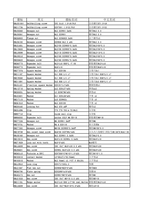
hex screw Selfdrilling screw washer Washer Hex nut Hex nut hex screw hex screw hex screw hex screw
KM231308 KM283347 KM280168 KM280169
M12*30 DIN933-8.8A3G M12 ST A2F 200HV ISO7089 M12 ST 8 A2F ISO4032 A12.5 DIN6798-A3G M12*35 DIN933-8.8A3B M10 DIN6923 A10 DIN127 M10*25 8.8 DIN933 M10*30 8.8 DIN933 M6 DIN934 8A3F M12*25 ST 8.8 A2F ISO4762
M12*110 KOS-L.47.05
膨胀螺栓M12*110
Expander bolt
M16*140
膨胀螺栓M16*140
Square washer
D14 DIN436
方垫片D14
Square washer
D14 KOS L44.17
方垫片D14 KOS-L44.17
Square washer
D14 KOS L44.17
Lock screw Wedge Anchor Socket screw
Lock screw Klemmschraube Washer
பைடு நூலகம்
746023G03
732234G03 732234G03 732234G03 732234G03 732234G03 732234G03 732234G03 732234G03 KM115238
英文
德标名词
中文名词
DIN2093标准翻译

蹀簧—质量规范—尺寸第二页①前言此标准由弹簧钢标产品准委员会制定②修订此标准与DIN2093:1992-01在以下方面有所不同:a)删除了弹簧垫圈命名的列子(见第4条)。
b)第4条中加入了按照holt比列对弹簧垫圈进行分级,A、B及C级。
c)在第7条中对新的数值Ft及压力6Ⅱ,6Ⅲ和6om。
d)此标准的修订充分考虑了标准的新式条款。
符号、单位和数量完全符合国际单位系统ISO31③之前版本DIN2093:1957-07, 1978-04, 1990-09, 1992-01第三页1. 范围此标准对蹀簧的材质、生产工艺、尺寸及公差进行了规定。
包括一些图标,来说明此类蹀簧允许的变动以及疲劳寿命。
此标准里列出的要求均是最低要求。
此标准包含三种尺寸系列的蹀簧。
2 引用标准以下所提及的文件对此文件的应用是不可或缺的。
凡注明日期的引用,只有引用的版本才可适用。
凡未注明日期的引用,只有最新版本的参考文献才可适用。
DIN2092:2006,蹀簧—计算DIN50969,高强度结构钢部件耐氢感应脆性断裂性,用支柱试验和预防性测量法进行检测DIN EN 1654,铜及铜合金—碟簧及连接器用带材DIN EN 10083-1,特殊钢淬火及回火的交货技术条件DIN EN 10083-2,非合金优质钢淬火及回火的交货技术条件DIN EN 10083-3,硼钢淬火及回火的交货技术条件DIN EN 10089,热轧钢淬火及回火的技术交货条件DIN EN 10132-4 冷轧窄钢带的热处理——交货技术状态——第4部分:弹簧钢及其他用途。
DIN EN 10151,不锈钢弹簧带材一般交货条件DIN EN ISO 3269,紧固件—接收检测DIN EN ISO 6507-1 金属材料—维氏硬度检测——第1部分:试验方法DIN EN ISO 6507-2 金属材料—维氏硬度检测——第2部分:试验仪器的检测与校准DIN EN ISO 6507-3金属材料—维氏硬度检测——第3部分:基准块的校准DIN EN ISO 6507-4金属材料—维氏硬度检测——第4部分:硬度值表DIN EN ISO 6507-4金属材料—洛氏硬度检测——第1部分:试验方法(A,B,C,D,E,F,G,H,K,N,T标尺)DIN EN ISO 6508-2 金属材料—洛氏硬度检测—第2部分:试验仪器的检测与校准(A,B,C,D,E,F,G,H,K,N,T标尺)DIN EN ISO 6508-3金属材料—洛氏硬度检测—第3部分:基准块的校准(A,B,C,D,E,F,G,H,K,N,T标尺)3 术语与定义碟簧是一种环形的锥形产品,适用于承载轴向荷载。
德标和国标,国际标准中英文对照表

德标和国标,国际标准中英文对照表序号德国标准中文品名英文品名国际标准中国标准Item DIN-Standard Description in Chinese Description in English ISO-Standard GB-Standard1 DIN1 圆锥销taper pins ISO2339 GB1172 DIN7 圆柱销parallel pins ISO2338 GB119-863 DIN84 开槽圆柱头螺钉slotted cheese head screws ISO1207 GB65-854 DIN85 开槽盘头螺钉slotted pan head screws ISO1580 GB67-855 DIN93 单耳止动垫圈tab washers GB8546 DIN94 开口销split cotter pins ISO1234 GB917 DIN95 开槽半沉头木螺钉slotted raised csk head wood screws GB1018 DIN96 开槽半圆头木螺钉slotted round head wood screws GB999 DIN97 开槽沉头木螺钉slotted countersunk head wood screws GB10010 DIN125-A 平垫plain washers ISO7089 GB97.1-8511 DIN125-B 平垫(带倒角) mediun washers ISO7090 GB97.2-8512 DIN126 平垫plain washers ISO709113 DIN127-A 重型弹垫spring lock washers,tang ends GB724414 DIN127-B 标准弹垫spring lock washers,square ends GB93-8715 DIN128-A 鞍形弹垫single coil spring lock washers GB7245-8716 DIN137-A 弹簧止动垫圈curved spring washers17 DIN137-B 波形弹垫wave spring washers GB95518 DIN186 T型方颈螺栓T-head bolts with square neck GB37-8819 DIN188 T型双接头螺栓T-head bolts with double nip20 DIN258 螺纹圆锥销taper pins with threaded end ISO873721 DIN261 T型头螺栓T-head bolts22 DIN315AF 蝶型螺母(美制) wing nuts amercia form23 DIN315DF 蝶型螺母(德制) wing nuts germany form GB62-8824 DIN316AF 蝶型螺钉(美制) wing screws amercia form25 DIN317DF 蝶型螺钉(德制) wing screws germany form26 DIN319 圆球型盖型螺母ball knobs27 DIN404 开槽带孔球面圆柱头螺钉slotted capstan screws GB832-8828 DIN417 开槽长圆柱端紧定螺钉slotted set srews with full dog point ISO7435 GB75-8529 DIN427 开槽平端紧定螺钉(半牙) slotted set srews with chamfered end ISO2342 GB73-8530 DIN431 小六角特薄细牙螺母pipe nuts with thread GB808-8831 DIN432 外舌止动垫圈external tap GB856-8832 DIN433 小垫圈(用于圆柱头螺钉) washers for cheese head screws ISO7092 GB848-9533 DIN434 方斜垫圈(U型) square taper washers for U-section GB852-8834 DIN435 方斜垫圈(I型) square taper washers for I-sections GB852-8835 DIN436 方垫圈square washers36 DIN438 开槽凹端紧定螺钉slotted set with cup point ISO7436 GB74-8537 DIN439 六角薄螺母hexagon thin nuts ISO4035 GB6172-8638 DIN439 细牙六角薄螺母hexagon thin nuts ISO8675 GB6173-8639 DIN440 木螺钉专用垫圈rounds washers for wood constructions ISO709440 DIN443 密封帽sealing caps,push-in type41 DIN444 活节螺栓B 型eye bolts form B GB798-8842 DIN462 内舌止动垫圈internal tab washers43 DIN463 双耳止动垫圈washers with two taps GB855-8844 DIN464 滚花高头螺钉knurled thumb screws with collar GB834-8845 DIN465 开槽滚花高头螺钉slotted knurled thumb screws with collar46 DIN466 滚花高螺母knurled thumb nuts with collar GB806-8847 DIN467 滚花薄螺母knurled thumb thin nuts GB807-8848 DIN470 锁紧垫圈sealing washers49 DIN471 轴用弹性挡圈retaining rings for shafts(external),circlips GB894.1-8650 DIN472 孔用弹性挡圈retaining rings for bores(internal),circlips GB893.1-8651 DIN478 方头带垫螺栓square head bolts with collar52 DIN479 方头圆柱底端螺栓square head bolts with half dog point53 DIN480 方头带垫半圆底端螺栓square head bolts with collar,half dog point and rounded end54 DIN508 T型槽螺母T-slot nuts ISO29955 DIN525 单头螺柱single end studs56 DIN529 地脚螺栓masonry bolts GB799-8857 DIN546 带槽圆螺母slotted round nuts GB817-7658 DIN547 端面带孔圆螺母round nuts with drilled holes in one face GB815-8859 DIN551 开槽平端紧定螺钉slotted sit screws with flat point ISO4776 GB73-8560 DIN553 开槽锥端紧定螺钉slotted set screws with cone point ISO7434 GB71-8561 DIN555 六角螺母hexagon nuts ISO403462 DIN557 方螺母-C square nuts GB39-8863 DIN558 六角头螺钉hexagon screws ISO401864 DIN561 六角头圆柱端紧定螺钉hexagon set screws with full dog point65 DIN562 薄型方螺母-B square nuts without bevel(pressed nuts)66 DIN571 六角头木螺钉hexagon head wood screws (coach screws) GB102-8667 DIN580 吊环螺钉lifting eye bolts ISO3266 GB825-7668 DIN582 吊环螺母lifting eye nuts69 DIN601 六角头螺栓hexagon bolts ISO401670 DIN603 大半圆头方颈螺栓(马车螺栓) mushroom head square neck bolts (carriage bolts) ISO8677 GB14-8871 DIN604 沉头带插销马车螺栓flat countersunk nib bolts72 DIN605 沉头长方颈马车螺栓flat countersunk long square neck bolts73 DIN607 半圆头带插销马车螺栓cup head nib bolts74 DIN608 沉头短方颈马车螺栓flat countersunk short square neck bolts75 DIN609 六角头精配螺栓(长螺纹)hexagon fitted bolts,long thread76 DIN610 六角头精配螺栓(短螺纹)hexagon fitted bolts,short thread77 DIN653 滚花平头螺钉knurled thumb screws thin type GB835-8878 DIN660 半圆头铆钉round head rivets ISO1051 GB867-8679 DIN661 沉头铆钉contersunk head rivets ISO1051 GB869-8680 DIN662 半沉头铆钉raised contersunk head rivets ISO105181 DIN674 大扁头铆钉mushroom head rivets ISO105182 DIN703 重型侧面带孔圆螺母adjusting rings,heavy range (shafting collars)83 DIN705 侧面带孔圆螺母adjusting rings,light range (shafting collars) GB816-8884 DIN741 卡头wire rope clips85 DIN787 T型槽螺钉T-slot screws ISO29986 DIN835 双头螺柱(牙长=2D)studs-metal (end=2d) GB900-8887 DIN906 内六角锥型闭锁螺钉hexagon socket pipe plugs,conical thread88 DIN908 内六角直型闭锁螺钉hexagon socket screw plugs,cyl. thread89 DIN909 外六角锥型闭锁螺钉hexagon head pipe plugs,conical thread90 DIN910 外六角直型闭锁螺钉hexagon head screw plugs,cyl.thread91 DIN911 内六角扳手socket wrenches ISO293692 DIN912 内六角圆柱头螺钉hexagon socket cap screws ISO4762 GB70-8593 DIN913 内六角平端紧定螺钉hexagon socket set screws with flat point ISO4026 GB77-8594 DIN914 内六角尖端紧定螺钉hexagon socket set screws with cone point ISO4027 GB78-8595 DIN915 内六角圆柱端紧定螺钉hexagon socket set screws with dog point ISO4028 GB79-8596 DIN916 内六角凹端紧定螺钉hexagon socket set screws with cup point ISO4029 GB80-8597 DIN917 薄型盲螺母hexagon cap nuts98 DIN920 开槽小圆柱头螺钉slotted short cheese head screws99 DIN921 开槽大圆柱头螺钉slotted large cheese head screws GB838-88100 DIN923 开槽圆柱头轴肩螺钉slotted pan head screws with shoulder GB830-88101 DIN927 开槽无头轴肩螺钉slotted shoulder screws102 DIN928 焊接方螺母square weld nuts GB/T13680-92103 DIN929 焊接六角螺母hexagon weld nuts GB/T13681-92104 DIN931 六角头螺栓(半牙)hexagon head screws ISO4014 GB5782-86105 DIN933 六角头螺栓(全牙)hexagon head screws ISO4017 GB5783-86106 DIN934 六角头螺母(1型) hexagon full nuts ISO4032 GB6170-86107 DIN934 细牙六角头螺母(1型) hexagon full nuts ISO8673 GB6171-86108 DIN935 开槽六角螺母hexagon slotted and castle nuts ISO7035 GB6178-86109 DIN936 六角头薄螺母hexagon thin nuts ISO4035 GB6172.1-86110 DIN937 六角头开槽薄螺母hexagon thin slotted and castle nuts ISO7038 GB6181-86111 DIN938 双头螺距(牙长=1D)studs metal (end=1d) GB897-88112 DIN939 双头螺距(牙长=1.25D)studs metal (end=1.25d) GB898-88113 DIN940 双头螺距(牙长=1.5D)studs metal (end=1.5d)114 DIN960 六角头细牙螺栓(半牙)hexagon head bolts,metric fine pitch thread ISO8765GB5785-86115 DIN961 六角头细牙螺栓(全牙)hexagon head bolts,metric fine pitch thread ISO8676GB5786-86116 DIN962 头部穿孔六角头螺栓additional shapes and versions for bolts117 DIN963 开槽沉头螺钉slotted countersund head screws ISO 2009 GB68-85118 DIN964 开槽半沉头螺钉slotted raised countersunk oval head screws ISO 2010 GB69-85119 DIN965 十字槽沉头螺钉cross recessed countersunk head screws ISO7046 GB819-85120 DIN966 十字槽半沉头螺钉cross recessed raised countersunk head screws ISO7047 GB820-85 121 DIN970 六角头螺母hexagon nuts type-1122 DIN971 六角头螺母hexagon nuts type-2123 DIN972 细牙六角头螺母(2型) hexagon nuts with fine thread ISO8674 GB6176-86124 DIN975 牙条(全螺纹) threaded rods(studdings) GB15389-94125 DIN976 螺纹销threaded pins(stud bolts)126 DIN979 六角头开槽薄螺母(2型)hexagon thin slotted and castle nuts127 DIN980 全金属六角锁紧螺母(1型)prevailling torque type hexagon nuts,all metall nuts ISO7199 GB6184-86128 DIN981 圆螺母locknuts ISO2982 GB812-88129 DIN982 六角头尼龙锁紧螺母prevailling torque type hexagon nuts,heavy type ,with nylon insert ISO7040 GB889.1-86130 DIN985 六角头薄型尼龙锁紧螺母prevailling torque type hexagon nuts,heavy type ,with nylon insert ISO10511 GB6172.2-86131 DIN986 六角盖型尼龙锁紧螺母prevailling torque typedomed capnuts with nylon insert132 DIN988 配合垫片shim rings133 DIN1052 木材连接用垫片washers for timber connectors134 DIN1151 沉头钢钉round plain head nails135 DIN1440 销钉专用垫片A型plain washers for clevis pins(A型) ISO8738136 DIN1441 销钉专用垫片plain washers for clevis pins137 DIN1444 带头销钉clevis pins with head ISO2341138 DIN1471 圆锥型槽销grooved pins,taper grooved ISO8744 GB/T13829.2139 DIN1472 圆锥型槽销(半槽) grooved pins,taper grooved half length ISO8745 GB/T13829.2140 DIN1473 平行槽销(带倒角) grooved pins,parallel grooved full length ISO8740141 DIN1474 前端凹槽槽销grooved pins,reserve grooved half length ISO8741142 DIN1475 中部凹槽槽销grooved pins,centre grooved ISO8742143 DIN1476 圆头槽销grooved pins with round head ISO8746 GB/T13829.3144 DIN1477 沉头槽销grooved pins with countersunk head ISO8747145 DIN1479 六角螺母棒turnuckles(centre parts),made out of hexagon bar146 DIN1480 花篮螺栓turnuckles with eye bolt and hook bolt147 DIN1481 弹性圆柱销spring pins,heavy type ISO8752 GB879-86148 DIN1587 组合式盖型螺母hexagon domed cap nuts GB802-88149 DIN1804 开槽圆螺母(配合沟头扳手)slotted round nuts for hook spanner150 DIN1816 圆螺母(带插销孔)round nuts with set holes151 DIN2093 盘型弹簧垫圈disc springs152 DIN3017 喉箍hose clamps153 DIN3404 润滑油嘴(旋扭头)lubricating nipples,button head154 DIN3567 管夹shackles for conduilts155 DIN3570 U型螺栓stirrup bolts(U-bolts)156 DIN6319 球面垫圈spherical washers,conical seats GB849-88157 DIN6325 圆柱销parallel pins ISO8734158 DIN6330 厚六角螺母hexagon nuts ,1.5d GB56-88159 DIN6331 厚六角法兰面螺母hexagon nuts ,1.5d with collar GB6177-86160 DIN6334 长六角螺母hexagon nuts ,3d161 DIN6797-A 外齿锁紧垫圈external teeth lock washers GB862.1-87162 DIN6797-I 内齿锁紧垫圈internal teeth lock washers GB861.1-87163 DIN6798-A 外锯齿锁紧垫圈external teeth serrated lock washers GB862.2-87164 DIN6798-I 内锯齿锁紧垫圈internal teeth serrated lock washers GB861.2-87165 DIN6799 开口挡圈retaining rings for shafts(E-rings),circlips GB896-76166 DIN6885 平键(A型)parallel keys(form A ) ISO773/2491167 DIN6888 半圆键woodruff keys ISO3912168 DIN6899 嵌环(支撑环)thimbles169 DIN6900 机器螺钉和垫圈组合件screws and washers assemblies GB9074.1-.17170 DIN6901 自攻螺钉和垫圈组合件tapping screws and washers assemblies GB9074.18-.23 171 DIN6912 薄型带孔内六角圆柱头螺钉hexagon socket head cap screws with hole,low head 172 DIN6914 大六角头螺栓hexagon head bolts with large head(friction grip bolts)173 DIN6915 大六角螺母hexagon nuts with large wideth across flat(friction grip nuts)174 DIN6916 大垫圈round washers for friction grip bolts175 DIN6917 楔型方垫圈spuare taper washers for friction grip bolts on T-sections176 DIN6923 六角法兰面螺母hexagon flange nuts ISO4161 GB6177-86177 DIN6925 全金属六角锁紧螺母(2型)prevailing torque type hexagon nuts,all metallic nuts ISO7042 GB6185.1-2000178 DIN7337 开口型抽芯铆钉(沉头、扁圆头)blind rivets GB12617/12618179 DIN7338 扁平头半空心/全空心铆钉rivets for brake and clutch lining GB875/975-86180 DIN7343 螺旋夹紧销spiral pins ISO8750181 DIN7346 轻型弹性圆柱销spring pins,light type ISO13337182 DIN7349 重型弹性圆柱销用垫圈washers for bolts with heavy type spring pinss183 DIN7500 ISO公制螺纹螺钉(多种头型) threadforming screws for ISO-metric thread184 DIN7504 自攻自钻螺钉(多种头型) self-drilling tapping screws185 DIN7513 开槽切削螺纹螺钉(多种头型) thread cutting screws186 DIN7516 十字槽切削螺纹螺钉(多种头型) thread cutting screws cross recess187 DIN7965 T型四爪螺母tee nuts with pronge188 DIN7968 钢结构用六角头螺栓连接副hexagon head fitted bolts for steel structuresGB1228/1229/1230189 DIN7971 开槽盘头自攻螺钉pan head tapping screws with slot ISO1481 GB5282-85190 DIN7972 开槽沉头自攻螺钉countersunk flat head tapping screws with slot ISO1482GB5283-85191 DIN7973 开槽半沉头自攻螺钉raised countersunk oval head tapping screws with slot ISO1483 GB5284-85192 DIN7976 六角头自攻螺钉hexagon tapping screws ISO1479 GB5285-85193 DIN7980 圆柱头螺钉用弹簧垫圈spring lock washers for screws with cylindrical heads ISO8738 194 DIN7981 十字槽盘头自攻螺钉pan head tapping screws with cross recessed ISO 7049GB845-85195 DIN7982 十字槽沉头自攻螺钉countersunk flat head tapping screws with cross recessedISO7050 GB846-85196 DIN7983 十字槽半沉头自攻螺钉raised countersunk oval head tapping screws with cross recessed ISO7051 GB847-86197 DIN7984 薄型内六角圆柱头螺钉hexagon socket head cap screws with,reduced head198 DIN7985 十字槽盘头螺钉pan head screws with cross recessed ISO7045 GB818-85199 DIN7989 钢结构用垫圈washers for steel structures GB1230-84200 DIN7990 钢结构用六角头螺栓hexagon head bolts for steel structures GB1229-84201 DIN7991 内六角沉头螺钉hexagon socket countersunk head screws ISO10642202 DIN7993 轴用钢丝挡圈roundwire snap rings for shafts GB895.2-86203 DIN7995 十字槽半沉头木螺钉cross recessed raised countersunk head wood screws GB952-86 204 DIN7996 十字槽圆头木螺钉cross recessed round head wood screws GB950-86205 DIN7997 十字槽沉头木螺钉cross recessed countersunk head wood screws GB951-86206 DIN8140 螺纹护套(普通\自锁等)ciol inserts,coarse,fine thread,silf locking207 DIN9021 大外径垫圈washers,outside diameter appro.3d ISO7093 GB96-85208 DIN11024 弹簧卡子spring cotter for a bolt209 DIN13257 平板螺栓belting bolts (elevator bolts)210 DIN18182 干壁钉(墙板钉)dry wall screws211 DIN28129 环型螺母lifting nuts(eye nuts) GB63-88212 DIN70952 圆螺母用止退垫圈tab washers for slotted round nuts GB858-88。
德国标准和国际标准、中国标准中英文对照表(紧固件)
德国标准和国际标准、中国标准中英文对照表序号德国标准中文品名英文品名国际标准中国标准Item DIN-Standard Description in Chinese Description in English ISO-Standard GB-Standard1 DIN1 圆锥销taper pins ISO2339 GB1172 DIN7 圆柱销parallel pins ISO2338 GB119-863 DIN84 开槽圆柱头螺钉slotted cheese head screws ISO1207 GB65-854 DIN85 开槽盘头螺钉slotted pan head screws ISO1580 GB67-855 DIN93 单耳止动垫圈tab washers GB8546 DIN94 开口销split cotter pins ISO1234 GB917 DIN95 开槽半沉头木螺钉slotted raised csk head wood screws GB1018 DIN96 开槽半圆头木螺钉slotted round head wood screws GB999 DIN97 开槽沉头木螺钉slotted countersunk head wood screws GB10010 DIN125-A 平垫plain washers ISO7089 GB97.1-8511 DIN125-B 平垫(带倒角) mediun washers ISO7090 GB97.2-8512 DIN126 平垫plain washers ISO709113 DIN127-A 重型弹垫spring lock washers,tang ends GB724414 DIN127-B 标准弹垫spring lock washers,square ends GB93-8715 DIN128-A 鞍形弹垫single coil spring lock washers GB7245-8716 DIN137-A 弹簧止动垫圈curved spring washers17 DIN137-B 波形弹垫wave spring washers GB95518 DIN186 T型方颈螺栓T-head bolts with square neck GB37-8819 DIN188 T型双接头螺栓T-head bolts with double nip20 DIN258 螺纹圆锥销taper pins with threaded end ISO873721 DIN261 T型头螺栓T-head bolts22 DIN315AF 蝶型螺母(美制) wing nuts amercia form23 DIN315DF 蝶型螺母(德制) wing nuts germany form GB62-8824 DIN316AF 蝶型螺钉(美制) wing screws amercia form25 DIN317DF 蝶型螺钉(德制) wing screws germany form26 DIN319 圆球型盖型螺母ball knobs27 DIN404 开槽带孔球面圆柱头螺钉slotted capstan screws GB832-8828 DIN417 开槽长圆柱端紧定螺钉slotted set srews with full dog point ISO7435 GB75-8529 DIN427 开槽平端紧定螺钉(半牙) slotted set srews with chamfered end ISO2342 GB73-8530 DIN431 小六角特薄细牙螺母pipe nuts with thread GB808-8831 DIN432 外舌止动垫圈external tap GB856-8832 DIN433 小垫圈(用于圆柱头螺钉) washers for cheese head screws ISO7092 GB848-9533 DIN434 方斜垫圈(U型) square taper washers for U-section GB852-8834 DIN435 方斜垫圈(I型) square taper washers for I-sections GB852-8835 DIN436 方垫圈square washers36 DIN438 开槽凹端紧定螺钉slotted set with cup point ISO7436 GB74-8537 DIN439 六角薄螺母hexagon thin nuts ISO4035 GB6172-8638 DIN439 细牙六角薄螺母hexagon thin nuts ISO8675 GB6173-8639 DIN440 木螺钉专用垫圈rounds washers for wood constructions ISO709440 DIN443 密封帽sealing caps,push-in type41 DIN444 活节螺栓B 型eye bolts form B GB798-8842 DIN462 内舌止动垫圈internal tab washers43 DIN463 双耳止动垫圈washers with two taps GB855-8844 DIN464 滚花高头螺钉knurled thumb screws with collar GB834-8845 DIN465 开槽滚花高头螺钉slotted knurled thumb screws with collar46 DIN466 滚花高螺母knurled thumb nuts with collar GB806-8847 DIN467 滚花薄螺母knurled thumb thin nuts GB807-8848 DIN470 锁紧垫圈sealing washers49 DIN471 轴用弹性挡圈retaining rings for shafts(external),circlips GB894.1-8650 DIN472 孔用弹性挡圈retaining rings for bores(internal),circlips GB893.1-8651 DIN478 方头带垫螺栓square head bolts with collar52 DIN479 方头圆柱底端螺栓square head bolts with half dog point53 DIN480 方头带垫半圆底端螺栓square head bolts with collar,half dog point and rounded end54 DIN508 T型槽螺母T-slot nuts ISO29955 DIN525 单头螺柱single end studs56 DIN529 地脚螺栓masonry bolts GB799-8857 DIN546 带槽圆螺母slotted round nuts GB817-7658 DIN547 端面带孔圆螺母round nuts with drilled holes in one face GB815-8859 DIN551 开槽平端紧定螺钉slotted sit screws with flat point ISO4776 GB73-8560 DIN553 开槽锥端紧定螺钉slotted set screws with cone point ISO7434 GB71-8561 DIN555 六角螺母hexagon nuts ISO403462 DIN557 方螺母-C square nuts GB39-8863 DIN558 六角头螺钉hexagon screws ISO401864 DIN561 六角头圆柱端紧定螺钉hexagon set screws with full dog point65 DIN562 薄型方螺母-B square nuts without bevel(pressed nuts)66 DIN571 六角头木螺钉hexagon head wood screws (coach screws) GB102-8667 DIN580 吊环螺钉lifting eye bolts ISO3266 GB825-7668 DIN582 吊环螺母lifting eye nuts69 DIN601 六角头螺栓hexagon bolts ISO401670 DIN603 大半圆头方颈螺栓(马车螺栓) mushroom head square neck bolts (carriage bolts) ISO8677 GB14-8871 DIN604 沉头带插销马车螺栓flat countersunk nib bolts72 DIN605 沉头长方颈马车螺栓flat countersunk long square neck bolts73 DIN607 半圆头带插销马车螺栓cup head nib bolts74 DIN608 沉头短方颈马车螺栓flat countersunk short square neck bolts75 DIN609 六角头精配螺栓(长螺纹)hexagon fitted bolts,long thread76 DIN610 六角头精配螺栓(短螺纹)hexagon fitted bolts,short thread77 DIN653 滚花平头螺钉knurled thumb screws thin type GB835-8878 DIN660 半圆头铆钉round head rivets ISO1051 GB867-8679 DIN661 沉头铆钉contersunk head rivets ISO1051 GB869-8680 DIN662 半沉头铆钉raised contersunk head rivets ISO105181 DIN674 大扁头铆钉mushroom head rivets ISO105182 DIN703 重型侧面带孔圆螺母adjusting rings,heavy range (shafting collars)83 DIN705 侧面带孔圆螺母adjusting rings,light range (shafting collars) GB816-8884 DIN741 卡头wire rope clips85 DIN787 T型槽螺钉T-slot screws ISO29986 DIN835 双头螺柱(牙长=2D)studs-metal (end=2d) GB900-8887 DIN906 内六角锥型闭锁螺钉hexagon socket pipe plugs,conical thread88 DIN908 内六角直型闭锁螺钉hexagon socket screw plugs,cyl. thread89 DIN909 外六角锥型闭锁螺钉hexagon head pipe plugs,conical thread90 DIN910 外六角直型闭锁螺钉hexagon head screw plugs,cyl.thread91 DIN911 内六角扳手socket wrenches ISO293692 DIN912 内六角圆柱头螺钉hexagon socket cap screws ISO4762 GB70-8593 DIN913 内六角平端紧定螺钉hexagon socket set screws with flat point ISO4026 GB77-8594 DIN914 内六角尖端紧定螺钉hexagon socket set screws with cone point ISO4027 GB78-8595 DIN915 内六角圆柱端紧定螺钉hexagon socket set screws with dog point ISO4028 GB79-8596 DIN916 内六角凹端紧定螺钉hexagon socket set screws with cup point ISO4029 GB80-8597 DIN917 薄型盲螺母hexagon cap nuts98 DIN920 开槽小圆柱头螺钉slotted short cheese head screws99 DIN921 开槽大圆柱头螺钉slotted large cheese head screws GB838-88100 DIN923 开槽圆柱头轴肩螺钉slotted pan head screws with shoulder GB830-88101 DIN927 开槽无头轴肩螺钉slotted shoulder screws102 DIN928 焊接方螺母square weld nuts GB/T13680-92103 DIN929 焊接六角螺母hexagon weld nuts GB/T13681-92104 DIN931 六角头螺栓(半牙)hexagon head screws ISO4014 GB5782-86105 DIN933 六角头螺栓(全牙)hexagon head screws ISO4017 GB5783-86106 DIN934 六角头螺母(1型) hexagon full nuts ISO4032 GB6170-86107 DIN934 细牙六角头螺母(1型) hexagon full nuts ISO8673 GB6171-86108 DIN935 开槽六角螺母hexagon slotted and castle nuts ISO7035 GB6178-86109 DIN936 六角头薄螺母hexagon thin nuts ISO4035 GB6172.1-86110 DIN937 六角头开槽薄螺母hexagon thin slotted and castle nuts ISO7038 GB6181-86111 DIN938 双头螺距(牙长=1D)studs metal (end=1d) GB897-88112 DIN939 双头螺距(牙长=1.25D)studs metal (end=1.25d) GB898-88113 DIN940 双头螺距(牙长=1.5D)studs metal (end=1.5d)114 DIN960 六角头细牙螺栓(半牙)hexagon head bolts,metric fine pitch thread ISO8765 GB5785-86115 DIN961 六角头细牙螺栓(全牙)hexagon head bolts,metric fine pitch thread ISO8676 GB5786-86116 DIN962 头部穿孔六角头螺栓additional shapes and versions for bolts117 DIN963 开槽沉头螺钉slotted countersund head screws ISO 2009 GB68-85118 DIN964 开槽半沉头螺钉slotted raised countersunk oval head screws ISO 2010 GB69-85 119 DIN965 十字槽沉头螺钉cross recessed countersunk head screws ISO7046 GB819-85120 DIN966 十字槽半沉头螺钉cross recessed raised countersunk head screws ISO7047 GB820-85121 DIN970 六角头螺母hexagon nuts type-1122 DIN971 六角头螺母hexagon nuts type-2123 DIN972 细牙六角头螺母(2型) hexagon nuts with fine thread ISO8674 GB6176-86124 DIN975 牙条(全螺纹) threaded rods(studdings) GB15389-94125 DIN976 螺纹销threaded pins(stud bolts)126 DIN979 六角头开槽薄螺母(2型)hexagon thin slotted and castle nuts127 DIN980 全金属六角锁紧螺母(1型)prevailling torque type hexagon nuts,all metall nuts ISO7199 GB6184-86128 DIN981 圆螺母locknuts ISO2982 GB812-88129 DIN982 六角头尼龙锁紧螺母prevailling torque type hexagon nuts,heavy type ,with nylon insert ISO7040 GB889.1-86130 DIN985 六角头薄型尼龙锁紧螺母prevailling torque type hexagon nuts,heavy type ,with nylon insert ISO10511 GB6172.2-86131 DIN986 六角盖型尼龙锁紧螺母prevailling torque typedomed capnuts with nylon insert132 DIN988 配合垫片shim rings133 DIN1052 木材连接用垫片washers for timber connectors134 DIN1151 沉头钢钉round plain head nails135 DIN1440 销钉专用垫片A型plain washers for clevis pins(A型) ISO8738136 DIN1441 销钉专用垫片plain washers for clevis pins137 DIN1444 带头销钉clevis pins with head ISO2341138 DIN1471 圆锥型槽销grooved pins,taper grooved ISO8744 GB/T13829.2139 DIN1472 圆锥型槽销(半槽) grooved pins,taper grooved half length ISO8745 GB/T13829.2 140 DIN1473 平行槽销(带倒角) grooved pins,parallel grooved full length ISO8740141 DIN1474 前端凹槽槽销grooved pins,reserve grooved half length ISO8741142 DIN1475 中部凹槽槽销grooved pins,centre grooved ISO8742143 DIN1476 圆头槽销grooved pins with round head ISO8746 GB/T13829.3144 DIN1477 沉头槽销grooved pins with countersunk head ISO8747145 DIN1479 六角螺母棒turnuckles(centre parts),made out of hexagon bar146 DIN1480 花篮螺栓turnuckles with eye bolt and hook bolt147 DIN1481 弹性圆柱销spring pins,heavy type ISO8752 GB879-86148 DIN1587 组合式盖型螺母hexagon domed cap nuts GB802-88149 DIN1804 开槽圆螺母(配合沟头扳手)slotted round nuts for hook spanner150 DIN1816 圆螺母(带插销孔)round nuts with set holes151 DIN2093 盘型弹簧垫圈disc springs152 DIN3017 喉箍hose clamps153 DIN3404 润滑油嘴(旋扭头)lubricating nipples,button head154 DIN3567 管夹shackles for conduilts155 DIN3570 U型螺栓stirrup bolts(U-bolts)156 DIN6319 球面垫圈spherical washers,conical seats GB849-88157 DIN6325 圆柱销parallel pins ISO8734158 DIN6330 厚六角螺母hexagon nuts ,1.5d GB56-88159 DIN6331 厚六角法兰面螺母hexagon nuts ,1.5d with collar GB6177-86160 DIN6334 长六角螺母hexagon nuts ,3d161 DIN6797-A 外齿锁紧垫圈external teeth lock washers GB862.1-87162 DIN6797-I 内齿锁紧垫圈internal teeth lock washers GB861.1-87163 DIN6798-A 外锯齿锁紧垫圈external teeth serrated lock washers GB862.2-87164 DIN6798-I 内锯齿锁紧垫圈internal teeth serrated lock washers GB861.2-87165 DIN6799 开口挡圈retaining rings for shafts(E-rings),circlips GB896-76166 DIN6885 平键(A型)parallel keys(form A ) ISO773/2491167 DIN6888 半圆键woodruff keys ISO3912168 DIN6899 嵌环(支撑环)thimbles169 DIN6900 机器螺钉和垫圈组合件screws and washers assemblies GB9074.1-.17170 DIN6901 自攻螺钉和垫圈组合件tapping screws and washers assemblies GB9074.18-.23 171 DIN6912 薄型带孔内六角圆柱头螺钉hexagon socket head cap screws with hole,low head 172 DIN6914 大六角头螺栓hexagon head bolts with large head(friction grip bolts)173 DIN6915 大六角螺母hexagon nuts with large wideth across flat(friction grip nuts)174 DIN6916 大垫圈round washers for friction grip bolts175 DIN6917 楔型方垫圈spuare taper washers for friction grip bolts on T-sections176 DIN6923 六角法兰面螺母hexagon flange nuts ISO4161 GB6177-86177 DIN6925 全金属六角锁紧螺母(2型)prevailing torque type hexagon nuts,all metallic nuts ISO7042 GB6185.1-2000178 DIN7337 开口型抽芯铆钉(沉头、扁圆头)blind rivets GB12617/12618179 DIN7338 扁平头半空心/全空心铆钉rivets for brake and clutch lining GB875/975-86180 DIN7343 螺旋夹紧销spiral pins ISO8750181 DIN7346 轻型弹性圆柱销spring pins,light type ISO13337182 DIN7349 重型弹性圆柱销用垫圈washers for bolts with heavy type spring pinss183 DIN7500 ISO公制螺纹螺钉(多种头型) threadforming screws for ISO-metric thread184 DIN7504 自攻自钻螺钉(多种头型) self-drilling tapping screws185 DIN7513 开槽切削螺纹螺钉(多种头型) thread cutting screws186 DIN7516 十字槽切削螺纹螺钉(多种头型) thread cutting screws cross recess187 DIN7965 T型四爪螺母tee nuts with pronge188 DIN7968 钢结构用六角头螺栓连接副hexagon head fitted bolts for steel structures GB1228/1229/1230189 DIN7971 开槽盘头自攻螺钉pan head tapping screws with slot ISO1481 GB5282-85190 DIN7972 开槽沉头自攻螺钉countersunk flat head tapping screws with slot ISO1482 GB5283-85191 DIN7973 开槽半沉头自攻螺钉raised countersunk oval head tapping screws with slot ISO1483 GB5284-85192 DIN7976 六角头自攻螺钉hexagon tapping screws ISO1479 GB5285-85193 DIN7980 圆柱头螺钉用弹簧垫圈spring lock washers for screws with cylindrical heads ISO8738194 DIN7981 十字槽盘头自攻螺钉pan head tapping screws with cross recessed ISO 7049 GB845-85195 DIN7982 十字槽沉头自攻螺钉countersunk flat head tapping screws with cross recessed ISO7050 GB846-85196 DIN7983 十字槽半沉头自攻螺钉raised countersunk oval head tapping screws with cross recessed ISO7051 GB847-86197 DIN7984 薄型内六角圆柱头螺钉hexagon socket head cap screws with,reduced head198 DIN7985 十字槽盘头螺钉pan head screws with cross recessed ISO7045 GB818-85199 DIN7989 钢结构用垫圈washers for steel structures GB1230-84200 DIN7990 钢结构用六角头螺栓hexagon head bolts for steel structures GB1229-84201 DIN7991 内六角沉头螺钉hexagon socket countersunk head screws ISO10642202 DIN7993 轴用钢丝挡圈roundwire snap rings for shafts GB895.2-86203 DIN7995 十字槽半沉头木螺钉cross recessed raised countersunk head wood screws GB952-86204 DIN7996 十字槽圆头木螺钉cross recessed round head wood screws GB950-86205 DIN7997 十字槽沉头木螺钉cross recessed countersunk head wood screws GB951-86206 DIN8140 螺纹护套(普通\自锁等)ciol inserts,coarse,fine thread,silf locking207 DIN9021 大外径垫圈washers,outside diameter appro.3d ISO7093 GB96-85208 DIN11024 弹簧卡子spring cotter for a bolt209 DIN13257 平板螺栓belting bolts (elevator bolts)210 DIN18182 干壁钉(墙板钉)dry wall screws211 DIN28129 环型螺母lifting nuts(eye nuts) GB63-88212 DIN70952 圆螺母用止退垫圈tab washers for slotted round nuts GB858-88。
碟形弹簧——精选推荐
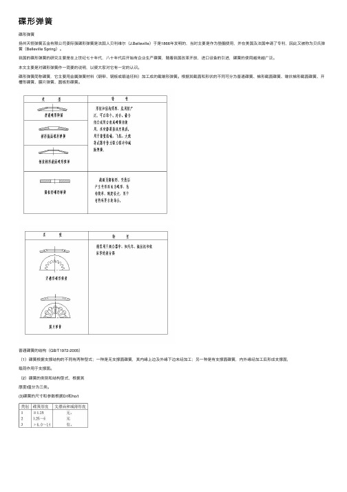
碟形弹簧碟形弹簧扬州天恒弹簧五⾦有限公司姜际强碟形弹簧是法国⼈贝利维尔(J.Belleville)于是1866年发明的,当时主要是作为垫圈使⽤,并在美国及法国申请了专利,因此⼜被称为贝⽒弹簧(Belleville Spring)。
我国的碟形弹簧的研究主要是在上世纪七⼗年代,⼋⼗年代后开始有企业⽣产碟簧,随着我国改⾰开放,进⼝设备的引进,碟簧的使⽤越来越⼴泛。
本⽂主要是对碟形弹簧作⼀简要的说明,以便⼤家对它有⼀定的认识。
碟形弹簧简称碟簧,它主要⽤⾦属弹簧材料(钢带、钢板或锻造坯料)加⼯成的截锥形弹簧。
根据其截⾯和形状的不同可分为普通碟簧、梯形截⾯碟簧、锥状梯形截⾯碟簧、开槽形碟簧、膜⽚弹簧、圆板形碟簧。
普通碟簧的结构(GB/T1972-2005)(1)碟簧根据⽀撑结构的不同有两种型式;⼀种是⽆⽀撑⾯碟簧,其内缘上边及外缘下边未经加⼯;另⼀种是有⽀撑⾯碟簧,内外缘经加⼯后形成⽀撑⾯,载荷作⽤于⽀撑⾯。
(2)碟簧的类别和结构型式,根据其厚度t值分为三类。
(3)碟簧的尺⼨和参数根据D/t和ho/t值分为A(D/t≈18,ho/t≈0.4)、B(D/t≈28,ho/t≈0.75)、C(D/ho≈40,ho/t≈1.3)三个系列碟簧的主要特点与应⽤碟簧与其它型式的弹簧如螺旋弹簧、钢板弹簧等⽐较,其主要特点如下:⑴轴向尺⼨较⼩⽽径向尺⼨较⼤它能在很⼩的的变形条件下,承受变化范围很⼤的轴向载荷,其单位体积的变形能较⼤,具有较好的缓冲吸振能⼒,因此适合轴向空间⼩,径向空间⼤⽽承载⼤的场合。
⑵具有变刚性的特性在外径和内径尺⼨相同的条件下,只要改变碟簧厚度与碟簧的内锥⾼度之⽐可以得到不同的弹簧特性曲线,z=ho/t﹤2,是正刚度(刚度⼤)z=0.2~1.3;z=ho/t≈2是正刚度+零刚度z=1.3~1.5; 2﹤ho/t﹤22是正刚度+负刚度z=1.5~2.3;z﹥22是正刚度+负刚度z﹥2.8。
在国标中的碟簧是采⽤z﹤2的。
德国DIN标准件ISO及国标对照表
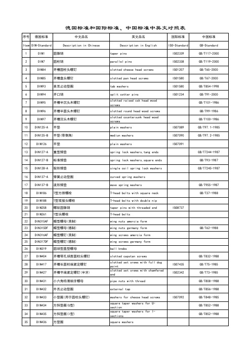
序号德国标准中文品名英文品名国际标准中国标准Item DIN-Standard Description in Chinese Description in English ISO-Standard GB-Standard 1DIN1圆锥销taper pins ISO2339GB/T117-2000 2DIN7圆柱销parallel pins ISO2338GB/T119-2000 3DIN84开槽圆柱头螺钉slotted cheese head screws ISO1207GB/T65-2000 4DIN85开槽盘头螺钉slotted pan head screws ISO1580GB/T67-2000 5DIN93单耳止动垫圈tab washers ISO1580GB/T854-1998 6DIN94开口销split cotter pins ISO1234GB/T91-20007DIN95开槽半沉头木螺钉slotted raised csk head woodscrewsGB/T101-19868DIN96开槽半圆头木螺钉slotted round head wood screws GB/T99-19869DIN97开槽沉头木螺钉slotted countersunk head woodscrewsGB/T100-198610DIN125-A平垫plain washers ISO7089GB/T97.1-1985 11DIN125-B平垫(带倒角)mediun washers ISO7090GB/T97.2-1985 12DIN126平垫plain washers ISO709113DIN127-A重型弹垫spring lock washers,tang ends GB/T7244-1987 14DIN127-B标准弹垫spring lock washers,square ends GB/T93-1987 15DIN128-A鞍形弹垫single coil spring lock washers GB/T7245-1987 16DIN137-A弹簧止动垫圈curved spring washers17DIN137-B波形弹垫wave spring washers GB/T955-1987 18DIN186T型方颈螺栓T-head bolts with square neck GB/T37-1988 19DIN188T型双接头螺栓T-head bolts with double nip20DIN258螺纹圆锥销taper pins with threaded end ISO873721DIN261T型头螺栓T-head bolts22DIN315AF蝶型螺母(美制)wing nuts amercia form23DIN315DF蝶型螺母(德制)wing nuts germany form GB/T62-1988 24DIN316AF蝶型螺钉(美制)wing screws amercia form25DIN317DF蝶型螺钉(德制)wing screws germany form26DIN319圆球型盖型螺母ball knobs27DIN404开槽带孔球面圆柱头螺钉slotted capstan screws GB/T832-198828DIN417开槽长圆柱端紧定螺钉slotted set srews with full dogpointISO7435GB/T75-198529DIN427开槽平端紧定螺钉(半牙)slotted set srews with chamferedendISO2342GB/T73-198530DIN431小六角特薄细牙螺母pipe nuts with thread GB/T808-1988 31DIN432外舌止动垫圈external tap GB/T856-1988 32DIN433小垫圈(用于圆柱头螺钉)washers for cheese head screws ISO7092GB/T848-198533DIN434方斜垫圈(U型)square taper washers for U-sectionGB/T852-198834DIN435方斜垫圈(I型)square taper washers for I-sectionsGB/T852-198835DIN436方垫圈square washers序号德国标准中文品名英文品名国际标准中国标准Item DIN-Standard Description in Chinese Description in English ISO-Standard GB-Standard 36DIN438开槽凹端紧定螺钉slotted set with cup point ISO7436GB/T74-1985 37DIN439六角薄螺母hexagon thin nuts ISO4035GB/T6172-2000 38DIN439细牙六角薄螺母hexagon thin nuts ISO8675GB/T6173-200039DIN440木螺钉专用垫圈rounds washers for woodconstructionsISO709440DIN443密封帽sealing caps,push-in type41DIN444活节螺栓B 型eye bolts form B GB/T798-1988 42DIN462内舌止动垫圈internal tab washers43DIN463双耳止动垫圈washers with two taps GB/T855-1988 44DIN464滚花高头螺钉knurled thumb screws with collar GB/T834-198845DIN465开槽滚花高头螺钉slotted knurled thumb screws with collar46DIN466滚花高螺母knurled thumb nuts with collar GB/T806-1988 47DIN467滚花薄螺母knurled thumb thin nuts GB/T807-1988 48DIN470锁紧垫圈sealing washers49DIN471轴用弹性挡圈retaining rings forshafts(external),circlipsGB/T894.1-198650DIN472孔用弹性挡圈retaining rings forbores(internal),circlipsGB/T893.1-198651DIN478方头带垫螺栓square head bolts with collar52DIN479方头圆柱底端螺栓square head bolts with half dog point53DIN480方头带垫半圆底端螺栓square head bolts withcollar,half dog point and rounded54DIN508T型槽螺母T-slot nuts ISO29955DIN525单头螺柱single end studs56DIN529地脚螺栓masonry bolts GB/T799-1988 57DIN546带槽圆螺母slotted round nuts GB/T817-198858DIN547端面带孔圆螺母round nuts with drilled holes inone faceGB/T815-198859DIN551开槽平端紧定螺钉slotted sit screws with flatpointISO4776GB/T73-198560DIN553开槽锥端紧定螺钉slotted set screws with conepointISO7434GB/T71-198561DIN555六角螺母hexagon nuts ISO403462DIN557方螺母-C square nuts GB/T39-1988 63DIN558六角头螺钉hexagon screws ISO401864DIN561六角头圆柱端紧定螺钉hexagon set screws with full dog point65DIN562薄型方螺母-B square nuts without bevel(pressed nuts)66DIN571六角头木螺钉hexagon head wood screws (coachscrews)GB/T102-198667DIN580吊环螺钉lifting eye bolts ISO3266GB/T825-1988 68DIN582吊环螺母lifting eye nuts69DIN601六角头螺栓hexagon bolts ISO4016序号德国标准中文品名英文品名国际标准中国标准Item DIN-Standard Description in Chinese Description in English ISO-Standard GB-Standard70DIN603大半圆头方颈螺栓(马车螺栓)mushroom head square neck bolts(carriage bolts)ISO8677GB/T14-198871DIN604沉头带插销马车螺栓flat countersunk nib bolts72DIN605沉头长方颈马车螺栓flat countersunk long square neck bolts73DIN607半圆头带插销马车螺栓cup head nib bolts74DIN608沉头短方颈马车螺栓flat countersunk short square neck bolts75DIN609六角头精配螺栓(长螺纹)hexagon fitted bolts,long thread76DIN610六角头精配螺栓(短螺纹)hexagon fitted bolts,short thread77DIN653滚花平头螺钉knurled thumb screws thin type GB/T835-1988 78DIN660半圆头铆钉round head rivets ISO1051GB/T867-1986 79DIN661沉头铆钉contersunk head rivets ISO1051GB/T869-1986 80DIN662半沉头铆钉raised contersunk head rivets ISO105181DIN674大扁头铆钉mushroom head rivets ISO105182DIN703重型侧面带孔圆螺母adjusting rings,heavy range (shafting collars)83DIN705侧面带孔圆螺母adjusting rings,light range(shafting collars)GB/T816-198884DIN741卡头wire rope clips85DIN787T型槽螺钉T-slot screws ISO29986DIN835双头螺柱(牙长=2D)studs-metal (end=2d)GB/T900-198887DIN906内六角锥型闭锁螺钉hexagon socket pipe plugs,conical thread88DIN908内六角直型闭锁螺钉hexagon socket screw plugs,cyl. thread89DIN909外六角锥型闭锁螺钉hexagon head pipe plugs,conical thread90DIN910外六角直型闭锁螺钉hexagon head screw plugs,cyl.thread91DIN911内六角扳手socket wrenches ISO293692DIN912内六角圆柱头螺钉hexagon socket cap screws ISO4762GB/T70-200093DIN913内六角平端紧定螺钉hexagon socket set screws withflat pointISO4026GB/T77-200094DIN914内六角尖端紧定螺钉hexagon socket set screws withcone pointISO4027GB/T78-200095DIN915内六角圆柱端紧定螺钉hexagon socket set screws withdog pointISO4028GB/T79-200096DIN916内六角凹端紧定螺钉hexagon socket set screws withcup pointISO4029GB/T80-200097DIN917薄型盲螺母hexagon cap nuts98DIN920开槽小圆柱头螺钉slotted short cheese head screws99DIN921开槽大圆柱头螺钉slotted large cheese head screws GB/T838-1988100DIN923开槽圆柱头轴肩螺钉slotted pan head screws withshoulderGB/T830-1988101DIN927开槽无头轴肩螺钉slotted shoulder screws102DIN928焊接方螺母square weld nuts GB/T13680-1992 103DIN929焊接六角螺母hexagon weld nuts GB/T13681-1992序号德国标准中文品名英文品名国际标准中国标准Item DIN-Standard Description in Chinese Description in English ISO-Standard GB-Standard 104DIN931六角头螺栓(半牙)hexagon head screws ISO4014GB/T5782-2000 105DIN933六角头螺栓(全牙)hexagon head screws ISO4017GB/T5783-2000 106DIN934六角头螺母(1型)hexagon full nuts ISO4032GB/T6170-2000 107DIN934细牙六角头螺母(1型)hexagon full nuts ISO8673GB/T6171-2000 108DIN935开槽六角螺母hexagon slotted and castle nuts ISO7035GB/T6178-1986 109DIN936六角头薄螺母hexagon thin nuts ISO4035GB/T6172.1-2000110DIN937六角头开槽薄螺母hexagon thin slotted and castlenutsISO7038GB/T6181-1986111DIN938双头螺柱(牙长=1D)studs metal (end=1d)GB/T897-1988 112DIN939双头螺柱(牙长=1.25D)studs metal (end=1.25d)GB/T898-1988 113DIN940双头螺柱(牙长=1.5D)studs metal (end=1.5d)114DIN960六角头细牙螺栓(半牙)hexagon head bolts,metric finepitch threadISO8765GB/T5785-2000115DIN961六角头细牙螺栓(全牙)hexagon head bolts,metric finepitch threadISO8676GB/T5786-2000116DIN962头部穿孔六角头螺栓additional shapes and versions for bolts117DIN963开槽沉头螺钉slotted countersund head screws ISO 2009GB/T68-2000118DIN964开槽半沉头螺钉slotted raised countersunk ovalhead screwsISO 2010GB/T69-2000119DIN965十字槽沉头螺钉cross recessed countersunk headscrewsISO7046GB/T819.1-2000GB/T819.2-1997120DIN966十字槽半沉头螺钉cross recessed raised countersunkhead screwsISO7047GB/T820-2000121DIN970六角头螺母hexagon nuts type-1122DIN971六角头螺母hexagon nuts type-2123DIN972细牙六角头螺母(2型)hexagon nuts with fine thread ISO8674GB/T6176-2000 124DIN975牙条(全螺纹)threaded rods(studdings)GB/T15389-94 125DIN976螺纹销threaded pins(stud bolts)126DIN979六角头开槽薄螺母(2型)hexagon thin slotted and castle nuts127DIN980全金属六角锁紧螺母(1型)prevailling torque type hexagonnuts,all metall nutsISO7199GB/T6184-2000128DIN981圆螺母locknuts ISO2982GB/T812-1988129DIN982六角头尼龙锁紧螺母prevailling torque type hexagonnuts,heavy type ,with nylonISO7040GB/T889.1-2000130DIN985六角头薄型尼龙锁紧螺母prevailling torque type hexagonnuts,heavy type ,with nylonISO10511GB/T6172.2-2000131DIN986六角盖型尼龙锁紧螺母prevailling torque typedomed capnuts with nylon insert132DIN988配合垫片shim rings133DIN1052木材连接用垫片washers for timber connectors 134DIN1151沉头钢钉round plain head nails135DIN1440销钉专用垫片A型plain washers for clevis pins(A型)ISO8738136DIN1441销钉专用垫片plain washers for clevis pins137DIN1444带头销钉clevis pins with head ISO2341序号德国标准中文品名英文品名国际标准中国标准Item DIN-Standard Description in Chinese Description in English ISO-Standard GB-Standard 138DIN1471圆锥型槽销grooved pins,taper grooved ISO8744GB/T13829.2-92139DIN1472圆锥型槽销(半槽)grooved pins,taper grooved halflengthISO8745GB/T13829.2-92140DIN1473平行槽销(带倒角)grooved pins,parallel groovedfull lengthISO8740141DIN1474前端凹槽槽销grooved pins,reserve grooved halflengthISO8741142DIN1475中部凹槽槽销grooved pins,centre grooved ISO8742143DIN1476圆头槽销grooved pins with round head ISO8746GB/T13829.3-92144DIN1477沉头槽销grooved pins with countersunkheadISO8747145DIN1479六角螺母棒turnuckles(centre parts),made out of hexagon bar146DIN1480花篮螺栓turnuckles with eye bolt and hook bolt147DIN1481弹性圆柱销spring pins,heavy type ISO8752GB/T879-1986 148DIN1587组合式盖型螺母hexagon domed cap nuts GB/T802-1988149DIN1804开槽圆螺母(配合沟头扳手)slotted round nuts for hook spanner150DIN1816圆螺母(带插销孔)round nuts with set holes151DIN2093盘型弹簧垫圈disc springs152DIN3017喉箍hose clamps153DIN3404润滑油嘴(旋扭头)lubricating nipples,button head154DIN3567管夹shackles for conduilts155DIN3570U型螺栓stirrup bolts(U-bolts)156DIN6319球面垫圈spherical washers,conical seats GB/T849-1988 157DIN6325圆柱销parallel pins ISO8734158DIN6330厚六角螺母hexagon nuts ,1.5d GB/T56-1988 159DIN6331厚六角法兰面螺母hexagon nuts ,1.5d with collar GB/T6177-1986 160DIN6334长六角螺母hexagon nuts ,3d161DIN6797-A外齿锁紧垫圈external teeth lock washers GB/T862.1-1987 162DIN6797-I内齿锁紧垫圈internal teeth lock washers GB/T861.1-1987163DIN6798-A外锯齿锁紧垫圈external teeth serrated lockwashersGB/T862.2-1987164DIN6798-I内锯齿锁紧垫圈internal teeth serrated lockwashersGB/T861.2-1987165DIN6799 开口挡圈retaining rings for shafts(E-rings),circlipsGB/T896-1986166DIN6885平键(A型)parallel keys(form A )ISO773/2491167DIN6888半圆键woodruff keys ISO3912168DIN6899嵌环(支撑环)thimbles169DIN6900机器螺钉和垫圈组合件screws and washers assemblies GB/T9074.1-2002170DIN6901自攻螺钉和垫圈组合件tapping screws and washersassembliesGB/T9074.18-1998171DIN6912薄型带孔内六角圆柱头螺钉hexagon socket head cap screws with hole,low head序号德国标准中文品名英文品名国际标准中国标准Item DIN-Standard Description in Chinese Description in English ISO-Standard GB-Standard172DIN6914大六角头螺栓hexagon head bolts with large head(friction grip bolts)173DIN6915大六角螺母hexagon nuts with large wideth across flat(friction grip nuts)174DIN6916大垫圈round washers for friction grip bolts175DIN6917楔型方垫圈spuare taper washers forfriction grip bolts on T-sections176DIN6923六角法兰面螺母hexagon flange nuts ISO4161GB/T6177-2000177DIN6925全金属六角锁紧螺母(2型)prevailing torque type hexagonnuts,all metallic nutsISO7042GB/T6185.1-2000178DIN7337开口型抽芯铆钉(沉头、扁圆头)blind rivets GB/T12617/12618-1990179DIN7338扁平头半空心/全空心铆钉rivets for brake and clutchliningGB/T875/975-1986180DIN7343螺旋夹紧销spiral pins ISO8750 181DIN7346轻型弹性圆柱销spring pins,light type ISO13337182DIN7349重型弹性圆柱销用垫圈washers for bolts with heavy type spring pinss183DIN7500ISO公制螺纹螺钉(多种头型)threadforming screws for ISO-metric thread184DIN7504自攻自钻螺钉(多种头型)self-drilling tapping screws 185DIN7513开槽切削螺纹螺钉(多种头型)thread cutting screws186DIN7516十字槽切削螺纹螺钉(多种头型)thread cutting screws cross recess187DIN7965T型四爪螺母tee nuts with pronge188DIN7968钢结构用六角头螺栓连接副hexagon head fitted bolts forsteel structuresGB/T1228/1229/1230-2006189DIN7971开槽盘头自攻螺钉pan head tapping screws with slot ISO1481GB/T5282-1985190DIN7972开槽沉头自攻螺钉countersunk flat head tappingscrews with slotISO1482GB/T5283-1985191DIN7973开槽半沉头自攻螺钉raised countersunk oval headtapping screws with slotISO1483GB/T5284-1985192DIN7976六角头自攻螺钉hexagon tapping screws ISO1479GB/T5285-1985193DIN7980圆柱头螺钉用弹簧垫圈spring lock washers for screwswith cylindrical headsISO8738194DIN7981十字槽盘头自攻螺钉pan head tapping screws withcross recessedISO 7049GB/T845-1985195DIN7982十字槽沉头自攻螺钉countersunk flat head tappingscrews with cross recessedISO7050GB/T846-1985196DIN7983十字槽半沉头自攻螺钉raised countersunk oval headtapping screws with crossISO7051GB/T847-1986197DIN7984薄型内六角圆柱头螺钉hexagon socket head cap screws with,reduced head198DIN7985十字槽盘头螺钉pan head screws with crossrecessedISO7045GB/T818-2000199DIN7989钢结构用垫圈washers for steel structures GB/T1230-2006200DIN7990钢结构用六角头螺栓hexagon head bolts for steelstructuresGB/T1229-2006201DIN7991内六角沉头螺钉hexagon socket countersunk headscrewsISO10642202DIN7993轴用钢丝挡圈roundwire snap rings for shafts GB/T895.2-1986203DIN7995十字槽半沉头木螺钉cross recessed raised countersunkhead wood screwsGB/T952-1986204DIN7996十字槽圆头木螺钉cross recessed round head woodscrewsGB/T950-1986205DIN7997十字槽沉头木螺钉cross recessed countersunk headwood screwsGB/T951-1986序号德国标准中文品名英文品名国际标准中国标准Item DIN-Standard Description in Chinese Description in English ISO-Standard GB-Standard206DIN8140螺纹护套(普通\自锁等)ciol inserts,coarse,fine thread,silf locking207DIN9021大外径垫圈washers,outside diameter appro.3d ISO7093GB/T96-1985 208DIN11024弹簧卡子spring cotter for a bolt209DIN13257平板螺栓belting bolts (elevator bolts)210DIN18182干壁钉(墙板钉)dry wall screws211DIN28129环型螺母lifting nuts(eye nuts)GB/T63-1988212DIN70952圆螺母用止退垫圈tab washers for slotted roundnutsGB/T858-1988。
中德紧固件标准对照表

1DIN1圆锥销Taper pins ISO2339GB117 2DIN7圆柱销Parallel pins ISO2339GB119-86 3DIN84开槽圆柱头螺钉Slotted cheese head screws ISO1207GB65-85 4DIN85开槽盘头螺钉Slotted pan head screws ISO1580GB67-85 5DIN93单耳止动垫圈Tab washers GB854 6DIN94开口销Split cooter pins ISO1234GB917DIN95开槽半沉头木螺钉Slotted raised csk head wood screws GB101 8DIN96开槽半圆头木螺钉Slotted round head wood screws GB999DIN97开槽沉头木螺钉Slotted countersunk head wood screws GB100 10DIN125-A平垫Plain washers ISO7089GB97.1-85 11DIN125-B平垫(带倒角)Mediun washers ISO7090GB97.2-85 12DIN126平垫Plain washers ISO709113DIN127-A重型弹垫Spring lock washers,tang ends GB7244 14DIN127-B标准弹垫Spring lock washers,square ends GB93-87 15DIN128-A鞍形弹垫Single coil spring lock washers GB7245-87 16DIN137-A弹簧止动垫圈Curved spring washers17DIN137-B波形弹垫Wave spring washers GB955 18DIN186T 型方颈螺栓T-head blots with square neck GB37-88 19DIN188T 型双接头螺栓T-head bolts with double nip20DIN258螺纹圆锥销Taper pins with threaded end ISO873721DIN261T 型头螺栓T-head bolts22DIN315AF蝶型螺母(美制)Wing nuts America form23DIN315DF蝶型螺母(德制)Wing nuts germany form GB62-88 24DIN316AF蝶型螺母(美制)Wing screws America form25DIN317DF蝶型螺母(德制)Wing screws germany form26DIN319圆球型盖型螺母Ball knobs27DIN404开槽带孔球面Slotted capstan screws GB832-88圆柱头蚴钉28DIN417开槽长圆柱端Slotted set srews with full dog point ISO7435GB75-85紧定螺钉29DIN427开槽平端Slotted set srews with chamfered end ISO2342GB73-85紧定螺钉(半牙)30DIN431小六角特薄细牙Pip nuts with thread GB808-88螺母31DIN432外舌止动垫圈External tap GB856-8832DIN433小垫圈Washers for cheese head screws ISO7092GB848-95 (用于圆柱头螺钉)33DIN434方斜垫圈( U 型)Square taper washers forGB852-88 U-section34DIN435方斜垫圈( I 型)Square taper washers forGB852-88 I-sections35DIN436方垫圈Square washers36DIN438开槽凹端紧定螺钉Slotted set with cup point ISO7436GB74-85 37DIN439六角薄螺母Hexagon thin nuts ISO4035GB6172-86 38DIN439细牙六角薄螺母Hexagon thin nuts ISO8675GB6173-86 39DIN440木螺钉专用垫圈Rounds washers for wood constructions ISO709440DIN443密封帽Sealing caps,push-in type41DIN444活节螺栓 B 型Eye bolts form B GB798-88 42DIN462内舌止动垫圈Internal tab washers43DIN463双耳止动垫圈Washers with two taps GB855-88 44DIN464滚花高头螺钉Knurled thumb screws with collar GB834-88 45DIN465开槽滚花高头螺钉Slotted knurled thumb screws with collar46DIN466滚花高螺母Knurled thumb nuts with collar GB806-88 47DIN467滚花薄螺母Knurled thumb thin nuts GB807-88 48DIN470锁紧垫圈Sealing washers49DIN471轴用弹性垫圈Retaining rings forh f(l)i li GB893-8650DIN472孔用弹性垫圈Retaining rings forb(i t l)i li GB893.8651DIN478方头带垫螺栓Square head bolts with collar52DIN479方头圆柱底端螺栓Square head bolts with half dog point53DIN480方头带垫关圆底端Square head bolts with collar,half dogpoint螺栓54DIN508T 型槽螺母T-slot nuts ISO29955DIN525单头螺柱Single end studs56DIN529地脚螺栓Masonry bolts GB799-88 57DIN546带槽圆螺母Slotted round nuts GB817-7658DIN547端面带孔圆螺母Round nuts with drilled holes in onef GB815-8859DIN551开槽平端紧定螺钉Slotted set screws with flat point ISO4776GB73-85 60DIN553开槽锥端紧定螺钉Slotted set screws with cone point ISO7434GB71-85 61DIN555六角螺母Hexagon nuts ISO403462DIN557方螺母 -C Square nuts GB39-88 63DIN558六角头螺钉Hexagon screws ISO401864DIN561六角头圆柱端Hexagon set screws with full dog point 紧定螺钉65DIN562薄型方螺母 -B Square nuts without bevel (pressed nuts)66DIN571六角头木螺钉Hexgon head wood screwGB102-86 (coach screws)67DIN580吊环螺钉Lifting eye bolts ISO3266GB825-76 68DIN582吊环螺母Lifting eye nuts69DIN601六角头螺栓Hexagon blots ISO401670DIN603大半圆头方颈螺栓(马车螺栓)Mushroom head square neck bolts(carriageb lt)ISO8677GB14-8871DIN604沉头带插销马车Flat countersunk nib bolts 螺栓72DIN605沉头长方颈马车Flat countersunk long squareneck bolts 螺栓73DIN607半圆头带插销马车螺栓Cup head nib bolts74DIN608沉头短方颈马车Flat countersunk short square neck bolts 螺栓75DIN609六角头精配螺栓Hexagon fitted bolts,long thread (长螺纹)76DIN610六角头精配螺栓Hexagon fitted bolts short thread (短螺栓)77DIN653滚花平头螺钉Knurled thumb screws thin type GB835-88 78DIN660半圆头铆钉Round head rivets ISO1051GB867-86 79DIN661沉头铆钉Contersunk head rivets ISO1051GB869-86 80DIN662半 沉头铆钉Raised contersunk head rivets ISO105181DIN674大扁头铆钉Mushroom head rivets ISO105182DIN703重型侧面带孔圆螺母Adjusting rings,heavy range(shaftingll)83DIN705侧面带孔圆螺母Adjusting rings,light range(shaftingll)GB816-8884DIN741卡头Wire rope clips85DIN787T 型槽螺钉T-slot screws ISO29986DIN835双头螺柱Studs-metal(end=2d)GB900-88(牙长 =2D )87DIN906内六角锥型闭锁Hexagon socket pipe plugs,conical thread 螺钉88DIN908内六角直型闭锁Thread 螺钉89DIN909外六角锥型闭锁Thread 螺钉90DIN910外六角直型闭锁Hexagon head screw plugs,cyl.thread 螺钉91DIN911内六角扳手Socket wrenches ISO293692DIN912内六角圆柱头螺钉Hexagon socket cap screws ISO4762GB70-8593DIN913内六角平端紧定Hexagon socket set screws with faltpointISO4026GB77-85螺钉94DIN914内六角尖端紧定Hexagon socket set screws with conepointISO4027GB78-85螺钉95DIN915内六角圆柱端紧定螺钉Hexagon socket set screws with dog point ISO4028GB79-85 96DIN916内六角凹端紧定螺钉Hexagon socket set screws with cup point ISO4029GB80-85 97DIN917薄型盲螺母Hexagon cap nuts98DIN920开槽小圆柱头螺钉Slotted short cheese head screws99DIN921开槽大圆柱头螺钉Slotted large cheese head screws GB838-88100DIN923开槽圆柱头轴肩Slotted pan head screw with shoulder GB830-88螺钉101DIN927开槽无头轴肩螺钉Slotted shoulder screws102DIN928焊接方螺母Square weld nuts GB/T13680-92 103DIN929焊接六角螺母Hexagon weld nuts GB/T13681-92104DIN931六角头螺栓Hexagon head screws ISO4014GB5782-86(全牙)105DIN933六角头螺栓Hexagon head screws ISO4017GB5783-86(半牙)106DIN934六角头螺母( 1 型)Hexagon full nuts ISO4032GB6170-86 107DIN934细牙六角头螺母( 1 型)Hexagon full nuts ISO8673GB6171-86 108DIN935开槽六角螺母Hexagon slotted and castle nuts ISO7035GB6178-86 109DIN936六角头薄螺母Hexagon thin nuts ISO4035GB6172.1-86 110DIN937六角头开槽薄螺母Hexagon thin slotted and caslte nuts ISO7038GB6181-86111DIN938双头螺距Studs metal(end=1d)GB897-88(牙长 =1D )112DIN939双头螺距Studs metal(end=1.25d)GB898-88(牙长 =1.5D )113DIN940双头螺距Studs metal(end=1.5d)(牙长 =1.25D )114DIN960六角头细牙螺栓Hexagon head bolts,metric fine pitchthreadISO8765GB5785-86(全牙)115DIN961六角头细牙螺栓Hexagon head bolts,metric fine pitchthreadISO8676GB8786-86(半牙)116DIN962头部穿孔六角头Additional shapes and versions for bolts 螺栓117DIN963开槽沉头螺钉Slotted countersund head screws ISO2009GB68-85118DIN964开槽半沉头螺钉Slotted raised countersunk oval headscrews ISO2010GB69-85119DIN965十字槽沉头螺钉Cross recessed countersunk head screws ISO7046GB819-85120DIN966十字槽半沉头螺钉Cross recessed raisedISO7047GB820-85 Countersunk head screws121DIN970六角头螺母Hexagon nuts type-1122DIN971六角头螺母Hexagon nuts type-2123DIN972细牙六角头螺母( 2 型)Hexagon nuts with fine thread124DIN975牙条(全螺纹)Threaded rods(studdings)ISO8674GB6176-86 125DIN976螺纹销Threaded pins(stud bolts)GB15389-94 126DIN979六角头开槽薄螺母( 2 型)Hexagon thin slotted and castle nuts127DIN980全金属六角锁紧螺母( 1型)Prevaillng rorque type hexagon nuts,alll128DIN981圆螺母Locknuts ISO7199GB6184-86129DIN982六角头尼龙锁紧螺母Prevailing rorque type hexagonnuts heavy type with nylon ISO2982GB812-88130DIN985六角头薄型尼龙锁紧螺母Prevalling torque type hoxagont h t ith l ISO7040GB889.1-86131DIN986六角盖型尼龙锁紧螺母Preailling torque typedomed capnuts withnylon insert ISO10511GB6172.2-86132DIN988配合垫片Shim rings133DIN1052木材连接用垫片Washers for timber connectors134DIN1151沉头钢钉Round plain head nails135DIN1440销钉专用垫片 A 型Plain washers for clevis pins(A 型 )ISO8738136DIN1441销钉专用垫片Plain washers for clevis pins137DIN1444带头销钉Clevis pins with head ISO2341138DIN1471圆锥型槽销Grooved pins,taper grooved ISO8744GB/T13829.2139DIN1472圆锥型槽销Grooved pins,taper grooved half length ISO8745GB/T13829.2(半槽)140DIN1473平行槽销Grooved pins,parallel grooved fulllengthISO8740(带倒角)141DIN1474前端凹槽槽销Grooved pins,reverve grooved half length ISO8741142DIN1475中部凹槽槽销Grooved pins,center grooved ISO8742143DIN1476圆头槽销Grooved pins with round head ISO8746144DIN1477沉头槽销Grooved pins with countersunk head ISO8747145DIN1479六角螺母棒Turnuckles(center parts),made out ofh b146DIN1480花蓝螺栓Turnuckles with eye bolt and hook bolt147DIN1481弹性圆柱销Spring pins,heavy type ISO8752GB879-86 148DIN1587组合式盖型螺母Hexagon domed cap nuts GB802-88149DIN1804开槽圆螺母Slotted round nuts for hook spammer (配合沟头扳手)150DIN1816圆螺母(带插销孔)Round nuts with set holes 151DIN2093盘型弹簧垫圈Disc springs152DIN3017喉箍Hose clamps153DIN3404润滑油嘴Lubricating nipples,button head (旋扭头)154DIN3567管夹Shackles for conduilts155DIN3570U 型螺栓Stirrup bolts(U-bolts)156DIN6319球面垫圈Spherical washers,conical seats GB849-88 157DIN6325圆柱销Parallel pins ISO8734158DIN6330厚六角螺母Hexagon nuts,1.5d GB56-88159DIN6331厚六角法兰面Hexagon nuts,1.5d with collar GB6177-86螺母160DIN6334长六角螺母Hexagon nuts,3d161DIN6797-A外齿锁紧垫圈External teeth lock washers GB862.1-87 162DIN6797-I内齿锁紧垫圈Internal teeth lock washers GB861.1-87 163DIN6798-A外锯齿锁紧垫圈External teeth serrated lock washers GB862.2-87 164DIN6798-I内锯齿锁紧垫圈Internal teeth serrated lock washers GB861.2-87165DIN6799开口挡圈Retaining rings for shafts(E-i)i li GB896-76166DIN6885平键( A 型)Parallel keys(form A)ISO773/2491 167DIN6888半圆键Woodruff keys ISO3912 168DIN6899嵌环(支撑环)Thimbles169DIN6900机器螺钉和垫圈Screws and washers assemblies 组合件170DIN6901自攻螺钉和垫圈Tapping screws and washer assemblies GB9074.1-17组合件171DIN6912薄型带孔Hexagon cocket head cap screws withhole,low headGB9074.18-23内六角圆柱螺钉172DIN6914大六角头螺栓Hexagon head bolts with large head(friction grip nolts)173DIN6915大六角螺母Hexagon nuts with large wideth acrossfl(friction grip nuts)174DIN6916大垫圈Round washers for friction grip bolts175DIN6917楔型方垫圈Spuare taper washers for friction gripb lt T176DIN6923六角法兰面螺母Hexagon flange nuts ISO4161GB6187-86177DIN6925全金属六角锁紧螺母( 2型)Prevailing torque type hexagon nuts,allt lli tISO7042GB6185.1-2000181DIN7346轻型弹性圆柱销Spring pins,light type ISO13337182DIN7349重型弹性圆柱Washers for bolts with heavy type springpinss销用垫圈183DIN7500ISO 公制螺纹螺钉(多种头型)Thread forming screws for ISO-metricth d184DIN7504自攻自钻螺钉Self-drilling tapping screws (多种头型)185DIN7513开槽切削螺纹螺钉(多种头型)Thread cutting screws186DIN7516十字槽切削螺纹螺钉(多种头型)Thread cutting screws cross recess187DIN7965T 型四爪螺母Tee nuts with pronge188DIN7968钢结构用六角头螺栓连接副Hexagon head fitted bolts for steelstructures GB1228/1229/1230189DIN7971开槽盘头Pan head tapping screws with slot ISO1481GB5282-85自攻螺钉190DIN7972开槽沉头countersunk flat head tapping screwswith slotISO1482GB5283-85自攻螺钉191DIN7973开槽半沉头Raised sountersunk oval head tappingscrews with slotISO1483GB5284-85自攻螺钉192DIN7976六角头自攻螺钉Hexagon tapping screws ISO1479GB5285-85193DIN7980圆柱头螺钉用Spring lock washers for screws withcylindrical headsISO8738弹簧垫圈194DIN7981十字槽盘头Pan head tapping screws with crossrecessedISO7049GB845-85自攻螺攻195DIN7982十字槽沉头Countersunk flat head tapping screwswith cross recessedISO7050GB846-85自攻螺攻196DIN7983十字槽半沉头Raised countersunk oval head tappingscrews with crossISO7051GB847-86自攻螺攻197DIN7984薄型内六角Hexagon socket head cap screwswith,reduced head圆柱头螺钉198DIN7985十字槽盘头螺钉Pan head screws with cross recessed ISO7045GB818-85 199DIN7989钢结构用垫圈Washers for steel structures GB1230-84 ,200DIN7990钢结构用Hexagon head bolts for steel structures GB1229-84六角头螺栓201DIN7991内六角沉头螺钉Hexagon socket coutersunk head screws ISO10642202DIN7993轴用钢丝挡圈Roundwire snap rings for shafts GB895.2-86203DIN7995十字槽半沉头Cross recessed raised countersunk headwood screwsGB952-86木螺钉204DIN7996十字槽圆头Cross recessed round head wood screws GB950-86木螺钉205DIN7997十字槽沉头Cross recessed countersunk head woodscrewsGB951-86木螺钉206DIN8140螺纹护套Ciol inserts,coarse,fine thread,silflocking(普通、自锁等)207DIN9021大外径垫圈Washers,outside diameter appro.3d ISO7093GB96-85 208DIN11024弹簧卡子sping cotter for a bolt209DIN13257平板螺栓Belting bolts (elevator bolts)210DIN18182干壁钉Dry wall screws (墙板钉)211DIN28129环型螺母Lifting nuts(eye nuts)GB63-88212DIN70952圆螺母用止退Tab washer for slotted round nuts GB/858-88垫圈。
DIN6796与DIN2093区别

DIN 6796锥形弹垫与DIN2093区别➢简介DIN 6796 是一种用于螺栓和螺钉连接的防松垫圈。
它按DIN 6796的标准尺寸设计制造,用于中等或高强度螺栓、螺钉的连接。
可以有效地取代普通弹簧垫圈。
➢常见材料1)弹簧钢2)不锈钢3)其他➢DIN 6796的技术要求DIN 6796的性能技术要求,参照DIN 267-26标准规定。
主要有两个,硬度和回弹。
(此两项性能要求只针对碳钢材质产品)硬度要求为:420HV-490HV压缩回弹要求见下表:➢DIN 6796与DIN 2093的区别有些人认为DIN 6796就是德标的碟簧,这种说法是错误的,DIN 6796实质上就是一种防松垫圈。
下面就这两者的区别进行说明:1)制定单位不同:DIN 2093是德国工业标准弹簧委员会AF制定;DIN 6796是德国工业标准紧固件委员会FMV制定。
2)名称不同:DIN 2093为碟形弹簧,我国对应标准为GB/T1972;DIN 6796为栓接用锥形弹簧垫圈,我国没有相应标准。
也就是说这两者一个是弹簧,一个是垫圈,尽管这垫圈是有弹性,但是实际使用环境和工况要求是有很大差异的。
3)规格范围不同:DIN 2093以外径为规格单位,范围是8mm-250mm(内径则是4.2mm-127mm);DIN 6796则以内径为规格单位,范围是2mm-30mm。
4)材料差异:DIN 2093用材为60Sin2MnA或50CrVA,而DIN 6796用65Mn普通弹簧钢即可。
5)技术要求不同:两种产品对于硬度和压缩回弹试验的要求不同,可对照DIN 2093与DIN267-26标准。
- 1、下载文档前请自行甄别文档内容的完整性,平台不提供额外的编辑、内容补充、找答案等附加服务。
- 2、"仅部分预览"的文档,不可在线预览部分如存在完整性等问题,可反馈申请退款(可完整预览的文档不适用该条件!)。
- 3、如文档侵犯您的权益,请联系客服反馈,我们会尽快为您处理(人工客服工作时间:9:00-18:30)。
11.2 动态负载 最小的原始偏差以避免断裂: 疲劳负载状态下的碟簧安装时应是原始偏差值 s1≈0.15ho 到 0.20ho 之间,以避免由于预设 过程中残留压力引起的上部内部边缘的 I 点发生断裂(见图 1)。
9.5 碟簧与导向因素的空隙 为保持碟簧处于一定位置,一个导向因素是必须的。导向因素最好使用心轴。为保持碟簧外 部位置,推荐使用套管。
10 潜变复原 在使用过程中所有碟簧都会失去负载。在应用方面这被叫做潜变复原。潜变与复原在很大程 度上是由碟簧横截面的压力分布引起的。其影响可以根据设计压力 6oM 进行估算(见 DIN2093 中第 10 条)。 潜变可定义为当对碟簧施加一定的压力时,随时间变化其长度的进一步缩短值△l。复原可 定义为将碟簧压缩至一定长度时,随时间变化其负载力的减少值△F. 对于动态负载压力下的碟簧,复原的标准值不可超过图 3 和图 4 规定的值。
第 16 页 应注意,实际中的循环应力通常是不成正弦曲线的。任何附加的压力(如:突然的动态压力, 冲击负载和共振)都将减小疲劳寿命。 在此种情况下,以上图表所给信息应转变为合适的安全因素,如有必要应咨询碟簧生产商。
第 17 页 注:关于疲劳寿命的可靠信息不适用于除此规定以外的其它材料所制的碟簧,不适用于 10 个以上的系列碟簧,不适用于其它排列的碟簧,同样也不适用于受化学或热影响的碟簧。此 外,其它的信息通常可从碟簧生产商处获得。
ISO31 ③ 之前版本
DIN2093:1957-07, 1978-04, 1990-09, 1992-01
第三页 1. 范围 此标准对蹀簧的材质、生产工艺、尺寸及公差进行了规定。包括一些图标,来说明此类蹀簧 允许的变动以及疲劳寿命。 此标准里列出的要求均是最低要求。 此标准包含三种尺寸系列的蹀簧。
7.2 尺寸系列 B
第8页 表2 a. t 值是公称值。对于有平行支承的碟簧(见第 4 条的类别 3),弹簧负载 F(s=0.75ho)应
通过减小单个碟簧的厚度 t 来达到,从而得到新的厚度 t’.对于尺寸类别 A 和 B, t ‘=0.94Xt,对于尺寸类别 C,t’=0.96Xt。
7.3 尺寸系列 C 表3 a. t 值是公称值。对于有平行支承的碟簧(见第 4 条的类别 3),弹簧负载 F(s=0.75ho)
DIN2093 德标碟形弹簧垫圈中文-2006 版
碟簧—尺寸规范 第二页 ① 前言
此标准由弹簧钢标产品准委员会制定 ② 修订
此标准与 DIN2093:1992-01 在以下方面有所不同: a) 删除了弹簧垫圈命名的列子(见第 4 条)。 b) 第 4 条中加入了按照 holt 比列对弹簧垫圈进行分级,A、B 及 C 级。 c) 在第 7 条中对新的数值 Ft 及压力 6Ⅱ,6Ⅲ和 6om。 d) 此标准的修订充分考虑了标准的新式条款。符号、单位和数量完全符合国际单位系统
7 碟簧尺寸,公称尺寸,设计值 7.1 尺寸系列 A
第7页 表1
a. t 值是公称值。对于有平行支承的碟簧(见第 4 条的类别 3),弹簧负载 F(s=0.75ho) 应通过减小单个碟簧的厚度 t 来达到,从而得到新的厚度 t’.对于尺寸类别 A 和 B, t ‘=0.94Xt。
b. 列出的数据适用于碟簧较低一边的计算的最大的拉伸应力。 c. 列出的数据适用于特定Ⅲ中点的计算的最大的拉伸应力。
9 公差 9.1 直径公差 De:公差等级 h12 同轴度公差 De ≤50:2 X IT11 同轴度公差 De>50:2 X IT11 Di:公差等级 H12
9.2 厚度公差
第 11 页 9.3 整体高度公差 9.4 弹簧负载公差 9.4.1 单个碟簧 弹簧负载 Ft 应由试验长度 lt=lo-0.75ho 决定。当加载在两个平板之间时,应采取一定措施, 如使用合适的润滑油。平板应进行硬化、磨床及抛光。 为满足固定的负载公差,有必要增加规定的 lo 和 t 值。
2 引用标准 以下所提及的文件对此文件的应用是不可或缺的。凡注明日期的引用,只有引用的版本才可 适用。凡未注明日期的引用,只有最新版本的参考文献才可适用。 DIN2092:2006,蹀簧—计算 DIN50969,高强度结构钢部件耐氢感应脆性断裂性,用支柱试验和预防性测量法进行检测 DIN EN 1654,铜及铜合金—碟簧及连接器用带材 DIN EN 10083-1,特殊钢淬火及回火的交货技术条件 DIN EN 10083-2,非合金优质钢淬火及回火的交货技术条件 DIN EN 10083-3,硼钢淬火及回火的交货技术条件 DIN EN 10089,热轧钢淬火及回火的技术交货条件 DIN EN 10132-4 冷轧窄钢带的热处理——交货技术状态——第 4 部分:弹簧钢及其他用 途。 DIN EN 10151,不锈钢弹簧带材一般交货条件 DIN EN ISO 3269,紧固件—接收检测 DIN EN ISO 6507-1 金属材料—维氏硬度检测——第 1 部分:试验方法 DIN EN ISO 6507-2 金属材料—维氏硬度检测——第 2 部分:试验仪器的检测与校准 DIN EN ISO 6507-3 金属材料—维氏硬度检测——第 3 部分:基准块的校准 DIN EN ISO 6507-4 金属材料—维氏硬度检测——第 4 部分:硬度值表 DIN EN ISO 6507-4 金 属 材 料 — 洛 氏 硬 度 检 测 — — 第 1 部 分 : 试 验 方 法 (A,B,C,D,E,F,G,H,K,N,T 标尺) DIN EN ISO 6508-2 金属材料—洛氏硬度检测—第 2 部分:试验仪器的检测与校准
应通过减小单个碟簧的厚度 t 来达到,从而得到新的厚度 t’.对于尺寸类别 A 和 B, t ‘=0.94Xt, 对于尺寸类别 C,t’=0.96Xt。
第9页 8. 生产 8.1 生产工艺与表面质量 碟簧应按照表 4 规定进行生产。 表 4—规定的生产工艺与表面质量
类别 生产工艺
上部及下部表面 外部及内部边缘 材料标准
3
冷或热成型,所有边的车削, Ra<12.5
Ra<12.5
DIN EN 10083
倒角 或 冲压,冷成型,De
和 Di 车削,倒角 或 精冲, Ra<12.5
冷成型,倒角
Ra<12.5
Ra<12.5 Ra<12.5
DIN EN 10089 DIN EN 10132-4
DIN EN 10132-4
a. 规定的数据不可适用于喷丸加工的碟簧
的粗糙度 a(单 的 表 面 粗 糙 度
位为μm)
(单位为μm)
1
冲压、冷成型、倒角
Ra<3.2
Ra<12.5
DIN EN 10132-4
2
冲压 b,冷成型,De 和 Di Ra<6.3
车削,倒角 或 精冲,冷成
型,倒角
Ra<6.3
Ra<6.3 Ra<3.2
DIN EN 10132-4 DIN EN 10132-4
b. 冲压件不允许不进行 De 和 Di 车削 c. 精冲应符合 VDI 2906 规定的第 5 部分:至少清楚 75%,裂痕列别 2,最大破坏 25%。
8.2 热处理 为保证疲劳寿命及最小回弹,碟簧的硬度应符合 42-45HRC. 对于类别 1 的蝶簧,硬度应符合维氏硬度计(425 HV10 到 510 HV10) 热处理后,碟簧脱碳不能超多厚度的 3%。
9.4.2 系列碟簧
第 12 页 取 10 个碟簧排列在一起,以此来观察负载曲线及不负载曲线的变化。 试验之前对碟簧施加两倍的试验负载 Ft 的力。参照第 13 条,所有单个碟簧应在一个心轴的 约束下处于同轴状态。碟簧与心轴的空隙应符合表 9 的要求。平板应符合 9.4.1 的要求。 当 Lt=Lo-7.5ho 时,不负载曲线时的弹簧负载应满足表 8 规定的负载曲线时的弹簧负载的最 小百分率。(见图 2)
(A,B,C,D,E,F,G,H,K,N,T 标尺) DIN EN ISO 6508-3 金 属 材 料 — 洛 氏 硬 度 检 测 — 第 3 部 分 : 基 准 块 的 校 准 (A,B,C,D,E,F,G,H,K,N,T 标尺)
3 术语与定义 碟簧是一种环形的锥形产品,适用于承载轴向荷载。可将其设计为单个碟簧或者多个平行或 者系列排列的多个蹀簧。可适用于静态及疲劳加载。
第 10 页 8.3 喷丸加工 为增加图 5-7 的数值,推荐使用喷丸加工。 但喷丸加工需生产商与客户协定。
8.4 预设性 热处理后,每个碟簧需加载一定力使其达到平坦状态。对碟簧加载两倍试验负荷力 Ft 的力, 应可以满足表 7 规定的弹簧负载的公差。
8.5 表面处理与防腐 产品表面应无损坏,如伤痕、裂纹及腐蚀。 无论是否进行防腐处理或进行哪种防腐处理,都是特定碟簧的要求。合适的防腐处理包括磷 化、发黑及金属保护涂层,如镀锌或镀镍。此项应由客户与生产商打成协议。 使用现行的水溶液的电镀工艺有可能会导致氢脆现象的出现。硬度超过 40HRC 的碟簧比材 质稍软的碟簧更容易发生氢脆现象。所以在选取材料、生产工艺、热处理及表面处理(如 DIN 50969)时应充分注意这点。如要进行电化表面处理,应咨询碟簧生产厂商。 对于动态加载的碟簧,不可使用电化表面处理。 碟簧的表面处理标准方法为磷化浸油。
第四页 在此标准中,碟簧可以分为三大类和三个尺寸系列。三大类别的分类方法基于生产工艺,材 料厚度。尺寸分类方法是由 holt 比例决定。
4 尺寸及命名 4.1 总述 4.2 碟簧类别 4.3 尺寸类别
第五页
5 符号,单位及描述
符号
单位
1
2
3
4
5
6
7