视频监控软件(迪威乐)操作手册
D-Link D-ViewCam Plus DCS-250 网络摄像头监控软件用户指南说明书
D-ViewCam PlusDCS-250The DCS-250 D-ViewCam Plus is a comprehensive network camera surveillance software designed for medium-to-large business as well as enterprise users. It centrally manages up to 64 network cameras and is compatible with current D-Link network cameras, video servers and an extensive range of third party network cameras 1. This software offers digital monitoring and recording of video, audio, and events for use in various security applications. Furthermore, this easy-to-use surveillance software provides users with a wide array of features, including Multiple-Channel playback, high resolution monitoring and live view.Live Monitoring & Centralised ManagementThe DCS-250 is a comprehensive surveillance system designed to centrally manage up to 64 network cameras, while displaying real-time status information. Map mode allows you to create maps based on camera location and orientation, and the Device Tree lists all the cameras connected to the interface for easy viewing. Additional features such as patrol, rotate, zoom, and focus provide users with optimal control over their video surveillance.Video Recording & PlaybackThe D-ViewCam Plus offers scheduled, motion and manual recording options to meet specific user demands. Recorded files can be searched according to video type or selected within the user interface for playback, editing, or AVI /ASF file conversion.Event Action ConfigurationEvent Action provides enhanced surveillance and security by detecting events from smoke detectors, magnetic door sensors, emergency buttons, cameras, card readers, or other I/O devices. Connect any of these devices to the I/O connector of a compatible D-Link network camera so that, when an event triggers a device, a notification is immediately sent to the D-ViewCam Plus software. The D-ViewCam Plus then notifies you either by e-mail or an audio alert.FeaturesVideo and Camera Support• Supports up to 64 network cameras• Supports all D-Link network cameras • Supports an extensive range of third party network cameras 1• Connect to D-Link NVR devices to view videos through remote live viewer• MJPEG/MPEG-4/H.264 compression format • Megapixel network camera support • 30 fps maximum recording per camera • Intelligent search tool for quick and accurate search of video footages Pan/Tilt/Zoom Control• Auto pan to scan surveillance area automatically • Manual control• Preset positions and patrolling for effective surveillance area monitoring Ease of Use• Multilingual support • Live monitoring• Automatic discovery of network cameras • Alarm status for easy and instant response whenever an event occurs• Remote playback/web playback support • Video playback controlVideo & System Database BackupThe D-ViewCam Plus playback function allows users to load and play a recorded file on a Windows PC. It allows users to monitor a live feed on one computer while watching a recorded file on another. D-ViewCam Plus also provides a utility (DBTool) to reconstruct, repair or relocate the databases (such as event log, system log, video recording) in a local drive or external drive. It also supports the import/export of configuration files, enabling users to synchronise surveillance settings across devices.Intelligent Video AnalyticsPowerful optional Intelligent Video Surveillance (IVS) packages are available for the D-ViewCam Plus, including Presence/Tripwire and Counting IVS packages. The Presence/Tripwire Package (DCS-250-PRE-001-LIC) allows users to set up to 40 zones or lines which detects when an object is inside or is crossing a zone or a line, as well as camera-shake elimination; whilst the Counting Package (DCS-250-COU-001-LIC), allows objects such as people or vehicles to be counted. Both packages provide tamper detection to give users an extra piece of mind.Compatible with Third Party CMSA Central Management System (CMS) can manage an unlimited number of network cameras worldwide, allowing simultaneous operation by unlimited workstations. A CMS is considered to be the omni-solution for large-scale projects, such as defence installations, justice facilities, security companies, city surveillance, and national and international enterprises. To meet these needs, the D-ViewCam Plus can be integrated with an existing third party CMS to provide a flexible surveillance solution.Y our Network SetupD-ViewCam Plus Intelligent Video Surveillance (IVS) Packages D-ViewCam Plus IVS Presence License (1 channel) (DCS-250-PRE-001-LIC)This license enables video analytics functions to detect when an object is inside or is crossing a zone or a line.Effective video analytics• Low cost and affordable• 40 detection zones or linesPrecise detection algorithm• Up to 95% accuracy• No false alarms from falling leaves, rain, snow or camera noiseSave recording space• Recording function triggers only on event, with high precision detection algorithm which translates tosignificant savings in storage spaceStabiliser:• In environments where camera stability is an issue, this feature compensates for any movement to provide aclear viewTamper Detection:• Detects any event that significantly changes the field of view of the camera, such as loss of focus if the camera has been covered up.D-ViewCam Plus IVS Counting License (1 channel) (DCS-250-COU-001-LIC)This license enables video analytics functions such as people and vehicle counting, camera stability and tamper detection for the D-ViewCam Plus for one camera. The engine can track, classify, and analyse the behaviour of individual or a groupof objects over long distances to greatly improve parameter security and monitoring efficiency.• Instant alarm notifications• Intelligent event search with video• Intuitive 3D grid calibration• 40 detection zones and tracks up to 100 targets per camera• Self-learning algorithm automatically adapts to environment changesPeople Counting• Includes a bi-directional line-crossing filter, suitable for counting people in busy doorways and entrances Vehicle Counting• Captures statistics on vehicle flow• Provides an estimated speed of the vehicleTamper Detection:• Detects any event that significantly changes the field of view of the camera, such as focus loss of camera beingcovered up.D-Link European Headquarters. D-Link (Europe) Ltd., D-Link House, Abbey Road, Park Royal, London, NW10 7BX.Specifications are subject to change without notice. D-Link is a registered trademark of D-Link Corporation and its overseas subsidiaries. All other trademarks belong to their respective owners. ©2014 D-Link Corporation. All rights reserved. E&OE. Updated October 2014For more information: 。
C3M-Video用户使用手册(客户端_V1.1)版本

C3M-Video视频监控管理软件客户端用户手册版本:V1.1发布日期: 2011-04-08目录前言 (3)公司简介 (4)1. 引言 (5)1.1编写目的 (5)1.2定义 (5)1.3参考资料 (5)2. 系统功能介绍 (5)2.1系统功能 (5)2.2系统特点 (5)3. 运行环境 (5)3.1硬件配置要求 (5)3.2软件配置要求 (5)4. 安装与初始化 (5)4.1安装 (5)4.2初始化 (5)5. 使用及操作说明 (6)5.1系统的登陆和退出 (6)5.2使用操作说明 (7)5.2.1客户端参数配置 (7)5.2.2锁屏 (8)5.2.3客户端机构树显示 (8)5.2.4实时视频的预览与关闭 (9)5.2.5视频窗口切换位置,分屏切换,全屏显示 (9)5.2.6云台控制 (10)5.2.7报警查询 (11)5.2.8告警呈现 (12)5.2.9录像查询与回放 (13)5.2.10分组轮巡 (13)5.2.11抓图 (15)5.2.12电视墙 (15)5.2.13预置点设置 (15)5.2.14逻辑分组 (16)6. 故障分析与排除 (16)7. 附件 (17)8. 售后服务 (17)前言欢迎您使用高新兴C3M-Video视频监控管理软件客户端,在第一次安装和使用C3M-Video视频监控管理软件客户端之前,请务必仔细阅读随产品配送的所有资料,这会有助于您更好地使用C3M-Video视频监控管理软件客户端。
如果您未按本用户手册的要求操作而由此引起的任何损失,广东高新兴通信股份有限公司将不承担责任。
声明:●为广东高新兴通信股份有限公司注册商标。
●本用户手册版权归广东高新兴通信股份有限公司所有,其任何部分未经广东高新兴通信股份有限公司书面许可,不准以任何方式对本用户手册的任何部分进行复制或抄袭。
●用户手册中内容,如有变动,恕不另行通知。
公司简介广东高新兴通信股份有限公司是国内监控领域领先的综合解决方案提供商及其软硬件产品制造商,成立于1997年,注册资本6840万元,于2010年7月在深圳证券交易所成功上市(股票代码:300098)。
网络视频监控系统使用手册

AVinfo iDVR 网络视频监控系统使用手册安装维护操作2012年08月目录第一章系统概述 (4)第二章安装说明 (4)3.1安装服务器系统要求 (4)3.2服务器端软件安装 (5)3.3程序的卸载 (5)第三章控制面版(ADVController)配置 (6)1.配置目录服务 (7)4.配置网关服务 (8)5.配置转发服务 (8)6.启动各项服务 (10)第四章管理界面说明 (11)4.1 编码器管理 (11)4.1.1 视频参数设置 (12)4.1.2 音频设置 (15)4.1.3 串口设置 (15)4.2解码器管理 (16)4.2.1 Video设备分组 (17)4.2.2 Monitor群组切换 (17)4.2.3 speak设备分组 (18)4.3外设管理 (19)4.3.1 矩阵设备 (19)4.3.2 报警设备 (20)4.4镜头分组 (20)4.5用户管理 (21)4.5.1用户权限 (23)4.5.2用户分组 (23)4.6录像管理 (24)4.6.1录像文件的管理 (25)4.6.2择镜头计划录像 (25)4.6.3 手动录像及回放 (29)4.7报警联动 (29)4.7.1 报警联动 (30)4.7.2 布防管理 (31)4.8电子地图 (32)4.8.1 上传地图 (32)4.8.2 为地图分配镜头 (33)4.8.3 添加与删除地图组 (33)4.9日志管理 (34)4.10 系统管理 (34)4.11 实时监控 (36)第五章客户端使用说明 (37)5.1登录监控系统 (37)5.2下载客户端 (38)5.3 客户端界面功能说明 (39)5.3.1摄像机目录区.......................................................................... 错误!未定义书签。
5.3.2摄像机视频显示区 (39)5.3. 3PTZ控制区 (40)5.3.4 矩阵控制区 (42)5.3. 5音频控制区 (42)5.3. 6DO控制区 (43)5.3.7 客户端设置 (44)5.3.8 33设备、设备、大华设备录像文件回放 (44)5.3.9 系统功能键区 (44)第六章常见问题解答 (46)1 如何在网页中直接调出iDVR视频图像和声音的播放 (46)2 监控界面不能全屏显示的解决办法 (47)3 编码器下显示无设备的解决方法 (48)4 在不同操作系统下的注意事项: (49)5 1320视频设备及客户端跨NAT/防火墙设置: (50)6 AV1300系列设备10M网口的限制? (52)7 DCOM穿越防火墙的设置说明 (53)8 目录服务无法启动的解决方法 (54)9为什么使用iDVR系统的计算机要安装IE6.0 (54)10 iDVR双网卡服务器的设置 (55)11 DVR的连接和控制的设置说明 (55)6.3 iDVR短信功能的设置方法 (56)14 iDVR数据库升级步骤说明 (57)附录 (58)A、检查是否安装了IIS服务组件 (58)B、安装SQL Server的几点注意事项 (58)I.在安装类型界面中一定要选择“服务器和客户端工具” (59)II.在“实例名”对话框中选择“默认” (59)III.在“服务帐户”选择框中选择“使用本地系统帐户”。
视频监控软件(迪威乐)操作手册

目录1基本操作 (1)1.1用户登录 (1)1.2工具栏介绍 (2)1.3本地配置 (3)1.4修改密码 (4)2设备配置 (5)2.1配置分支 (5)2.2配置主机 (5)2.3配置通道 (7)2.4配置服务 (8)3实播 (11)4回放 (15)4.1录像回放 (15)4.2图片回放 (17)5计划录像 (18)6报警配置 (20)7系统管理 (22)7.1健康管理 (22)7.2告警查询 (22)7.3日志查询 (23)8用户管理 (25)8.1新增用户 (25)8.2修改用户 (26)8.3删除用户 (26)8.4修改权限 (26)1基本操作双击桌面服务器图标或确保服务器程序正在运行。
1.1用户登录双击客户端图标后出现登录界面,如图1.1:图1.1登录界面用户首次登陆客户端,需填写用户名为super,密码为123456。
选择“记住密码”,下次登陆时不用再次输入密码。
点击“网络设置”,弹出登录模式选项。
本地登录模式:启动本地服务,客户端将会连接本地数据库,纯单机化运行。
远程登录模式:客户端将会远程连接其他电脑的数据库,填写所要连接电脑的IP地址、服务器端口即可(端口安装时服务器和客户端默认均为18000,如果日后服务器更改端口,客户端登录时则需同步更改)。
此模式真正实现了网络化运行。
外网模式:可在广域网上访问远端服务器。
复选项为选中,或均为未选中,如:,程序中所有如此外观的复选项均遵循。
1.2工具栏介绍1.2.1上侧工具栏上侧工具栏中是系统的几大功能,分别点击不同的按钮,进入各功能界面。
1.2.2右下侧工具栏图1.2右侧工具栏➢选择云台标签:云台控制区用来控制有云台及可变焦的摄像机,区内提供了,4个方向的转动,通过拖动云台转速调节云台的转动速度,速度级别为0-10,默认为速度为5。
在方向控制圈外环绕着的功能键由上至下依次为调焦距“、”、聚焦“、”、光圈“、”。
“预置点”设置后点击“调用”可快速转移指定摄像机至预设点。
DVR使用说明书

前言注意事项下面是关于产品的正确使用方法以及预防危险、防止财产受到损失等内容,使用时请务必遵守。
1.安装环境请在0℃-40℃的温度下放置和使用本产品。
请不要将本产品置于潮湿的环境下。
请不要放置在阳光直射的地方或发热设备附近。
不要安装在潮湿、有灰尘或煤烟的场所。
请保持本产品的水平安装。
请安装在稳定的场所,注意防止本产品坠落。
勿将其他设备放置于本产品上面。
请安装在通风良好的场所,切勿堵塞本产品的通风口。
仅可在额定输入输出范围内使用。
请不要随意拆卸本产品。
2.说明产品请以实物为准,说明书仅供参考。
产品实时更新,如有升级恕不另行通知。
最新程序及补充说明文档敬请与公司技术支持部联系。
产品说明中有疑问或争议的,以公司最终解释为准。
本说明书供多个系列的产品做操作参考,每个产品的具体操作不一一列举,遇到疑难问题请与公司技术支持部联系。
目录第一章产品说明 (4)1.1 产品概述 (4)1.2 主要功能 (4)1.3 技术参数 (5)第二章产品外观结构介绍 (7)2.1 面板说明 (7)2.1.1前面板说明 (7)2.1.2后背板接口说明 (8)2.2 遥控器说明 (8)2.2.2 遥控器电池 (11)2.2.3 遥控器对码操作 (11)2.2.4 遥控器异常检查 (12)第三章操作系统说明 (12)3.1 登录系统 (12)3.2 开始菜单介绍 (12)3.3 菜单基本操作说明 (13)3.3.1 进入菜单模式 (13)3.3.2 菜单组成说明 (13)3.3.3 退出菜单模式 (14)3.4 预览 (14)3.5 录像回放 (14)3.5.1 文件搜索 (15)3.5.2 搜索结果 (15)3.5.3 回放工具控制 (17)3.6 手动录像 (17)3.7 主菜单 (18)3.7.1 管理工具 (19)3.7.2 参数设置 (24)3.8 日志信息 (34)3.9 关闭系统 (34)第四章IE端操作说明 (35)4.1 视频监控主页面 (37)4.2 码流选择 (37)4.3 云台控制 (37)4.4 高级设置框 (38)4.5 配置 (40)4.5.1 服务器参数配置 (40)4.5.2 通道参数配置 (41)4.5.3 用户配置信息 (42)4.5.4 其他 (43)4.6 远程回放 (44)第一章产品说明1.1 产品概述本产品是专为安防领域设计的一款数字监控产品,它采用了嵌入式处理器和嵌入式Linux操作系统。
迪士威器指南说明书
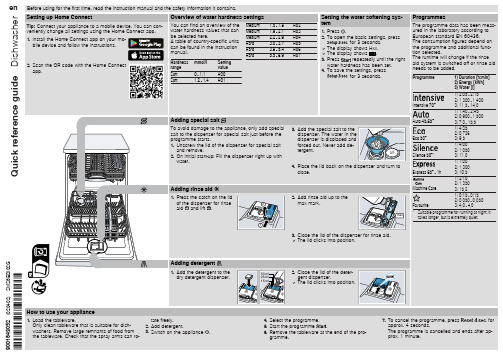
washers. Remove large remnants of food from 3. Switch on the appliance .
the tableware. Check that the spray arms can ro-
4. Select the programme. 5. Start the programme . 6. Remove the tableware at the end of the pro-
gramme.
7. To cancel the programme, press
for
approx. 4 seconds.
The programme is cancelled and ends after ap-
prox. 1 minute.
Cleaning filters
1. After each wash check the filters for
Programme
1) Duration [h:min] 2) Energy [kWh] 5 - 2:15 2) 1,300 - 1,400 3) 11,5 - 14,0
Auto 45-65°
1) 1:40 - 2:45 2) 0,900 - 1,500 3) 7,0 - 15,5
Adding detergent
1. Add the detergent to the dry detergent dispenser.
50 ml
2. Close the lid of the deter-
25 ml
gent dispenser.
15 ml
a The lid clicks into position.
D-LINK DVCAM-Z视频管理平台安装及使用说明书V2.1

软件安装点击“下一步”完成配置。
安全权限的配置:打开“控制面板”中的“管理工具”中的“Internet 信息服务”Web 服务扩展”,将“所有未知CGI扩展”“所有未知ISAPI扩展”设置为允许。
如用户管理主界面的左上部分是显示当前系统的用户列表。
您可以通过点击列表右侧的“用户管理”来修改已存在用户的属性,如显示名、密码、添加显示组设置完所有的视频设备后,接下来就对镜头进行分组了。
显示组是用于在DVCAM 览器端将摄像头按组分列方便浏览。
先选定一个用户,然后再分组信息栏中右键显示弹出菜单,选择“添加显示组”点击后会弹出“分组属性”对话框。
如下图:您也可以在“分组信息”栏里点击选择摄像头以后,点击“移出分组”来删除已添加的摄像头。
软件可以对从硬件服务器发送出来的格式为“AXIS+空格+数字”的TCP Message面板中的来设置报警触发录像的您可以通过点击来对设置进行修改。
面板中的点击“确定”完成设置。
同时在DVCAM浏览器端弹出报警实时画面提示工作人员。
如下图:从录像服务器“录像列表”及DVCAM浏览器“录像资料查询”中可以查看报警录像。
电子地图电子地图可以很方便的让您了解到各个视频采集器的工作状态,可以使安防人员快速发现报警设备以减少反应时间。
电子地图支持触摸屏操作。
在电子地图中,您可以在监控区域的模拟图中添加设备,您可以随时双击任一个设备进入此设备的实时画面。
当有设备侦测到报警情况时,对应摄像头图标会产生闪烁,可以在第一时间在电子地图上了解到具体报警的设备的位置。
下面我们来做一个简单的电子地图:首先,点击“电子地图”弹出电子地图对话框。
如下图:点击地图栏里的添加按钮,在弹出的对话框添加地图名并在“地图地址”选项中点击“选取”,通过浏览找到做主地图的JPG格式图片。
如下图:点击“确定”后,主地图添加成功。
然后可以点击地图栏里的“添加”来添加或使用热区功能来添加第二层地图。
下面使用热区的例子演示。
迪乐克 DCS-7110 全高清室外昼夜网络摄像机 使用说明书

HD Outdoor Day & Night IP CameraDCS-7110Key Features• 1/4” megapixel progressive CMOS sensor• HD resolution: 1280 x 800 (megapixel) at 30 fps• IP-66 certi ed weatherproof housing• PoE powered – no need for a separate power supply• Built-in IR LEDs for Day & Night operation(15 m. illumination distance)• Built-in IR-Cut Removable (ICR) lter, for enhanced colourrendering in the day and good results in low light conditions• Simultaneous streaming in H.264, MJPEG and MPEG-4compression• Hardware-based motion detection• Tamper detection• IPv6 support• Privacy mask function• 3GPP support – watch live video from a compatible smartphone• Digital I/O support for sensors and alarms• Open Network Video Interface Forum (ONVIF) compliant• D-ViewCam TM (DCS-100) monitoring software included(support for up to 32 cameras)The D-L ink DCS-7110 is a high-de nition outdoor IP Camera, equipped with a1/4” megapixel CMOS sensor and 4 mm F1.5 xed-focus lens. The DCS-7110 is capableof capturing videos in both dark and light environments with its built-in IR L EDs andremovable IR-cut (ICR) lter, which provides high quality videos day or night. The ICR ltercan be manually applied via the web or set to automatically adjust based on lightningconditions. Capture crisp color images during the daytime and detailed greyscale imagesat night or in or low-light conditions.Multiple Video StreamsThe DCS-7110 supports simultaneous streaming of H.264, MPEG-4, and MJPEGvideo to provide both high-quality and bandwidth-e cient compression formats.MJPEG delivers excellent le integrity, ideal for situations which require extensive imagedetail. H.264 produces a small le size, making it more useful for extended recording orfor use in low-bandwidth networks. Additionally, the DCS-7110 supports multicast H.264streaming, allowing users to view the camera images by subscribing to a multicast groupon the network.Flexible ConnectivityThe DCS-7110 includes input and output ports for connectivity to external devices suchas IR sensors, switches, and alarm relays. It also comes with an RS-485 interface, providingconnectivity to an optional pan/tilt enclosure. The DCS-7110 also incorporates Powerover Ethernet (PoE), allowing it to be easily installed in a variety of locations without theneed for supplemental power cabling.Tamper DetectionDesigned to be mounted outdoors, the DCS-7110 includes an IP66 certi ed enclosure which protects against the environmental elements. This makes it suitable for tamper-prone locations such as transportation hubs, schools,or correctional facilities. The tamper detection feature can sense whenever the camera has been redirected, de-focused, blocked or spray-painted and respond promptly with a visible or audible alarm.Removable IR-Cut FilterThe DCS-7110 comes with a ICR Filter which can be manually applied via a web interface or can be set to automatically adjust based on lighting conditions. This feature allows the camera to capture crisp colour images during the daytime and greyscale images at night.Open Network Video Interface Forum(ONVIF) compliantThe Open Network Video Interface Forum (ONVIF) is standards relating to open IP video networking. The DCS-7110 is ONVIF compliant and therefore interoperable with other manufacturer’s products on the same network such as cameras, storage systems, video analytics products and Video Management Systems. Centralised management with D-ViewCam™The included D-L ink D-ViewCam™ IP camera surveillance software is a comprehensive surveillance system designed to centrally manage multiple IP cameras. Supporting up to 32 IP cameras, D-ViewCam™ is compatible with all current D-L ink IP cameras, Video Servers and o ers digital monitoring and recording capabilities of video, audio, and events for various security applications. This software provides users with a wide array of features for added convenience, including video recording, playback, video live view, o ering users powerful surveillance software that’s easy to use. If the worst should happen to your network you need the very best support and fast. Downtime costs your business money. D-L ink Assist maximises your uptime by solving technical problems quickly and e ectively. Our highly trained technicians are on standby around the clock, ensuring that award-winning support is only a phone call away.With a choice of three a ordable service o erings covering all D-Link business products, you can select the package that suits you best:D-Link Assist Gold - for comprehensive 24-hour supportD-Link Assist Gold is perfect for mission-critical environments where maximum uptime is a high priority. It guarantees four hour around-the-clock response. Cover applies 24/7 for every day of the year including holidays.D-Link Assist Silver - for prompt same-day assistanceD-Link Assist Silver is designed for ‘high availability’businesses that require rapid response within regular working hours. It provides a four hour response service Monday to Friday from 8am to 5pm, excluding holidays.D-Link Assist Bronze - for guaranteed response on the next business dayD-Link Assist Bronze is a highly cost-e ective support solution for less critical environments. Response is guaranteed within eight business hours Monday to Friday from 8am to 5pm, excluding holidays.D-L ink Assist can be purchased together with any D-L ink business product. So whether you’re buying switching, wireless, storage, security or IP Surveillance equipment from D-Link, your peace of mind is guaranteed. D-Link Assist also o ers installation and con guration services to get your new hardware working quickly and correctly.Technical Speci cationsVideo Algorithms Supported• H.264/MPEG4/MJPEG format compression simultaneously• JPEG for still image• H.264/MPEG-4 multicast streamingHardware Profile• Sensor: 1/4” megapixel progressive CMOS sensor• SDRAM: 256 Mbytes• Flash Memory: 128 Mbytes• ICR: Built-in Infrared-Cut filter Removable module • Lens: 4 mm fixed lens , F1.5• View Angle: Horizontal 65.4 degrees• IR LED: 15 meter illumination distance and light sensorImage Features• Adjustable image size, quality, and bit rate• Time stamp and text overlays• 3 configurable motion detection windows • 5 configurable privacy masks• Flip & mirror• Configurable brightness, saturation, contrast, sharpnessNumber of Ports• 176x144 @ 30 fps• 320x240 @ 30 fps• 640x480 @ 30 fps • 1280x720 @ 30 fps • 1280x800 @ 30 fpsNetwork Protocols• IPv4, IPv6• TCP/IP, UDP, ICMP• DHCP Client• NTP Client (D-Link)• DNS Client, DDNS Client (D-Link)• SMTP Client• FTP Client• HTTP / HTTPS• Samba Client• PPPoE• UPnP Port Forwarding • RTP / RTSP/ RTCP • IP filtering• 3GPP• LLTD• CoS/QoS• SNMP/IGMP • SNMP• IGMP• 802.1x• ONVIF Complian3GPP Mobile Surveillance• Packet Video Player 3.0• QuickTime 6.5• Real Player 10.5 System Requirements for Viewing• Internet Explorer 6 or laterD-ViewCam™ System Requirements• Operating System: Microsoft Windows®7 / Vista / XP • Web Browser: Internet Explorer 6 or higher • Protocol: Standard TCP/IPPower Input• 12 VDC 1.25 A, 240 VAC 50/60 Hz• PoE: IEEE 802.3af Maximum Power Consumption• 6 WOperating Temperature• -20 to 50 ˚C (-4 to 122 ˚F)Storage Temperature• -20 to 70 ˚C (-4 to 158 ˚F)Humidity• 783 gCertifications• CE (Class A)• CE LVD (EN60965-1)• FCC (Class A)• ICES-003, ICES-006• C-TickCamera DimensionsFor more information: D-Link European Headquarters. D-Link (Europe) Ltd., D-Link House, Abbey Road, Park Royal, London, NW10 7BX.Speci cations are subject to change without notice. D-Link is a registered trademark of D-Link Corporation and its overseas subsidiaries.All other trademarks belong to their respective owners. ©2012 D-Link Corporation. All rights reserved. E&OE.Updated 28/01/2013。
视频监控软件(迪威乐)操作手册

目录1基本操作 (1)1.1用户登录 (1)1.2工具栏介绍 (2)1.3本地配置 (3)1.4修改密码 (4)2设备配置 (5)2.1配置分支 (5)2.2配置主机 (5)2.3配置通道 (7)2.4配置服务 (8)3实播 (11)4回放 (15)4.1录像回放 (15)4.2图片回放 (17)5计划录像 (18)6报警配置 (20)7系统管理 (22)7.1健康管理 (22)7.2告警查询 (22)7.3日志查询 (23)8用户管理 (25)8.1新增用户 (25)8.2修改用户 (26)8.3删除用户 (26)8.4修改权限 (26)1基本操作双击桌面服务器图标或确保服务器程序正在运行。
1.1用户登录双击客户端图标后出现登录界面,如图1.1:图1.1登录界面用户首次登陆客户端,需填写用户名为super,密码为123456。
选择“记住密码”,下次登陆时不用再次输入密码。
点击“网络设置”,弹出登录模式选项。
本地登录模式:启动本地服务,客户端将会连接本地数据库,纯单机化运行。
远程登录模式:客户端将会远程连接其他电脑的数据库,填写所要连接电脑的IP地址、服务器端口即可(端口安装时服务器和客户端默认均为18000,如果日后服务器更改端口,客户端登录时则需同步更改)。
此模式真正实现了网络化运行。
外网模式:可在广域网上访问远端服务器。
复选项为选中,或均为未选中,如:,程序中所有如此外观的复选项均遵循。
1.2工具栏介绍1.2.1上侧工具栏上侧工具栏中是系统的几大功能,分别点击不同的按钮,进入各功能界面。
1.2.2右下侧工具栏图1.2右侧工具栏选择云台标签:云台控制区用来控制有云台及可变焦的摄像机,区内提供了,4个方向的转动,通过拖动云台转速调节云台的转动速度,速度级别为0-10,默认为速度为5。
在方向控制圈外环绕着的功能键由上至下依次为调焦距“、”、聚焦“、”、光圈“、”。
“预置点”设置后点击“调用”可快速转移指定摄像机至预设点。
iDVR 3.1使用手册
AVinfo iDVR 3.1 网络视频监控系统安装说明及用户指南(版本号Build66 )北京先进视讯科技有限公司2010年11月修订目录第一章说明 (4)第三章安装说明 (6)3.1安装服务器系统要求 (6)3.2服务器端软件安装 (6)第四章控制面版(ADVController)配置 (10)1. 配置目录服务 (11)2. 配置网关服务 (12)3. 配置转发服务 (13)4. 启动各项服务 (15)第五章管理界面说明 (16)5.1 编码器管理 (16)5.1.1 视频参数设置 (18)5.1.2 音频设置 (20)5.1.2.1 麦克风 (20)5.1.2.2 扬声器 (20)5.1.3报警输入/输出 (21)5.1.4 串口设置 (21)5.1.4.1 串口参数 (21)5.1.4.2 添加PTZ (22)5.2镜头分组 (22)5.2.1 添加设备组 (23)5.2.2 删除设备组 (25)5.3用户管理 (26)5.3.1 建立用户 (27)5.3.2 用户权限的设置 (28)5.3.3 删除用户 (29)5.3.4 添加分组 (30)5.3.5 为用户指定分组 (30)5.3.6 删除分组 (31)5.4录像管理 (31)5.4.1录像文件的管理 (32)5.4.2 选择镜头 (32)5.4.3 计划录像 (33)5.4.6 手动录像 (35)5.4.7 回放录像 (36)5.5报警联动 (36)5.6电子地图 (37)5.6.1 上传地图 (37)5.6.2 为地图分配镜头 (37)5.7日志管理 (38)第六章客户端使用说明 (39)6.1登录监控系统 (39)6.2下载客户端 (41)6.2.1在登录界面直接点击下载客户端 (41)6.2.2 实时监控下自动下载 (46)6.3 客户端界面功能说明 (46)6.3.1摄像机和视频显示区 (47)6.3.2 镜头云台控制区 (49)6.3.3 录像查询 (51)6.3.4 辅助设备控制 (54)6.3.5本地实时录像 (54)第一章说明AVINFO iDVR Ver3.1是北京先进视讯科技有限公司开发的专业的网络视频监控管理系统,基于目前最流行的Browser / Server构架,可以通过任何IP网络(Unicast / Multicast)进行数字视频/音频的传输和管理;同时提供基于Client / Server构架的网络视频监控管理系统。
DVR快速入门指南
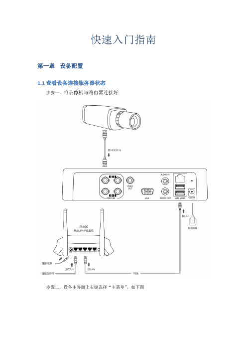
快速入门指南第一章设备配置1.1查看设备连接服务器状态步骤一,将录像机与路由器连接好步骤二,设备主界面上右键选择“主菜单”,如下图步骤三,在点击主菜单后弹出的画面为输入密码框图,请输入DVR的登录密码,默认用户名:admin密码:123456如下图步骤四,输入密码后进入主菜单,点击配置管理,如下图步骤五,点击配置管理后,再点击网络配置,如下图步骤六,点击网络配置后,再点击穿网服务,如下图步骤七,点击穿网服务后显示,如下图步骤八,点击穿网服务后,先开启穿网功能,点击【确定】就完成设备配置了。
“穿网功能”:开启和关闭(扫描机器自带的二维码一键添加设备)“设备ID”:每台设备的唯一序列号,不可修改。
“控制密码”:设备自动生成,可以修改。
“本地端口”:默认为3000,可以修改。
“连接状态”:查看设备与服务器连接状态:①已连接②无法连接到Internet。
①已连接,正常。
②无法连接到Internet,异常。
当发现异常时,可以点击【Ping】查看当前设备与Internet连接情况。
注意:连接状态显示无法连接Internet,请检查网口灯是否亮着,设备是否能连上Internet 网。
第二章P2P网络操作2.1控件安装在浏览器地址栏中输入P2P网站服务器地址(Web服务所在PC的IP地址,如),进入登录页面。
如下图:自动弹出internet Explorer –安全警告提示框,如下图:点击【运行加载项】,弹出加载ActiveX控件对话框,如下图:控件无法下载,IE的安全级别较高,点击【确定】后调整IE设置即可步骤1,点击【工具】,选择Internet选项,如下图:步骤二,选择可信站点,点击【站点】,如下图:步骤3,点击【添加】,添加成功后,点击【关闭】,如下图:步骤4,选择可信任站点,点击【自定义级别】,如下图:步骤5,开启所有ActiveX控件提示、下载和运行,点击【确定】,如下图:步骤6,再次刷新网站,点击【安装】,如下图:表示已经完成控件安装,可以正常使用。
LUM-500-DVR系列DVR监控录像机快速使用指南说明书

LUM-500-DVR Series DVR Surveillance Recorder Web Interface Quick StartGuide2DVR Quick Start GuideFor maximum control and convenience, your system should be connected to the Internet via a local network router. For installation, you must be able to access this network through a personal computer.Internet connectivity allows you to use OvrC, a powerful remote maintenance service. See for details. If your surveillance system is isolated from the Internet, go to and download the technical reference manual for this product, which has a chapter that steps you through installation without using the web interface.Required Equipment}The DVR and all cameras to be installed}Network connection for the DVR}Admin rights to a network computer that can access the surveillance system}Phillips screwdriver}T wo AAA batteries for the remote controlAdditional ResourcesYou can acquire a PDF of the full DVR technical reference manual, hard drive installation guide, and other materials from the product page at .If you are going to install extra hard drives in the recorder, do so now before beginning installation.3DVR Quick Start GuideSafety Tips}Handle this device with care. }Do not strike or shake this device.}Do not operate this device beyond its specified power source ratings.}Protect the power cord from being stepped on or pinched, particularly where it connects to the device and to the power outlet.}Do not drop items through the ventilation slots. If something falls inside the device, turn off the power immediately and contact qualified personnel for service.}Do not expose this device to water or moisture. Moisture may damage the device and cause electric shock.}T ake immediate action if the device becomes wet: turn the power off and contact qualified personnel for service.}Do not use this device in humidity above 85%.}Do not use this device near any heat sources such as radiators, heat registers, stoves, or other such heat-generating equipment.}If mounting in a closed space, include adequate ventilation. Do not block ventilation openings.}The performance and lifespan of the hard driveis affected by temperature. Use this device in temperatures ranging from 14–131 °F . }Handle the hard drive with care.}You can damage the hard drive if this device is moved while the hard drive is still spinning. If you must move the device, even just to reposition it, follow the shutdown procedure in the technical reference manual (available online) and wait at least 30 seconds before moving it.}If servicing or exchanging the hard drive, protect it from static electricity. Use a grounded static wrist guard and mat to properly ground yourself and the hard drive.}Do not use an electric screwdriver to remove or install a hard drive.}Clean this device with a dry cloth. Do not use strong or abrasive detergents when cleaning the device chassis. If dirt is hard to remove, use a mild detergent and wipe gently.}Make a note of the system settings and save them. This helps when changing the system configuration or with recovery if unexpected failure or trouble occurs.4DVR Quick Start GuideBox ContentsThe following materials are included in your package:}This quick-start guide}The Luma DVR}Extra screws for mounting an additional internal hard drive into your DVR (-8CH and -16CH only)}SATA cables for connecting an additional internal hard drive in your DVR (-8CH and -16CH only)}Rack ears for installing your DVR into a rack}Screws for attaching the rack ears to the DVR}USB mouse}Remote control}Power cord}Stick-on rubber feet for the unit if you will not be installing it in a rackPlease note that distributing, copying, disassembling, reverse compiling, reverse engineering, or exporting the software provided for this product is expressly prohibited and in violation of international copyright law.5DVR Quick Start GuideSet Up the HardwareCaution: Do not power up the DVR until these steps are complete.1. If desired, install the DVR in the rack. If not, attach the rubber feet to the bottom corners of the unit.2. Connect the mouse to the USB port on the rear panel. We suggest that you leave the front USB unused andaccessible for later use.3. If desired, connect a local monitor to the VGA , HDMI , or video out port.4. Connect your analog surveillance cameras to the video in ports. Ensure that the cameras have power. IP cameras cannot be used with this system.5. Connect your network cable to the Ethernet port.6. Connect the power cord and turn on the power switch.Camera(s)6DVR Quick Start GuideInstall the Luma UtilityUse the Luma Utility to locate your surveillance hardware and set up communications.Download and Install the Luma UtilityVisit your product page at SnapAV .com and download the Luma Utility installer.Once it has downloaded, double-click on the Luma Utility icon to run the installer. You can click through and accept the defaults.Locate the DVRRun the Luma Utility.It searches the local network for all Luma Surveillance devices. If your DVR does not appear, ensure that the network connections are secure and that the unit is powered up, then clickthebutton. Click on the entry for your DVR to view its details. Double-clicking on the DVR opens its webinterface.7DVR Quick Start GuideEdit the Network SettingsIf you need to change the network settings at a later date, consult the manual.Set the IP AddressAt the top of the right column of the Luma Utility, make a note of the IP address. You will need this in the next step.Deselect the Enable DHCP box to make the IP address static.Change the Server, HTTP , and RTSP PortsThe H TTP port defaults to 80. This port enables you to access your recorder through a web browser.The server port defaults to 8000. This port enables the Luma mobile application to access your system.The RTSP port defaults to 554. This port enables the Luma mobile application to access your system’s live view.For security reasons, we suggest you change your ports and make a note of the new port numbers for your records. Consult your server or router manual for common and reserved port numbers to avoid.T o confirm changes, enter the password admin and then click Save.8DVR Quick Start GuideStart the Web InterfaceGet the Luma Plug-InOpen your browser, type the IP address of the recorder (from page 7) into the address bar, and hit Return . Below the login window, there may be a link that reads, “Please click here to download and install the plug-in. Close the browser when installing the plug-in.” If so, download the plug-in and close all instances of your browser, including any running in the background.Install the LumaWebComponents plug-in.Restart your browser and return to your recorder’s login window. Enter admin for both the user name and password.You might get a pop-up message* that asks you whether you want to run the Luma Web Components plug-in. You must allow the plug-in to access your system. * Google Chrome does not have a pop-up message. Instead, look in the right end of the address bar for an icon of a puzzle piece with an X over it, as shown in the image to the right. Click on this to enable the plug-in.Be sure to save your recorder’s page as a favorite in your browser.9DVR Quick Start GuideCheck the CamerasAfter log-in, your screen shows the live page, which should look similar to the illustration at right. If not, check the connections on your cameras and DVR, and ensure each camera is powered up.Adjust Camera SettingsFor cameras that have on-screen menu options to adjust their settings, you can control those menus through the DVR interface.T o adjust H D-TVI cameras, click the PTZ control icon ( ), then press the menu icon ( ) in the configuration bar. Reference the manual for detailsand the proper protocol.10DVR Quick Start GuideSet Up Dynamic DNSThis allows you to connect to your surveillance system from anywhere, via the Internet, using a web address that’s easy to remember.Click on Remote Configuration > Network Settings > DDNS.Click the box labeled Enable DDNS, then choose a type from the DDNS T ype menu. Next, choose a server address. We recommend WirepathDDNS and .Enter your desired domain in the Domain box. This creates a personalized server address, which is shown under Device URL.If someone has already registered your desired domain, the system adds a unique ID (typically two to four digits) to your domain. If you do not like these digits, try another domain or server address.Example: If you choose the domain myhome(as shown), your system’s URL would be. If someone alreadyhad myhome, then your system’s URL wouldbe something li e myhome13.LumaDNS.com.Click Saveto finalize the settings here.11DVR Quick Start GuideSet Up Port ForwardingPort forwarding is typically found under the Applications & Gaming section of your router.T o complete port forwarding, you will need:}the IP address of the DVR (found under Remote Configuration > Network Settings > TCP/IP , in the boxlabeled IPv4 Address), and}the server, HTTP , and RTSP port addresses, which you set on page 7.Refer to your router’s user manual for full details.Once you’ve finished, your device’s URL (e.g., ) gets you to the login page of your DVR, no matter where you are. If you changed your HTTP port from the default location (80), add a colon and the new port number to the URL (e.g., MyHome.LumaDNS:8042).12DVR Quick Start GuideCreate Users and Set PasswordsClick on Remote Configuration > User Management.Change the Admin PasswordClick on the admin account, then click Modify.Passwords cannot be longer than 16 characters. T o ensure compatibility with the localinterface, passwords can only contain numbers, letters, spaces, and the followingspecial characters: . , : - /Use a password that is long and easy to remember. A password like parisinthespring ismore secure and easier to remember than a password like P4S$w*rD.Add Additional UsersClick the Add button. Enter the new account’s user name and password. Accountnames can be up to 32 characters long, and can contain numbers and letters only.We recommend that you add accounts by individual users’ names, so that if someonereboots the system or erases a log, you know which user did it.Choose the account’s level. There are two levels for users: operator and user. The onlydifference is the default permissions they are given. You can customize permissionsfor each account individually. See the technical reference manual (available online)for more details.13DVR Quick Start GuideCalibrate the System TimeClick on Remote Configuration > Device Parameters > Time Settings .Synchronize the TimeChoose your time zone. North American time zones range from GMT-10:00 (Hawaii)to GMT-03:30 (Newfoundland).By default, the system uses network time protocol (NTP) to synchronize your systemto Coordinated Universal Time. We strongly recommend using NTP to keep yoursystem well calibrated.If you want to use manual time sync, or if your system is isolated from the Internet,see the technical reference manual (available online).Disable DST if NecessaryIf you are in a location that does not observe daylight saving time, click the EnableDST checkbox to deselect it.Click Saveto confirm changes.14DVR Quick Start GuideYou’re Done! Your system is now operational.Next StepsNext, you’ll want to customize your system for your customer’s needs. Using the simple web interface, you can:}Set protocols for remote computers for when they log in to the surveillance system.}Change the cameras’ frame rates to manage hard disk space.}Set a custom recording schedule.}Arrange for the system to send alert emails when an alarm is triggered.}Create privacy masks.}Set up alarms to trigger from the camera, and vice versa.… and more!T o learn more about these capabilities, go to the product page at and download the technical reference manual.15DVR Quick Start GuideSupportNeed Help? Contact Tech Support!If you need further clarification, please email support@SnapAV .com. For more information, instructional videos, support documentation, or ideas, visit our website and view your item’s product page at SnapAV .com.3-Year Limited WarrantyThis Luma Surveillance™ product has a 3-Y ear Limited Warranty. This warranty includes parts and labor repairs on all components found to be defective in material or workmanship under normal conditions of use. This warranty shall not apply to products that have been abused, modified or disassembled. Products to be repaired under this warranty must be returned to SnapAV or a designated service center with prior notification and an assigned return authorization (RA) number.Copyright ©2015 by SnapAV . All rights reserved. SnapAV , Luma Surveillance, Wirepath Surveillance, and all related marks and images are trademarks or registered trademarks of SnapAV .Version 150817-1120.。
D-ViewCam VE4.0监控系统软件说明书1.0

D-ViewCam VE4.0操作手册目录1.设备管理 (2)1.1 客户端电脑配置要求 (2)1.2添加设备 (2)1.3删除设备 (3)2.客户端操作界面说明 (5)2.1 客户端登录与退出 (5)2.2 客户端主控界面介绍 (8)3.图像操作 (19)3.1 图像显示、抓拍及删除 (19)3.2 镜头/设备参数设置 (20)3.3 PTZ控制设置 (25)3.4 电子地图 (25)3.5 虚拟镜头 (29)3.6 布局 (33)3.7 图像的轮巡 (34)3.8 图像上电视墙 (39)4.录像计划查询及回放 (41)4.1 录像设置 (41)4.2 录像查询 (45)4.3 录像回放 (48)5.报警设置 (57)5.1报警计划设置 (57)5.2 移动帧测 (67)6.用户设置 (70)6.1 用户管理 (70)7 日志查询 (76)7.1用户信息 (77)7.2设备状态 (78)7.3报警信息 (78)7.4子服务器信息 (79)7.5刷卡信息 (80)8.系统应用 (82)8.1 音视频调度会议 (82)8.2 系统集成 (85)8.3 图像增强 (87)8.4 即时通信与桌面共享 (89)附录客户端备份工具的使用 (92)1.设备管理1.1 客户端电脑配置要求1.2添加设备1.2.1添加网络摄像机将网络摄像机和客户端电脑联网,打开Configurator配置工具软件,如果网络摄像机和客户端都在同一局域网内,Configurator会自动发现该设备。
并在左侧列表区内显示出网络摄像机的网络参数,如下图所示:发现IP地址后,可以根据摄像机所在的网络环境及用户的实际要求,更改设备的网络参数,包括设备的IP、网关、字码掩码、指向服务器等。
“指向服务器”项即填写系统服务器的IP地址设置好后点击“提交”按钮,完成设置此时通过客户端访问管理服务器时即可在界面左侧的服务器镜头列表区显示出该设备。
1.3删除设备如果想把一个设备从设备列表中删除,可以按以下操作步骤进行操作:1、让设备断电或断网170秒(时间可在服务器配置工具中更改)以上,客户端镜头/设备列表中该设备的图标上出现红叉(找不到该设备)。
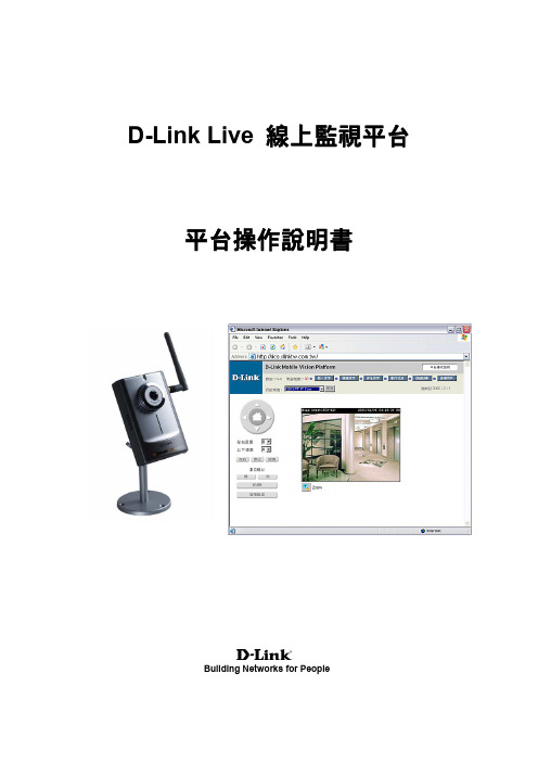
D-Link Live 線上監視平台 操作说明书
3.頻道觀看............................................................................................................................................. 13
二. 相容產品
D-Link Live 需搭配以下設備: z DCS-2120:網路攝影機 (需有 D-Link 相容認證) z 行動保鏢:安防設備 (無線磁簧、紅外線、瓦斯偵測、煙霧偵測...等)
2
三.網站操作說明
1.開始使用
拿出您的「D-Link」帳號卡: ID:為您的登入帳號 PWD:為您的登入密碼
以在保全應用做一個強大的監視系統。 DCS-2120 可以與任何有線及無線的 802.11g 路由器 使用。 本章節將說明如何從網際網路及在內部網路觀看攝影機。 需要設備: ¾ 1 台 DCS-2120 網路攝影機 ¾ 1條乙太網路線 ¾ 1 台有線或是無線的路由器,如 D-Link DI-624S 無線路由器 ¾ 具備網路連線功能的個人電腦方便做系統設定
D-Link Live ᇞɪ္ൖ̨̻
̨̻ЪႭࣣ
Building Networks for People
目錄 一. 簡介特色..................................................................................................................2 二. 相容產品..................................................................................................................2
威迪PROG用户手册.pdf_1699991568.9772215说明书

CONTENT1. Document Declaration (3)2. Safety Precautions (4)3. Noun explanation (5)4. Hardware Overview (6)4.1. Device specification (6)4.2. Device units (7)4.3. Unit description (11)5. Software Overview (15)5.1. Introduction (15)5.2. Software interface (16)5.3. Driver installing (18)5.4. Online update (19)6. Support Type List (20)6.1. MEMORY (20)6.2. MCU (22)7. Support Model List (61)7.1. ECU (61)7.2. IMMOBILIZER (63)7.3. DASHBOARD (67)7.4. REMOTE (72)7.5. AIRBAG (73)7.6. OTHER (75)1.D ocument DeclarationPlease view the following declaration carefully:◆VVDI PROG User Manual can help you maintenance vehicles with device.Please DON’T used for illegal purpose, Please follow the national laws ◆VVDI PROG User Manual can help you how to use VVDI PROG software,please view carefully◆Any illegal use VVDI PROG Device or User Manual,The user should takeall risks, the company does not assume any responsibility◆This User Manual according to V4.8.9,new version software please refer tocorresponding version User Manual2.S afety PrecautionsTo prevent personal injury or device damage, please read the User Manual carefully before operation and adopt the following safety precautions:◆Always operate the device under safe condition◆Ensure work condition with good ventilation, because of the harmful gasgenerated when soldering◆Soldering on anti-static & constant temperature solder station◆Disconnect power supply before soldering◆Ensure solder station connected to ground◆Keep the device clean and dry, Do not place in any wet, oily, dusty area3.N oun explanation◆EEPROM: Electrically Erasable Programmable Read-Only Memory,usually store the generated data of chip running◆FLASH: Flash EEPROM Memory, usually store the program of chip◆D-FLASH: Data Flash, the same function with EEPROM◆P-FLASH: Program Flash, the same function with FLASH◆ROM: Read-Only Memory, usually store the program of chip, can noterase or write◆EEE: Emulated EEPROM, the same function with FLASH◆POF: Program Once Field, can write data once, can not erase or rewrite4.H ardware Overview4.1.Device specification4.2.Device units1. VVDI PROGdevice2. EEPROM socket3. EEPROM adapter4. MC9S12 Reflash Cable V15. MCU Reflash Cable V36. ECU Reflash Cable7. USB Type-B Cable8. TB28FXXX adapter (optional)9. PCF79XX adapter (optional)10. M35080/D80 adapter (optional)11. EWS3 adapter (optional)12. EEPROM CLIP adapter (optional)13. EWS4 adapter (optional)14. TMS370 adapter (optional)15. AM29FXXX adapter1(optional)16. AM29FXXX adapter3 (optional)17. AM29FXXX adapter4 (optional)18. AM29FXXX adapter2 (optional)19. MC68HC05BX adapter (optional)20. MC68HC05X32 adapter (optional)21. SPRINTER(ST12) adapter (optional)22. W164(ST12) adapter (optional)23. W169(ST12) adapter (optional)24. W209/211 ZGW adapter (optional)25. W639(HC08) adapter (optional)26. VITO W639(ST12) adapter (optional)27. W203(HC08) adapter (optional)28. W209/211(HC12) adapter (optional)29. W211(ST12) adapter (optional)30. W215/W220/W230 adapter (optional)Unit description1.16 Pin DIP socketFunction: Read EEPROM chipsUse method: Follow the image direction when insert the DIP chip (PIN1 as yellow point show as the picture); SOP chip need soldering on 16Pin adapter first, then insert the chip follow the image direction2.MC9S12 Reflash Cable V1Function: Read & Write MC9S08, MC9S12 series chips, current version is V1Use method: Soldering the line on pin of chip before read & write Notes:(1) Please check all connection lines,ensure correct and reliable connection(2) Please Don’t lengthen CLK and GND-C line, maybe cause read data failed3.MCU Reflash Cable V3Function: Read & Write MC68HC(9)12, V850, H8X, R5C series chips, current version is V3Use method: Soldering the line on pin of chip before read & write Notes:(1) Please check all connection lines,ensure correct and reliablec onnection(2) Please Don’t lengthen CLK and GND-C line, maybe cause read data failed4.ECU Reflash CableFunction: Read & Write engine ECUUse method: Connect the ECU and R&WNotes:Please check all connection lines, ensure correct and reliable connection5.S oftware Overview5.1.Introduction◆Support R&W lots of chips, include MC9S08 series, MC68HC(9)12series,MC9S12series, V850series, H8Xseries, R8Cseries, PCF79XXseries and most eeprom chips etc .◆Support chip data verify, checkblank function◆Support data file compare function◆Support R&W BMW N20, N55 ECU(show ISN directly)◆Stable R&W MC9S12XE series chips(5M48H/1N35H/2M53J/3M25J etc.)◆Support renew PCF79XX remote, currently support BMW E/F series◆Lots of connection diagram5.2.Software interface1. Operation optionsFile : Load data fileBuffer : Support copy, paste, search, fill functionDevice : Support chip read, write, erase operationWindow : Compare two data filesSetting : Read&Verify, Write&Verify, Erase&Check Blank configuration Language : Change the language, current support English, Chinese,Polish, Arabic, Czech, Spanish, French, Italian, Portuguese, Russian,Turkish2. General optionsProvide General function buttons, simple and easy for operation, include: new, open, save, read, write, verify, check blank,erase,calculator &upgrade3. Read rangeParts of chips include several data areas, for example EEPROM, FLASH and etc. click on the button select read range4. Data displayDisplay the read data or load data, include hex and ASCII format5. Power configurationDisplay the status of power ( VCC, VPP, 12V), support change the voltage of VCC and VPP (The default voltage usually not need to change)6. Special function optionsProvide chips special function, for example parts of chips have read chip ID, set security, reset security etc .7. Chip optionSelect right option according to type,brand and chip8. Option InformationDisplay parameter information of current option9. Connection diagram buttonClick on button, get the connection diagram of current chip10. adapter TypeDisplay needed adapter of current option11. Operation InformationDisplay operation information and saved in “log.bin” file5.3.Driver installingThe driver install software saved in “driver” folder, include 2009 and 2016 version (recommend select 2009 version)5.4.Online update◆This function require internet support◆Click the “Upgrade” button enter the upgrade interface, show as followingpicture◆Enter update interface,if software show”communication with serverfailed”,please close your Anti-virus and computer firewall and retry.Ifsoftware show“unable to find equipment”,please reconnect device◆Tip information show the latest software version and upgrade information ◆Device information show the device SN, device firmware version and thelatest firmware version◆Firmware upgrade steps:1. Select the firmware version2. Click “Start Firmware Upgrade” button3. Don’t close or pull out USB cable before upgrade finished◆Software upgrade steps:1. Click “Software Link 1” or “Software Link 2” button, download softwarefrom the web2. Extract the file6.S upport Type List6.1.MEMORY6.2.MCUNotes: Already Support, Support SoonNotes: Already Support, Support SoonNotes: Already Support, Support SoonNotes: Already Support, Support SoonNotes: Already Support, Support SoonNotes: Already Support, Support SoonNotes: Already Support, Support SoonNotes: Already Support, Support SoonNotes: Already Support, Support SoonNotes: Already Support, Support SoonNotes: Already Support, Support SoonNotes: Already Support, Support SoonNotes: Already Support, Support SoonNotes: Already Support, Support SoonNotes: Already Support, Support Soon。
迪威乐w888说明书

迪威乐w888说明书
一、智能锁输入密码
操作步骤:1.打开电池盖。
2.按设置键一次响滴声。
3.按启动键(位于键盘数字3后面一位),输入密码(3-8位)按#键。
4.响起滴声,操作成功。
二、密码和指纹设置
操作步骤:1、打开电池盖。
2.按设置键一次。
3.按启动键,输入密码(3-8位)按#键。
4.按启动键,输入编号(00-99)按#键。
5.按启动键,输入开门(3-8位),按#号键结束,密码设置成功;将手指对准指纹窗口读取指纹,滴声响后,再次将同一手指按住读取指纹。
两次读取响声相同,表示指纹录入成功。
三、删除密码和指纹设置
1、打开电池盖。
2.连续按设置键两次。
3.按启动键,输入管理者密码,按#键。
4.按启动键,输入要删除的指纹、密码、遥控器对应编号、按#号键。
FPVDVR说明书2
电气特性..............................................................................................................4
简介:
FPV264,针对航模使用,特点有:低功耗,宽电压工作,断电录像不丢 失,无缝录像。
视频设定:
按 MENU 键进入菜单设置:
按键说明:
REC:录像键,开始/停止录像。 MODE: 模式键,进入/退出回放模式。 MENU:菜单键,进入/退出菜单设定。 UP:上键,上一个选项。 DOWN:下键,下一个选项。
运动检测 打开后,检测到运动物体,会自动进行录像。
运动检测灵敏度 可以根据实际使用情况调节。
日期标签 可以将日期时间叠加到录像中,也可以不叠加。
录像音频 可以将音频录到文件中,也可以不录。
影像质量 图像质量越高,图像越清晰,文件也会越大。
高级设置
连按两下菜单键,即可进入高级设定选项。
语言设置 8 国语言提供选择。
分辨率.................................................................................................................1 循环录影.............................................................................................................1 运动检测.............................................................................................................1 运动检测灵敏度................................................................................................ 2 日期标签.............................................................................................................2 录像音频.............................................................................................................2 影像质量.............................................................................................................2 高级设置.....................................................................................................................3 格式化.................................................................................................................3 日期/时间...........................................................................................................3 语言设置.............................................................................................................3 TV 模式............................ ................................................................................ 3
- 1、下载文档前请自行甄别文档内容的完整性,平台不提供额外的编辑、内容补充、找答案等附加服务。
- 2、"仅部分预览"的文档,不可在线预览部分如存在完整性等问题,可反馈申请退款(可完整预览的文档不适用该条件!)。
- 3、如文档侵犯您的权益,请联系客服反馈,我们会尽快为您处理(人工客服工作时间:9:00-18:30)。
目录1基本操作 (1)1.1用户登录 (1)1.2工具栏介绍 (2)1.3本地配置 (3)1.4修改密码 (4)2设备配置 (5)2.1配置分支 (5)2.2配置主机 (5)2.3配置通道 (7)2.4配置服务 (8)3实播 (11)4回放 (15)4.1录像回放 (15)4.2图片回放 (17)5计划录像 (18)6报警配置 (20)7系统管理 (22)7.1健康管理 (22)7.2告警查询 (22)7.3日志查询 (23)8用户管理 (25)8.1新增用户 (25)8.2修改用户 (26)8.3删除用户 (26)8.4修改权限 (26)1基本操作双击桌面服务器图标或确保服务器程序正在运行。
1.1用户登录双击客户端图标后出现登录界面,如图1.1:图1.1登录界面用户首次登陆客户端,需填写用户名为super,密码为123456。
选择“记住密码”,下次登陆时不用再次输入密码。
点击“网络设置”,弹出登录模式选项。
本地登录模式:启动本地服务,客户端将会连接本地数据库,纯单机化运行。
远程登录模式:客户端将会远程连接其他电脑的数据库,填写所要连接电脑的IP地址、服务器端口即可(端口安装时服务器和客户端默认均为18000,如果日后服务器更改端口,客户端登录时则需同步更改)。
此模式真正实现了网络化运行。
外网模式:可在广域网上访问远端服务器。
复选项为选中,或均为未选中,如:,程序中所有如此外观的复选项均遵循。
1.2工具栏介绍1.2.1上侧工具栏上侧工具栏中是系统的几大功能,分别点击不同的按钮,进入各功能界面。
1.2.2右下侧工具栏图1.2右侧工具栏➢选择云台标签:云台控制区用来控制有云台及可变焦的摄像机,区内提供了,4个方向的转动,通过拖动云台转速调节云台的转动速度,速度级别为0-10,默认为速度为5。
在方向控制圈外环绕着的功能键由上至下依次为调焦距“、”、聚焦“、”、光圈“、”。
“预置点”设置后点击“调用”可快速转移指定摄像机至预设点。
➢选择参数标签:选中要调节的播放窗口,拖动滑动条上的滑块,可设置通道的视频参数,默认值为5。
➢选择巡航标签:选中某一实播通道,巡航路径可以设置该摄像机云台移动路径,调用巡航路径可以控制摄像机按指定路径巡航。
点击“添加巡航点”按钮,在预置点列表中选择需要的预置点。
一条巡航路径可添加多个巡航点。
1.3本地配置界面右上角“菜单”,可进行“本地配置”,弹出窗口如图1.3:图1.3本地配置界面1.3.1常用配置➢启动设置勾选上“开机启动”后即将锐眼视频监控卫士列入您的启动项,电脑启动的同时,一起打开锐眼。
勾选上“程序始终保持在最前面”后锐眼视频监控卫士的主界面将会遮挡住其他软件,处于屏幕的最上方。
➢退出设置可选择“最小化到托盘,不退出程序”,此时程序将被缩小到右下角中,也可以选择“退出程序”。
勾选上“退出程序需要密码验证”后在关闭程序时,需要输入登陆软件时所使用的密码,该设置是为了防止软件被恶意关闭或误操作关闭。
1.3.2实播窗口配置从本地配置>实播窗口配置:初始窗口模式:即选择实播窗口中的多画面切换模式,有一、四。
画面可选择。
默认为四画面。
设备选择区显示模式:即为设备显示列表初始模式,有常规、轮循、场景可选。
默认为常规。
初始显示不在线设备:勾选后将显示不在线的设备,如不勾选则只显示在线的设备。
默认勾选。
自动锁定时间:设置自动锁定时间,当软件在该时段内没有被操作就会被锁定,需要输入登陆时的密码才能进行解锁。
有不锁定、5分钟、10分钟、30分钟可选,默认为10分钟。
锁定时关闭图像:勾选后软件锁定时强制关闭正在播放的图像,默认不勾选。
下次打开软件时自动播放上次退出时正在播放的图像:勾选后下次打开软件时自动播放上次退出时正在播放的图像码流自动切换:设置画面分割数大于预设窗口时,实播的画面会自动切换为子码流播放,初始默认为大于4画面,可选4画面、6画面、8画面和9画面。
1.3.3回放窗口配置从本地配置>回放窗口配置:初始窗口模式:即选择实播窗口中的多画面切换模式,有一、四、六、八、九、十三、十六画面可选择。
默认为四画面。
设备选择区显示模式:即为设备显示列表初始模式,有时间轴、列表可选。
默认为时间轴。
锁定时关闭图像:勾选后软件锁定时强制关闭正在回放的图像,默认不勾选。
1.3.4路径及声音从本地配置>回放窗口配置:保存路径:使用该用户名登陆后,进行手动抓图、手动录像、手动下载操作后,将会把相应文档保存在该目录下。
1.4修改密码界面右上角“菜单”,选择“修改密码”,弹出窗口如图1.4,用户只能修改当前登录人的密码。
图1.4修改密码界面2设备配置主要是对分支、主机、通道的添加,修改和删除;以及之间的相互状态的设置。
选择上侧工具栏的“配置”标签,出现如图2.1界面:图2.1设备配置界面2.1配置分支分支是可按照设备的特性如地理位置、所在区域等对设备进行归类的方法,将同种类型的设备放在同一个分支中,方便对设备进行管理。
1新增分支:右键点击根分支节点,可选择“新增分支”,在弹出窗口中填写分支名、分支编码及备注,可以增加新分支。
(其中分支名是必填字段,分支名称仅支持中文、英文、数字和符号“-”)2 修改、删除分支:同样右键点击分支节点,可对该分支进行删除、修改操作。
2.2配置主机对主机进行新增、修改、删除等操作,从而达到管理主机的目的。
以下配置为初始直连模式下的。
1.新增主机:分为手动新增和在线搜索两种。
➢手动新增:点击“新增”按钮出现如下图2.2界面可以手动新增主机:图2.2手动新增设备界面选项功能项说明常规主机名添加设备名称,自定义填写主机编码设备的数字编号,自定义填写所在分支主机所属分支,不可更改状态主机使用状态,可选择启用或停用设备型号设备型号选择序列号可选择手动填写或自动获取IP(域名)设备IP地址或域名端口设备端口号登录用户设备的用户名登录密码设备的密码通道个数设备的通道个数,请根据实际填写报警输入设备的报警输入口个数,请根据实际填写报警报警输出设备的报警输出口个数,请根据实际填写备注设备其他信息,可填写在备注中附加信息启用流媒体服务选择要使用的流媒体服务器启用存储服务选择要使用的存储服务器启用设备巡检服务选择要使用的设备巡检服务器启用报警采集服务选择要使用的报警采集服务器启用IP解析服务选择要使用的IP解析服务器启用报警联动服务选择要使用的报警联动服务器➢在线搜索:点击“在线搜索”按钮,出现如图2.3界面:图2.3在线搜索设备界面点击“搜索”可以搜到在线主机,然后勾选所需主机,点击“添加”进行添加主机操作。
(有些厂商的设备不支持在线搜索功能,所以会产生搜不到主机的情况,此时可以用手动新增形式进行添加。
)2. 其他操作主机信息列表上方有各功能键,选中列表中的主机后,可修改、删除、启用、禁用主机。
2.3配置通道配置完主机后,主机上会自动新增相应的通道,并自动命名。
此时可以点击左侧设备分支树形表对每个通道进行修改。
如图2.4:图2.4修改通道界面如想观察该通道的监控画面信息,可点击上图右下角“打开视频”按钮即可。
2.4配置服务2.4.1集中录像设置第一步:双击桌面右下角托盘按钮调出托盘程序,如图2.5:图2.5托盘程序第二步:选择右上角“参数配置”按钮,切换到“集中录像设置”中,将预定录像的盘符前面的勾打上,按照自己的需求填写磁盘剩余报警空间和录像文件打包大小,然后点击保存,完成存储的配置。
置2.4.2配置服务器第一步:新增服务器在配置界面,选中根分支,设备树形表下侧按钮区服务器配置按钮被点亮,点击该按钮进入服务器配置,如图2.6:图2.6服务器配置界面点击左上角的“在线搜索”按钮,即进入服务器搜索界面。
系统会自动把当前在线并可使用的服务器搜索出来,选中需添加的服务器点击“添加”完成服务器新增操作。
第二步:选择流媒体服务勾选单个服务器点击“修改”或双击单个服务器,选择“附加功能”,勾选所需要的存储服务。
✧流媒体服务:核心为视频流媒体服务,包括对实播和对文件的支持,实现视频流的转发。
通过对转发目的地及转发数量的分析,自动在多台服务器中切换,实现负载均衡。
✧存储服务:主要实现集中录像功能、迁移功能、点播服务功能。
✧设备巡检服务:通过接收每个前端设备发送来的心跳检测,判断前端设备是否正常工作。
✧IP解析服务:等同于IP上报功能,添加设备时只需填写设备序列号便可自动获得设备IP。
✧报警采集服务:采集所有报警信号(来源于DVR或者来源于报警插件),并将报警信号发给报警联动服务器。
✧报警联动服务:接收来自报警采集服务器的报警信号,根据报警预案将抓图、录像、短消息提醒等任务分配给相关服务器。
第三步:关联设备将服务器与设备进行关联,才能使设备连接到服务器上,实现对设备的操作。
当只有一个综合服务器时,会自动关联设备,无需手动关联。
当有多个综合服务器时,才需手动关联:选中服务器列表中的一个服务器,点击“关联设备”按钮,出现如图2.7界面:图2.7关联设备勾选设备上需要的服务即可。
3实播进入系统后,默认即为实播画面,如图3.1:图3.1视频监控界面➢播放监控画面:登录客户端进入实播界面,双击右侧设备树中的主机或通道,通道信息就会在左侧选定的窗口播放。
一次双击一个窗口可将该窗口放大,二次双击选中画面可全屏放大,再双击画面则还原。
若要停止播放可点击界面左下角的停止按钮或右键播放窗口在弹出的菜单中选择“关闭”。
➢云镜控制:第一步云台控制:进入实播界面,在页面右下角云镜控制区选择“云台”标签,可通过控制台转动前端镜头,还可实现调焦调光圈等,或直接点击正在播放画面的四边来调整镜头。
如需将镜头快速调整到一个点可设置预置点,有1-128以供选择。
如图1.2。
第二步参数设置:在页面右下角云镜控制区选择“参数”标签,通过拖动滑竿可设置通道的视频参数。
第三步巡航路径设置:在页面右下角云镜控制区选择“巡航”标签,选择需要进行巡航路径设置的播放画面,点击“设置”按钮,点击“添加巡航点”按钮,在预置点列表中选择需要的预置点。
➢视频轮循:第一步新建轮循组:在实播页面的设备显示列表中选择“轮循”标签,右键设备显示列表空白区选择“新增”,在弹出窗口中点击“更新数据”后,填写轮循组名、时间间隔、参加轮循的通道信息等,如图3.2。
图3.2新增轮循组界面第二步画面轮循:在设备树上右键新增的轮循组,选择“启动窗口轮循”。
在弹出的对话框中点击选择播放窗口,已经在播放画面的窗口不能选择,完成后点“确定”键,如图3.3:图3.3启动轮循窗口若要停止轮循则右键点击轮循组,选择“停止窗口轮循”。
若要删除轮循组则右键轮循组,点“删除”即可。
➢场景保存:在实播界面中,右键正在播放的视频选择“保存为场景”即保存场景成功。
