外文翻译-多用途组合机床
机械毕业设计英文外文翻译608组合机床CAD系统开发与研究

外文资料The aggregate machine-tool CAD system development and research Abstract aggregate machine-tool CAD is in Window 95/98, Wndows under the NT4.0 environment, designs personnel's special-purpose CAD system with VC5.0 and the AutoCAD R14 ADS/ARX technology development face the aggregate machine-tool.This software technological advance, performance reliable, function strong, convenient practical, has provided the modernized design tool for our country aggregate machine-tool profession.Key word: Aggregate machine-tool CAD jig CAD multi-axle-box CAD1 uses the aggregate machine-tool CAD technology imperative The aggregate machine-tool is with according to serialized, the standardized design general part and the special purpose machine which composes according to the work piece shape and the processing technological requirement design special-purpose part, belongs to the disposable design, the disposable manufacture piecework product.Therefore, the design quantity is big, the design work is complex.In thecurrent competition intense market economy, the user to the engine bed technical sophistication, the quality reliability as well as the goods supply cycle all requests very high, but guaranteed these many factors the key is the design. In the past that backward manual design method has not been able to satisfy the product design the request, uses the CAD technology, throws off the chart board, has become the current technological revolution the tidal current, imperative.2 aggregate machine-tool CAD the application present situation Overseas aggregate machine-tool CAD technology research starts the comparison early.At the beginning of the 70's, some industry developed country first starts in the multi-axle-box CAD aspect to study. Has entered since in particular for the 90's, along with the computer technology development, the interactive cartography and the database management system and so on the development and the application, causes the aggregate machine-tool CAD technology day by day practical also the use scope expands unceasingly, the developed country has used the CAD technology generally in the aggregate machine-tool design.At present, to CAD/CAM integrative system development. In recent years, according to us to American several main engine bed factories (BURGMAST, KINGSBURY, companies and so onINGERSOLL LAMB, CINCINNATI, MILACRON, CROSS) the understanding, its CAD technology obtained the universal application. In which most noticeable is INGERSOLL Corporation has 50 interactive CAD workstation composition software and hardware environment, caused it to realize nearly 100% CAD.On the domestic machine tool design portfolio using CAD understanding earlier. The beginning of the 1970s, Dalian Machine Tool Institute portfolio started on the research in this area of work. 1978 state as a combination of mechanical CAD machine industrial projects, and instructed the Shanghai Jiaotong University. Dalian Machine Tool Institute portfolio, a ministry official in charge of the Institute of Automation, Dalian Polytechnic University, Qinghua University, Beijing University of Technology, Shanghai Institute of mechanical and electrical products and other units to participate in the drilling machine CAD combination of research, This raised our portfolio Machine CAD technology in the district. After 10 years of efforts and achieved initial results.However, the combination of machine CAD system is 12-27 in VAX II and Micro VAX II on the development, hardware investment, which is difficult to use. By the time the hardware and software environment for the restrictions, narrow scope of applicationsoftware, users inconvenient.3 Development portfolio dedicated machine CAD system software CAD technology is the contemporary electronic information technology an important component of , CAD technology to be commercialized as the most important high-tech industries. The supporting software and hardware, on the basis of different industries, different professions secondary development software, developed for the industry, The dedicated professional commercial software can not only make good economic returns, but will make significant social benefits. "Ninth Five-Year Plan" period state auto industry as a pillar industry of the national economy, for the industry to provide a combination of technologies and equipment to machine tool industry to develop rapidly. Along with the development of the auto industry, machine designed to enhance portfolio quality, shorten the design cycle has become an extremely urgent task. Combined Machine CAD technology and can shorten the design cycle and improve design quality, enterprises in the sector improve its competitive edge, enterprises will bring about significant economic benefits.Dalian is China's important industrial base, as a combination of Machine Tool Industry Technology and Development Center inDalian Machine Tool Institute portfolio, industry should play the leading role for the realization of design automation, enhance technological innovation and product competitiveness. promoting our portfolio machine design standards, as soon as possible combination of machine tool industry to provide factory-functional, flexible operation, with a friendly interface, high technological content portfolio Machine CAD software.4 software with the technical basis for the development of microelectronicsTechnology, computer performance has been greatly improved. P II has now dominated the market, P III began listing its CPU performance has been close to the years before the target workstation. Foreign CAD software to the PC Window95/98, Windows NT transplant, such as Pro / Engineer, I-Sui, such as CADDS5. Computer Graphics Accelerator in improving performance, the entity can basically the movement and rotation. PC CAD is a development direction, the corresponding hardware to lower than many workstations. After years of efforts, we use Windows SDK software development technology, Windows environment more dynamic process of technical data exchange (DDE). Database technique (ODBC), Graphics software technology and thedevelopment of secondary targets OLE technology (OLE), Development of a generic combination of mechanical CAD and CAD machine integrated CAD system. 5 Combination Machine CAD system softwarePortfolio Machine CAD system software using C + + language, in the Windows environment for the development of the combination of machine design parameters of the graphic information management system. Database systems with C + + language independent preparation of the financial database software and operating system parameters graphic systems into one. formed powerful parametric graphic information management system. Modular Machine CAD system including removable fixture CAD system, Modular Machine Automatic Line program 3D CAD graphics system, the total portfolio Machine CAD system, Portfolio Map Machine CAD systems and machine tool's multi-axle box CAD system.5.1 Combination fixture mechanical CAD system using parametric CAD graphics information management technology and interactive design methods, developed portfolio fixture CAD system, its widespread applicability, practical and promote the use of broad prospects. Combination fixture CAD system, in accordance with its main functions can be divided into four modules :Location Support System CAD system, Clamping CAD system, CAD-oriented systems and devices typical fixture clamping force of the computer-aided analysis and calculation.5.1.1 Location Support System CAD systems for supporting the system by positioning support, Auxiliary support and spacing element composition. Location Support refers to the processing maintain a certain position workpiece components; Auxiliary support is only for the processing of the rigidity and stability of an activity-supporting components. Building support plate, supporting block, ancillary support, fixed-pin, telescopic pin parametric graphics library and database performance through inquiries Location Support System database, Positioning support amending parameters graphic parameters, the use of interactive design method, positioning support CAD system.5.1.2 clamping CAD system clamping usually by clamping force, Transmission among agencies and clamping element is composed of three parts. Part of clamping force for the purpose of generating power source, and will pass on the middle forces drive; Middle drive as a Force that is, to change the direction of force and size, which can produce self-locking, to ensure that the processing power source or disappeared, the role of the workpiece in the cutting force despite reliable clamping;Clamping elements to bear by the middle of the drive transmission clamping force, and direct contact with the workpiece clamping action and implementation. Clamping established tank, clamping components, direct clamping bodies, self-locking clamping mechanism parameters of the graphics and performance database, Clamping inquiries by the Performance database changes clamping mechanism parameters graphic parameters, the use of interactive design, Clamping achieve CAD.5.1.3 device-oriented CAD system installation guide role is to ensure that the tool and workpiece and the tool of inter - The exact location, raising tool system supports rigid. Correct selection, design-oriented devices, assurance of the accuracy and processing of reliable machine plays an important role in the work. Establish a fixed-oriented packages, "roll-forward" - oriented devices, , "roll-forward" device parameters oriented graphics library and database performance through inquiry-oriented device performance database, revised guidance device parameters graphic parameters, the use of interactive design method, CAD-oriented devices.5.1.4 typical fixture clamping force computer-aided analysis and calculation of the machine to ensure normal reliableworking conditions, the clamping force the smaller the better. If blindly increasing the clamping force, which will result in the following consequences : increased fixture drive size; To improve clamping force and linked to the fixture so rigid fixture is too big; increase the clamping of the workpiece in the deformation and effects processing accuracy. Therefore, the right to determine clamping force is important. Typical fixture clamping force computer-aided analysis and calculation : the clamping screw clamping force analysis and calculation Wedge Clamp the clamping force analysis and calculation, the eccentric clamping clamping force analysis and calculation Clamping other agencies clamping force analysis and calculation.Combination fixture interactive CAD system design methods, the use of flexible, widespread applicability, meet all the technical requirements. Fixture system through the establishment of various components of the graphics library, parts of the parameters of graphics library, Parameter graphics information management system, interactive mapping portfolio fixture.5.2 Combination Machine automatic alignment options CAD 3D graphics system, the total portfolio Machine CAD system,Portfolio Map Machine CAD System 5.2.1 portfolio automatic alignment machine 3D graphics CAD System The CAD system can automatically determine portfolio machine line, drawing portfolio machine automatically 3D graphics, Universal Machine portfolio management structure and performance parts database. This three part by the three independent process to achieve, Using Windows environment more dynamic process of technical data exchange (DDE). achieving three independent process dynamic data exchange, completed the following types of machine configuration combinations Machine Design : more horizontal axle box processing, multi-axle box vertical machining, multi-axle box tilt-processing, the first Horizontal Boring processing, Boring first vertical machining, boring head tilted machining, drilling the first horizontal machining, drilling the first vertical machining, Drilling of the first tilt-processing, tapping the first horizontal machining, the first vertical machining tapping, tapping the first tilt-processing, Milling of the first horizontal machining, milling head vertical machining, milling machining head tilt.5.2.2 total portfolio Machine CAD system map total portfolio machine with automatic computer-aided design and human-computer design interactive design methods. Automaticdesign of the structure from the program to map out the final completion of a one-time, interactive design is user participation, choice of interactive components, models and determine a method of positioning. Combination machine is used by the serialization, standardized generic components and by the shape of the workpiece and the processing requirements of the dedicated parts of dedicated machine, thus Machine features that determine its computer-aided design methods. Its versatility to be completed by the computer, and a dedicated help from computer users to achieve, that is, to avoid the automatic design of the applicability of poor, narrow face design limitations. Total portfolio machine parameters graphic information management system in Windows development environment of a human-machine interactive located Total system, which integrates the Windows SDK technology, Database technology and graphics software secondary development of the ADS technology, engineering design provides a very convenient, Efficient design of the machine tool map. The system is suitable for drilling, expansion joints, and tasty, boring, milling, etc. Tapping Machine processing, machine configuration form of single-position reclining, Li, tilt and composite portfolio machine, mobile work desktop machine combinations,combinations Rotary desktop machine.5.2.3 Combination Machine CAD system portfolio Map Machine Tool schematic design and adjustment team Machine for the important work of one of the drawings, is to identify combinations machine linked size, composition Machine Drawing the basis for the total. To accomplish drilling and reaming, boring, Reaming, Tapping and milling processes. Portfolio machining complex matrix. According to the development of the last 10 years combined experience in the CAD machine, the automated design, only a few input parameters will be completed portfolio Machining Map software, but the application of the matrix of small, have limitations. Combination Machine Map parameters graphic information management system software, interactive design, the use of flexible, widespread applicability, meet all the technical requirements. Combination Machine Map parameters graphic information management system from the main spindle and then leverage, the guidance sets, Tool database operating systems, the operating system parameters graphics, Interactive mapping system to determine composition and cutting machine usage module four components. Axlebox over5.3 CAD system more Axlebox CAD systemCAD system more Axlebox CAD system is a specialized applicationsoftware can be used for drilling and expansion. hinges, milling, drilling and thread offensive attack composite portfolio Machine Tool box design. System for the raw data from the combination of machine design, a plan that is three cards (workpiece map, processing matrix, Machine size map and the associated productivity calculation card), such as spindle coordinates, speed, and on this basis, interactive system to automatically or engaging in various types of work.5.3.1 Multi-axle box drive system design combinationMulti-axle box drive system design combination of multi-axle box machine drive system is a multi-axis, multi-gear, Multi-time complex transmission system. We have adopted a two-axis, three-axis drive, the basic methodology Transmission is the formation of the two basic methods of connecting continuously portfolio called. The complete transmission module coordinates, various geometric interference checking, transmission components strength check. To achieve optimum transmission purposes (minimum number of drive shaft, gear minimal number), using the following design, as illustrated in figure 1, as shown in Figure 2.Figure 1 2 shaft gear design Figure 2 triaxial GearDesign Optimization Optimization0 -- gear shaft has 0 -- have gearshaft1 -- the new design Gear 1 -- Design newgear6 Portfolio Machine CAD software operating environmentSoftware operating environment for the hardware : CPU 486 more,Memory 16 M over all software required disk space 350 M above.Software running the software environment : Windows 95/98,Windows NT 4.0, AutoCAD R14.0 7 Portfolio Machine CAD softwarehas been approved by experts and has a market push 1998The combination of machine CAD software approved by experts.The software technology advanced, reliable performance, strongfunction, convenient and practical. China machine toolindustry portfolio provides a modern design tools, thetechnology level of a leading position at home. The software has been designed in modular machine tool manufacturing plant and the professional engaged in internal-combustion engines, Engine production of large and medium-sized enterprises in the design and manufacture of modular machine tool sector wider application. Constant portfolio such as Jiangsu Machine Co., the second machine factory in Baoding, Diesel Co., Shandong Huayuan Levin move Engine Company Limited. Enterprises in the transformation of traditional industries, through the use of CAD technology, the electronic play of the power of information technology, improve the design level, and enhance the company's ability to create and product competitiveness, achieved good economic and social benefits.中文译文组合机床CAD系统开发与研究1 采用组合机床CAD技术势在必行组合机床是用按系列化、标准化设计的通用部件和按工件的形状及加工工艺要求设计的专用部件组成的专用机床,属于一次性设计、一次性制造的单件生产产品。
组合机床毕业设计外文翻译
The Aggregate Machine-toolThe Aggregate Machine-tool is based on the workpiece needs,based on a large number of common components,combined with a semi-automatic or automatic machine with a small number of dedicated special components and process according to the workpiece shape and design of special parts and fixtures,composed. Combination machine is generally a combination of the base,slide,fixture,power boxes,multi-axle,tools,etc.From.Combination machine has the following advantages:(1)is mainly used for prism parts and other miscellaneous pieces of perforated surface processing.(2)high productivity.Because the process of concentration,can be multi-faceted,multi-site, multi-axis,multi-tool simultaneous machining.(3)precision and stability.Because the process is fixed,the choice of a mature generic parts,precision fixtures and automatic working cycle to ensure consistent processing accuracy.(4)the development cycle is short,easy to design,manufacture and maintenance,and low cost.Because GM, serialization,high degree of standardization,common parts can be pre-manufactured or mass organizations outsourcing.(5)a high degree of automation,low labor intensity.(6)flexible configuration.Because the structure is a cross-piece, combination.In accordance with the workpiece or process requirements,with plenty of common parts and a few special components consisting of various types of flexible combination of machine tools and automatic lines;tools to facilitate modification:the product or process changes,the general also common components can be reused.Combination of box-type drilling generally used for processing or special shape parts.During machining,the workpiece is generally not rotate,the rotational motion of the tool relative to the workpiece and tool feed movement to achieve drilling, reaming,countersinking,reaming,boring and other processing.Some combination of turning head clamp the workpiece using the machine to make the rotation,the tool for the feed motion,but also on some of the rotating parts(such as the flywheel,the automobile axle shaft,etc.)of cylindrical and face processing.Generally use a combination of multi-axis machine tools,multi-tool,multi-process,multi-faceted or multi-station machining methods simultaneously, productivity increased many times more than generic tools.Since the common components have been standardized and serialized,so can be flexibly configured according to need,you can shorten the design and manufacturing cycle.Multi-axle combination is the core components of general machine tools.It is the choice of generic parts,is designed according to special requirements,in combination machine design process,is one component of a larger workload.It is based on the number and location of the machining process diagram and schematic design combination machine workpiece determined by the hole,cutting the amount of power transmission components and the design of each spindle spindle type movement.Multi-axle power from a common power box,together with the power box installed on the feed slide,to be completed by drilling,reaming and other machining processes.The parts to be processed according to the size of multi-axle box combination machine tool design, based on an original drawing multi-axle diagram,determine the range of design data,the above design,implementation,completion of a two-sided24-hole machining, achieve better the design requirements.In order to adapt to the development of CNC machine tools in combination, appeared composed of CNC machine tools CNC machining modules.Modular is the result of a combination of machine tool numerical control machine tool combination brings,but also the basis of a combination of CNC machine tools,CNC machining enriched the universal modular combination of components of the machine,it will cause a fundamental piece for machine tool type changes.Over the past decade,the combination of machine tools and automatic line has made great strides in efficiency, productivity,flexibility and the use of concurrent engineering to develop a more rational,more savings programs.With the development of digital technology, electronic technology,the combination of machine mechanical structure and control system has undergone great changes.With a combination of the following development tools:bination of CNC machine tools emerge,not only changed in the past by the relay circuit consisting of a combination of machine tool control systems,but also make head or even a combination of the mechanical structure of the machine components of general criteria huge change occurred.2 modular.NC modular greatly enriched the common combination of components of the machine,it will cause a fundamental change occurred for machine tool parts, according to the principles of modular design,based on the functional analysis division of the combination of multi-axle box for each machine level modules.3 speed.As the high-speed processing can reduce the surface roughness and cutting force components,reducing the cutting temperature,improve productivity,so the speed of the machine is just beginning research,especially the main movement of CNC machine tools and feed velocity has reached a very high speed.Conform to the trend of high-speed machine tools,machine tool's speed will be higher.4,precision. Because the CNC machine to achieve,so more and more high machining accuracy.5, full protection technology.Now the machine is fully enclosed features a large, almost all mechanical housings are fully closed.Fully enclosed protection,not only to make the machine more attractive appearance and its production line,but also improves the safety,reliability and ease of bination machine with both the advantages of low cost and high efficiency in large volume production has been widely used,and can consist of automated production lines..实现了双面24孔的一次加工完成,较好地达到了设计要求。
组合机床外文文献

1 Introduction
Most classical shop scheduling models disregard the fact that products are often produced in lots, each lot (process batch) consisting of identical parts (items) to be produced. The size of a job lot (i.e., the number of items it consists of) typically ranges from a few items to several hundred. In any case, job lots are assumed to be indivisible single entities, although an entire job lot consists of many identical items. That is, partial transfer of completed items in a lot between machines on the processing routing of the job lot is impossible. But it is quite unreasonable to wait for the
2 Problem description
and Alfredson [6] examined two- and three-machine flowshops assuming there is no limit on the number of transfer batches so that it is optimal to use unit sized transfer batches. They showed that the two-machine problem with unit sized transfer batches is easily solved by a slight modification of Johnson’s well known algorithm, and also proved that pre-emption of job lots is not necessary in the optimal solution. That is, a job is split into unit sized transfer batches that are processed consecutively (not intermingled with the transfer batches of other job lots). Cetinkaya and Kayaligil [7] and Baker [8] extended this study to obtain a unified solution procedure, which handles separable and inseparable setups, respectively. Cetinkaya [9] and Vickson [10] independently showed that the scheduling problem with either equal or unequal transfer batches decomposes into an easily identifiable sequence of single job problems, even with setup times and transfer times. Sriskandarajah and Wagneur [11] studied the lot streaming and scheduling multiple products in two-machine, no-wait flowshops. Kim et al. [12] proposed a scheduling rule for a two-stage flowshop with identical parallel machines at each stage. On the other hand, studies on job lot scheduling with transfer batches for different shop structures are very limited. Examples of these studies include Dauzere-Peres and Lasserre [13] and Sen and Benli [14], which examine the job shops and open shops, respectively.
【机械类文献翻译】多用途组合机床

英文原文Multi-purpose aggregate machine-tool timeRegarding the multi-purpose aggregate machine-tools, in the industrial field has many names to describe it, like “the multitasking installment”, “the multi-purpose engine beds”, “the multi-procedure production system” and so on, it may be called the processing domain truly the nova, may reduce the cost, the simplified disposition, and has maintained in the US territory produces. Inthe past only then used the duty which many machine operations could complete, now may concentrate to an engine bed on processes completes.As a result of market demand's unceasing change, the product life cycle is reducing unceasingly, today's market more intense demand multitasking installment concept. Carries out the fine profit management when the entire production environment, compared to having not concentrated the components processing to a machine on completes a finer profit.Some tradition's manufacturing industry manufacturer thought that the multi-purpose aggregate machine-tools are too complex,very difficult to find the appropriate operators also the difficult problem innovates on the spot on the insufficiency for the metal working Basic principle and in the Production workshop related new engine bed use solution aspect training.Intuition type technical controlThe equipment use “carries off the quantity of heat” the type design, has different material which the lathe bed, the steeliness straight line rolling guide, on the steeliness revolving tool box saddle, the equipment uses, all these combine make an engine bed together. These with the thermal conductivity, the volume expansion are related. All different size's thing can by the different speed growth.As a result of this reason, needs to make the hot friendly engine bed, with the aim of knowing gives off heat the weak point in where, can compensate through the reasonable engine bed design. The part is the entire journey movement. The engine bed glide produces rubs and transform hotly. The machining produces the hot filings fall to the different place, the refrigerant can mix in the entire process in which. Will present the different temperature province continually on the cutting tool, will therefore also have many things to have the influence to the thermostability. The cutting tool technology turned the multi-purpose aggregate machine-tools has had the milling and cutting power “the versatile machine”.According to the material introduced that the most remarkable characteristic is in these engine bed whole has the intuition. The anti-collision preservation technology was already mature, in certain circumstances, even if uses the manual operation pattern, can also avoid the occurrence which collides. Because the control software has the very good intuition, the user operation friendly degree unceasingly is also enhancing. Believe the multi-purpose aggregate machine-tools by its survivability world-wide in the more different processing scenes.The off-line programming optimization and the NC automatic control system's formation already made this technology to be easier to accept, when therefore uses the procedure when the engine bed, does not need to spend many time tune-up procedure and confirmed that some part does not have the question. If components need to provide the high and low two revolving tool box saddle simultaneously to carry on the rough machining, in this kind of situation the programming is quite difficult, because it needs two revolving tool box saddles also to feed. The AdMac system may realize tool rest's automatic programming which simultaneously feeds to these, and can cause the correct main axle speed, the correct feed rate and so on all parameters to realize the synchronization.Okuma Corporation's collision avoidance system design based on actual processing operating mode anti-collision simulation, therefore, if the operator has installed the wrong cutting tool or has established the wrong parameter, the control system will examine and prevents the engine bed to enter the processing condition. Through cooperates with the Siemens, INDEX Corporation may provide the 3D pattern now “the hypothesized engine bed”, has custom-made according to some specific model's engine bed. The result indicated that the simulation processes not only the fabricated parts and the actual end product is similar, is the one-to-one copy simply.The intuition type control interface, the simulation as well as other software technique are progressive, the more Production workshops have opened wide the front door to the multi-purpose aggregate machine-tools, but if does not have the corresponding knowledge to train and to solve the question creativity, the manufacturer is also very difficult to realize and the full use advanced engine bed flexibility aspect superiority. The work which does to the machine are more, the machine will be more complex, also needs to have the stronger skill person correspondingly to be able to operate it.If machinist past one day operated 3 engine beds, then he has this kind of multi-purpose engine bed now, might produce more components. More importantly, he may draw support from software's help to cause the production efficiency to be higher, regarding transformation processing components preparation, may also establish the processing craft plan. Because the replacement components need to lower 3 main axles, therefore before replacing the components, the workshop should process as far as possible many components. Regarding the multi-purpose engine beds, the transformation components speed is quick, the production batch of time interval is shorter, the stock is lower, the production efficiency is higher. Can use multi-purpose engine bed's some workshops fully, very quick will discover the post function the unification. Now, a workshop may only use an operator, an adjuster and a programming teacher, in the future these 3 work definitely may do by a person.In the traditional post description the machinist will transit becomes one to adjust engineer, if this engineer the familiar components processing programming, that were also more ideal. Regarding such transformation, training has been simple, so long as trains 1 individual line, but is not 3individuals. Looking from the long views, this will provide to the people the higher post degree of satisfaction. When adjusts engineer to be responsible to process the programming, and pays attention to the components processing personally time the entire process, he completely has become this components control. In addition, but should also makes more effort in the cutting tool choice and the programming aspect, must make any model the multi-purpose aggregate machine-tool to succeed, the workshop needs to provide the skilled machinist, has ability and completes many kinds of operations nimbly. Therefore, crosswise training was at any time in the past more important. Regarded as the milling and the lathe work the different belongs to their time. Regarding personnel who will program, will understand the engine bed and controls it, this will be their ability manifestation.The cutting tool will choose most people not to install the passenger vehicle tire to the race car on, but processed the cutting tool to have such situation. The cutting tool should match with the new engine bed, is conceivably redundant on the new engine bed uses the old cutting tool to the production efficiency influence. In order to match the multi-purpose aggregate machine-tools, the new cutting tool and the cutting tool adapter technology was already developed. At present the industrial field is developing the development the processing cutting tool, may complete the turning on the identical tool rest, boring and drills truncates the processing, is only processes the phase to differ from regarding the work piece angle. The processing operates the difference even confuses is unclear. The new processing cutting tool may complete the milling and the turning. The machinery automation technology first starts from the 1920s in the machine manufacture cold finishing production in enormous quantities process to develop the application, after in the 60s, to adapt the market demand and the change, for the enhancement machine-building industry to the market nimble rapid reaction's ability, starts to establish the variable automation production system,namely revolves the computer technology the flexible automation. It is in the manufacture system invariable or in the change small situation, the machinery equipment either production management process through the automatic detection, the information processing, the analysis judgment realizes the anticipated operation or some kind of process automatically, and can from make one kind of components to transform automatically to makes another kind of different components. The social practice proved that under this kind of definition's manufacture system automation and the contemporary majority enterprises are not actually accommodating. The contemporary society also not in the science and technology, the material and the personnel aspect prepares to realize this automated condition, insists such to do only meets the wasted effort. This kind of situation is not exceptional regarding the separate production method's machine-building industry, the difficulty can bigger.The aggregate machine-tool future development more use transmissions and so on variable speed motor and ball bearing guide screw,will simplify structure, the reduction production metre; Uses the numerical control system and the headstock, the jig automatic replacement system, enhancesthe craft controllability; As well as integrates the flexible manufacture system and so on.中文译文多用途组合机床对于多功能组合机床,在工业领域有许多名字来描述它,如“多任务处理装置”,“多功能机床”,“多工序生产系统”等,它确实可称为加工领域的新星,可降低成本,简化配置,和一直保持在美国本土生产。
组合机床.

组合机床科技名词定义中文名称:组合机床英文名称:modular machine tool定义:以通用部件为基础,配以少量专用部件,对一种或若干种工件按预先确定的工序进行加工的机床。
所属学科:机械工程(一级学科) ;切削加工工艺与设备(二级学科) ;金属切削机床-各种金属切削机床(三级学科)组合机床的定义组合机床(transfer and unit machine)组合机床是以通用部件为基础,配以按工件特定形状和加工工艺设计的专用部件和夹具,组成的半自动或自动专用机床。
组合机床加工方式组合机床一般采用多轴、多刀、多工序、多面或多工位同时加工的方式,生产效率比通用机床高几倍至几十倍。
由于通用部件已经标准化和系列化,可根据需要灵活配置,能缩短设计和制造周期。
因此,组合机床兼有低成本和高效率的优点,在大批、大量生产中得到广泛应用,并可用以组成自动生产线。
组合机床一般用于加工箱体类或特殊形状的零件。
加工时,工件一般不旋转,由刀具的旋转运动和刀具与工件的相对进给运动,来实现钻孔、扩孔、锪孔、铰孔、镗孔、铣削平面、切削内外螺纹以及加工外圆和端面等。
有的组合机床采用车削头夹持工件使之旋转,由刀具作进给运动,也可实现某些回转体类零件(如飞轮、汽车后桥半轴等)的外圆和端面加工。
组合机床的发展史二十世纪70年代以来,随着可转位刀具、密齿铣刀、镗孔尺寸自动检测和刀具自动补偿技术的发展,组合机床的加工精度也有所提高。
铣削平面的平面度可达0.05毫米/1000毫米,表面粗糙度可低达2.5~0.63微米;镗孔精度可达IT7~6级,孔距精度可达O.03~O.02微米。
专用机床是随着汽车工业的兴起而发展起来的。
在专用机床中某些部件因重复使用,逐步发展成为通用部件,因而产生了组合机床。
最早的组合机床是1911年在美国制成的,用于加工汽车零件。
初期,各机床制造厂都有各自的通用部件标准。
为了提高不同制造厂的通用部件的互换性,便于用户使用和维修,1953年美国福特汽车公司和通用汽车公司与美国机床制造厂协商,确定了组合机床通用部件标准化的原则,即严格规定各部件间的联系尺寸,但对部件结构未作规定。
机械毕业设计英文外文翻译609组合机床现状与前景

ⅡAggregate machine-tool and from generatortechnological developmentIn uses the CNC three coordinates processing’s module from the generator in and transfers the tow the aggregate machine-tool and the aggregate machine-tool from the generator are one kind of special-purpose highly effective automation technical equip, at present, because it still was the mass mechanical product realization is highly effective, high grade and the efficient production key equipment, thus is widely applied to the automobile, the tractor, the internal combustion engine and the compressor and soon many industrial productions domain. Among them, specially the automobile industry, is the aggregate machine-tool and from the generator biggest user. If the German populace automotive factory in the Slaughter engine factory, the metal-cutting machine tool which at the beginning of the 90's uses mainly is from the generator (60%),the aggregate machine-tool (20%) and the processing center (20%).Obviously, in the mass production mechanical industry sector, the equipmentwhich massively uses is the aggregate machine-tool and from the generator. Therefore, aggregate machine-tool and its from the generator technical performance and the synthesis automation level, has decided these industry sector products production efficiencies, the product quality and the ent erprise production organization’s structure in the very great degree, also has decided the enterprise product competitive ability in the very great degree.The modern aggregate machine tool and from the generator took the integration of machinery product, it is technical the and so on control, actuation, survey, monitoring, cutting tool and mechanical module synthesis reflection. In the recent 20 years, these technologies have make great strides, simultaneously as aggregate machine-tool main profession and so on user's automobile and internal combustion engine also has the very big change, its produce market life unceasingly reduces, the variety increases day by day also the quality unceasingly enhances. These factors powerfully impelled and have driven the aggregate machine tool and from the generator technology unceasing development.1Aggregate machine-tool variety development keyIn aggregate machine-tool this kind of special purpose machine, the rotation type multiplex position aggregate machine-tool and holds thievery important status from the generator. Because these two kind of engine beds may assign the work piece many processing’s working procedure to many Canadian location in, and at the same time can carryon the processing from many directions to the work piece several surface, in addition, but also may through the indexing jig (on rotary table engine bed) or through indexing, the turn over installment (inform generator in) realizes the work piece five processing’s or completely processes, thus has the very high automat city and the production efficiency, by industry sector and so on the automobile, motorcycle and compressor uses.According to related statistical data, Germany in 1,990 ~ in 1992period, the rotation type multiplex position aggregate machine-too land approximately respectively accounts for the aggregate machine-tool total from the generator output about 50%.Should point out that, the rotation type multiplex position tool-tool is in fact one kind of special pattern small from the generator, suits to processing overall size <= 250mm center small. With compares from the generator, in the processing identical kind of work piece situation, the rotation type multiplex position tool-tool occupies the work area to have to be approximately smaller than from the generator 2/3.2 Further reduces from the generator meter timeAt present, take the mass production as the characteristic passenger vehicle and the light truck, its engine annual output usually is about600, 000, the realization such great volume production, the rotation type multiplex position aggregate machine-tool and from the generator in three class of movements situations, its meter time generally is 20~ 30 seconds, when the components production batch is bigger, the engine bed meter time also must shorter (table 1). In the 70's, must realize the such short meter from the generator, often must use the compound double location or the establishment double thread means, namely to decides from the generator meter,the working procedure time longest processing working procedure to have through the parallel two same proc essing’s location, if the restrictive working procedure are more time, then through uses two same from the generator balances from generator system processing meter. Obviously, like this must increase the equipment investment and the work area.Reduces the non-cutting time mainly is reduces including the work piece transportation, the processing module fast introduction as wells the processing module by quickly enters transforms enters after the labor cuts into the time to the cutting tool which the work piece spend. In order to reduce this part of spatial travel time, generally uses enhance the work piece (work piece direct transportation) or accompanies the jig the transfer rate and the processing module rapid traverse speed. At present, accompanies the jig the transfer rate tube possible to reach 60m/min or higher, the processing module rapid traverse speed reaches 40m/min. At present, accompanies the jig high speed feed way commonly used to have the proportion valve to control or the cycloid actuation feedway. At the end of the 70's, Hon berg Corporation has used the feed way in its processing gear box body from the generator in which the proportion valve controls. Should from generator long 18.2m, some 12 Canadian location, transportation step of distance be 1400mm, the transportation weights 7000kg, the transfer rate reaches 45.6m/min, step of distance transportation time is only 2.5s. Chart 4 is this feed way state of motion curve. Because the proportion valve control system haste good start and the braking quality, also the system structure is simple, until now, this kind of feed way still many is used from the generator.3 Aggregate machine-tool flexibility progress is rapidMore than ten for years, took the aggregate machine-tool important user the automobile industry, for caters to the people individuality demand, the automobile aberration variety increases day by day, launches the competition by the multi- varieties to become one of auto market competition characteristics, this causes the tool-tool manufacturing industry to face is changing form thematic- varieties production challenge. In order to adapt themulti-varieties production, the tradition processes the sole variety the rigidity aggregate machine tool and must enhance its flexibility from the generator. In the 70's, the numerical control system reliability had the very big enhancement, therefore to at the end of the 70's and at the beginning of the 80's, like Align, Hüller-Hille and company and so on Ex-cell-o develops the numerical control processing module and the flexibility one after another from the generator, from this time on the numerical control aggregate machine-tool and the flexibility increase year by year from the generator. From 1988 to1992, the Japan aggregate machine-tool and (including partial other forms special purpose machine) the output numerical control rate has reached 32% from the generator ~ 39%, the output value numerical control ratio reaches 35% ~ 51%; The Germany aggregate machine-too land from the generator output numerical control rate is 18% ~ 62%, the output value numerical control rate reaches 45% ~ 66%. These numerals indicated that, in the recent ten years, the tool-tool numerical control development is extremely rapid. Should point out that, since has entered for the 90's, the auto market competition hastens intensely, the produce market lifefurther reduces, the new vehicle type development cycle reduces (at present generally is day by day 35 months), the automobile variety unceasingly increases, thus the automobile industry increases day by day to the flexible automation technical equip demand quantity. If the Japanese Toyota car company, is the company subordinate factory flexibility processing system popular rate achieves 100% in this century's end goal. Very obviously, the aggregate machine tool and its at maintains its high production efficiency from the generator under the condition, further enhances its flexibility on increasingly to have the vital significance.The aggregate machine-tool flexibility mainly is through uses the numerical control technology to realize. The development flexibility aggregate machine-tool and the flexibility develops the numerical control processing module from the generator important premise, but has the longer development history the processing center technology to provide the mature experience for the development numerical control processing module. Flexibility aggregate machine-tool and flexibility’scomposed which by the numerical control processing module from generator, the passable application and the change numerical control procedure realizes from moves the knife, automatically replaces the change processing traveling schedule, the operating cycle, the cutting parameter as well as processes the position and soon, adapts the aberration variety processing. The flexibility aggregate machine-tool and the flexibility the numerical control processing module which use from the generator, according to its numerical control coordinates (axis) the number, mainly has the single coordinates (Z), the double coordinates (X-Z, Y-Z, Z-U and Z-B and soon) and three coordinates (X-Y-Z) processes the module; According toots main axle number, has the single axle and the multiple spindle processing module, also has the single axle and the multiple spindle compound process.The column moves the type CNC three coordinates processing’s module tube possible to use X axis and the Y axis linkage realizes the peripheral craft, specially when gear box body this kind of rigidity worse work piece, mayuse compares the minor diameter the milling cutter, the realization is high speed (cutting speed to reach 2500m/min) peripheral, from this reduces time the processing the work piece distortion. This uses the double coordinates processing module with the large diameter milling cutter to carry on much more superior than. The multiple spindle-processing module is another kind of important module, mainly uses in to process the box body and the plate class work piece flexibility aggregate machine-tool and the flexibility from the generator. This kind of module has the many kinds of different structural style, but basically may divide into from moves the box type multiple spindle processing module (chart 7), transfers the tower system multiple spindle processing module (chart 8) and the rotation work table model multiple spindle processing module (chart 9). From moves the box type module because may specially establish in many storehouses stores up therefore may use for to process more different varieties the work piece. But transfers the tower system and the rotation work table model multiplespindle processing module, because allows the rotary table which installs to be limited (generally is 4 ~ 6), therefore this kind of processing module only can realize the limited variety processing system multiple spindle processing module, not only may realize the different variety work piece processing, moreover in from generator meter time in (if metre adequate time), this kind of processing module also may in the identical Canadian location through it from moves the knife or trades the box, realizes the multi channel processing working procedure (to bethink in turn The drill hole, drills outland attacks the silk), thus reduces from the generator processing labor figure, reduces from the generator length. The single axle and the multiple spindle compound processing module is one kind of three coordinates numerical controls processing module, passable from has moved the knife either automatically replaces realizes the single axle processing or the multiple spindle processing. Is worth mentioning, Corporation promotes the CNCMACH modulation system in 80'sintermediate stages Germany Hon berg (chart 10) is hasthe characteristic very much one kind of modular system, this system full application modulation structure principle, in took the system base module in the CNC three coordinates module, through fluctuates each kind of different function module, assembles Cheng Gashing the different coordinates or does not use the craft use the processing module. To be specific, looking from the coordinates, besides three coordinates, but also may the group form a pair the coordinates and the single coordinates processing module; Looking from the knife storehouse that, may install the cutting tool store house may alone realize the cutting tool automatic replacements, also may realize the cutting tool replacements in turn.CNC MACH system, not only in mechanism aspect, moreover in aspect ands on control and software also is the modulation. Therefore, uses this system module, may very conveniently assemble the flexibility from the generator (FTL), the flexible processing unit (FMC) or the flexible manufacture system (FMS). Besides above each kind of CNCprocessing module, the robot and the servo actuatethe jig also are the flexibility aggregate machine-tool and the flexibility from the generator important part. Specially in the flexibility from the generator in, at present comparatively generally has used the Dragon Gate type spatial frame robot to carry on the work piece on the automatic yummy treats, uses in work piece indexing or the turn over. In order to transport the different work piece, may in from the generator nearby the establishment fingernail storehouse, the realization fingernail automatic replacement. The jig provides the servo drive, adapts in the work piece race the different work piece automatically to clamp. Chart 11 shows are a processing carrying capacity truck eight kind of gearboxes bodies’ flexibility from the generator. This line uses the numerical control processing module has four double coordinates numerical controls module, six numerical controls transfers the tower system multiple spindle processing module and six numerical controls three coordinates processing module. The auxiliary location has cleans the location and uses the robot to carry on the operation the attire to clamp the workstation.Because composes from the generator processing module all is the numerical control, when by one kind of work piece processing transformation for another kind of work piece processing, only must be good through the change numerical control procedure, but did not need to carry on aspect the and so on machinery adjustment and the equipment.The aggregate machine-tool reduces day by day from the generator flexibility rapid development and the meter time, fully had demonstrated the CNC technology and the cutting tool technology the huge technology advancement which bring for the aggregate machine-tool automatic line, causes the flexibility from the generator in thematic- varieties, the mass production to become the important technical equip. But must point out in here that, during the tool-tool and from generator realization flexibility development, the processing center high-speed development exceptionally is rapid. At the beginning of the 90's, the flexible production line which discomposed by this kind of high speed processing center enter the mass realm of production, appeared the processing center and from thegenerator competition aspect.------ Rajput R K Elements of Mechanical Engineering. Katson Publ.House 组合机床现状与前景 组合机床和组合机床自动线是一种专用高效自动化技术装备,目前,由于它仍是大批量机械产品实现高效、 高质量和经济性生产的关键装备,因而被广泛应用于汽车、拖拉机、内燃机和压缩机等许多工业生产领域。
机械外文翻译中英文-机床【范本模板】
英文原文Basic Machining Operations and Cutting TechnologyBasic Machining OperationsMachine tools have evolved from the early foot—powered lathes of the Egyptians and John Wilkinson’s boring mill. They are designed to provide rigid support for both the work piece and the cutting tool and can precisely control their relative positions and the velocity of the tool with respect to the workpiece. Basically, in metal cutting, a sharpened wedge-shaped tool removes a rather narrow strip of metal from the surface of a ductile workpiece in the form of a severely deformed chip. The chip is a waste product that is considerably shorter than the workpiece from which it came but with a corresponding increase in thickness of the uncut chip. The geometrical shape of workpiece depends on the shape of the tool and its path during the machining operation。
外文翻译-组合机床的研究与发展

The research and development of modular machine tool The machine is a combination of a generic components and special parts of the process of high concentrated special machine. It can be a (or more), more than parts, many, many processing. The machine can complete drilling, reaming,, boring, tapping, turning, milling, grinding and rolling process, high efficiency, stable machining accuracy.Combination machine tools and other special machine tool, general, has the following features:(1) combination machine tools on the general standard of components and parts accounted for all the machine parts of 70-80%, design and manufacture of short cycle, less investment, economic effect is good.(2) the combination machine adopts many knives, and a high degree of automation, thus than general machine high production efficiency, stable product quality, low labor strength.(3) is the universal modular machine tool parts after careful design and long-term production practice, and have special test batches, therefore the stable structure, manufacture, use and maintenance work and reliable.(4) in combination machine processing parts, with special jig, tools and equipment, processing technology and equipment, the quality of on the technical level of operators.(5) when the products processed update, using other types of special machine, its most parts to discard. In general, the combination of machine parts and standard parts can be reused, without further design and manufacturing.(6) combination machine tools to represent combination machine tools, in order to adapt to the cycle of large-scale production needs.Although there are many advantages of modular machine tool, but also disadvantages:(1) the variability of modular machine tool, a universal reconfigured sometimes 10% ~ 20% of the parts can't reuse, and refitted. When large quantities(2) universal modular machine tool parts not for a certain kind of machine design, it is a relatively wide adaptability. This will make the combination machine tools, special machine is a complex structure.The classification of 1.2 combination machine toolsCombination machine tools and large portfolio is two kinds of small combination machine tools, they not only in volume and power are the size and type in structure and allocation, etc have great difference. Here, the configuration of the large combination machine tools. Large portfolio of machine configuration can be divided into three categories:1.2.1 has fixed fixture were a combination machine toolsThis kind of modular machine tool fixtures and workbench are stationary. To realize dynamic slide into motion, smooth realization of dynamic box on the cutting. According to the dynamic box and spindle box of resettlement way, and can be divided into the following kinds:(1) the horizontal combination machine tools (horizontal) power box,(2) vertical combination machine tools (power box installed vertically),(3) tilted combination machine tools (power box installed); tilted(4) complex combination machine tools (power box with the installation of two or more).Given the fixture with multistage (portable) combination machine toolsThis kind of combination machine tools installation in the jig straight moving workbench or turn on the job, and do according to certain takt time interval, make Labour movement or get conversion. This kind of machine configuration, common four.(1) with the machine moving workbench, this kind of machine can make the fixture and workpiece beeline reciprocating movement.(2) with the rotary worktable, this machine tool fixtures and workpiece axis of rotation, round vertical can turn on the work in each workstation are usually equipped with workpiece.(3) drum machine, the machine tool for fixture and workpiece axis rotation aroundlevel can be. This machine of horizotal one-sided or horizontal commonly, but less USES double configuration of three. In addition, it also has FuSheShi except installation horizontal power components, perpendicular to the drum rebirth in the plane of the turn power components installed.(4) the central pillar machine, the machine has the mesa of larger diameter annular rotary worktable. On the central installation, the installation power components, but also in the workbench around are installed power components, horizontal and fixture is installed in the rotary table, this machine is generally complex.1.2.3 turret spindle box type combination machine toolsTurret spindle box type combination machine tools are divided into two classes: the uniaxial turret head type combination machine tools and multiaxial turret type combination machine tools. The former head of the turret each combination can be installed a rigid surfaces. The latter turret head each combination can be installeda spindle box surface. This machine general configuration types are:(1) turn tower only realize spindle box by cutting movement, the processing components, by the slide realize feed movement,(2) turn tower spindle box installed in turn on the slide spindle box tower, which can realize the cutting and feeding movement.One turret and spindle box type combination machine tools may be composed of three type double or, at the same time, the two or three of workpiece surface processing.130 combination machine tools of technologyCombination machine tools can be accomplished, milling process is flat surface, driving devicees, drilling, reaming, boring, reaming, tapping, deep hole drilling, economic, cutting, etc. Along with the development of integrated automation technology, the combination of complete machine can process is expanding constantly, except in the process, but also can complete car outside the circle, car, car indexing, cutting surface and thread, rolling, YuanZhuMian inside hole cut surface grinding,polishing, peace, and even honing, stamping, welding, and heat treatment, assembling, automatic measurement and check, etc.The development direction of 1.4 combination machine toolsIn recent years, combination machine tools in automobiles, tractors, diesel engine, motor, instruments, sewing machine, bicycle, valves, mining machinery, metallurgy, aviation, textile machinery and military department has won extensive use, some small batch production department also began to promote the use of. China in combination machine tools and the cycle will achieve rapid development, and its development direction for:To improve the level 1.4.1 general partsThe main measure of general component level standard is: variety specification complete, the static and dynamic performance parameters, the technology of advanced high accuracy and precision, provides better.Currently should pay attention to develop strong milling machine, high precision of high-power dynamic slippery 1ta series boring head with high precision, and adaptive sliding and small batch production, the fast speed in power components and supporting components.Mechanical drive power components has stable performance, high reliability, etc. At present, mechanical drive power components used communication frequency conversion variable speed motors and dc servo motor, so as to make mechanical drive power components added new competition ability.Power components with steel rail, using the ball screw, static guide and aero-static bearing, tooth-type belts and other new structure, bearing parts by welding structure, etc. Due to the increase of precision and parts of dynamic and static performance, which is obviously improve the machining precision workpiece surface roughness.1.4.2 increase productivityCurrently combination machine tools and the cycle of increasing productivity, cycle time is generally 1 ~ 2 minutes, only 10 ~ 30 seconds. The main methods toimprove productivity is to improve the machine tool layout, increase and decrease of machining tool, cutting dosages, improve the machining allowance, work to improve the reliability and shorten the assistant time etc. In order to reduce the loss of the cycle of the cycle, parking, electronic computers are flexible management of the cycle.1.4.3 enlarge machining scopeNow combination machine tools and the cycle is completed a general has a few processes of workpieces, and is often used to finish all the processing procedure. Workpiece, Besides finished graphic milling, drilling past, reaming holes, tapping, economic, boring, has now expanded to finish machining, grinding and cutting, fine boring and machining (such as inspection, automatic assembly, cleaning, etc) and the classification of print test procedure.1.4.4 improve the machining accuracyNow in the combination machine tools and the cycle again into a lot of machining processes, such as: 1, fine boring hole processing position in 0.02 millimeters. In order to make the cycle can guarantee machining precision, stability and has been widely adopted automatically measuring tools and techniques that are automatically compensated, adjustable knives don't stop.1.4.5 increased automationCurrently combination machine tools and the cycle is developing very rapidly, and more and more combination machine tools for composition, modular machine tool itself is the cycle is the development direction of automatic. Therefore, the key is to solve the workpiece clamp pressure automation and handling automation.1.4.6 improve combination machine tools and automatic lineSmall batch production to improve the productivity of some of the cabinet, in recent years the development process of adjustable knives of combination machine tools and automatic line, they are using digital control program. In the early development of many varieties, grouping processing combination machine tools and automatic line, also created automatically change and change automatic machine,combination of spindle box for small batch production process can be automatically replaced the spindle box on the combination machine tools. Using a tool that can complete the whole process of a workpiece machining, can play the role of a line. Especially the development of digital control program for the development of this kind of machine tools, creating more favourable conditions.1.4.7 researchason super-mini combination machine toolsIn order to adapt to the instrument industry small box processing need, creating super-mini combination machine tools are required. This machine by the hydraulic head more super-mini pneumatic configuration, small size, high efficiency, and can achieve high machining accuracy.1.4.8 developing special combination machine tools and automatic lineAlong with the development of technology, the combination of machine has been used to specific objects designed according to the general, but can be used as varieties of batch production, processing products according to your own user needs, process equipment, tools and machining certain objects can be composed of efficient tool.组合机床的研究与发展组合机床是由大量的通用部件和少量专用部件组成的工序集中的高效专用机床。
组合机床翻译
附录A:The aggregate machine-tool is take the general part as a foundation, matches by presses the work piece specific shape and the processing technological design special-purpose part and the jig, the composition semiautomatic or the automatic special purpose machine. The aggregate machine-tool selects the method which generally multiple spindle, the multi-knives, the multi-working procedures, many or the multi-locations simultaneously process, production efficiency ratio general engine bed high several times to several dozens times. Because the general part already the standardization and the seriation, might according to need to dispose nimbly, could reduce the design and the manufacturing cycle. The multi-axle-boxes are aggregate machine-tool's core parts. It selects the common parts, carries on the design according to the special-purpose request, in the aggregate machine-tool design's process, is one of work load big parts. It is acts according to the work piece processing hole quantity which and the position the working procedure chart and the processing schematic drawing determined, the cutting specifications and the main axle type design transmission various main axles movement power unit. Its power from the general power box, installs together with the power box in to feed sliding table, may complete drills, twists and so on working processes. This topic designed has used in the HT200 top head hole processing the drill hole aggregate machine-tool. According to the top head hole components size which must process carries on the aggregate machine-tool general multi-axle-boxes the design, draws up the multi-axle-box primitive basis chart, the definite main axle and the gear modulus, determined the transmission system, calculates the main axle and drive shaft's coordinate. Through the above design, realized a top head one-sided six processing to complete, has achieved the design requirements well。
(完整版)组合机床外文翻译

Development and application of combined machine tool The combination of machine tools based on general parts, workpiece supported by the specific shape and design of special processing of parts and fixtures, the composition semiautomatic or automatic special machine. Combination machine generally adopts multi shaft, knife, more processes, more or multiple locations simultaneously processes, and production efficiency ratio general machine tool high several times to several times. As generic components have been standardized and serialized, may need to be flexible configuration, can shorten design and manufacturing cycle. Therefore, the aggregate machine-tool has the advantages of high efficiency and low cost, the large, mass production to be widely applied, and can be used to compose the automatic production line. Processing, workpiece generally does not rotate, by movement of the rotatable cutter and tool and workpiece relative feed movement, to achieve drilling, reaming, counterboring, reaming, boring, milling, cutting and processing of external thread face and etc.. Some combination machine adopts clamping workpiece machining head to rotate, by the tool for the feed movement, also can achieve some rotating parts ( such as car rear axle flywheel, etc.) of the face and processing.In twentieth Century since the 70's, along with the cutting tool with indexable inserts, dense gear milling cutter, boring size automatic detection and automatic compensation for tool technology development, combination of the machining accuracy of the machine tool is improved. Milling plane plane of up to 0.05mm and1000 mm, the surface roughness can be as low as 2.5to 0.63 microns; boring accuracy up to IT7~6, hole distance precision can reach 0.03~ 0.02 micron. A dedicated machine is along with the automobile industry development. In some parts of special machine tool for repeated use, and gradually developed into a general components, resulting in a combined machine tool. The earliest combination machine is made in the United States in 1911, for the processing of auto parts. Initially, the machine tool manufacturingplant has its own general component standard. In order to improve different factory universal interchangeability of the parts, and is convenient for users to use and repair.The Design ProcessDesigning starts with a need real.Existing apparatus may need improvements in durability, efficiency, weight, speed, or cost. New apparatus may be needed to perform a function previouslydone by men, such as computation, assembly, or servicing. With the objective wholly or partlyIn the design preliminary stage, should allow to design the personnel fully to display the creativity, not each kind of restraint., namely in front of the plan blueprint is corrected. Only then, only then does not send to stops up the innovation the mentality. Usually, must propose several sets of design proposals, then perform the comparison. Has the possibility very much in the plan which finally designated, has used certain not in plan some ideas which accepts.When the general shape and a few dimensions of the several components become apparent, analysis can begin in earnest. The analysis will have as its objective satisfactory or superior performance, plus safety and durability with minimum weight, and a competitive cost. Optimum proportions and dimensions will be sought for each critically loaded section, together with a balance between the strengths of the several components. Materials and their treatment will be chosen. These important objectives can be attained only by analysis based upon the principles of mechanics, such as those of static for reaction forces and for the optimum utilization of friction; of dynamics for inertia, acceleration, and energy; of elasticity and strength of materials for stress and deflection; of physical behavior of materials; and of fluid mechanics for lubrication and hydrodynamic drives. The analyses may be made by the same engineer who conceived the arrangement of mechanisms, or, in alarge company, they may be made by a separate analysis division or research group. Design is a reiterative and cooperative process, whether done formally or informally, and the analyst can contribute to phases other than his own. Product design requires much research and development. Many Concepts of an idea must be studied, tried, and then either used or discarded. Although the content of each engineering problem is unique, the designers follow the similar process to solve the problems.Machinery design covers the following contents.1. Provides an introduction to the design process , problemformulation ,safety factors.2. Reviews the material properties and static and dynamic loading analysis ,Including beam , vibration and impact loading.3. Reviews the fundamentals of stress and defection analysis.4. Introduces fatigue-failure theory with the emphasis on stress-life approaches to high-cycle fatigue design, which is commonly used in the design of rotation machinery.5. Discusses thoroughly the phenomena of wear mechanisms, surface contact stresses ,and surface fatigue.6. Investigates shaft design using the fatigue-analysis techniques.7. Discusses fluid-film and rolling-element bearing theory and application8. Gives a thorough introduction to the kinematics, design and stress analysis of spur gears , and a simple introduction to helical ,bevel ,and worm gearing.9. Discusses spring design including compression ,extension and torsion springs.10. Deals with screws and fasteners including power screw and preload fasteners.11. Introduces the design and specification of disk clutches and brakes.。
多功能组合机床外文翻译

Multi-purpose aggregate machine-tool time Timothy and Jacobs, Denis' A receives then then, outstanding Philip U.S.A. Michigan universitySummary:The aggregate machine-tool machining center may cause the demand which the processing manufacturing industry adapts changes unceasingly, uses the pool of labor power effectively, and has the competitive power in global scale's market. Key word: Make the lathe up Regarding the multi-purpose aggregate machine-tools, in the industrial field has many names to descr ibe it, like “the multitasking installment”, “the multi-purpose engine beds”, “the multi-procedure production system” and so on, it may be called the processing domain truly the nova, may reduce the cost, the simplified disposition, and has maintained in the US territory produces. In the past only then used the duty which many machine operations could complete, now may concentrate to an engine bed on processes completes. As a result of market demand's unceasing change, the product life cycle is reducing unceasingly, today's market more intense demand multitasking installment concept. Carries out the fine profit management when the entire production environment, compared to having not concentrated the components processing to a machine on completes a finer profit. Some tradition's manufacturing industry manufacturer thought that the multi-purpose aggregate machine-tools are too complex, very difficult to find the appropriate operators also the difficult problem innovates on the spot on the insufficiency for the metal working basic principle and in the Production workshop related new engine bed use solution aspect training. Intuition type technical control The equipment use “carries off the quantity of heat” the type design, has different material which the lathe bed, the steeliness straight line rolling guide, on the steeliness revolving tool box saddle, the equipment uses, all these combine make an engine bed together. These with the thermal conductivity, the volume expansion are related. All different size's thing can by the different speed growth. As a result of this reason, needs to make the hot friendly engine bed, with the aim of knowing gives off heat the weak point in where, can compensate through the reasonable engine bed design. The part is the entire journey movement. The engine bed glide produces rubs and transform hotly. The machining produces the hot filings fall to the different place, the refrigerant can mix in the entire process in which. Will present the different temperature province continually on the cutting tool, will therefore also have many things to have the influence to the thermostability. The cutting tool technology turned the multi-purpose aggregate machine-tools has had the milling and cutting power “the versatile machine”. According t o the material introduced that the most remarkable characteristic is in these engine bed whole has the intuition. The anti-collision preservation technology was already mature, in certain circumstances, even if uses the manual operation pattern, can also avoid the occurrence which collides. Because the control software has the very good intuition, the user operation friendly degree unceasingly is also enhancing. Believe the multi-purpose aggregate machine-tools by its survivability world-wide in the more different processing scenes. The off-line programming optimization and the NC automatic control system's formation alreadymade this technology to be easier to accept, when therefore uses the procedure when the engine bed, does not need to spend many time tune-up procedure and confirmed that some part does not have the question. If components need to provide the high and low two revolving tool box saddle simultaneously to carry on the rough machining, in this kind of situation the programming is quite difficult, because it needs two revolving tool box saddles also to feed. The AdMac system may realize tool rest's automatic programming which simultaneously feeds to these, and can cause the correct main axle speed, the correct feed rate and so on all parameters to realize the synchronization. Okuma Corporation's collision avoidance system design based on actual processing operating mode anti-collision simulation, therefore, if the operator has installed the wrong cutting tool or has established the wrong parameter, the control system will examine and prevents the engine bed to enter the processing condition. Through cooperates with the Siemens, INDEX Corporation may provide the 3D pattern now “the hypothesized engine bed”, has custom-made according to some specific model's engine bed. The result indicated that the simulation processes not only the fabricated parts and the actual end product is similar, is the one-to-one copy simply. The intuition type control interface, the simulation as well as other software technique are progressive, the more Production workshops have opened wide the front door to the multi-purpose aggregate machine-tools, but if does not have the corresponding knowledge to train and to solve the question creativity, the manufacturer is also very difficult to realize and the full use advanced engine bed flexibility aspect superiority. The work which does to the machine are more, the machine will be more complex, also needs to have the stronger skill person correspondingly to be able to operate it. If machinist past one day operated 3 engine beds, then he has this kind of multi-purpose engine bed now, might produce more components. More importantly, he may draw support from software's help to cause the production efficiency to be higher, regarding transformation processing components preparation, may also establish the processing craft plan. Because the replacement components need to lower 3 main axles, therefore before replacing the components, the workshop should process as far as possible many components. Regarding the multi-purpose engine beds, the transformation components speed is quick, the production batch of time interval is shorter, the stock is lower, the production efficiency is higher. Can use multi-purpose engine bed's some workshops fully, very quick will discover the post function the unification. Now, a workshop may only use an operator, an adjuster and a programming teacher, in the future these 3 work definitely may do by a person. In the traditional post description the machinist will transit becomes one to adjust engineer, if this engineer the familiar components processing programming, that were also more ideal. Regarding such transformation, training has been simple, so long as trains 1 individual line, but is not 3 individuals. Looking from the long views, this will provide to the people the higher post degree of satisfaction. When adjusts engineer to be responsible to process the programming, and pays attention to the components processing personally time the entire process, he completely has become this components control. In addition, but should also makes more effort in the cutting tool choice and the programming aspect, must make anymodel the multi-purpose aggregate machine-tool to succeed, the workshop needs to provide the skilled machinist, has ability and completes many kinds of operations nimbly. Therefore, crosswise training was at any time in the past more important. Regarded as the milling and the lathe work the different discipline the viewpoint never to return. Regarding the programmers, this belongs to their time. Regarding personnel who will program, will understand the engine bed and controls it, this will be their ability manifestation. The cutting tool will choose most people not to install the passenger vehicle tire to the race car on, but processed the cutting tool to have such situation. The cutting tool should match with the new engine bed, is conceivably redundant on the new engine bed uses the old cutting tool to the production efficiency influence. In order to match the multi-purpose aggregate machine-tools, the new cutting tool and the cutting tool adapter technology was already developed. At present the industrial field is developing the development the processing cutting tool, may complete the turning on the identical tool rest, boring and drills truncates the processing, is only processes the phase to differ from regarding the work piece angle. The processing operates the difference even confuses is unclear. The new processing cutting tool may complete the milling and the turning. Since has moved the technology (engine bed) is this century develops is extremely rapid and one of influence enormous science and technology. The modern automation technology is one kind of completely new productive forces, is one of direct creation public wealth principal means that is playing the enormous promotion effect to humanity's production activity and the material civilization. Therefore, the automated technology receives various countries widely to take seriously with more and more applications. As machine tool has a strong interchangeability, it is necessary to improve the general level of production technology components to improve the accuracy of parts. Complete specification, dynamic and static performance parameters of advanced.In the machinery manufacturing industry, accounting for about 70% of small and medium batch production, in some of the production enterprises, such as machine tools, valve industry, with its key process using combination of machine tools. The development of adjustable, quick transfer, assembly and flexible to adapt to the characteristics of multi-species processing machine tool is very urgent. Turret machine tool spindle box, can be combined for box-type machine tool spindle and automatic tool change CNC machine tool can be used for small batch production, but the complex structure of such machines, the cost is higher.The development of new tools. Improve the durability of the tool, greatly shorten the combination of machine tool downtime and more time for tool change and improve the economic benefits of the combined machine.To develop automatic detection technology. Automatically detect the size and bows and arrows, including the hardness of the blank check, drilling depth, cutting tools break, finishing size and geometry of the inspection, due to the rapid development of electronic components, integrated controller, microprocessor applications, is more automated detection technology reliable, and can be machined components control the actual size smaller than the prescribed tolerance range, but also the workpiece can beprocessed are grouped according to tolerance, so that by grouping tolerance assembly. The machinery automation (engine bed), mainly refers to the machine-building industry applies the automated technology, realizes the processing object continuously the automatic production, realizes the optimized effective automatic production process, the increase production investment processing transformation and the flow rate. The machinery automation technology's application and the development, are the machine-building industry technological transformations, the technology advancement principal means and the technological development main direction. Machinery automation technical standards, not only affects the entire machine-building industry the development, and has the very tremendous immediate influence to the national economy various departments' technology advancement. Therefore, develops our country's machine-building industry automation technology, conforms to our country socialism basic principle, conforms to our country modern production law of development. How to develop our country's machinery automation technology (engine bed), here has the technical policy question, should be realistic, all embark from our country's concrete national condition, do each foundation work, takes the China's road of machinery automation technological development. The domestic and foreign industry history tells us, realizes the machinery automation is from to high-level, from simply to complex, from is preliminarily imperfect the consummation the developing process. After machine's operation uses the automatic regulator, the production method only then gradually transits from the mechanization to the mechanism control (tradition) automated, the numerical control automation, the computer control automation. Only then after having established the Automated factory, the production process can overall automate, can make the productivity to enhance comprehensively, achieves automated the high-level ideal stage. The machinery automation technology first starts from the 1920s in the machine manufacture cold finishing production in enormous quantities process to develop the application, after in the 60s, to adapt the market demand and the change, for the enhancement machine-building industry to the market nimble rapid reaction's ability, starts to establish the variable automation production system, namely revolves the computer technology the flexible automation. It is in the manufacture system invariable or in the change small situation, the machinery equipment either production management process through the automatic detection, the information processing, the analysis judgment realizes the anticipated operation or some kind of process automatically, and can from make one kind of components to transform automatically to makes another kind of different components. The social practice proved that under this kind of definition's manufacture system automation and the contemporary majority enterprises are not actually accommodating. The contemporary society also not in the science and technology, the material and the personnel aspect prepares to realize this automated condition, insists such to do only meets the wasted effort. This kind of situation is not exceptional regarding the separate production method's machine-building industry, the difficulty can bigger. In the 80s internationally appeared started to use computer integration manufacture system CIMS (Computer Integrated Manufacturing), the flexible automation production pattern also had thiskind of situation. The initial period take the information integration as a key point, take the high automaticity as the characteristic, but in realized in the process to encounter the difficulty. In view of the fact that realizes the large amount investment which the computer integration manufacture system's automation overall needs (an overall Automated factory to spend several hundred hundred million US dollars, flexible manufacture system regular price is 600 ~ 25,000,000 US dollars), undertakes the huge risk, in addition questions and so on technical difficulty and reliability, the world industrially advanced country started “to run into a wall produces a dif ferent product”, transfers pays great attention the information integration the effect, pursues low cost automation LCA (Low Cost Automation) enterprise organizational structure and movement way. The aggregate machine-tool future development more use transmissions and so on variable speed motor and ball bearing guide screw, will simplify structure, the reduction production metre; Uses the numerical control system and the headstock, the jig automatic replacement system, enhances the craft controllability; As well as integrates the flexible manufacture system and so on. Machine tool and general purpose machine tools and other special machine comparison, has the following characteristics:1) The combination of machine tool parts and standard parts common about all the machine parts and components of the total 70 to 80%, so the design and manufacturing cycle is short, less investment, high efficiency, good economic results.2) The combination of multi-machine tool processing, and high degree of automation, so tools than general-purpose high production efficiency, product quality and stability, low labor intensity.3) General machine tool components are carefully designed and long-term production practice test, another batch manufacturing plant, so the structure stable, reliable, easy to use and maintenance.4) When processing parts on a combination machine, the use of special fixtures, tools and guidance devices, processing quality assurance by the technology and equipment, less demanding on the operative level.5) When the processing of product updates, the use of other types of special machine tools, its most of the pieces to be scrapped. Combination machine tool, its common parts and standard parts can be reused, do not be designed and manufactured.6) machine tool automatic machine tool easily linked into line to meet the needs of large-scale production. Machine tool commonly used in general components are: body, base, column, power box, power slide, cutting a variety of first class technology. For some sequential processing by the multi-station machine tool, also has a movable table or rotary table. Power box, cutting head and a variety of technology is a combination of power sliding table cutting machine to complete the main campaign or feed movement of the power unit. Also managed to complete the cutting of which the main movement and feed movement of the power head. Body, column, the middle base is a combination of machine tools and other supporting components, play a machine based skeleton. Machine tool parts between rigidity and accuracy of preservation, mainly by these parts guarantee.多功能组合机床美国密歇根大学菲利普摘要:总的机床加工中心需求的变化,这可能会导致加工制造业不断变化,采用有效的劳动力集中,并在全球范围内提高市场竞争力。
外文翻译--- 多功能组合机床时代
外文翻译专业机械设计制造及其自动化学生姓名班级学号指导教师专业系主任外文资料名称:Multi-purpose aggregatemachine-tool time外文资料出处:U.S.A. Michigan university附件:1.外文资料翻译译文2.外文原文多功能组合机床时代蒂莫西雅各布斯,丹尼斯阿斯纳斯,卓然飞利浦美国密西根大学王雷译摘要:组合机床加工中心可使加工制造业适应不断变化的需求,有效利用劳动力资源,并在全球范围的市场上更具竞争力。
关键字:组合机床对于多功能组合机床,工业领域内有很多称呼来形容它,如“多任务处理装置”、“多功能机床”、“多程序生产系统”等,它确实可称为加工领域的新星,可降低成本,简化配置,并一直保持在美国本土生产。
过去只有使用多机操作才能完成的任务,现在可以集中到一台机床上加工完成。
由于市场需求的不断变化,产品的生命周期在不断缩短,今天的市场更加强烈需求多任务处理装置概念。
在整个生产环境中推行精益管理时,没有比把零件加工集中到一台机器上完成更精一些传统的制造业厂商认为多功能组合机床过于复杂,很难找到合适的操作人员也就不足为奇了。
在一些劳动力市场,要找到能够对多轴组合机床加工中心进行手工编程的人是不太可能的事。
但资料显示,解决方案可有两个,一个是现代多功能组合机床的直觉式技术,另一个是针对金属加工基本原理及在生产车间现场有关新机床使用中难题创新解决方面的培训。
直觉式技术控制设备采用“带走热量”式设计,有床身、钢制直线滚动导轨、钢制转塔刀架、设备上使用的不同材料,所有这些组合到一起建造成一台机床。
这些都与导热系数、体积膨胀相关。
所有不同尺寸的东西都会以不同的速度生长。
由于这个原因,需要制造热友好机床,以便知道发热的薄弱点在哪里,可以通过合理的机床设计来补偿。
元件是全程运动。
机床滑动产生摩擦并转化为热。
切削加工产生的热屑掉到不同地方,在整个过程中冷却液会混合在其中。
在切削刀具上会持续出现很多不同的温度区域,所以也会有很多东西对热稳定性产生影响。
组合机床外文文献
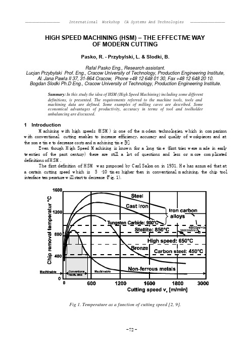
HIGH SPEED MACHINING (HSM) – THE EFFECTIVE WAYOF MODERN CUTTINGPasko, R. - Przybylski, L. & Slodki, B.Rafal Pasko Eng., Research assistant.Lucjan Przybylski Prof. Eng., Cracow University of Technology, Production Engineering Institute, Al. Jana Pawla II 37, 31-864 Cracow, Phone +48 12 648 01 30, Fax +48 12 648 20 10.Bogdan Slodki Ph.D Eng., Cracow University of Technology, Production Engineering Institute.Summary: In this study the idea of HSM (High Speed Machining) including some differentdefinitions, is presented. The requirements referred to the machine tools, tools andmachining data are defined. Some examples of milling caves are described. Someeconomical advantages of productivity, accuracy in terms of tool and toolholderunbalancing are discussed.1 IntroductionMachining with high speeds (HSM) is one of the modern technologies, which in comparison with conventional cutting enables to increase efficiency, accuracy and quality of workpieces and at the some time to decrease costs and machining time [9].Even though High Speed Machining is known for a long time (first tries were made in early twenties of the past century) there are still a lot of questions and less or more complicated definitions of HSM.The first definition of HSM was proposed by Carl Salomon in 1931. He has assumed that at a certain cutting speed which is 5 –10 times higher then in conventional machining, the chip tool interface temperature will start to decrease (Fig. 1).Fig 1. Temperature as a function of cutting speed [2, 9].It is not possible to verify this theory to its full extent based on recent experimental results. There is a relative decrease of the temperature at the cutting edge that starts at certain cutting speeds for different materials. Actually there are many different ways to define HSM, upon them HSM is said to be [2]:??high cutting speed machining (v c),??high rotational speed machining (n),??high feed machining (v f),??high speed and feed machining,??high productive machining.Practically, it can be noted that HSM is not simply high cutting speed. It should be regarded as a process where the operations are performed with very specific methods and production equipment [2]. HSM is not only machining with high spindle speed because many applications are performed with conventional spindle speeds. HSM is often used in finishing in hardened steels with both high speeds and feeds. HSM can be called rather the High Productive Machining when machining components in roughing to finishing and also in finishing to super-finishing in components of all sizes.2 Applications of High Speed MachiningThe use of HSM allow us to shorten the production time and to increase the accuracy of machined parts. High Speed Machining is being mainly used in three industry sectors due to their specific requirements [1].= ManualfinishingA) Traditional process. Non-hardened (soft) blank (1), roughing (2) and semi-finishing (3). Hardening to the final service condition (4). EDM process –machining of electrodes and EDM of small radii and corners at big depths (5).Finishing of parts of the cavity with good accessability (6). Manual finishing (7).B) Some process as (A) where the EDM-process has been replaced by finishmachining of the entire cavity with HSM (5). Reduction of one process step.C) The blank is hardened to the final service condition (1), roughing (2), semi-finishing (3) and finishing (4). HSM most often applied in all operations(especially in small sized tools). Reduction of two process steps. Normal timereduction compared with process (A) by approximately 30 – 50%.Fig. 2. Improvement of production process when using HSM [2].The first category is industry which deals with machining aluminum to produce automotive components, small computer parts or medical devices [1, 4, 10, 11]. This industry needs fast metal removal, because the technological process involves many machining operations.The second category which is aircraft industry involves machining of long aluminum parts, often with thin walls [1, 4, 10, 11].The third industry sector is the die mould industry which requires dealing with finishing of hard materials [2]. In this category it is important to machine with high speed and to keep high accuracy. In this industry HSM is used for machining such parts as [2]:Die casting dies. This is an area where HSM can be utilized in a productive way as most castings dies are made of demanding tool steels and have a moderate or small size.Forging dies. Most forging dies are suitable for HSM due to thir complex shape The surface is very hard and often prone cracks.Injection moulds and blow moulds are also suitable for HSM, because of their small sizes. Which makes it economical to perform all operations in one set up.Milling of electrodes in graphite and cooper. It is an excellent area for HSM. Graphite can be machined in a productive way with Ti(C,N), or diamond coated solid carbide endmills.Modelling and prototyping of dies and moulds. is one of the earliest area for HSM. Easy to machine materials such as non-ferrous, for example aluminum are used. The cutting speeds are often as high as 15 000 – 50 000 [rpm] and the feeds are also very high.Using of the HSM in the above mentioned regions can cause the reduction of production process when electrode milling ECM and EDM . HSM ensres a dimensional tolerance of 0,02 mm, while the tolerance when using ECM is 0,1 – 0,2 [mm] and EDM 0,01 – 0,02. Replacing ECM with machining causes the durability and tool life of the hardened die or mould is increased considerably.3 Some recommended parameters for HSMThere are some critical parameters for HSM, as for instance the depth of cut. The cutting tool manufacturers provide recommendations regarding the machining parameters that should be used [7]. Those parameters are usually one of many operating windows [7] (applicable sets of parameters).An increase of cutting speed to HSM values give several benefits such as enlarging of the removal rate and improving of the final surface (Fig. 3).Fig. 3. Comparison of production indexes during machining of a punch [3, 6, 8].64,316,5120,333,5c =20 [mm], a p =0.8 [mm], v c =100 [m/min], z =0.1 [mm/tooth] p =0.2 [mm], f z =0.05 [mm/tooth]1 – removal rate [cm 3/min]2 – surface roughnessRa [?m]Below there is a comparison of speeds used during machining some selected materials using conventional and HSM methods (Tab. 1).Table 1. Conventional vs. High Speed Machining [1].Solid Tools (end mills, drills) WC, coated WC, PCD, ceramic Indexable Tools (shell mills, face mills)WC, ceramic, sialon, CBN, PCDWork material Typical cutting speed [m/min] High cutting speed [m/min] Typical cutting speed [m/min] High cuttingspeed [m/min]aluminum >305 (WC, PCD) >3050 (WC, PCD) >610 >3658 (WC,PCD)soft 152 366 366 1219 (sialon,ceramic) cast ironductile 107 244 244 914 (ceramic)free mach. steel 107 366 366 610 alloy 76 244 213 366 stainless 107 152 152 274steel hardness HRC65 24 122 30 (WC) 91 (CBN, ceramic) 46 (WC) 183 (CBN,ceramic)titanium 38 61 46 91 superalloy 46 76 84 (WC) 213 (sialon) 366 (sialon,ceramic)As it was pointed out before HSM is mainly used in die mold industry. Below some typical cutting data for machining of die are selected in Tables 2 and 3.Table 2. Typical cutting data for solid carbide end mills with Ti(C,N) or TiAlN – coating in hardened steel: (HRC 54 – 58) [2]. Type of processing v c [m/min] a p [%] * a e [%]* f z [mm/tooth] Roughing 100 6 – 8 35 – 40 0,05 – 0,1 Semi –finishing150 – 200 3 – 4 20 – 40 0,05 – 0,15 Finishing andSuper-finishing 200 – 250 0,1 – 0,2** 0,1 – 0,2** 0,02 – 0,2* % of the cutter diameter, ** [mm]Table 3. HSM cutting data by experience (R – roughing, F – finishing) [2]. v c [m/min] Material* Hardness Conv. HSM – R HSM – F Steel 01.2 150 HB <300 >400 <900 Steel 02.1/2 330 HB <200 >250 <600 Steel 03.11 300 HB <100 >200 <400 Steel 03.11 39 – 48 HRC <80 >150 <350 Steel 04 48 – 58 HRC <40 >100 <250 GCI 08.1 180 HB <300 >500 <3000 Aluminum 60 – 75 HB <1000 >2000 <5000 Non-ferr. 100 HB <300 >1000 <2000* acording to Coromant Material Classification (CMC)During dry milling with those machining parameters compressed air or oil mist under high pressure is recommended.4 Toolholder and tool – unbalancing problemThe elements of the machine – tool subsystem that determine efficiency of high speed machining are: spindles, axes, motor drivers, toolholders and cutting tools. The spindle is probably the most critical element [1], so to maintain maximum productivity and accuracy it is important to ensure the run-out as small as possible. The smaller the run-out is, the shorter is the time between changing inserts in a milling cuter.Especially in HSM applications the size of run-out is crucial for accuracy [1, 5]. The Total Indicator Readout (TIR ) should be maximum 10 microns at the cutting edge [2]. Every 10 microns in added run-out gives 50% reduction of tool life. Even if the tool, toolholder, and spindle are precisely balanced, there still can be several sources of instability. One of the sources of instability is the fit between toolholder and spindle interface. There is often a measurable clearance in this grip. Moreover, it also may be a chip or dirt inside the taper. In practice, an endmill run at 20 000 rpm may not need to be balance to any better than 20 gmm, and 5 gmm is generally appropriate for much higher speeds. The Fig. 5 refers to unbalance force relating to the tool and adapter weight of 1.2 kg. [2]5 Machine tools for HSM – requirementsEven though high speed spindle options for conventional machining centers has been available for some time, it is only recently that machine tool designers and engineers have been developing the machines for HSM. As it was noted previously, HSM requires fitting of many parameters specified in Table 4, which are connected with the machine tools. Below are some typical demands on the machine tool and the data transfer in HSM (ISO/BT40 or c omparable size, 3 – axis).Table 4. Demands on the machine tool and the data transfer [2].??Spindle speed range<= 40 000 rpm??Spindle power > 22 kW??Programmable feed rate 40 –60 m/min??Rapid travels < 90 m/min ??Axis dec./acceleration> 1g (faster w. linear motors) ??Block processing speed1 – 20 ms??Data flow via Ethernet 250 kbit/s (1 ms)??Increments (linear) 5 – 20 ?m ??Circular interpolation viaNURBS (no linear increments) ??High thermal stability and rigidity in spindle – higher pretensionand cooling of spindle bearings ??Air blast/coolant through spindle ??Rigid machine frame with high vibration absorbing capacity ??Different error compensations – temperature, quadrant, ballscrew are most important??Advanced look ahead function in the CNC6 Machining methods for the die and mould manufacturingPractically, HSM is used to reduce the costs of workpiece production. Such a case takes place when machining press dies or moulds. As it is known dies consist of cavities in various shapes, with the dimensions and numerous radii sizes of corners. As an example methods for machining of a cavity below are described.Based on experience, or other production information, the surface machined, can be split up in segments. Each segment can be machined with one set of insert edges. This technique can be used both for roughing and finishing. It gives several benefits, namely [2] :better machine tool utilisation – less interruptions, less manual tool changing,higher productivity, i.e. easier to optimise cutting data,better cost efficiency – optimisation vs. real machine tool cost per hour,higher die or mould geometrical accuracy, which means the finishing tools can be changed before getting excessive wear.6.1. Methods for machining a cavityThere are several methods used for machining the cavity.One of them is to pre-drill of a starting hole. Corners can be pre-drilled as well. This method is not recommendable, because a special tool is needed. When the cutter breaks through the pre-drilled holes in the corner, the variations in the cutting forces and temperature appear negative from a cutting point of view. When using pre-drilled holes the re-cutting of chips also increases, (Fig. 5).Fig. 5. Example of machining a cavity withpredrill a starting hole [2].Fig. 6. Example of machining with a ball noseendmill [2].In the second method a ball nose end mill is applied. Thus it is common to use a peck-drilling cycle to reach full axial depth of the cut and then mill the first layer of the cavity. This is repeated until the cavity is finished as shown in Fig. 6 [2].One of the best methods is linear ramping in X/Y and Z to reach a full axial depth of the cut [2]. The inclination can start both from in to out or from out to in. It depends on the geometry of the die or mould. The main problem is how to evacuate of the chips in the best way. Down milling should be done with a continuous movement and continuous cutting. It is important to approach with ramping movement or even better with even circular interpolation, during changing to a new radial depth of cut. (Fig. 7)Fig. 7.Example of machining witch linearramping [2].Fig. 8. Example of machining witch rampingcapacity [2].The last method is effective when using round insert cutters or end mills with a ramping capacity. The best choice it is to take the first axial depth of cut using circular interpolation in helix the rest of machining goes as in the previous point. (Fig. 8)7 ConclusionHard competition causes rapid development of the machining technology and design of new solutions. High Speed Machining is proposed as an example. HSM ensures high metal removal rates, boost productivity, improve surface finish and eliminates the need of coolant. In spite of highrequirements of machining tools, HSM gives numerous benefits. It allows to shorten the productiontime and eliminates some treatment (e.g. manual finishing) beside simultaneously retaining the accuracy. These advantages are decisive for the use of HSM for machining the press dies. Even though HSM has been known for a long time, the research are still being developed for further improvement of quality and minimization of costs.8 References[1] Ashley S., High – speed machining goes mainstream, Mechanical Engineering, May 1995,(56 – 61).[2] Die & Mould Making Application Guide, Sandvik Coromant, 1999.[3] Fraisage a grande vitesse, Fabrication des outillages: des resultats spectaculaires, L’UsineNouvelle, 1995, 16.02, nr 2490, (46 – 48).[4] Grzesik W., Podstawy skrawania materialów metalowych, WNT, Warszawa, 1998.[5] Mason F., Die and mold finishing. How fast?, Manuf. Eng. 1995, t. 115, nr 3, s. 35-36,39-40,42, 45, 47-48.[6] Materialy z IV-go Sympozjum z cyklu “Formy wtryskowe i odlewnicze”, Miarki, maj 1997.[7] Plaza M., The prons and cons of high-speed machining, Canadian Machinery andMetalworking, Sep. 1995, (8 – 10).[8] Przybylski L., Monolityczne frezy trzpieniowe z weglików spiekanych nowej generacji, IIOgólnokrajowa Konferencja Naukowo – Techniczna “Jakosc w budowie obrabiarek itechnologii maszyn”, Kraków, 1997, (115 – 121).[9] Schulz H., Moriwaki T., High – speed machining, Ann. of the CIRP, 1992, t. 41, nr 2, s. 637 –642.[10] Szewczyk A., Wybrane zespoly i wyposazenie obrabiarek do obróbki z wysokimipredkosciami skrawania, Prace IOS, seria Opracowania Analityczno-Syntetyczne, 1993, nr 3. [11] Tlusty J., High – speed machining, Ann. of the CIRP, 1993, t. 42, nr 2, s. 733 – 738.。
中英文文献翻译-组合机床与控制设计

英语原文:Integrated Machine and Control DesignAbstract—In this paper, we describe a systematic design procedure for reconfigurable machine tools and their associated control systems. The starting point for the design is a set of operations that must be performed on a given part or part family. These operations are decomposed into a set of functions that the machine must perform and the functions are mapped to machine modules, each of which has an associated machine control module. Once the machine is constructed from a set of modules, the machine control modules are connected. An operation sequence control mod ule, user interface control module, and mode-switching logic complete the control design. The integration of the machine and control design and the reconfigurability of the resulting machine tool are described in detail.I. IntroductionIn today’s competitive markets, manufacturing systems must quickly respond to changing customer demands and diminishing product life cycles. Traditional transfer lines are designed for high volume production, operate in a fixed automation paradigm, and therefore cannot readily accommodate changes in the product design. On the other hand, conventional CNC-based “flexible” manufacturing system offer generalized flexibility but are generally slow and expensive since they are not optimized for any particular product or a family of products.An effort at the University of Michigan aims to develop the theory and enabling technology for reconfigurable machining systems. Instead of building a machining system from scratch each time a new part is needed, an existing system can be reconfigured to produce the new part. In this paper, we describe how an integrated machine and control design strategy can result in machine tools which can be quickly and easily configured and reconfigured.In order to provide exactly the functionality and capacity needed to process a family of parts, RMTs are designed around a given family of parts. Given a set of operations to be performed, RMTs can be configured by assembling appropriate machine modules. Each active module in the library has a control module associated with it. As the mechanical modules are assembled, the control modules will be connected and the machine will be ready to operate. Extensive and time-consuming specialized control system design will not be required. Section II describes how the machine is designed from a set of basic machine modules,This research was supported in part by the NSF-ERC connected in a well-defined fashion, and Section III describes how the control is similarly assembled from a library of control modules. This modular construction of the machine and control allows formany levels of reconfigurability as described in Section IV. The paper concludes with a description of future work in Section V.II. Machine DesignOngoing work on manufacturing system configuration at the University of Michigan addresses the problem of starting from a part (or part family) description and extracting the machining operations necessary to produce the part(s). The operations are grouped according to tolerance, order of execution, and desired cycle time of the system, with the intention that each operation “cluster” can be produced on a single machine tool. The operation cluster considered here is to drill a set of holes for the cam tower caps on V6 and V8 cylinder heads shown in Figure 1. The input to the reconfigurable machine tool design procedure is the cutter location data generated by a process planner for this operation cluster. data includes positioning and drilling information.The RMT design procedure consists of three main stages: task clarification, module selection, and evaluation. After a brief literature review, these three stages will be outlined in this section.A. Related researchSince reconfigurability is a relatively new concept in ma chining systems, there is little, if any, published literature on the design of reconfigurable machine tools. However, modular machine tools have been on the market for several years, and some of the published articles on modular robots, modular machines and assembly do have some rel-evance to the design of reconfigurable machine tools. For example, Shinno and Ito proposed a methodology for generating the structural configuration of machine tools. They decomposed the machine tool structures into simple geometric forms: e.g. boxes, cylinders, etc. Yan and Chen [21], [1] extended this work to the ma chining center structural design. [12] adapted Ito’s method for modular machine t ool synthesis and de-veloped a method for enumerating machine tool modules. Paradis and Khosla [15] determined the modular assembly configuration which is optimally suited to perform a specific task. On the systems front, Rogers and Bottaci [16] discussed the significance of reconfigurable manufacturing systems, and Owen et al. [13] developed a modular reconfigurable manufacturing system synthesis program for educational pur poses.In our work, traditional methods of motion representation and topology (i.e. screw theory, graph theory, etc.) are employed to capture the characteristics of RMTs. These mathematical schemes are used for topological synthesis, function-decomposition, and mapping procedures; details can be found in [9].Figure 1B.Task clarificationThe design of an RMT begins with task clarification, which entails analyzing the cutter location data to determine the set of functions which are necessary to accomplish the desired kinematic motions. There are three steps. First, graphs are generated which abstractly representationFig. 3. High-level operation sequence, showing causal dependencies and concurrencies.This abstract representation of the sequence of operations is derived from the CL data, and will be used to design the sequencing control the motions. These graphs are then decomposed into functions, and finally the functions are mapped onto machine modules which exist in the library.A graph representation of the machine tool structure allows for systematic enumeration of alternate configurations and also provides a method of identification of nonisomorphic graphs. The graph representation is also used for bookkeeping to assign machine modules to the graph elements. A graph consists of a set of vertices connected together by edges. In using a graph as an abstract represen tation of a machine tool structure, we define two different types of vertices: type 0 and type 1. A vertex represents a physical object with two ports; each port represents the location on the object where it can be attached to a neighboring object. A type 0 vertex has input and output ports that are in-line with respect to each other, whereas a type 1 vertex has input and output ports that are perpendicular to each other. Machining tasks are also classified as type 0 or type 1, depending on whether the tool is parallel or per pendicular to the workpiece.C. Module selectionCommercially available modules are selected from the module library for each ofthe functions (structural as well as kinematic) that were mapped to the graph in the task clarification stage. The data stored for each module in the library includes the homogenous transformation matrix representing its kinematic or structural function, the twist vector supplemented by range of motion information, a compliance matrix representing the module stiffness, module connectivity information, and power requirements (for active modules such as spindles and slides).The first step in module selection is to compare the homogeneous transformation matrices of the modules with the task requirement matrix such that when appropriate modules are selected to meet the task requirements, the product of all module matrices should be equal to the desired task matrix: T = T1· T2 · · · Tn. Again, there may be many possible choices of modules for a given structural configuration. Figure 6 shows how different slides, spindles, and structural elements can be assembled according to the graph of Figure 4.A slide module, with its CAD model and transformation matrix, is shown in Figure7. It is capable of one direction of linear motion, indicated by the ~1 variable in its transformation matrix. Its database entry, shown in Table I, stores not only its transformation matrix but also the manufacturer name, model number, initial position, power level, and motion data. The twist vector is augmented by information on the minimum, initial, and maximum displacement of the module.TABLE IDatabase information and documentation for the machinemodule shown in Figure 7.(a) V6 machine (b) V8 machineFig. 2. Reconfigurable machine tool designs for the two different parts.D. EvaluationOnce a set of kinematically-feasible modules have been selected, the resulting machine design must be evaluated. The criteria for evaluation of the reconfigurable machine tools synthesized by the above systematic procedure include the work envelope, the number of degrees of freedom, the number of modules used, and the dynamic stiffness.The number of kinematic degrees of freedom of the machine tool must be kept to a minimum required to meet the requirements, both to reduce the actuation power and minimize the chain of errors. Machine tool designs which are generated using this methodology for the example parts of Figure 1 are shown in Figure 8.The resulting designs must be evaluated with respect to the expec ted accuracy. The stiffness of the entire machine tool, one of the most important factors in performance, is estimated based on the module compliance matrices and the connection method.III. Control DesignAs the machine is built from modular elements, so is the control. In this work, we focus on the logic control for sequencing and coordination of the machine modules; a discrete-event system formalism is used [6]. There is one control module associated with each active machine module; we refer to these as machine control modules. In the machine design, there are passive elements which connect the active elements together. In the control design, there must also be“glue” modules which connect the machine control modules. The overall architecture of the control system for an RMT is shown in Figure 9.The structure is similar for either of the two machines shown in Figure 8; for the V8 machine, there is no Y -axis control module. As shown, the machine control modules are at the lowest level; these interact directly with the mechanical system. Three modules handle the mode switching logic. In this section, we briefly describe each of these types of control modules as well as their interaction and coordina tion.A. Machine control modulesEach machine control module has awell-defined interface specification: itaccepts discrete-event commands from agiven set, and returns discrete-eventresponses from a given set. Within thecontrol module will be all of the continuous-variable control, such as servo control foraxes. This continuous control is designedusing standard PID algorithms and the axisparameters such as inertia, power, lead screw pitch, which come from the machine module definition. In addition, each machine control module will contain con trols for any machine services associated with the machine module, such as lubrication or coolant. Thus, each machine control module is a self-contained controller for the machinemodule itaccompanies, and can bedesigned andtestedindependentlyof the rest ofthe machine.Fig.10.Slide ControllerThe design of a machine control module must be done only once for each machine module in the library. Whenever the machine module is used in a machine design, the control module can be used in the associated control design. The control module may be used independently, with its own processing power, I/O and a network connection to the rest of the control system, or it may be used as a piece of the overall machine controller which is implemented in a centralized fashion.B. Operation sequenceThe operation sequence module is defined from the high level sequence extracted from the cutter location data shown in Figure 3.C. Modular control structureThe user interface control module interacts with the user through a set of pushbuttons to turn the control system on and off, switch between control modes, and single-step through the operation sequence. Its main functions are to pass the user commands through to the rest of the controller, and to display the current state of the machine to the user.IV. Conclusions and Future WorkHistorically, machine tool design has been experience based. In this research, we described a mathematical basis for synthesis and evaluation of Reconfigurable Machine Tools and their associated controllers. This research work has addressed both the generation of machine tool configurations and modular control design. The systematic design process begins with the machining requirements.The presented methodology for synthesis of machine tools allows a library of machine modules to be precompiled and stored in a database, self-contained with con-trollers and ready to be used in any machine design. The methodology also ensures that all kinematically viable and distinctly different configurations are systematically enu-merated to reduce the chance of missing a good design.We have already developed a Java-based program which automates the machinedesign process; we are currently incorporating the control design procedure withi n the existing framework.The authors would like to acknowledge the support and invaluable feedback from the industrial members of the ERC who have participated in this project.中文译文组合机床与控制设计摘要——在本文中,我们描述一个系统的设计程序的可重构机床及其控制系统。
文献翻译-多用途组合机床

英文原文Multi-purpose aggregate machine-tool timeRegarding the multi-purpose aggregate machine-tools, in the industrial field has many names to describe it, like “the multitasking installment”, “the multi-purpose engine beds”, “the multi-procedure production system” and so on, it may be called the processing domain truly the nova, may reduce the cost, the simplified disposition, and has maintained in the US territory produces. Inthe past only then used the duty which many machine operations could complete, now may concentrate to an engine bed on processes completes.As a result of market demand's unceasing change, the product life cycle is reducing unceasingly, today's market more intense demand multitasking installment concept. Carries out the fine profit management when the entire production environment, compared to having not concentrated the components processing to a machine on completes a finer profit.Some tradition's manufacturing industry manufacturer thought that the multi-purpose aggregate machine-tools are too complex,very difficult to find the appropriate operators also the difficult problem innovates on the spot on the insufficiency for the metal working Basic principle and in the Production workshop related new engine bed use solution aspect training.Intuition type technical controlThe equipment use “carries off the quantity of heat” the type design, has different material which the lathe bed, the steeliness straight line rolling guide, on the steeliness revolving tool box saddle, the equipment uses, all these combine make an engine bed together. These with the thermal conductivity, the volume expansion are related. All different size's thing can by the different speed growth.As a result of this reason, needs to make the hot friendly engine bed, with the aim of knowing gives off heat the weak point in where, can compensate through the reasonable engine bed design. The part is the entire journey movement. The engine bed glide produces rubs and transform hotly. The machining produces the hot filings fall to the different place, the refrigerant can mix in the entire process in which. Will present the different temperature province continually on the cutting tool, will therefore also have many things to have the influence to the thermostability. The cutting tool technology turned the multi-purpose aggregate machine-tools has had the milling and cutting power “the versatile machine”.According to the material introduced that the most remarkable characteristic is in these engine bed whole has the intuition. The anti-collision preservation technology was already mature, in certain circumstances, even if uses the manual operation pattern, can also avoid the occurrence which collides. Because the control software has the very good intuition, the user operation friendly degree unceasingly is also enhancing. Believe the multi-purpose aggregate machine-tools by its survivability world-wide in the more different processing scenes.The off-line programming optimization and the NC automatic control system's formation already made this technology to be easier to accept, when therefore uses the procedure when the engine bed, does not need to spend many time tune-up procedure and confirmed that some part does not have the question. If components need to provide the high and low two revolving tool box saddle simultaneously to carry on the rough machining, in this kind of situation the programming is quite difficult, because it needs two revolving tool box saddles also to feed. The AdMac system may realize tool rest's automatic programming which simultaneously feeds to these, and can cause the correct main axle speed, the correct feed rate and so on all parameters to realize the synchronization.Okuma Corporation's collision avoidance system design based on actual processing operating mode anti-collision simulation, therefore, if the operator has installed the wrong cutting tool or has established the wrong parameter, the control system will examine and prevents the engine bed to enter the processing condition. Through cooperates with the Siemens, INDEX Corporation may provide the 3D pattern now “the hypothesized engine bed”, has custom-made according to some specific model's engine bed. The result indicated that the simulation processes not only the fabricated parts and the actual end product is similar, is the one-to-one copy simply.The intuition type control interface, the simulation as well as other software technique are progressive, the more Production workshops have opened wide the front door to the multi-purpose aggregate machine-tools, but if does not have the corresponding knowledge to train and to solve the question creativity, the manufacturer is also very difficult to realize and the full use advanced engine bed flexibility aspect superiority. The work which does to the machine are more, the machine will be more complex, also needs to have the stronger skill person correspondingly to be able to operate it.If machinist past one day operated 3 engine beds, then he has this kind of multi-purpose engine bed now, might produce more components. More importantly, he may draw support from software's help to cause the production efficiency to be higher, regarding transformation processing components preparation, may also establish the processing craft plan. Because the replacement components need to lower 3 main axles, therefore before replacing the components, the workshop should process as far as possible many components. Regarding the multi-purpose engine beds, the transformation components speed is quick, the production batch of time interval is shorter, the stock is lower, the production efficiency is higher. Can use multi-purpose engine bed's some workshops fully, very quick will discover the post function the unification. Now, a workshop may only use an operator, an adjuster and a programming teacher, in the future these 3 work definitely may do by a person.In the traditional post description the machinist will transit becomes one to adjust engineer, if this engineer the familiar components processing programming, that were also more ideal. Regarding such transformation, training has been simple, so long as trains 1 individual line, but is not 3individuals. Looking from the long views, this will provide to the people the higher post degree of satisfaction. When adjusts engineer to be responsible to process the programming, and pays attention to the components processing personally time the entire process, he completely has become this components control. In addition, but should also makes more effort in the cutting tool choice and the programming aspect, must make any model the multi-purpose aggregate machine-tool to succeed, the workshop needs to provide the skilled machinist, has ability and completes many kinds of operations nimbly. Therefore, crosswise training was at any time in the past more important. Regarded as the milling and the lathe work the different belongs to their time. Regarding personnel who will program, will understand the engine bed and controls it, this will be their ability manifestation.The cutting tool will choose most people not to install the passenger vehicle tire to the race car on, but processed the cutting tool to have such situation. The cutting tool should match with the new engine bed, is conceivably redundant on the new engine bed uses the old cutting tool to the production efficiency influence. In order to match the multi-purpose aggregate machine-tools, the new cutting tool and the cutting tool adapter technology was already developed. At present the industrial field is developing the development the processing cutting tool, may complete the turning on the identical tool rest, boring and drills truncates the processing, is only processes the phase to differ from regarding the work piece angle. The processing operates the difference even confuses is unclear. The new processing cutting tool may complete the milling and the turning. The machinery automation technology first starts from the 1920s in the machine manufacture cold finishing production in enormous quantities process to develop the application, after in the 60s, to adapt the market demand and the change, for the enhancement machine-building industry to the market nimble rapid reaction's ability, starts to establish the variable automation production system,namely revolves the computer technology the flexible automation. It is in the manufacture system invariable or in the change small situation, the machinery equipment either production management process through the automatic detection, the information processing, the analysis judgment realizes the anticipated operation or some kind of process automatically, and can from make one kind of components to transform automatically to makes another kind of different components. The social practice proved that under this kind of definition's manufacture system automation and the contemporary majority enterprises are not actually accommodating. The contemporary society also not in the science and technology, the material and the personnel aspect prepares to realize this automated condition, insists such to do only meets the wasted effort. This kind of situation is not exceptional regarding the separate production method's machine-building industry, the difficulty can bigger.The aggregate machine-tool future development more use transmissions and so on variable speed motor and ball bearing guide screw,will simplify structure, the reduction production metre; Uses the numerical control system and the headstock, the jig automatic replacement system, enhancesthe craft controllability; As well as integrates the flexible manufacture system and so on.中文译文多用途组合机床对于多功能组合机床,在工业领域有许多名字来描述它,如“多任务处理装置”,“多功能机床”,“多工序生产系统”等,它确实可称为加工领域的新星,可降低成本,简化配置,和一直保持在美国本土生产。
- 1、下载文档前请自行甄别文档内容的完整性,平台不提供额外的编辑、内容补充、找答案等附加服务。
- 2、"仅部分预览"的文档,不可在线预览部分如存在完整性等问题,可反馈申请退款(可完整预览的文档不适用该条件!)。
- 3、如文档侵犯您的权益,请联系客服反馈,我们会尽快为您处理(人工客服工作时间:9:00-18:30)。
英文原文Multi-purpose aggregate machine-tool timeRegarding the multi-purpose aggregate machine-tools, in the industrial field has many names to describe it, like “the multitasking installment”, “the multi-purpose engine beds”, “the multi-procedure production system” and so on, it may be called the processing domain truly the nova, may reduce the cost, the simplified disposition, and has maintained in the US territory produces. Inthe past only then used the duty which many machine operations could complete, now may concentrate to an engine bed on processes completes.As a result of market demand's unceasing change, the product life cycle is reducing unceasingly, today's market more intense demand multitasking installment concept. Carries out the fine profit management when the entire production environment, compared to having not concentrated the components processing to a machine on completes a finer profit.Some tradition's manufacturing industry manufacturer thought that the multi-purpose aggregate machine-tools are too complex,very difficult to find the appropriate operators also the difficult problem innovates on the spot on the insufficiency for the metal working Basic principle and in the Production workshop related new engine bed use solution aspect training.Intuition type technical controlThe equipment use “carries off the quantity of heat” the type design, has different material which the lathe bed, the steeliness straight line rolling guide, on the steeliness revolving tool box saddle, the equipment uses, all these combine make an engine bed together. These with the thermal conductivity, the volume expansion are related. All different size's thing can by the different speed growth.As a result of this reason, needs to make the hot friendly engine bed, with the aim of knowing gives off heat the weak point in where, can compensate through the reasonable engine bed design. The part is the entire journey movement. The engine bed glide produces rubs and transform hotly. The machining produces the hot filings fall to the different place, the refrigerant can mix in the entire process in which. Will present the different temperature province continually on the cutting tool, will therefore also have many things to have the influence to the thermostability. The cutting tool technology turned the multi-purpose aggregate machine-tools has had the milling and cutting power “the versatile machine”.According to the material introduced that the most remarkable characteristic is in these engine bed whole has the intuition. The anti-collision preservation technology was already mature, in certain circumstances, even if uses the manual operation pattern, can also avoid the occurrence which collides. Because the control software has the very good intuition, the user operation friendly degree unceasingly is also enhancing. Believe the multi-purpose aggregate machine-tools by its survivability world-wide in the more different processing scenes.The off-line programming optimization and the NC automatic control system's formation already made this technology to be easier to accept, when therefore uses the procedure when the engine bed, does not need to spend many time tune-up procedure and confirmed that some part does not have the question. If components need to provide the high and low two revolving tool box saddle simultaneously to carry on the rough machining, in this kind of situation the programming is quite difficult, because it needs two revolving tool box saddles also to feed. The AdMac system may realize tool rest's automatic programming which simultaneously feeds to these, and can cause the correct main axle speed, the correct feed rate and so on all parameters to realize the synchronization.Okuma Corporation's collision avoidance system design based on actual processing operating mode anti-collision simulation, therefore, if the operator has installed the wrong cutting tool or has established the wrong parameter, the control system will examine and prevents the engine bed to enter the processing condition. Through cooperates with the Siemens, INDEX Corporation may provide the 3D pattern now “the hypothesized engine bed”, has custom-made according to some specific model's engine bed. The result indicated that the simulation processes not only the fabricated parts and the actual end product is similar, is the one-to-one copy simply.The intuition type control interface, the simulation as well as other software technique are progressive, the more Production workshops have opened wide the front door to the multi-purpose aggregate machine-tools, but if does not have the corresponding knowledge to train and to solve the question creativity, the manufacturer is also very difficult to realize and the full use advanced engine bed flexibility aspect superiority. The work which does to the machine are more, the machine will be more complex, also needs to have the stronger skill person correspondingly to be able to operate it.If machinist past one day operated 3 engine beds, then he has this kind of multi-purpose engine bed now, might produce more components. More importantly, he may draw support from software's help to cause the production efficiency to be higher, regarding transformation processing components preparation, may also establish the processing craft plan. Because the replacement components need to lower 3 main axles, therefore before replacing the components, the workshop should process as far as possible many components. Regarding the multi-purpose engine beds, the transformation components speed is quick, the production batch of time interval is shorter, the stock is lower, the production efficiency is higher. Can use multi-purpose engine bed's some workshops fully, very quick will discover the post function the unification. Now, a workshop may only use an operator, an adjuster and a programming teacher, in the future these 3 work definitely may do by a person.In the traditional post description the machinist will transit becomes one to adjust engineer, if this engineer the familiar components processing programming, that were also more ideal. Regarding such transformation, training has been simple, so long as trains 1 individual line, but is not 3individuals. Looking from the long views, this will provide to the people the higher post degree of satisfaction. When adjusts engineer to be responsible to process the programming, and pays attention to the components processing personally time the entire process, he completely has become this components control. In addition, but should also makes more effort in the cutting tool choice and the programming aspect, must make any model the multi-purpose aggregate machine-tool to succeed, the workshop needs to provide the skilled machinist, has ability and completes many kinds of operations nimbly. Therefore, crosswise training was at any time in the past more important. Regarded as the milling and the lathe work the different belongs to their time. Regarding personnel who will program, will understand the engine bed and controls it, this will be their ability manifestation.The cutting tool will choose most people not to install the passenger vehicle tire to the race car on, but processed the cutting tool to have such situation. The cutting tool should match with the new engine bed, is conceivably redundant on the new engine bed uses the old cutting tool to the production efficiency influence. In order to match the multi-purpose aggregate machine-tools, the new cutting tool and the cutting tool adapter technology was already developed. At present the industrial field is developing the development the processing cutting tool, may complete the turning on the identical tool rest, boring and drills truncates the processing, is only processes the phase to differ from regarding the work piece angle. The processing operates the difference even confuses is unclear. The new processing cutting tool may complete the milling and the turning. The machinery automation technology first starts from the 1920s in the machine manufacture cold finishing production in enormous quantities process to develop the application, after in the 60s, to adapt the market demand and the change, for the enhancement machine-building industry to the market nimble rapid reaction's ability, starts to establish the variable automation production system,namely revolves the computer technology the flexible automation. It is in the manufacture system invariable or in the change small situation, the machinery equipment either production management process through the automatic detection, the information processing, the analysis judgment realizes the anticipated operation or some kind of process automatically, and can from make one kind of components to transform automatically to makes another kind of different components. The social practice proved that under this kind of definition's manufacture system automation and the contemporary majority enterprises are not actually accommodating. The contemporary society also not in the science and technology, the material and the personnel aspect prepares to realize this automated condition, insists such to do only meets the wasted effort. This kind of situation is not exceptional regarding the separate production method's machine-building industry, the difficulty can bigger.The aggregate machine-tool future development more use transmissions and so on variable speed motor and ball bearing guide screw,will simplify structure, the reduction production metre; Uses the numerical control system and the headstock, the jig automatic replacement system, enhancesthe craft controllability; As well as integrates the flexible manufacture system and so on.中文译文多用途组合机床对于多功能组合机床,在工业领域有许多名字来描述它,如“多任务处理装置”,“多功能机床”,“多工序生产系统”等,它确实可称为加工领域的新星,可降低成本,简化配置,和一直保持在美国本土生产。