福斯定位器用户指导说明书
福斯LogiIQ智能定位器调试说明

福斯L o g i I Q智能定位器调试说明This model paper was revised by LINDA on December 15, 2012.Logix3200IQ智能定位器调试说明一、简介Logix3200IQ智能定位器接受4-20mA模拟量输入,4-20mA模拟量输出。
二、定位器操作面板介绍Logix3200IQ智能定位器就地操作面板由能够自动调校零点和满量程的QUICK-CAL快速调校按钮与可以手动操作定位器的两个点动按钮(↑和↓)以及八个DIP开关和可以调节定位器增益的旋转开关组成。
三、定位器DIP开关的设置定位器运行之前,首先设置DIP开关,下面就每一个DIP开关的设置进行了说明1、作用方式作用方式分气开式(ATO)和气关式(ATC)两种,调试前根据阀门的类型进行设置。
2、阀门关闭的信号4mA信号4mA时阀门处于全关位置,信号20mA时阀门处于全开位置 20mA信号20mA 时阀门处于全关位置,信号4mA时阀门处于全开位置3、阀位与信号对应曲线线性曲线(Linear)阀门位置与信号成线性关系选择曲线(Optional)选择了这个按钮,就激活了下一个DIP开关4、可选择曲线%=阀位与信号成等百分比 Custom用户自定义曲线5、自动校准on 每次按动QUICK-CAL按钮,定位器就自动调整参数进行调试 off每次调试时,只能根据出厂前的预设置即调节定位器增益的旋转开关的位置进行调试无论哪一种情况,调节定位器增益的旋转开关都可以进行调节,调节完毕,不用重新进行调试,是即时生效的。
6、稳定性开关Low-FrictionValves 适用低摩擦力调节阀 High-Friction Valves适用高摩擦力调节阀7、备用开关8、定位器调试方式Auto 定位器自动调试 Jog手动调试,用户可以根据需要手动确定阀门的100%的位置四、手动点动调试首先将调校DIP开关拨到Jog位置,用户只能手动设置满量程,不能设置全关位,阀门全关位为默认状态。
Fisher定位器使用说明书
Fisher定位器使用说明书一、Fisher定位器调校基本步骤1.将375手操器连接到接线端子上,进入菜单选择 Setup(设置)→Basic setup(基本设置)→Auto setup(自动设置)→Setup wizard(设置向导)2.根据Setup wizard的提示选择相应的参数⑴instrument mode is in service ,continue for prompts to pleaseout of service.仪表模式是在线状态,继续须要准时设置为离线状态选择 Yes.⑵output will not track input when instrument mode is out ofservice.当仪表在离线状态时,仪表的输出将不随输入的变化而变化选择Yes.⑶change to out of service to continue.继续需改变为离线模式选择out of service选择enter说明:仪表正常工作时其模式为in service状态,当对仪表进行调校时需改为out of service状态。
⑷Tru/Press select 行程/压力选择选择Travel control⑸Pressure units 压力单位选择psi⑹Max supply press 最大供气压力此时输入的最大供气压力值应与空气过滤减压阀的输出压力一致,此值不宜过大,过大,阀门易损坏,超行程。
应调整空气过滤减压阀使阀门刚好全行程,这时输入此时的压力值。
⑺Actuator manufacturer 执行机构制造商选择Fisher controls⑻Actuator model 执行机构型号查看阀体上的铭牌,有此执行机构型号,选择相应型号,如667,1035,1051等。
⑼Actuator size 执行机构尺寸查看阀体上的铭牌,有此执行机构尺寸,选择相应尺寸,如30,34,40,45,50,46,60,70,100等。
福斯FLOWSERVE阀门定位器

福斯FLOWSER阀门定位器福斯定位器配置指南福斯(FLOWSERV阀门定位器调试方法(锦菲特I3599429OO2)[Q-Q,6696 22933]flowserve 阀门、Flowserve 3400IQ 定位器、LOGIX500、LOGIX510、LOGIX520 D3系列P-5 气动定位器电动气动数字-通用,IS和EXHART、Profibus 、Foundation 现场总线反馈机组、限位开关比如PP5XX-HPGU-23K01-PV9DA-3ZPMV P-1700 系列阀门专为腐蚀或高温环境应用设计,其所有外部零件均由不锈钢制造而成。
P-1700 和1720 型阀门的内部零件采用不锈钢制造,而P-1710 和P-1730 型阀门的内部零件则采用铝制。
P-1720 和P-1730 型阀门具有超高的空气传送能力。
P-1700 系列阀门专为双向操作应用设计,不过也可通过旋动一个阀座轻松实现单向操作。
不锈钢磁场外壳内的PMV I/P转换器很容易安装在P-1700 系列阀门上。
P-1500 P-1520P-1700 P-1720P-1710 P-1730Digital 具有PID 控制的2000 数字定位器品牌Logix说明福斯Logix 2000 是一款具有板载PID 控制的数字定位器。
通信方式为4-20mA 或Modbus。
阀门上安装的PID 控制器每秒更新阀杆位置16 次,从而减少了控制系统延迟。
Logix 3200IQ 数字定位器3200IQ-10-D6-M-04-40-0G-0F 3200IQ-10-D6-M-04-40-0G-00品牌Logix说明福斯Logix 3200IQ 数字HART? 定位器使用先进的piezo 技术提供一流的性能和可靠性。
通过使用本地按钮、HART手持设备和SoftTools 软件可轻松配置Logix 3200IQ 。
LOGIX 3201IQ定位器P/N : 215809.999.000,SN 4107028LOGIX 3202IQ定位器P/N : 221734.999.000,SN 4907010LOGIX 3203IQ定位器P/N : 216428.999.000,SN 610727 定位器P/N:215809.999.000,SN:55070043400IQ Digital Positioner品牌Logix说明The Flowserve Logix 3400 Series digital Foundation? Fieldbuspositioner utilizes state-of-the-art piezo technology to provide …500 数字定位器品牌Logix说明福斯Logix 500 数字定位器是下一代本质安全型Logix 500 系列的代表。
福斯定位器配置指南
福斯定位器配置指南福斯(FLOWSERVE)阀门定位器调试方法(锦菲特I3599429OO2)[Q-Q,6696 22933]flowserve阀门、Flowserve 3400IQ定位器、LOGIX500、LOGIX510、LOGIX520、D3系列P-5 气动定位器电动气动数字- 通用,IS 和EXHART、Profibus、Foundation 现场总线反馈机组、限位开关比如PP5XX-HPGU-23K01-PV9DA-3ZPMV P-1700 系列阀门专为腐蚀或高温环境应用设计,其所有外部零件均由不锈钢制造而成。
P-1700 和1720 型阀门的内部零件采用不锈钢制造,而P-1710 和P-1730 型阀门的内部零件则采用铝制。
P-1720 和P-1730 型阀门具有超高的空气传送能力。
P-1700 系列阀门专为双向操作应用设计,不过也可通过旋动一个阀座轻松实现单向操作。
不锈钢磁场外壳内的PMV I/P 转换器很容易安装在P-1700 系列阀门上。
P-1500 P-1520P-1700 P-1720P-1710 P-1730Digital具有PID 控制的2000 数字定位器品牌Logix说明福斯Logix 2000 是一款具有板载PID 控制的数字定位器。
通信方式为4-20mA 或Modbus。
阀门上安装的PID 控制器每秒更新阀杆位置16 次,从而减少了控制系统延迟。
Logix3200IQ 数字定位器3200IQ-10-D6-M-04-40-0G-0F3200IQ-10-D6-M-04-40-0G-00品牌Logix说明福斯Logix 3200IQ 数字HART? 定位器使用先进的piezo 技术提供一流的性能和可靠性。
通过使用本地按钮、HART 手持设备和SoftTools软件可轻松配置Logix 3200IQ。
LOGIX 3201IQ定位器P/N:215809.999.000,SN:4107028LOGIX 3202IQ定位器P/N:221734.999.000,SN:4907010LOGIX 3203IQ定位器P/N:216428.999.000,SN:610727定位器P/N:215809.999.000,SN:55070043400IQ Digital Positioner品牌Logix说明The Flowserve Logix 3400 Series digital Foundation? Fieldbuspositioner utilizes state-of-the-art piezo technology to provide…500 数字定位器品牌Logix说明福斯Logix 500 数字定位器是下一代本质安全型Logix 500 系列的代表。
logix520福斯定位器说明书
Logix 520MD系列数字定位器FCD LGENIM0520-00用户指导说明书安装操作维护实践中积累经验目录页码基本信息............................................................................................. 2 拆箱..................................................................................................... 3 Logix 520MD 概要............................................................................... 4 技术参数............................................................................................. 4 工作原理............................................................................................. 5 气路连接.............................................................................................. 6 接线..................................................................................................... 6 电缆要求.............................................................................................. 7 调试..................................................................................................... 8 Logix 520MD 就地界面操作............................................................ 8 配置Dip 开关设置的操作................................................................ 8 校准开关........................................................................................ 9 快速校准操作................................................................................. 9 恢复出厂设置................................................................................. 10 4-20 mA 模拟输出板....................................................................... 10 错误代码.............................................................................................. 12 故障排除.............................................................................................. 15 限位开关............................................................................................. 16 备件包................................................................................................. 17 尺寸图. (18)1 正确使用福斯阀门福斯阀门、、执行执行器和附件器和附件 1.1手册手册使用使用使用说明说明以下指导说明用于帮助对福斯产品进行拆箱、安装和性能维护。
Fisher定位器使用说明书

Fisher定位器使用说明书一、Fisher定位器调校基本步骤1.将375手操器连接到接线端子上,进入菜单选择Setup(设置)→Basicsetup(基本设置)→Autosetup(自动设置)→Setup wizard(设置向导)2.根据Setup wizard的提示选择相应的参数⑴instrument mode is in service ,continue for prompts to pleaseout of service.仪表模式是在线状态,继续须要准时设置为离线状态选择Yes.⑵output will not track input when instrument mode is out ofservice.当仪表在离线状态时,仪表的输出将不随输入的变化而变化选择Yes.⑶change to out of service to continue.继续需改变为离线模式选择out of service选择enter说明:仪表正常工作时其模式为in service状态,当对仪表进行调校时需改为out of service状态。
⑷Tru/Press select行程/压力选择选择Travel control⑸Pressure units压力单位选择psi⑹Max supply press最大供气压力此时输入的最大供气压力值应与空气过滤减压阀的输出压力一致,此值不宜过大,过大,阀门易损坏,超行程。
应调整空气过滤减压阀使阀门刚好全行程,这时输入此时的压力值。
⑺Actuator manufacturer执行机构制造商选择Fisher controls⑻Actuator model执行机构型号查看阀体上的铭牌,有此执行机构型号,选择相应型号,如667,1035,1051等。
⑼Actuator size执行机构尺寸查看阀体上的铭牌,有此执行机构尺寸,选择相应尺寸,如30,34,40,45,50,46,60,70,100等。
福斯FLOWSERVE阀门定位器调试方法
福斯FLOWSERVE阀门定位器调试方法概述:福斯FLOWSERVE阀门定位器是一种用于控制阀门开度的装置,具有自动控制和调节阀门的功能。
在使用过程中,为了确保阀门的正常运行和准确的调节效果,需要进行定位器的调试。
下面将介绍福斯FLOWSERVE阀门定位器调试的方法。
一、设备检查在调试之前,需要先对福斯FLOWSERVE阀门定位器及其相关设备进行检查,以确保设备正常运行。
检查的内容包括:1.验证设备的供电情况,检查电源是否接通、电压是否正常。
2.检查设备的接线是否正确,确认线路没有接错,并确保线缆连接牢固。
3.检查设备的传感器和执行器的连接情况,确保连接稳固可靠。
4.检查设备的控制信号输入和输出接口,确认信号的连接正确。
二、设备调整在设备检查完成之后,需要进行设备的调整,以确保设备的性能和参数达到要求。
调整的内容包括:1.调整定位器的行程范围,即设定阀门开度的上限和下限。
2.调整定位器的灵敏度,以适应不同的调节范围和工作要求。
3.调整定位器的响应时间,确保定位器对控制信号的响应及时、准确。
4.调整定位器的失控保护参数,以确保阀门在出现故障或异常情况时能够及时切断控制信号,以保护设备的安全。
三、系统调试在设备调整完成之后,需要对整个系统进行调试,以确保系统的正常运行和阀门的准确调节。
调试的内容包括:1.验证设备的基本功能,包括手动和自动控制模式的切换、阀门的开度控制等。
2.调试阀门的调节效果,包括调节灵敏度、控制精度、阀门的行程范围等。
3.验证系统的稳定性,通过观察和记录系统的运行情况,判断系统是否存在异常或故障。
4.验证系统的自动保护功能,包括失控保护、异常报警等功能的正常运行。
四、参数调整在系统调试完成之后,如果发现阀门的调节效果不理想或不满足要求,需要进行参数的调整。
调整的内容包括:1.调整PID控制器的参数,包括比例系数、积分时间和微分时间等,以改善控制效果。
2.调整定位器的灵敏度和响应时间,以适应不同的工作要求和调节范围。
福斯阀门定位器调试步骤
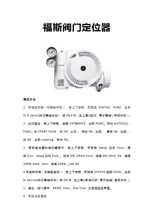
福斯阀门定位器调试方法1、手自动切换(切换到手动),按上下按钮,然后按STATUS,FUNC,出现O O serric(执行离线状态),按OK3秒,左上角□在闪,表示离线(手动状态)。
2、自动整定,按上下按钮,选择CATIBRATE,出现FUNC。
再按AUTOCAL,FUNC。
按START TUNE,按OK,出现…,再按OK,出现…,再按OK,出现…,按OK,出现rotating,再按OK。
3、修改电流值和定位器显示,按上下按钮,然后按Setup回到Func,再按Curr range回到Func。
选择0%-20mA Func 选择0%-0mA Ok 选择100%-4mA func 选择100%-_mA OK4.手自动切换(切换到自动),按上下按钮,然后按STATUS回到FUNC,出现In serrice(执行离线状态),按OK秒,左上角□取消闪动,表示在线(自动状态)。
5、退出,按↑↓调节,REND Func,Pos Func 之后返回主界面。
6、手动点动调试首先将调校DIP开关拨到Jog位置,用户只能手动设置满量程,不能设置全关位,阀门全关位为默认状态。
当DIP 开关拨到Jog位置时,定位器的二极管的状态为黄-红-红-绿。
此时用户再用Jog按钮↑↓手动调节阀门至所期望的100%,阀门到位后,同时按↑和↓按钮,这时阀门自动进行调整,等调整结束后二极管的状态回到黄-红-红-绿,再重新进行100%的设定,设定完成后,同时按↑和↓按钮,阀门进行自动调整。
调整完毕后,二极管的状态以绿色开始。
这表明手动调试完成,定位器正常。
7、就地手动操作QUICK-CAL按钮和↑和↓三个按钮同时按住三妙钟,二极管的状态黄-绿-红-红,此时松开三个按钮,就可以用↑和↓进行阀门开关操作。
按QUICK-CAL按钮即可退出手动操作,恢复自动状态。
福斯FLOWSERVE阀门定位器

福斯FLOWSERVE阀门定位器福斯定位器配置指南福斯(FLOWSERVE)阀门定位器调试方法(锦菲特I3599429OO2)[Q-Q,6696 22933]flowserve阀门、Flowserve 3400IQ定位器、LOGIX500、LOGIX510、LOGIX520、D3系列P-5 气动定位器电动气动数字 - 通用,IS 和 EXHART、Profibus、Foundation 现场总线反馈机组、限位开关比如 PP5XX-HPGU-23K01-PV9DA-3ZPMV P-1700 系列阀门专为腐蚀或高温环境应用设计,其所有外部零件均由不锈钢制造而成。
P-1700 和 1720 型阀门的内部零件采用不锈钢制造,而P-1710 和 P-1730 型阀门的内部零件则采用铝制。
P-1720 和P-1730 型阀门具有超高的空气传送能力。
P-1700 系列阀门专为双向操作应用设计,不过也可通过旋动一个阀座轻松实现单向操作。
不锈钢磁场外壳内的PMV I/P转换器很容易安装在 P-1700 系列阀门上。
P-1500 P-1520P-1700 P-1720P-1710 P-1730Digital具有 PID 控制的2000 数字定位器品牌 Logix说明福斯 Logix 2000 是一款具有板载 PID 控制的数字定位器。
通信方式为 4-20mA 或Modbus。
阀门上安装的 PID 控制器每秒更新阀杆次,从而减少了控制系统延迟。
Logix3200IQ 数字定位器 3200IQ-10-D6-M-04-40-0G-0F3200IQ-10-D6-M-04-40-0G-00品牌 Logix说明福斯 Logix 3200IQ 数字 HART? 定位器使用先进的 piezo 技术提供一流的性能和可靠性。
通过使用本地按钮、HART 手持设备和SoftTools软件可轻松配置 Logix 3200IQ。
LOGIX 3201IQ定位器 P/N:215809.999.000,SN:4107028LOGIX 3202IQ定位器 P/N:221734.999.000,SN:4907010LOGIX 3203IQ定位器 P/N:216428.999.000,SN:610727定位器 P/N:215809.999.000,SN:55070043400IQ Digital Positioner品牌 Logix说明 The Flowserve Logix 3400 Series digital Foundation? Fieldbuspositioner utilizes state-of-the-art piezo technology to provide…500 数字定位器品牌 Logix说明福斯 Logix 500 数字定位器是下一代本质安全型 Logix 500 系列的代表。
福斯Logix520si定位器说明书
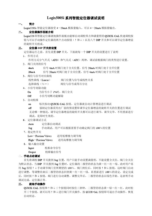
Logix500Si系列智能定位器调试说明一、简介Logix520Si智能定位器接受4-20mA模拟量输入,可以4-20mA模拟量输出。
二、定位器操作面板介绍Logix520四智能定位器就地操作面板由能够自动调校零点和满量程的QUICK-CAL快速调校按钮与可以手动操作定位器的两个点动按钮(↑和↓)以及八个DIP开关和可以调节定位器增益的旋转开关组成。
三、定位器DIP开关的设置定位器运行之前,首先设置DIP开关,下面就每一个DIP开关的设置进行了说明1、作用方式作用方式分气开式(ATO)和气关式(A TC)两种,调试前根据阀门的类型进行设置。
2、阀门关闭的信号4mA 信号4mA时阀门处于全关位置,信号20mA时阀门处于全开位置20mA 信号20mA时阀门处于全关位置,信号4mA时阀门处于全开位置3、阀位与信号对应曲线线性曲线(Linear)阀门位置与信号成线性关系选择曲线(%=)阀位与信号成等百分比4、小信号切除功能On 当信号小于1%时,阀门全关Off 小信号切断功能解除5、自动校准on 每次按动QUICK-CAL按钮,定位器就自动计算增益进行调试off 强制定位器采用出厂前的预设置即调节定位器增益的旋转开关的位置进行调试无论哪一种情况,调节定位器增益的旋转开关都可以进行调节,调节完毕,不用重新进行调试,是即时生效的。
6、定位器调试方式Auto 定位器自动调试Jog 手动调试,用户可以根据需要手动确定阀门的100%的位置7、稳定性开关Low-Friction Valves 适用低摩擦力调节阀High-Friction Valves 适用高摩擦力调节阀8、输入输出设置Input 校准命令信号Output 校准输出信号二、手动点动调试首先将调校DIP开关拨到Jog位置,用户只能手动设置满量程,不能设置全关位,阀门全关位为默认状态。
当DIP 开关拨到Jog位置时,定位器的二极管的状态为黄-红-红-绿。
福斯3200IQ说明书 中文版

福斯3200I Q说明书中文版-CAL-FENGHAI.-(YICAI)-Company One1Logix3200IQ智能定位器调试说明一、简介Logix3200IQ智能定位器接受4-20mA模拟量输入,4-20mA模拟量输出。
二、定位器操作面板介绍Logix3200IQ智能定位器就地操作面板由能够自动调校零点和满量程的QUICK-CAL快速调校按钮与可以手动操作定位器的两个点动按钮(↑和↓)以及八个DIP 开关和可以调节定位器增益的旋转开关组成。
三、定位器DIP开关的设置定位器运行之前,首先设置DIP开关,下面就每一个DIP开关的设置进行了说明1、作用方式作用方式分气开式(A TO)和气关式(A TC)两种,调试前根据阀门的类型进行设置。
2、阀门关闭的信号4mA 信号4mA时阀门处于全关位置,信号20mA时阀门处于全开位置20mA 信号20mA时阀门处于全关位置,信号4mA时阀门处于全开位置3、阀位与信号对应曲线线性曲线(Linear)阀门位置与信号成线性关系选择曲线(Optional)选择了这个按钮,就激活了下一个DIP开关4、可选择曲线%=阀位与信号成等百分比Custom 用户自定义曲线5、自动校准on 每次按动QUICK-CAL按钮,定位器就自动调整参数进行调试off 每次调试时,只能根据出厂前的预设置即调节定位器增益的旋转开关的位置进行调试无论哪一种情况,调节定位器增益的旋转开关都可以进行调节,调节完毕,不用重新进行调试,是即时生效的。
6、稳定性开关Low-Friction V alves 适用低摩擦力调节阀High-Friction V alves 适用高摩擦力调节阀7、备用开关8、定位器调试方式Auto 定位器自动调试Jog 手动调试,用户可以根据需要手动确定阀门的100%的位置二、手动点动调试首先将调校DIP开关拨到Jog位置,用户只能手动设置满量程,不能设置全关位,阀门全关位为默认状态。
FISHER定位器调试说明书
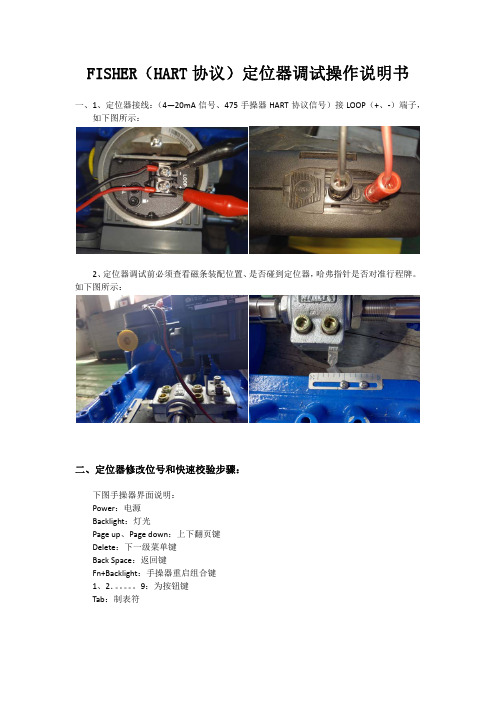
FISHER(HART协议)定位器调试操作说明书一、1、定位器接线:(4—20mA信号、475手操器HART协议信号)接LOOP(+、‐)端子,如下图所示:2、定位器调试前必须查看磁条装配位置、是否碰到定位器,哈弗指针是否对准行程牌。
如下图所示:二、定位器修改位号和快速校验步骤:下图手操器界面说明:Power:电源Backlight:灯光Page up、Page down:上下翻页键Delete:下一级菜单键Back Space:返回键Fn+Backlight:手操器重启组合键1、2.。
9:为按钮键Tab:制表符1、按电源键打开475手操器,按Enter键点击HART图标后将进入下一步,如下图所示:2、按下键选择Online(使手操器处于在线模式)图标后按右键进入下一步,如下图所示:3、按下键选择Configure(配置)图标后按右键进入下一步,如下图所示:4、按下键选择Manual Setup(手动设置、相当于参数设置)图标后按右键进入下一步,如下图所示:5、按下键选择lnstrument(设备)图标后按右键进入下一步,如下图所示:(这一步是更改位号)6、按下键选择ldentification(识别)图标后按右键进入下一步,如下图所示:7、根据指示单位号进行修改,修改完成后按ENTER键,如下图所示:8、修改完HART Tag(位号)后,HART Tag(位号)图标前会出现*型标记,这时按SEND 键进行发送保存位号,如下图所示:9、修改完位号后,按左键返回到Manual Setup(手动设置、相当于参数设置)图标下,然后按下键到Calibration(校验)图标下后按右键进入下一步,如下图所示:(这一步开始快速整定定位器)10、选择Travel Calibration(行程校验)图标后按右键进入下一步,如下图所示:11、按下键选择Auto Calibration(自动校验)图标后按右键进入下一步,如下图所示:12、更改定位器模式(In Service(投用模式)、Out of Service(非投用模式)),按下键选择Out of Service(非投用模式),然后按ENTER键,进入下一步,如下图所示:定位器整定过程中,模式必须更改为Out of Service(非投用模式)手操器上显示的这句话意思:(警告:当模式更改为Out of Service(非投用模式)时,定位器的输出将不受输入信号控制)13、选择Continue(继续)图标后按ENTER键进入下一步,如下图所示:手操器上显示的这句话意思:(警告:设备的输出在校验过程中将发生改变)14、定位器开始整定(寻找阀门行程最高点、最低点、中间点、定位器开始模块运算和优化)如下图所示:15、自动校验完成后按OK键,然后把定位器模式改回In Service(投用模式),如下图所示:整定完成后必须把模式更改回In Service(投用模式),不然中控给定输入信号后,阀门将不动作。
定位器操作说明

(三)注意事项
• 压缩空气气源要保持洁净,干燥 • 电气接口接线后密封可靠,无松动 • 定位器调试完成后,外壳盖紧 • 如果个别位置无法排除外界杂质进入定位
内部,可参考做如下图处理
谢谢!
A. 基础菜单与完整菜单之间的切换 基础菜单(basic menu)只有 5 项,完整菜单 (full menu)有 9 项。在 shift menu 里面完 成基础与完整菜单之间的切换。
B. 切换中文菜单 出厂默认是英文菜单,可以在设定(setup) 里面找到外观(Appearance),再找到语言 (language),从中选择中文(chinese)。 按 OK 键确认选择。界面瞬时换成中文。
自动调试
• 首先切换到离线状态,此时屏幕左上角有竖条光标在闪烁,
表示定位器处于已处于离线状态,此时不接受 DCS 信号 控制。同时按住上,下两键 5 秒钟,此时三个灯交替闪烁, 松手,此时已开始自动校验。校验结束会停留在黄灯闪烁 (阀门处于开或者关的位置)或者绿灯闪烁(阀门处于中 间位置)。
• 或者进入校验(calibrate)菜单,选择自动校验(
• 方法如下: • 依次输入4,8,12,16,20mA,检查阀门位置是否一
一对应,连续按3次黄色按键,此时正反作用已切 换,重新输入4,8,12,16,20mA检验。
恢复出厂设置
• 在断电(也就是不接入信号)情况下,按 住黄色按钮,然后按照正负极接入信号 (直到三个灯被点亮,然后黄-红交替闪 烁),此时松开按钮,这时就完成了恢复 出厂设置。
4-20mA 输出信号校验
• 进入校验(calibrate)菜单,选择专业校验 (expert cal),进入传送(transm)。校 验传送低值(transm low)调整到 4mA 按 OK 键确认;校验传送高值(transm hi)调 整到 20mA 按 OK键确认。前提是需要给输 入接线柱 4mA 供电,同时输出接线柱串联 24V 电源和万用表测量输出。
福斯定位器配置指南

福斯定位器配置指南福斯(FLOWSERVE)阀门定位器调试方法(锦菲特I3599429OO2)[Q-Q,6696 22933]flowserve阀门、Flowserve 3400IQ定位器、LOGIX500、LOGIX510、LOGIX520、D3系列P-5 气动定位器电动气动数字- 通用,IS 和EXHART、Profibus、Foundation 现场总线反馈机组、限位开关比如PP5XX-HPGU-23K01-PV9DA-3ZPMV P-1700 系列阀门专为腐蚀或高温环境应用设计,其所有外部零件均由不锈钢制造而成。
P-1700 和1720 型阀门的内部零件采用不锈钢制造,而P-1710 和P-1730 型阀门的内部零件则采用铝制。
P-1720 和P-1730 型阀门具有超高的空气传送能力。
P-1700 系列阀门专为双向操作应用设计,不过也可通过旋动一个阀座轻松实现单向操作。
不锈钢磁场外壳内的PMV I/P 转换器很容易安装在P-1700 系列阀门上。
P-1500 P-1520P-1700 P-1720P-1710 P-1730Digital具有PID 控制的2000 数字定位器品牌Logix说明福斯Logix 2000 是一款具有板载PID 控制的数字定位器。
通信方式为4-20mA 或Modbus。
阀门上安装的PID 控制器每秒更新阀杆位置16 次,从而减少了控制系统延迟。
Logix3200IQ 数字定位器3200IQ-10-D6-M-04-40-0G-0F3200IQ-10-D6-M-04-40-0G-00品牌Logix说明福斯Logix 3200IQ 数字HART? 定位器使用先进的piezo 技术提供一流的性能和可靠性。
通过使用本地按钮、HART 手持设备和SoftTools软件可轻松配置Logix 3200IQ。
LOGIX 3201IQ定位器P/N:215809.999.000,SN:4107028LOGIX 3202IQ定位器P/N:221734.999.000,SN:4907010LOGIX 3203IQ定位器P/N:216428.999.000,SN:610727定位器P/N:215809.999.000,SN:55070043400IQ Digital Positioner品牌Logix说明The Flowserve Logix 3400 Series digital Foundation? Fieldbuspositioner utilizes state-of-the-art piezo technology to provide…500 数字定位器品牌Logix说明福斯Logix 500 数字定位器是下一代本质安全型Logix 500 系列的代表。
logix520福斯定位器说明书

Logix 520MD系列数字定位器FCD LGENIM0520-00用户指导说明书安装操作维护实践中积累经验目录页码基本信息............................................................................................. 2 拆箱..................................................................................................... 3 Logix 520MD 概要............................................................................... 4 技术参数............................................................................................. 4 工作原理............................................................................................. 5 气路连接.............................................................................................. 6 接线..................................................................................................... 6 电缆要求.............................................................................................. 7 调试..................................................................................................... 8 Logix 520MD 就地界面操作............................................................ 8 配置Dip 开关设置的操作................................................................ 8 校准开关........................................................................................ 9 快速校准操作................................................................................. 9 恢复出厂设置................................................................................. 10 4-20 mA 模拟输出板....................................................................... 10 错误代码.............................................................................................. 12 故障排除.............................................................................................. 15 限位开关............................................................................................. 16 备件包................................................................................................. 17 尺寸图. (18)1 正确使用福斯阀门福斯阀门、、执行执行器和附件器和附件 1.1手册手册使用使用使用说明说明以下指导说明用于帮助对福斯产品进行拆箱、安装和性能维护。
美国福斯Valtek Star Pac II基地式仪表控制系统及2000系列数字阀门定位器用户手册

GENERAL INFORMATIONThe following instructions are designed to assist in unpacking, installing and performing maintenance as required on Valtek® StarPac® II Intelligent Control Systems and Logix TM 2000 Digital Positioners. Product users and maintenance personnel should thoroughly review this bulletin prior to installing, operating, or performing any maintenance on the valve.More detailed operation instructions are included in the StarPac II / Logix 2000 Manual; refer to them when more information is needed.Separate Valtek Installation, Operation, Maintenance instructions cover the valve (IOM 1 or IOM 27) and actuator (IOM 2 or IOM 31) portions of the system and other accessories. Refer to the appropriate instructions when this information is needed.To avoid possible injury to personnel or dam-age to valve parts, users must strictly adhere to WARNING and CAUTION notes. Modifying this product, substituting non-factory parts, or inferior parts, or using maintenance proce-dures other than outlined could drastically affect performance and be hazardous to per-sonnel and equipment, and may void existing warranties.WARNING: Standard industry safety practices must be adhered to when working on this, or any, process control product. Specifically, personal protective and lifting devices must be used as warranted. Unpacking1.While unpacking the StarPac II / Logix 2000 unit,check the packing list against the materials re-ceived. Lists describing the system and accesso-ries are included in each shipping container.2.When lifting the system from the shipping container,position lifting straps to avoid damage to tubing and mounted accessories. Systems with valves up to eight inches may be lifted by actuator lifting ring. On larger systems, lift unit using lifting straps or hooks through the yoke legs and outer end of body.WARNING: When lifting a valve/actuator as-sembly with lifting straps, be aware the center of gravity may be above the lifting point. There-fore, support must be given to prevent the valve/actuator from rotating. Failure to do so can cause serious injury to personnel or dam-age to nearby equipment.3.In the event of shipping damage, contact yourshipper immediately.4.Should any problem arise, contact your ValtekControl Valve representative.Valtek StarPac II Intelligent Control System Valtek Logix Series 2000 Digital PositionerTools required for StarPac II / Logix 2000 Maintenance and Start-up1.Multi-meter w/alligator clips, probes & jumpers2.4-20 mA analog calibrator with power supply3.RS-232-485 communication and cabling4.Windows TM compatible PC5.Standard 6-inch flat screwdriver6.Standard phillips screwdriver7.1/4-inch flat screwdriver8.Small wire cutter (flush cut) & wire strippers9.Needle-nose pliers10.1/16-inch allen wrench11.Vise grips12.Small vise grips13.1/2-inch nut driver14.5/32-inch allen wrenchrge crescent wrench (minimum 15-inch)16.8-inch channel lock pliers17.3/32-inch screwdriver18.Wrist grounding strap19.Antistatic bag or packaging20.EPROM remover (PLCC type)21.Electrical tape22.Feedback shaft tool and drive modulepressure calibration connectors (suppliedwith feedback module kit)If the StarPac II is being installed in an insulated process line, do not place more than four inches of insulation around the pressure or temperature sensors; otherwise the sensors may not operate properly. In addition, NEVER insulate the unit electronics assembly or remote-mounted temperature/pressure sensors (when used).CAUTION: Do not insulate the StarPac II / Logix 2000 electronics housing or remote-mounted pres-sure or temperature sensors; otherwise excessive heat may build up and affect operation.Wiring and Grounding GuidelinesThis section will help you achieve a maximum “noise -free”environment and performance with a StarPac II / Logix 2000 unit.Shielding Versus GroundingAll signals to the StarPac II / Logix 2000 unit should be in shielded cables. Shields must be tied to a ground at only one end of the cable to provide a place for environ-mental electrical noise to be removed from the cable. A ground wire (unlike a shield) is attached at both ends to provide a continuous path for electrical conductivity. Grounding ScrewThe green grounding screw by the user interface termi-nal block should be used to provide the unit with an adequate and reliable earth ground reference. This ground should be tied to the same ground as the electrical conduit. Additionally, the electrical conduit connecting to the unit should be earth grounded at both ends of its run. The green grounding screw must not be used to terminate signal shield wires.24VDC PowerThe 24 VDC connection points will work best with shielded twisted pair wire with the shield wire connectedINSTALLATIONValve InstallationThe StarPac II / Logix 2000 Intelligent Control System valve is installed in the same manner as a conventional control valve and according to industry standards. Refer to the appropriate valve installation, operation, mainte-nance instructions for proper installation procedures.Electronics Module with Keypad and Local DisplayAir Lines toCylinder ActuatorUser Access Terminal BehindLower DoorTemperature SensorProcess Pressure SensorsElectronics ConduitPosition Feedback ArmFigure 2: StarPac II / Logix 2000 Intelligent Control System Componentsonly at the source. The input power is isolated within the unit and may be referenced to whatever level is neces-sary. The 24 VDC power supply should not be connected to earth ground.RS-485 CommunicationRS-485 wiring requires the use of a shielded twisted pair cable, which is grounded only at the source and not in the unit. (For maximum performance, wire should have a characteristic impedance of 120 ohms.) The RS-485 input is fully isolated, using opto-isolators.The RS-485 allows only a 7 to 12 V common mode voltage differential between stations. Valtek's RS-232to RS-485 converter is not a grounded connection.PC's with internal RS-485 cards, on the other hand, are often grounded. If another ground communication device is on the network, a fault condition will almost certainly exist due to transient and steady state differ-ences in ground potential.4 - 20 mA Command Input, Auxiliary Input, and Feedback OutputThese signals are isolated but shielded twisted pair wire should be used to reduce crosstalk from other signals.The shield should be connected only at the source.Discrete Inputs and OutputsThese signals are isolated, but because they are fre-quently used to switch high voltage (120 VAC), they should be run in separate shielded wire paths away from the other StarPac II / Logix 2000 signals.AIB and RS-232 to RS-485 Converter Connection When connecting a StarPac II / Logix 2000 unit to a communication device, no shield or ground connec-tions exist. Hence, the 24 VDC power and RS-485communication shield drain wires must be connected to a convenient ground near the AIB or converter.Wiring The StarPac II / Logix 2000 SystemAll electrical connections must be done according to local and industry electrical codes. Valtek recommends a shielded cable be used for the RS-485 command signal wire (e.g., Belden 9841 or equivalent).When connecting multiple StarPac II / Logix 2000 units,a parallel daisy-chain wiring pattern is used. Connect unit's branch lines to main line, keeping branch lines as short as possible. The total length of wiring should not exceed 4,000 feet (1,200 meters) without use of repeaters.Avoid devices producing electrical 'noise' while install-ing the cable.CAUTION: The following procedure should be per-formed on the bench or with the unit isolated so that unexpected valve stroking will not adversely affect the process.WARNING: The following procedures may cause the valve to stroke, causing pressures and tem-peratures to vary from their norms. Notify appropri-ate personnel that the valve may stroke unexpect-edly. Valtek suggests that the system be isolated from the process, if installed in line.Figure 3: Exploded View44.Regulator set screw45.Regulator housing screw (4)46.Regulator housing 47.Spring button 48.Regulator spring49.Regulator diaphragmassembly50.Driver module mountingscrew (4)51.Pilot valve52.Pilot valve screw (4)53.Pilot valve gasket 54.Regulator filter 55.Poppet guide 56.Poppet O-ring 57.Poppet1.Upper door assembly2.Door screw (4)3.Upper door gasket4.Lower door assembly5.Door screw (2)6.Lower door gasket7.Inner door/keypad assembly 8.Inner door screw (4)9.Feedback cover assembly 10.Cover screw (4)11.Driver cover assembly 12.Cover screw (4)13.Hydrophobic filter cover 14.Cover screw (2)15.Hydrophobic filter16.Hall potentiometer assembly 17.Potentiometer bracket 18.Flex couple19.Bracket screws (2)20.Torsional spring 21.Feedback shaft 22.Shaft O-ring 23.Retaining ring 24.Screw, hard stop25.Feedthrough assembly 26.Feedthrough O-ring 27.Board screw (2)28.Block screw (2)29.Isolator (4)30.Filter (2)31.Adapter O-ring, lower (2)32.Pressure sensor adapter 33.Adapter O-ring, upper (2)34.StarPac II / Logix 2000board assembly 35.Board stiffener36.Board assembly screw (3)37.Board stiffener screw38.Board assembly screw (3)39.Board assembly screw 40.Personality card41.Personality card screw (4)42.Rubber grommet (2)43.Housing assembly58.Poppet spring 59.Spool 60.Spool clip61.Driver manifold O-ring 62.Driver spacer 63.Driver bearing64.Spool return spring 65.Driver piston 66.Magnet67.Driver manifold diaphragm 68.T-board screw (2)69.T-board70.Orifice screw71.Orifice screw O-ring 72.Orifice O-ring 73.Testing plug (2)74.Coil O-ring75.Pressure modulatorassembly76.Spring diaphragm 77.Modulator cover 78.Modulator set screw 79.Modulator screw (3)80.Inner door screw (2)81.Inner door screw O-ring (2)82.Keypad gasket 83.Wire harness84.24-pin ribbon cable 85.14-pin ribbon cable85848361428278180797877767574737271706968676665646362605958575655545352515049484746454443413435373638403933323130292827262510161924232122201817151413121198654321P 1 G r n d (B l k )P 2 G r n d (B l k )P 1 o u t - (W h t )P 2 o u t - (W h t )P 1 o u t + (G r n )P 2 o u t + (G r n )P 1 +5 V D C (R e d )P 2 +5 V D C (R e d )T h r m C o u p (Y e l )A n a l o g 2i n -T h r m C o u p (R e d )A n a l o g 2i n +A n a l o g 2 o u t -A n a l o g 1 i n -A n a l o g 2 o u t +A n a l o g 1i n +A n a l o g 1 o u t -S p a r eA n a l o g 1 o u t +P u l s e O u tS p a r eP u l s e O u tC o m B -A l a r m C o n t a c tC o m B +A l a r m C o n t a c tC o m A -D i s c r e t e 2 i nC o m A +D i s c r e t e 2 i n24 V D C -D i s c r e t e 1 i n24 V D C +D i s c r e t e 1 i nC o m A +C o m A -12345678910111213141516171819202122232425262728293031323334Figure 4: User Interface Terminal Pinouts•Ensure that the block valves in the process line around the unit are closed and the process is diverted around the unit.T able I:User Interface T erminal ConnectionsSignalNegative Positive Term. No.Term. No.24 VDC power1617Valve command signal 2425Primary RS-4851415communication link Secondary RS-4851213communication link Auxiliary input (4-20 mA)2223Analog output (4-20 mA) 1910Analog output (4-20 mA) 278Discrete input 1– switch/3334solenoid monitoring (discrete mode source input)Discrete input 2 – switch/3132solenoid monitoringDiscrete output 1 (malfunc-2930tion alarm contact)Discrete output 2 (pulse)27283.Turn on the 24 VDC power to the unit, and verify that it has been correctly wired by checking the following:•24 VDC power is at least 300 mA and between 18.0and 64.0 VDC •Polarity is correct•Local display is on; if not, check the power supply.4.Close the front cover on the housing of the unit.To connect the wiring to the StarPac II / Logix 2000 unit,refer to Figures 1 and 4, and Table I, then proceed as follows.1.Open the lower door on the front of the housing.WARNING: Do not open the electronic housing covers in flammable atmospheres; otherwise,possible injury to personnel or equipment may occur.2.Connect the required wires to the terminal interface block and computer as described in Figure 4 and Table I. (The system must have 24 VDC power for operation.)NOTE : The StarPac II / Logix 2000 unit remembers the operating mode setting (automatic or manual)from the last time the unit had power. When power to the system is turned on again, the unit will resume operation in the previous mode.Normally the unit arrives from the factory set in the manual analog operating mode. This means a command signal will position the valve the same as a traditional control valve, providing a plug position proportional to the 4 - 20 mA signal.To avoid upsetting the process because of improper operating mode selection:•Ensure that the system arrived from factory with the proper operating mode setting in the shop prior to installation by connecting air supply and com-mand signal, then turning on the power and looking at the mode value on the local display, or;•Set the proper operating mode for the particular application in the shop prior to installation by selecting the desired operating mode from the local interface or in the Tuning/Tune screen of the StarTalk software, or;Termination JumpersSystem Communication Default ConfigurationStarPac II / Logix 2000 units are shipped from the factory ready for installation and operation. Rarely do the units need to be re-configured prior to operation. Table II lists the factory default communication settings. If these settings are not correct for the equipment being used,proceed to the following sections.Table II: Factory Default Mode SettingsDescription Setting Address 1Parity odd Baud Rate19,200Modbus Communication Mode RTU RS-485 Termination ResistorsInstalledSelecting Correct Address SettingIf the StarPac II / Logix 2000 unit is the only one on the communication network, the default address (1) is fine.If multiple units will be operating on the same communi-cation network, each unit must have a unique address.Before changing the address, the StarTalk software can be used to determine what devices are on the line.(Remember to include devices that may be temporarily off line.)If the default address setting needs to be changed, use the 'Comm' option in the configuration menu of the local interface to change the settings.Selecting Correct Baud Rate SettingStarPac II / Logix 2000 units support baud rates of up to 57,600 baud. However, both the StarPac II / Logix 2000system and StarTalk software are shipped from the factory set to 19,200 baud.If the default baud rate setting needs to be changed, use the 'Comm' option in the configuration menu of the local interface to change the settings.Selecting Correct Modbus Transmission ModeTwo transmission modes exist in a Modbus system,ASCII and RTU (default). Use the ASCII mode when transmitting information through a device that uses ASCII control codes; for example, a modem. Use the RTU mode when connecting directly to both devices; for example, an RS-485 interface card wired directly to a StarPac II / Logix 2000 system.If the default Modbus transmission mode setting needs to be changed, use the 'Comm' option in the configura-tion menu of the local interface to change the settings.Selecting Proper RS-485 Termination Resistor SettingA termination resistor must be installed on the two most remote devices on the network, counting the host computer as any other device.(For example, a single StarPac II / Logix 2000 unit and the RS-485 driver in the host computer would each require the termination resistor to be installed. If four units were on the network with a host computer, decide which of the two devices have the most combined cable length between them. These two devices should have the termination resistors installed. The termination resistors should be disabled in the devices not consid-ered to be the most remote using the instructions in the next section. Using more than two termination resistors in a network can cause the RS-485 communications to operate erratically or fail.)To enable 120 ohms termination, insert both jumpers for A and B channels. To disable termination, remove both jumpers from each channel as shown in Figure 5.SYSTEM MAINTENANCEValtek recommends that the StarPac II / Logix 2000system calibration be checked every six months. If,after checking the unit, a component is determined to be defective, the following section will help with the component replacement.The following items may be needed to install, start up and calibrate the unit's electronics.Figure 5: Termination Jumpers andPersonality Module•Power supply: 24 VDC, 300 mA•Digital volt meter with 4 - 20 mA range•Air supply: 50 psig minimum, 80-100 psig preferred •Gauges or the ability to accurately determine pro-cess pressures and valve air supply pressures•4 - 20 mA command source•Thermocouple calibrator or simulator with 0 to 500°Celsius rangeMechanical Subsystem MaintenanceRefer to the appropriate Valtek Installation, Operation & Maintenance (IOM) instructions for details on repair and maintenance of the control valve actuator components. Please refer to the manufacturers’ manuals for mainte-nance and operation instructions for non-pneumatic actuators, e.g., electric or electro-hydraulic actuators. WARNING: The process line must be depressurized and drained of process fluid and decontaminated prior to working on internal valve components. Fail-ure to do so may cause serious injury to personnel.1.Depressurize the line, decontaminate the valve (ifneeded) and shut off the air supply to the valve positioner.2.Disconnect the actuator air tubes from the unit.3.Disconnect the two mounting bolts that attach theStarPac II / Logix 2000 system bracket.4.Disconnect the follower arm from the unit base.This is done by removing the follower arm nut and washer and pulling the arm off the shaft. Notice that this shaft connection is keyed and that the shafts are slightly spring loaded.5.The actuator subassembly is now isolated and isremoved by loosening the bonnet bolts and lifting the actuator away from the body.The tubing holds the StarPac II / Logix 2000 base in place, eliminating the need to disconnect wiring or air connections.6.Standard valve maintenance may now be done onthe actuator or valve body components. Refer to the Valtek IOM instructions for details on such things as trim or packing replacement. If you have to replace the trim, use the same trim number and characteristic as the original trim so the flow calcu-lations are not affected. If a trim size change is needed, contact your Valtek representative to find out about flow characterization options.7.Reassemble the system by reversing the abovesteps. Be sure to follow the procedures outlined in the Valtek IOM instructions for valve reassembly.When reconnecting the follower arm, make sure that the arm fits correctly on the keyed shaft and hasa positive spring action.8.Turn on the air supply to the valve and check forleaks in the reattached actuator tubing lines.9.Turn on power to the unit. Check the systemcalibration and perform a Valve Stroke Calibration to reset the position feedback. Refer to the Calibra-tion section of the StarPac II / Logix 2000 manual. StarPac II / Logix 2000 Positioner OverviewThe StarPac II / Logix 2000 is double-acting, capable of supplying air to either side of the actuator piston while exhausting the other side to the atmosphere. Also, the positioner can be mounted on either Valtek linear or rotary actuators without modification to the actuator. The positioner is pending non-incendive for class I, division II, groups A, B, C, and D; class II, groups E, F, and G. Since the positioner is insensitive to supply pressure changes and can handle supply pressures from 30 to 150 psig, a supply regulator is usually not required; however, an air filter is required due to the close tolerances of the spool assembly.NOTE: The air supply should conform to ISA Standard S7.3 (a dew point at least 18° F below ambient temperature, particle size below 5 microns, oil content not to exceed 1 part per million). Positioner OperationThe StarPac II / Logix 2000 Positioner is an electric feedback instrument. Figure 6 shows a StarPac II installed on a double-acting actuator for air-to-open action. Positioning is based on a balance of two signals: one proportional to the modulator input signal and the other proportional to the stem position.The supply pressure for the positioner modulator is tapped off the main supply and is filtered as it passes through a field-replaceable, coalescing filter element in the module. Next it passes through an internal pressure regulator that regulates it to approximately 22 psig. The air then goes through an orifice that restricts the flow and air consumption (refer to Figure 6).The air is further controlled to 6-12 psig using a spring-diaphragm flapper that is attracted by an electromagnet to a nozzle. A temperature compensated hall effect sensor mounted on a circuit board senses the spool valve position. The hall effect sensor and circuitry create a feedback loop, which determines how much current to send to the electromagnet for a desired spool valve position. The electromagnet in the feedback loop varies the nozzle-flapper spacing, which regulates the output pressure to 6-12 psig proportional to the com-mand input signal.When these opposing signals are equal, the system will be in equilibrium and the stem will be in the position called for by the command signal. If these opposingPosition Feedback SystemThe position feedback linkage of the StarPac II / Logix 2000 system is a critical part of the system. This linkage is also used in the StarPac II to calculate the valve ’s C V for a given stroke for flow measurement. This linkage should be lubricated and checked periodically for tight,smooth operation. The follower arm should operate smoothly with no binding and have a positive spring loading on the arm. Inspect the follower arm pin for excess wear and replace if needed. The take-off arm attached to the stem clamp must be firmly secured to the stem clamp and perpendicular to the actuator stem.If this takeoff arm is canted or misaligned, problems may occur with positioner calibration and the position reading on the unit may go out of range.On rotary actuators, make sure the adjustment linkage locknut is tight and has no excessive play in the ball joints. The rotary shaft clamp must be tight and should not freely rotate on the shaft.Pressure Sensor ReplacementStandard StarPac II pressure sensors are typically in-stalled directly into the control valve body. Before they can be removed, the process line must be depressurized and drained of all fluids and the valve decontaminated.To replace a pressure sensor, refer to Figure 7 then proceed as follows.WARNING: The process line must be depressurized and drained of process fluid, and decontaminated prior to working on internal valve components. Failure to do so may cause serious injury to personnel.Figure 6: Positioner Diagramsignals are not equal, the spool valve will move up (or down) and, by means of the modulator, will change the output pressures and flow rate. This will cause the piston to move until the signal of the feedback sensor equalizes with the command signal.The detailed sequence of positioner operations are as follows: An increase in the command signal forces the modulator signal capsule and spool valve upward. This motion of the modulator also pushes the pilot valve spool upward from its equilibrium position. This opens the pilot valve ports, supplying air to port one and exhausting air from port two. This causes the actuator piston to move upward.This upward motion of the piston is transmitted back to the positioner through the feedback linkage and hallpot sensor signal changing proportionally to the valve posi-tion. The piston continues to stroke upward until the signal of the feedback sensor increases sufficiently to counter the signal being sent to the modulator. At this point, the spool is at its equilibrium position as the pressures in the cylinder stabilize and the air flow to the actuator decreases.After the piston has reached the required position, the feedback signal will equal the spool position generated in the modulator capsule. The computer will then make small null adjustments to fine-tune the desired position and compensate for changes in dynamic loading.A decrease in the command signal reverses the de-scribed actions causing a proportional downward move-ment of the actuator piston and stem.7.Align the red dots on the sensor and connector,and reconnect the Lemo connector. Fully seat the connector until the locking sleeve latches. Replace the sensor nut and tighten. 8.Pressurize the valve body to make sure the sensorsare properly seated before attaching the sensor conduit and tightening. 9.Reattach the conduit lines and securely tighten thefittings.Figure 8: Thermocouple Replacement Thermocouple ReplacementIn normal configuration, the thermocouple does not penetrate the valve body wall. Depressurizing the body is not necessary when replacing the thermocouple.NOTE: If the StarPac II was ordered with a special thermocouple option, verify the need to depressurize the body before proceeding.1.Disconnect power and air supply to the unit.2.Open the lower terminal block cover and discon-nect the red and yellow thermocouple wire.3.Loosen the tubing nuts on both ends of the thermo-couple assembly (refer to Figure 8).4.Pull the wires out of the StarPac base and slip the tubing off the wires.5.Unscrew the old thermocouple from the body.6.Install the new thermocouple.7.Feed the wires back through the tubing and into the StarPac housing.8.Tighten the tubing nuts.9.Cut the thermocouple wires to length. Strip and reattach wires to the terminal block, noting color polarity. (The red wire is the negative signal.)10.Check that all the fittings are tight.Figure 7: Disconnecting Lemo ConnectorWARNING: If the pressure sensors are remote-mounted, the sensor will be located in a sensor housing in the tubing line and not in the sensor housing located on the valve body. This section of the tubing contains process fluid and must be drained and decontaminated before the sensor is removed. The procedure for sensor removal and replacement will be similar to that outlined below.(Refer to alternate sensor information when this type of sensor is included with system.)1.Depressurize and decontaminate the line and valve.Loosen the tubing nuts on the conduit leading to the pressure sensor, if applicable.2.Loosen the sensor nut.3.Gently pull the conduit and sensor nut approxi-mately 1/2 to 0.75-inch from the sensor. Use needle nose pliers to release the locking sleeve of the Lemo ™ connector by moving the collar away from the sensor and disconnect the connector from the sensor. Swing the sensor conduit out of the way (refer to Figure 7).4.Unscrew the sensor from the sensor boss.5.Remove the sensor O-ring or gasket and replace with a new one. Make sure the environmental O-ring seal is in good condition and in place on the new sensor.6.Install the new sensor into the sensor port making sure the O-ring or gasket remains properly in place while tightening the sensor. Tighten the sensor until it seats metal-to-metal at the gasket section of the sensor port, ensuring the proper compression of the process O-ring or gasket seal.。
福斯
Calibration
Stroke/Quick Cal
Command Input Cal
Calibration Dates
Positioner Tuning
Characterization
Configuration
Pressure Control
Soft Limits&Shutoff
Set Date&Time
关于自整定
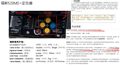
• 阀门初次整定时: 使用蓝色按键长按5秒进入自整定。
• 当阀门整定无动作时: 使用按键进入菜单,选择Configuration-Factory Reset。
将定位恢复出厂设置,删除当前配置后重新整定,约2-3次 后整定可以通过。 • 当更换后定位器无法通过时:
打开定位器盖板,将齿轮处分开, 把标记点移动到区间范围内再次 整定尝试。
Valve Stability(阀门稳定性) -Lo Friction(低摩擦)Hi Friction(高摩擦)
Main Menu 主菜单
菜单树状图
Status Alerts&Alarms
Current Alram Event History
Partial Stroke
Start Test Results
Valve Action(阀门动作形式) -Double(双作用)Single(单作用)
Signal at Closed(关信号) - 4mA -20mA
Characterization(特性)
-Linear(线性)Other(其他)
Auto Tune(自动调谐)
-On-பைடு நூலகம்ff
Quick Calibration(快速校验) -Auto(自动)Jog(点动)
福斯LogiIQ智能定位器调试说明

福斯L o g i I Q智能定位器调试说明Final revision on November 26, 2020L o g i x3200I Q智能定位器调试说明一、简介Logix3200IQ智能定位器接受4-20mA模拟量输入,4-20mA模拟量输出。
二、定位器操作面板介绍Logix3200IQ智能定位器就地操作面板由能够自动调校零点和满量程的QUICK-CAL快速调校按钮与可以手动操作定位器的两个点动按钮(↑和↓)以及八个DIP开关和可以调节定位器增益的旋转开关组成。
三、定位器DIP开关的设置定位器运行之前,首先设置DIP开关,下面就每一个DIP开关的设置进行了说明1、作用方式作用方式分气开式(ATO)和气关式(ATC)两种,调试前根据阀门的类型进行设置。
2、阀门关闭的信号4mA信号4mA时阀门处于全关位置,信号20mA时阀门处于全开位置20mA信号20mA时阀门处于全关位置,信号4mA时阀门处于全开位置3、阀位与信号对应曲线线性曲线(Linear)阀门位置与信号成线性关系选择曲线(Optional)选择了这个按钮,就激活了下一个DIP开关4、可选择曲线%=阀位与信号成等百分比Custom用户自定义曲线5、自动校准on每次按动QUICK-CAL按钮,定位器就自动调整参数进行调试off每次调试时,只能根据出厂前的预设置即调节定位器增益的旋转开关的位置进行调试无论哪一种情况,调节定位器增益的旋转开关都可以进行调节,调节完毕,不用重新进行调试,是即时生效的。
6、稳定性开关Low-FrictionValves适用低摩擦力调节阀High-FrictionValves适用高摩擦力调节阀7、备用开关8、定位器调试方式Auto定位器自动调试Jog手动调试,用户可以根据需要手动确定阀门的100%的位置四、手动点动调试首先将调校DIP开关拨到Jog位置,用户只能手动设置满量程,不能设置全关位,阀门全关位为默认状态。
