美卓定位器说明中文版的
MEITRACK T399G车辆追踪器用户指南说明书
MEITRACK T399G Vehicle TrackerUser GuideChange HistoryContents1 Copyright and Disclaimer........................................................................................................................................... - 5 -2 Product Introduction ................................................................................................................................................. - 5 -2.1 Product Features........................................................................................................................................... - 5 -2.1.1 LoRa communication ........................................................................................................................... - 5 -2.1.2 K211G Status Monitoring..................................................................................................................... - 6 -2.1.3 Harsh Acceleration/Braking Alert......................................................................................................... - 6 -2.1.4 GPS Data Filtering ................................................................................................................................ - 7 -2.1.5 Activating Output by Event .................................................................................................................. - 7 -2.1.6 Idling Detection.................................................................................................................................... - 8 -2.1.7 Changing I/O Port Mode ...................................................................................................................... - 8 -2.1.8 Auto Arming......................................................................................................................................... - 8 -2.1.9 Starting the Engine by RFID/iButton .................................................................................................... - 9 -3 Product Functions and Specifications........................................................................................................................ - 9 -3.1 Product Functions......................................................................................................................................... - 9 -3.1.1 Position Tracking .................................................................................................................................. - 9 -3.1.2 Anti-Theft............................................................................................................................................. - 9 -3.1.3 Other Functions ................................................................................................................................. - 10 -3.1.4 Functions of Optional Accessories ..................................................................................................... - 10 -3.2 Product Specifications ................................................................................................................................ - 10 -4 T399G and Accessories............................................................................................................................................ - 11 -5 Appearance.............................................................................................................................................................. - 12 -6 First Use................................................................................................................................................................... - 12 -6.1 Installing the SIM Card................................................................................................................................ - 12 -6.2 LED Indicator............................................................................................................................................... - 13 -6.3 Device Configuration .................................................................................................................................. - 13 -6.3.1 Installing the USB Driver .................................................................................................................... - 13 -6.3.2 Configuring Device Parameters by Meitrack Manager....................................................................... - 14 -6.3.3 Binding the K211G ............................................................................................................................. - 15 -6.3.4 Unbinding the K211G......................................................................................................................... - 15 -6.4 Tracking by Mobile Phone........................................................................................................................... - 16 -6.5 Common SMS Commands .......................................................................................................................... - 17 -6.5.1 Real-Time Location Query – A00........................................................................................................ - 17 -6.5.2 Setting Authorized Phone Numbers – A71 ........................................................................................ - 17 -6.5.3 Setting the Smart Sleep Mode – A73 ................................................................................................. - 17 -6.5.4 Controlling Output Status – C01 ........................................................................................................ - 18 -6.5.5 Setting I/O Port Status – C08 ............................................................................................................. - 18 -6.5.6 Setting Idling Time – D34 ................................................................................................................... - 19 -7 MS03 Tracking System ............................................................................................................................................. - 20 -8 Installing the T399G................................................................................................................................................. - 20 -8.1 Installing an I/O Cable................................................................................................................................. - 20 -8.1.1 Interface Definition............................................................................................................................ - 20 -8.1.2 Wiring Diagram .................................................................................................................................. - 21 -8.1.3 Setting Code Matching of the RF Remote Control ............................................................................. - 23 -8.2 Mounting the T399G................................................................................................................................... - 24 -1Copyright and DisclaimerCopyright © 2019 MEITRACK. All rights reserved.and are trademarks that belong to Meitrack Group.The user manual may be changed without notice.Without prior written consent of Meitrack Group, this user manual, or any part thereof, may not be reproduced for any purpose whatsoever, or transmitted in any form, either electronically or mechanically, including photocopying and recording.Meitrack Group shall not be liable for direct, indirect, special, incidental, or consequential damages (including but not limited to economic losses, personal injuries, and loss of assets and property) caused by the use, inability, or illegality to use the product or documentation.2Product IntroductionThe T399G is a multi-purpose vehicle tracker. It not only can be used for tracking and positioning, but also used for K211G GPS smart lock management. It has an ability to monitor and record K211G status in real time, and to systematically manage the connection status, battery power and alerts of the K211G. This unit features an IP67 water resistance rating, is equipped with built-in GPS and GSM antennas, and can work in different environments. When it works with the K211G, it can be installed into trailers and box trucks. When it works alone, it can be installed into cars, motorcycles, yachts, boats, etc.2.1Product Features2.1.1LoRa communicationThis function is used for communication between the T399G and the K211G GPS smart lock. After the LoRa connection is successful, the K211G will send information such as lock status information, alert events and battery power to the T399G via LoRa. Then the T399G will upload K211G status information to the server at specific interval via GPRS network and will monitor the K211G status in real time.2.1.2K211G Status Monitoring2.1.3Harsh Acceleration/Braking AlertYou can detect the harsh acceleration/braking alert by setting the limit value. Cautions on device installation:1.The device should be installed into the vehicle according to the following direction.2.The device installation angle cannot exceed 15 degrees.The default harsh acceleration and braking alert values are 230 mG and -300 mG respectively.Note: The alert results vary according to the device installation, vehicle model, vehicle weight, and driving behaviors. After the device has been installed properly, you can use the Meitrack Manager software to adjust the harsh acceleration and braking alert values by every 10 mG. You can also use the D79 command to set the values.2.1.4GPS Data FilteringThe GPS data filtering function can ensure GPS data accuracy and eliminate static drift.You can set the following parameters by Meitrack Manager: GPS speed range, GPS positioning accuracy, and Number of GPS satellites. When the GPS data filtering function is enabled, if all conditions are met, GPS data will be updated.Note: This function can be enabled by Meitrack Manager.2.1.5Activating Output by EventYou can activate output by event.For example:1.When speeding is detected, the device can control buzzer sounds.2.When unauthorized ignition or GPS antenna cut-off is detected, the engine will not be able to start.3.When iButton triggering is detected, the device can control engine startup.4.When input or output status is detected, the output will be active or inactive.2.1.6Idling DetectionThis function is used to detect whether a vehicle's engine is switched off while parking. To enable the function, you must connect input 2 to ACC detection.When the device detects that the driving speed is 0 and the ACC is on for one consecutive minute (default time), an idling alert will be generated.For details, see section 6.5.6 "Setting Idling Time – D34."2.1.7Changing I/O Port ModeThis function is used to change the I/O port mode. For example, change active negative input to analog port or positive input.For details, see section 6.5.5 "Setting I/O Port Status – C08."2.1.8Auto ArmingYou can enable the auto arming function by B27 command, Meitrack Manager software or MS03 tracking platform. This function is disabled by default.When the device is in sleep mode and the function has been enabled, the device will enter auto arming state.You can set disarming by B21 command or remote control.Note:1.To implement the fuel/power cut-off function for a vehicle theft alert, you should select the vehicle theft eventin the Output 1 column on the Meitrack Manager software.2.To implement the alert function of the buzzer, you should set the 1-Wire interface (green cable) to alert output.2.1.9Starting the Engine by RFID/iButtonAfter swiping the authorized RFID card or the authorized iButton key touches the iButton reader, the driver must start the engine within 1 minute. Otherwise, the tracker's output 1 will be triggered (engine cut-off), and thus the driver cannot start the vehicle. At the moment, if you want to start the engine, you must swipe the iButton key/RFID card again.Before starting the engine, ensure that:1.The tracker's input 2 is connected to the engine detection cable.2.An iButton key or RFID card has been authorized.3.The tracker's output 1 is connected to the engine control cable through a relay.4.The RFID ignition function has been enabled by Meitrack Manager or MS03 tracking platform.5.The RFID event has been enabled on Meitrack Manager.3Product Functions and Specifications3.1Product Functions3.1.1Position Tracking●GPS + LBS positioning●Real-time location query●Tracking by time interval●Tracking by distance●Tracking by mobile phone●Speeding alert●Cornering report3.1.2Anti-Theft●Polygonal geo-fence alert●Engine or vehicle door status alert●Remote vehicle fuel/power cut-off●GPS blind spot alert●Towing alert3.1.3Other Functions●SMS/GPRS (TCP/UDP) communication●Built-in 8 MB buffer for recording driving routes ●IP67 water-resistance rating●Mileage report●Roaming parameter settings●Smart sleep mode●Built-in 3-axis accelerometer●Online Parameter Editor●GPS data filtering●Activate output by event●Stop Moving and Start Moving alerts●Vehicle power protection●Idling alert●AGPS3.1.4Functions of Optional Accessories3.2Product Specifications4T399G and AccessoriesT366G and standard accessories:●T366G tracker (with a cable of 50 cm in length) ●400 mAh battery (-20°C to 60°C)●L wrench●Hexagon screw●CD download card5Appearance6First Use6.1Installing the SIM Carde the screwdriver to open the back cover.SIM card slot Firmware upgrade button Power buttonGSM indicator USB portGPS indicator2.Insert the SIM card into the card slot (card chip facing down).3.Close the cover, and tighten the screws.Note:●Power off the device before installing the SIM card.●Ensure that the SIM card has sufficient balance.●Ensure that the phone card PIN lock has been closed properly.●Ensure that the SIM card in the device has subscribed the caller ID service if you want to use your authorizedphone number to call the device.6.2LED IndicatorPress and hold down the power button for 3–5 seconds to start the device.6.3Device Configuration6.3.1Installing the USB Driver1.Decompress the stsw-stm32102.zip file provided by Meitrack, locate the following file, and install the USBdriver on a computer with 64-bit Windows system.2.After the installation is finished, connect the tracker to the computer by USB cable. If STMicroelectronicsVirtual COM Port (COM5) is displayed on the Computer Management page, the driver is installed successfully.Note: Before connecting the device to the computer by USB cable, turn on the device first. Otherwise, it cannot be detected by Meitrack Manager.Note: After you finish the driver installation, if the preceding figure is not displayed, copy the mdmcpq.inf file to the c:/windows/inf/directory and usbser.sys file to the C:/windows/system32/drivers/directory. Then restart the computer.6.3.2Configuring Device Parameters by Meitrack ManagerThis section describes how to use Meitrack Manager to configure the device on a computer.Operation steps:1.Install the USB driver and Meitrack Manager.2.Connect the device to a computer by using the USB cable.3.Run Meitrack Manager (6.0.0.9 version or later), then the following dialog box will appear:4.Turn on the device, then Meitrack Manager will automatically detect the device model and the parameter pagewill appear accordingly.For details about Meitrack Manager, see the MEITRACK Manager User Guide.6.3.3Binding the K211GTo make the T399G and K211G communicate with each other via LoRa, bind the two devices. After the binding is successful, the T399G can communicate with multiple K211G devices, and will upload lock status information and alerts of multiple K211G devices to the server.Perform the following steps to bind the K211G:1.Go to the Peripheral page of Meitrack Manager.2.Enter the IMEI number of the K211G.3.Click Binding.4.Click Set.After the binding is successful, the IMEI number of the K211G will displayed on the Head Tracker Information area.6.3.4Unbinding the K211GThis operation is used to disconnect the communication between the T399G and the K211G. After the unbinding is successful, the T399G will not obtain status information and alerts of the K211G.Perform the following steps to unbind the K211G:1.Go to the Peripheral page of Meitrack Manager.2.Select the IMEI number to be unbounded.3.Click Unbind.4.Click Set.6.4 Tracking by Mobile PhoneCall or send the 0000,A00 command by SMS to the device's SIM card number. The device will reply to an SMS with a map link.Click the SMS link. The device's location will be displayed on Google Maps on your mobile phone.Note: Ensure that the device's SIM card number has subscribed the caller ID service. Otherwise, the tracking function by mobile phone will be unavailable.SMS example:Now,061314 10:36,V,26,0Km/h,96%,/?lat=22.513781&lng=114.057183 The following table describes the SMS format:If your mobile phone does not support HTTP, enter the latitude and longitude on Google Maps to query a location.6.5Common SMS Commands6.5.1Real-Time Location Query – A00SMS sending: 0000,A00SMS reply: Now,Date and time,Positioning status,GSM signal strength,Speed, Remaining battery power,Map link Description: This command is used to query tracker's current location.Example:Sending: 0000,A00Reply: Now,160721 16:40,V,12,56Km/h,97%,/?lat=22.513015&lng=114.0572356.5.2Setting Authorized Phone Numbers – A71SMS sending: 0000,A71,Phone number 1,Phone number 2,Phone number 3SMS reply: IMEI,A71,OKDescription:Phone number: A phone number has a maximum of 16 bytes. If no phone numbers are set, leave them blank. Phone numbers are empty by default.Phone number 1/2/3: Set these phone numbers to authorized phone numbers. When you call the tracker by using these phone numbers, you will receive SMS notification about the location, geo-fence alert and low power alert and SMS notification or a call about the unauthorized door open and unauthorized ignition.If you need to delete all authorized phone numbers, send 0000,A71.Example:Sending:0000,A71,138****1111,138****2222,138****3333Reply: 353358017784062,A71,OK6.5.3Setting the Smart Sleep Mode – A73SMS sending: 0000,A73,Sleep levelSMS reply: IMEI,A73,OKDescription:When the sleep level is 0, the sleep mode is disabled (default).When the sleep level is 1, the tracker enters the normal sleep mode. The 3G module always works, and the GPS module occasionally enters the sleep mode. The tracker works 25% longer in the normal sleep mode than that in the normal working mode. This mode is not recommended for short interval tracking; this will affect the route precision. When the sleep level is 2, the tracker enters the deep sleep mode. If no event (SOS, button changes, incoming calls, SMSs, or vibration) is triggered after five minutes, the GPS module will stop working, and the 3G module will enter sleep mode. Once an event is triggered, the GPS and 3G modules will be woken up.Note: In any condition, you can use an SMS command to disable the sleep mode, and then the tracker exits the sleep mode and returns back to the normal working mode.Example:Sending: 0000,A73,2Reply: 353358017784062,A73,OK6.5.4Controlling Output Status – C01SMS sending: 0000,C01,Speed,ABCDESMS reply: IMEI,C01,OKDescription:When the speed is 0, no speed limit exists. That is, when the tracker receives a command, the output control takes effect immediately.When the speed is a value ranging from 1 to 255 (unit: km/h), set the speed limit for output control. When the driving speed is lower than the speed limit, the output control takes effect.ABCDE: indicates the output 1, output 2, output 3, output 4, and output 5 respectively. When the parameter value is 0, the output is disabled. When the parameter value is 1, data will be generated according to preset output mode. When the parameter value is 2, previous status will be remained.Example:Sending: 0000,C01,10,10000Reply: 353358017784062,C01,OK6.5.5Setting I/O Port Status – C08SMS sending: 0000,C08,IO0:Mn,IO1:Mn,IO2:Mn,IO3:Mn,IO4:MnSMS reply: IMEI,C08,IO0:Mn,IO1:Mn,IO2:Mn,IO3:Mn,IO4:MnDescription:1.IO0, IO1, IO2, IO3, and IO4 indicate I/O ports.IO0: open collector 1 by default (yellow cable)IO1: 1-Wire interface by default (green cable)IO2: negative input 1 by default (grey cable)IO3: positive input 2 by default (white cable)IO4: AD input 1 by default (blue cable)2.Mn indicates the I/O port status. The parameter value is as follows:0: low trigger1: high trigger2: AD input3: Remote control input4: open collector5: low output6: PWM output7: Buzzer alert output8: 1-Wire3.You can set one or multiple input ports at the same time. The command 0000,C08 is used to read I/O portparameters.Note:1.IO0: Mn parameter value is 4, 5, or 6.2.IO1: Mn parameter value is 0, 4, 5, 7, or 8.3.IO2: Mn parameter value is 0, 1, or 2.4.IO3: Mn parameter value is 0, 1, or 2.5.IO4: Mn parameter value is 0, 1, 2, or 3.Example:Sending: 0000,C08,IO0:5Reply: 353358017784062,C08,IO0:5,IO1:0,IO2:2,IO3:2,IO4:16.5.6Setting Idling Time – D34SMS sending: 0000,D34,TimeSMS reply: IMEI,D34,OKDescription:Time: When the device detects that the driving speed is 0 and the ACC is on (input 2 activated) for consecutive several minutes, an idling alert will be generated.Value range: 0–65536; unit: minute; default value: 1 minuteExample:Sending: 0000,D34,1Reply: 353358017784062,D34,OKFor details about SMS commands, see the MEITRACK SMS Protocol.Note:1.The default SMS command password is 0000. You can change the password by using Meitrack Manager andSMS command.2.The device can be configured by SMS command with a correct password. After an authorized phone number isset, only the authorized phone number can receive the preset SMS event report.7MS03 Tracking SystemVisit , enter the user name and password, and log in to the MS03. (Purchase the login account from your provider.)For more information about how to add a tracker, see the MEITRACK GPS Tracking System MS03 User Guide (chapter 4 "Getting Started").The MS03 supports the following functions:●Track by time interval or distance.●Query historical trips.●Set polygonal geo-fences.●Bind driver and vehicle information.●View various reports.●Send commands in batches.●Support OTA updates.For details, see the MEITRACK GPS Tracking System MS03 User Guide.8Installing the T399G8.1Installing an I/O Cable8.1.1Interface DefinitionThe I/O cable is an 8-pin cable, including the power, analog input, and negative/positive input and output interfaces.The I/O cable of T399G RS232 version is an 11-pin cable. Besides the above 8 pins, there are the following 3 pins.8.1.2Wiring DiagramT399G standard version:T399G RS232 version:8.1.3Setting Code Matching of the RF Remote ControlAfter the cover of the remote control receiver is removed, there will be a purple cable, as shown in the following figures.Remove the coverPerform the following steps to set code matching:1.Connect the remote control receiver's yellow cable to 5 V power supply and code matching cable (purple) toGND for more than 2 seconds.2.Press any key of the remote control, and then press any key of the other remote control.3.Release the code matching cable of the remote control receiver.4.Enable the SMS/GPRS events of arming and disarming, and use the remote control to set arming or disarming.If an SMS or GPRS event is received, the code matching is set successfully.Definitions of RF Remote Control Keys:Arm keyNote: The buzzer connects to the 1-Wire interface (green cable), which needs to be set to output 2.8.2Mounting the T399GMount the device in the vehicle by cable tie.Note: Do not install it at a metal covered place.Ifyouhaveanyquestions,*****************************************.。
美卓(mesto)nelesnd9000定位器校验

进入参数设置界面方法
1.按下不松开,再按即可进入主菜单界面(首先显示的是“MODE”);
2.按显示“PAR”,这是参数设置的主菜单名称;
3.按开始进行参数的查看与设置等调试工作。
使用方法
1.当某一参数出现在屏幕上时,稍微用力按下,下面一行可选参数开始闪烁,这时进入编辑状态;
2.用、来进行选择;
3.用来确认操作,同时退出编辑状态。
校验
检验仅工作在AUTO模式下。
进入校验界面方法
1.按下不松开,再按即可进入主菜单界面(首先显示的是“MODE”);
2.按一次或者按两次即显示“CAL”,这是校验菜单;
3.按开始进行调试。
“AUTO CAL”是自动校验;
“MAN CAL”是手动校验;
“TUNE”表示自诊断功能;
“CAL run”表示正在进行校验。
使用方法
1.按下,用、选择“AUTO CAL”或“MAN CAL”或“TUNE”(使用自诊断功能并准备开始校验);
2.前两种情况下,需要进一步选择是否使用自诊断功能;
3.校验自动结束,按返回主菜单“CAL”。
GPS12翻译版说明书
GPS12使用手册首先感谢您选择了GARMIN GPS12,这是一款使用简单,携带方便的GPS导航仪。
其致力于长时间提供优质的导航服务和良好的人机互动。
为了更好地使用本产品,请仔细阅读使用说明书!为了方便理解,本说明书分为四个部分:简介部分:对操作手册一些专业术语简要概述;入门部分:介绍了本产品的基本特征,简述了利用GPS12快速定位的方法;参考部分:说明了GPS12的先进功能及操作细节;附录部分:包含初始化说明和其他多个操作,如地图基准,时间偏移,索引。
在开始使用GARMIN GPS12之前,请仔细检查以下的几个地方:如有缺失任何部件,请立即与经销商联络。
标准配件:GARMIN GPS12;使用说明书;腕带;快速使用手册。
经销商应提供的配件有:GARMIN GPS12包;旋转接头;外接天线;电源/数据线。
我们希望本产品能尽可能满足您的导航需求,我们将尽我们最大的努力让其成为一款优秀的户外设备。
IGPS系统是美国开发的一套系统,其负责该系统的维护与准确性。
该系统如有变化将会影响所有GPS设备的准确性及使用性能。
虽然GPS12是一种精密电子导航系统(导航设施),但是如果误操作或者误解其用途,那么该系统将不再安全。
个人使用GPS12一些要求:为了减少不安全操作的风险,应仔细阅读和理解本操作手册的各方面并利用模拟系统进行操作练习。
在实际使用时,应结合其他导航设备包括从其他助航设备,目视瞄准,地图等信息仔细比较GPS12的信息显示。
出于安全考虑,须在继续航行之前解决任何误差。
注意:此装置符合FCC的第15部分对家庭或办公室使用的B类数字设备的限额要求。
它已经过测试,符合所有必要的FCC标准(FCC:全称美国联邦通讯委员会Federal Communications Commission)。
本产品通过无线电进行通信,如不按其操作规程使用,则会对信号的准确性有很大的影响。
当然,在按照规则合理使用设备时,也不能排除其他设备对本产品的干扰,当遇到干扰时,可以通过重启来恢复使用,当然,远离干扰源或连接该设备到其他的系统也是避免干扰的有效措施。
(完整版)美卓(MESTO)NelesND9000定位器校验
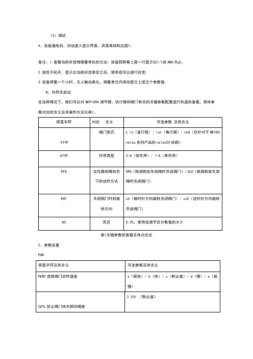
进入参数设置界面方法
1.按下不松开,再按即可进入主菜单界面(首先显示的是“MODE”);
2.按显示“PAR”,这是参数设置的主菜单名称;
3.按开始进行参数的查看与设置等调试工作。
使用方法
1.当某一参数出现在屏幕上时,稍微用力按下,下面一行可选参数开始闪烁,这时进入编辑状态;
2.用、来进行选择;
3.用来确认操作,同时退出编辑状态。
校验
检验仅工作在AUTO模式下。
进入校验界面方法
1.按下不松开,再按即可进入主菜单界面(首先显示的是“MODE”);
2.按一次或者按两次即显示“CAL”,这是校验菜单;
3.按开始进行调试。
“AUTO CAL”是自动校验;
“MAN CAL”是手动校验;
“TUNE”表示自诊断功能;
“CAL run”表示正在进行校验。
使用方法
1.按下,用、选择“AUTO CAL”或“MAN CAL”或“TUNE”(使用自诊断功能并准备开始校验);
2.前两种情况下,需要进一步选择是否使用自诊断功能;
3.校验自动结束,按返回主菜单“CAL”。
metso_neles_NDX系列智能阀门定位器原理和应用
Metso-neles NDX 系列智能阀门定位器原理和应用李宝华摘要:metso (美卓)旗下的neles (耐莱斯)在阀门定位器领域有着超过五十年的研发和生产经验,智能阀门定位器高端产品方面已有ND9000系列和ND7000系列,而技术研发始终以市场需求为导向,根据工业领域各应用客户的需求和建议来推动新品研发,美卓于2016年新推出一款NDX 系列智能阀门定位器,主要针对应用HART 通信的一般用户,适用于各个工业领域的单作用气动执行机构/控制阀,为不同用户提供通用的解决方案和设备智能管理的技术支持。
关键词:NDX ;智能阀门定位器;原理;结构;应用引言metso (美卓)旗下的neles (耐莱斯)在阀门定位器领域有着超过五十年的研发和生产经验,参见图1,从1961年生产第一台NP 系列气动阀门定位器开始,又先后推出NE 系列电气阀门定位器和ND800系列智能阀门定位器,之后在ND800基础上研发新一代智能阀门定位器,2003年发布ND9000系列智能阀门定位器,2010年推出增强的故障诊断、在线诊断以及具有鲁棒性、控制性能改善的ND9000系列新版本,随后在2013年推出ND9000固件简化后的ND7000系列智能阀门定位器,ND9000系列和ND7000系列均属智能阀门定位器高端产品,得到市场广泛认可。
美卓的技术研发始终以市场需求为导向,根据工业领域各应用客户的需求和建议来推动新品研发,于2016年新推出一款NDX 系列智能阀门定位器,主要针对应用HART 通信的一般用户,具有超群的性能、独特的增强版诊断、高可靠性和高可用性,适用于各个工业领域的单作用气动执行机构/控制阀,易于安装和组态,可为不同应用提供通用的解决方案、可靠服务和设备智能资产管理的技术支持。
NDX 系列与ND9000/7000系列形成产品层级搭配,有利于多品种差异化选择对比营销。
NDX 系列智能阀门定位器图1 metso-neles 阀门定位器的发展历程图2 metso-neles NDX 系列智能阀门定位器NDX系列智能阀门定位器参见图2,结构分解图参见图3。
美追MEITRACK K211G GPS智能锁用户指南说明书
MEITRACK K211G GPS Smart LockUser GuideApplicable Model: K211GChange HistoryContents1 Copyright and Disclaimer........................................................................................................................................... - 4 -2 Product Introduction ................................................................................................................................................. - 4 -2.1 Product Features........................................................................................................................................... - 4 -2.1.1 LoRa Communication (Optional).......................................................................................................... - 4 -2.1.2 Locking or Unlocking the K211G .......................................................................................................... - 5 -2.1.3 Dual SIM Cards..................................................................................................................................... - 6 -2.1.4 Magnetic Charging............................................................................................................................... - 7 -2.1.5 Strong Magnetic Adsorption................................................................................................................ - 7 -2.1.6 Anti-collision Soft Adhesive ................................................................................................................. - 8 -2.1.7 Security Performance - Super Password .............................................................................................. - 8 -3 Product Functions...................................................................................................................................................... - 9 -3.1 Position Tracking........................................................................................................................................... - 9 -3.2 Alerts ............................................................................................................................................................ - 9 -3.3 Other Functions .......................................................................................................................................... - 10 -4 Product Specifications ............................................................................................................................................. - 10 -5 Main Device and Accessories .................................................................................................................................. - 11 -6 First Use................................................................................................................................................................... - 11 -6.1 Installing a SIM Card ................................................................................................................................... - 11 -6.2 Turning on the K211G ................................................................................................................................. - 12 -6.3 LED Indicator............................................................................................................................................... - 13 -6.4 Device Configuration .................................................................................................................................. - 13 -6.4.1 Installing the USB Driver .................................................................................................................... - 13 -6.4.2 Configuring Device Parameters by Meitrack Manager....................................................................... - 14 -6.5 Binding or Unbinding the T399G ................................................................................................................ - 15 -6.5.1 Binding the T399G ............................................................................................................................. - 15 -6.5.2 Unbinding the T399G......................................................................................................................... - 15 -6.6 Common SMS Commands .......................................................................................................................... - 16 -6.6.1 Setting GPRS Parameters – A21 ......................................................................................................... - 16 -6.6.2 Setting a Smart Sleep Mode – A73 .................................................................................................... - 16 -6.6.3 Setting the Maximum Working Time of the Woken GPS Module – A83 ............................................ - 16 -6.6.4 Setting the SMS Time Zone – B35 ...................................................................................................... - 17 -6.6.5 Disabling the Power-off Function of the Power Button – C77 ........................................................... - 17 -6.6.6 Authorizing an RFID Card – D10......................................................................................................... - 17 -6.6.7 Authorizing RFID Cards in Batches – D11........................................................................................... - 17 -6.6.8 Locking or Unlocking the K211G – D82.............................................................................................. - 18 -6.6.9 Selecting a Locking Method – D83..................................................................................................... - 18 -6.6.10 Setting the automatic authorization time of swiping the RFID card – DB0...................................... - 18 -6.6.11 Changing Super Password – F22 ...................................................................................................... - 19 -7 Using the Platform................................................................................................................................................... - 19 -7.1 MS03 Tracking System ................................................................................................................................ - 19 -7.2 Authorizing RFID Cards in Batches by MS03 ............................................................................................... - 19 -8 Device Installation ................................................................................................................................................... - 21 -1 Copyright and DisclaimerCopyright ©2019 MEITRACK. All rights reserved.,andare trademarks that belong to Meitrack Group and its subsidiary.The user manual may be changed without notice.Without prior written consent of Meitrack Group, this user manual, or any part thereof, may not be reproduced for any purpose whatsoever, or transmitted in any form, either electronically or mechanically, including photocopying and recording.Meitrack Group shall not be liable for direct, indirect, special, incidental, or consequential damages (including but not limited to economic losses, personal injuries, and loss of assets and property) caused by the use, inability, or illegality to use the product or documentation.2 Product IntroductionThe K211G is a GPS smart lock that supports Long Range (LoRa) and GPRS communication. Its main functions include real-time lock status monitoring, anti-tamper alert, anti-cut alert, swiping an RFID card to lock or unlock the device, and super long standby time. There is no button on the outer case of the device, and the IP67 water resistance rating makes the device withstand harsh environments ,and the device also has a crash-proof housing design. It is specially designed for door lock management in various land and sea transportation such as box trucks, trailers and containers.2.1 Product Features2.1.1 LoRa Communication (Optional)This function is used for communication between the K211G and the T399G vehicle tracker. After the LoRa connection is successful, the K211G will send information such as lock status information and battery power to the T399G via LoRa. To establish LoRa communication between the K211G and the T399G, the two devices must be bound each other. For details about how to bind the T399G to the K211G, see the section 6.5 "Binding or Unbinding the T399G."LoRa connection process:T399G and K211G communication features:Communication diagram2.1.2Locking or Unlocking the K211G Locking or Unlocking by Swiping RFID CardsThe function is used to lock or unlock the K211G by swiping authorized RFID cards. When you swipe an RFID card, the K211G will automatically detect and record the unlocking time, location and RFID card number, and these data will be sent to the server.Operation process: Put the authorized RFID card on the K211G's card swiping area. When the K211G detects this action, the buzzer will beep and the LVS LED indicator will be steady on, indicating that the K211G is unlocked. In this way, the last step for you is to pull out the lock rope. (To lock the K211G, you only need to swipe the RFID card once. Then the buzzer will beep and the LVS LED indicator will be off, indicating that the K211G is locked.)Swiping an RFID card:Note: In the locking or unlocking state, if you swipe an unauthorized RFID card, the buzzer will beep twice,but the K211G cannot be unlocked and locked. If you swipe an authorized RFID card, the buzzer will beep once. Before the K211G is locked,it is recommended to apply appropriate force on the lock rope first to make the waterproof ring of cable fully contact with the lock hole and improve the waterproof performance,and if the lock rope is cut, K211G cannot be locked. After the K211G is unlocked, if you do not pull out the lock rope within one minute, the K211G will be locked automatically.2.1.3Dual SIM CardsThe K211G can be installed with two Micro SIM cards and supports the dual SIM single standby mode. The device will automatically select a SIM card to register the network. SIM1 (on the right) will be selected by default. If SIM1 fails to register the network, SIM2 (on the left) will be selected to do this. (Please ensure that at least one SIM card can be used normally.)2.1.4Magnetic ChargingYou can use the magnetic charging cable to charge the K211G. The device supports 9V/2A power adapter, and it will take a total of 7.5–8 hours to charge the device fully.2.1.5Strong Magnetic AdsorptionThe back of the cover plate has strong magnetic, which can be adsorbed to the car door to prevent the device from shaking during movement.2.1.6Anti-collision Soft AdhesiveThe gray protruding part in the figure is Anti-collision soft adhesive, which has shock absorption effect and it can effectively protect the device from being damaged in the collision.2.1.7Security Performance - Super PasswordTo enhance security, K211G supports super password.Super password (the default is 666888) supports all SMS commands, but DB0 / D82 / D10 / D11 / D14 D15 / A21 / F22 commands can't use the original SMS password (the default is 0000), they can only use super password.When setting GPRS parameters through Meitrack Manager, you need to open the super password first before setting successfully:Note:It is recommended to set a new super password first, because the super password is related to the security of unlocking; The default super password is 666888, which can be modified by Meitrack Manager and F22 command.Please make sure to remember the super password, and the super password cannot be quested and reset to the original value, once you forget the password, it will not be able to recover.3Product Functions3.1Position Tracking●GPS + LBS positioning●Real-time location query●Tracking by time interval●Tracking by distance●Tracking by mobile phone●Speeding alert●Cornering report●Geo-fence3.2Alerts3.3Other Functions4Product Specifications5 Main Device and AccessoriesNote: Two RFID cards are standard, optional more and white type RFID card. The Power adapter(9V) can choose UL or VDE.6 First Use6.1 Installing a SIM CardRemove the four screws from the cover and take the cover out.GPS smart lock with the batteryLock rope (30 cm)RFID cardPower adapter(9V)Magnetic USB charging cableUSB cable CD download cardInsert a SIM card into one of the card slots (SIM1: right; SIM2: left).6.2Turning on the K211GPress the power button for 3 seconds. Then the GPS and GSM LED indicators will blink fast, indicating that the device is turned on.Note: When using the device for the first time, you are advised to charge the battery fully.6.3LED Indicator6.4Device Configuration6.4.1Installing the USB DriverInstall the USB driver on a computer with 64-bit Windows system.After the installation is finished, connect the K211G to the computer by USB cable. If Prolific USB-to-Serial Comm Port (COM3) is displayed on the Device Manager page, the driver is installed successfully.Note: Before connecting the K211G to the computer by USB cable, turn on the K211G first. Otherwise, it cannot be detected by Meitrack Manager.6.4.2Configuring Device Parameters by Meitrack ManagerThis section describes how to use Meitrack Manager to configure the K211G on a computer.Operation steps:1.Install the USB driver and Meitrack Manager.2.Connect the device to a computer by using the USB cable.3.Run Meitrack Manager (6.0.0.9 version or later), then the following dialog box will appear:4.Turn on the device, then Meitrack Manager will automatically detect the device model and the parameter pagewill appear accordingly.For details about Meitrack Manager, see the MEITRACK Manager User Guide.6.5Binding or Unbinding the T399G6.5.1Binding the T399GTo make the K211G and T399G communicate with each other via LoRa, bind the two devices. An IMEI number is the default binding information.Perform the following steps to bind the T399G:1.Go to the Peripheral page of Meitrack Manager.2.Enter the IMEI number of the T399G.3.Click Binding.4.Click Set.After the binding is successful, the IMEI number of the T399G will displayed on the GPS Smart Lock Information area.Note: To establish LoRa communication between the K211G and the T399G, the two devices must be bound each other. Please connect the T399G to the computer, and then repeat the above operations to bind the K211G.6.5.2Unbinding the T399GThis operation is used to disconnect the communication between the K211G and the T399G. After the unbinding is successful, the GPS positioning and GSM communication functions of the K211G will be enabled automatically. Lock status information will be uploaded to the server through the K211G.Perform the following steps to unbind the T399G:1.Go to the Peripheral page of Meitrack Manager.2.Select the IMEI number to be unbound.3.Click Unbind.4.Click Set.Note: The binding and unbinding functions are only available for the K211G with a LoRa module.6.6Common SMS Commands6.6.1Setting GPRS Parameters – A216.6.2Setting a Smart Sleep Mode – A736.6.3Setting the Maximum Working Time of the Woken GPS Module – A836.6.4Setting the SMS Time Zone – B356.6.5Disabling the Power-off Function of the Power Button – C776.6.6Authorizing an RFID Card – D106.6.7Authorizing RFID Cards in Batches – D116.6.8Locking or Unlocking the K211G – D826.6.9Selecting a Locking Method – D836.6.10Setting the automatic authorization time of swiping the RFID card – DB06.6.11Changing Super Password – F22Note: For details about SMS commands, see the MEITRACK SMS Protocol.7Using the Platform7.1MS03 Tracking SystemVisit , enter the user name and password, and log in to the MS03. (Purchase the login account from your provider.)For more information about how to add a device, see the MEITRACK GPS Tracking System MS03 User Guide (chapter 4 "Getting Started").The MS03 supports the following functions:●Track by time interval or distance.●Query historical trips.●Set polygonal geo-fences.●Bind driver and vehicle information.●View various reports.●Send commands in batches.●Support OTA updates.For details, see the MEITRACK GPS Tracking System MS03 User Guide.7.2Authorizing RFID Cards in Batches by MS031. On the main interface of the MS03, choose Management.2. On the Management window that is displayed, select Sending command from Use Normal.3. On the Sending command window that is displayed, set Command to Authorize RFID cards in batches, enter the RFID card start number and the number of cards, and click Send command.If only one RFID card needs to be authorized, the number of cards is 1. After the RFID cards are authorized successfully, you can swipe these cards to unlock and lock the K211G and record operator information.8Device InstallationIfyouhaveanyquestions,*****************************************.Copyright © 2019 Meitrack Group All rights reserved. - 21 -。
Armada Technologies Pro290 有线束导arter和电缆定位仪操作手册说明书

Armada Technologies Pro290Wire and Cable Locator Operating InstructionsThe Armada Technologies Pro290 wire and cable locator is designed to find lost or broken wires, and trace their paths. The complete Pro290 kit consists of;∙(1) Pro290R Receiving Wand and Antenna.∙(1) Pro290T Transmitter and Carrying Case and Leads.∙(1) ProGS Ground Stake.∙(1) Operating ManualPlease be sure that all items are included before operating the Pro290.Battery Installation - The Pro290 transmitter requires 8 “C” cell batteries. The Pro290 receiver requires one 9v battery. To install the batteries in the Pro290 transmitter, open the transmitter case and remove the 3 holding screws on the battery compartment located at the upper center of the unit. Place the batteries in the holder, orienting them in accordance with positive and negative poles. Turn on the Pro290T using the red on/off rocker switch. Connect the red and black alligator clips together. The red LED on the transmitter will now blink brightly indicating the batteries and unit are ready for operation. If no blinking light is seen, try adjusting the batteries to insure good connection. If the blinking is dim, be sure the batteries are good and fresh.The Pro290 receiver battery compartment is located on the backside of the Pro290R unit. Remove the battery compartment cover and install the 9 volt battery. Replace the cover.Setting up the Transmitter–Disconnect and de-energize the wire that you want to trace. With the transmitter off, connect the red lead to the wire you want to trace and the black lead to the included ground stake. Insert the ground stake into the soil. Do not use common grounds if possible as these may give false indications. It is important that the ground stake be in the soil and independent from common ground for best results. Turn the Pro290 transmitter on. The LED located on the Pro290 transmitter should now blink brightly. This LED is an indicator of how good the grounded connection is. The better the ground connection, the brighter the light. The Pro290 sets up a tracing circuit that travels down the wire, thru the ground, and back to the ground stake. It is important to note that the better the ground connection (indicated by a brightly blinking red LED), the better and easier the locate will be. A good ground is crucial for optimum operation. Soil conditions can also affect the ground connection. In general, the wetter the ground, the better the ground connection. Dry climates are more difficult to achieve good grounding. If the ground is dry, you may wish to moisten the grounding area with a cup of water, etc.Tracing Wire - After the Pro290 transmitter has been properly connected and verified to have a good ground and power, insert the receiver antenna into the female jack on the bottom of the yellow receiver box. Turn the Pro290 receiver on by turning the volume knob located on the side of the yellow receiver. Place the receiver near the operating Pro290 transmitter. With the antenna near the transmitter and the transmitter on, a beeping sound should be heard indicating that the receiver is working properly.A high pitched tone could indicate that you are too close to the receiver or your batteries are low. A fading signal indicates low battery. The volume control on the side of the receiver regulates the loudness of the receiver. After connecting and turning on the transmitter, and turning on the receiver, point the receiver toward the ground and listen for the beeping signal. The closer you are to the cable, the louder the signal.The Pro290 receiver uses a NULL signal tracing method. That means that when the antenna on the receiver is pointed directly at the cable, you will hear virtually nothing. However, by moving the antenna a few inches to the left or right, a signal can be heard. This is called NULL and it points directly to the path of the wire.Move along the path of the wire swinging the antenna, following the course of the loudest signal. From the beginning to the end of the cable, the cable location is the paththat emits the loudest signal outside the NULL boundaries (to the immediate left and right side).Finding Broken Wire – Breaks in wires can be found with the Pro290. The set up of the unit is the same as when tracing wire. The difference comes in the reception. Whereas the traced wire continues to emit a signal along the path of the cable, a break will cause the signal to stop at the point of break. Severe damage will cause the signal drop to a lower level but not necessarily end. Minor damage cannot be located with the Pro290 as not enough signal is dropped to notice a difference in response.Be sure the cable or wire you are tracking is grounded. THIS IS A MUST. The signal needs a path to return to the ground stake and without it, you will not get a good locate.A bad ground is indicated on the transmitter by observing a weak or no light on the LED. In many cases, a direct buried cable fault will provide this grounding and allow a locate. Helpful Hints– Increases in signal strength and/or the size of the area it is occurring from usually indicates some type of anomaly in the cabling. Things that could cause this are slack loops, nicks, cuts, bad splices, or cut wires. Good condition cable does not normally change the tone or strength, other than a very gradual loss of reception over distance or abrupt depth changes, but it is possible. Slack loops (extra wire coiled and buried) left in the ground at installation are an example of a condition that would cause an increase of signal and yet have no problem.Also, ground condition and moisture make a difference in the performance of the Pro290. Be sure your ground stake is secure, in the dirt and that the transmitter is connected to the cable you want to track.In addition, the more conductive the soil, the better. Dry sandy desert soil is not a good transmitter of signal and you will experience better results in moist soil. If you are in the desert, a little water at the ground stake may help.The best way to really learn the Pro290 is to use it. Set up a test site at your home or office and get used to how it works. There is no substitute for experience in the art of locating. Good luck!Warranty –Armada Technologies warranties all products for 12 months from manufacturing defects from the date of retail purchase. Armada Technologies will repair or replace any component that is returned to Armada Technologies within 12 months of purchase and does not exhibit signs of abuse or misuse. It is Armada Technologies sole discretion to determine this condition. Armada Technologies also reserves the right to require a proof of purchase in order to determine date and validity of purchase.Armada Technologies LLC.3596 76th St. SE, Caledonia, MI 49316 USA1-616-803-1080Rev 0513。
美卓定位器调试步骤
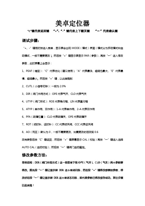
美卓定位器
“C”键代表返回键“+”、“-”键代表上下翻页键“←”代表确认键
调试步骤:
“+、-”键同时按进入菜单,显示屏会出现MODE(模式)界面(模式分为手动模式和自动模式,一般不需要更改)。
然后按“+”键显示屏显示PAR(参数),再按“←”进入修改参数,此时屏幕上会显示:
1、PEAF(增益):“C”代表优化(建议使用)、“A”代表最快、超调也最大、“E”代表最慢、超调最小。
然后按“+”键,以此类推到
2、CUTL(小信号切除):一般为2.0%
3、DIR(阀门作用方式):OPE代表气开、CLO代表气关
4、UTYP(阀门形式):ROE代表角行程、LIN代表直行程
5、ATYP(单作用、双作用):1-A代表单作用、2-A代表双作用
6、PFA(故障位置):CLO代表故障关、OPE代表故障开
7、ROT(顺时针、逆时针):CC代表顺关阀、CCC代表逆关阀
8、AO(死区):默认为0,一般不需要更改、如需更改的话改到0.6
改完参数后按“C”键返回,然后按“+”键屏幕显示CAL(校验)再按“←”键进入选择AUTO CAL(自动校验),然后按“←”键阀门自动整定。
修改参数方法:
举例说明:DIR(阀门作用方式)这一级菜单下有OPE(气开)、CLO(气关)两个参数要修改。
就先按“←”键让显示屏DIR这个单词闪烁,然后按“+”键修改想要的参数,修改好后按“←”键让显示屏DIR这个单词不闪烁,即代表参数已修改保存成功。
其它步骤以此类推!
手动设置:
先把模式改成MAN手动模式,然后返回界面后按“+”键到QPOS参数下,按“←”键显示屏闪烁,然后再按“+“、”-“键阀门就可以动作。
美卓定位器

Local User Interface (LUI)
CONFIDENTIAL
Single flapper with light aluminium coil structure. Excellent vibration characteristics due to balanced masses.
16
© Metso Date Author Title
Contactless and freely rotating shaft. No vibration effects, no wear, protected against humidity.´The A/D resolution is 4096 steps. Accurate pressure sensing is vital for the smooth control and effective valve condition monitoring
• Updated when:
All the time when the device is powered
• Indicates about:
- Correct sizing of the valve • Notice: - Especially useful when optimising
plant operation or replacing old control valves
- dead time - step response time (T86) - overshoot - gain
• Indicates
- control performance - Stability - operation speed
27
logix 3200(IOM)(chinese)
1 安全相关术语
安全术语危险、警告、小心和注意在本说明书中被 用来强调特定危险和/或提供更多的非显而易见的 信息。
β 危险:表示若不采取适当的防范措施将造成死
亡、严重的人身伤害和/或重大的财产损害。
χ 警告:表示若不采取适当的防范措施将可能造
成死亡、严重的人身伤害或重大的财产损害。
α 小心:表示若不采取适当的防范措施将可能造
警告:在对本产品或任何过程控制产品进行操作时 务必遵守标准的行业安全规范。具体来说,应保证 必须使用个人防护用品和升降装置。
3 拆除包装与储藏
3.1 拆除包装
1. 在拆除 Logix 3200MD 定位器的包装时,请对照 产品装箱单检查所交付的材料是否正确。每只 运输用集装箱内都附有系统和配件清单。
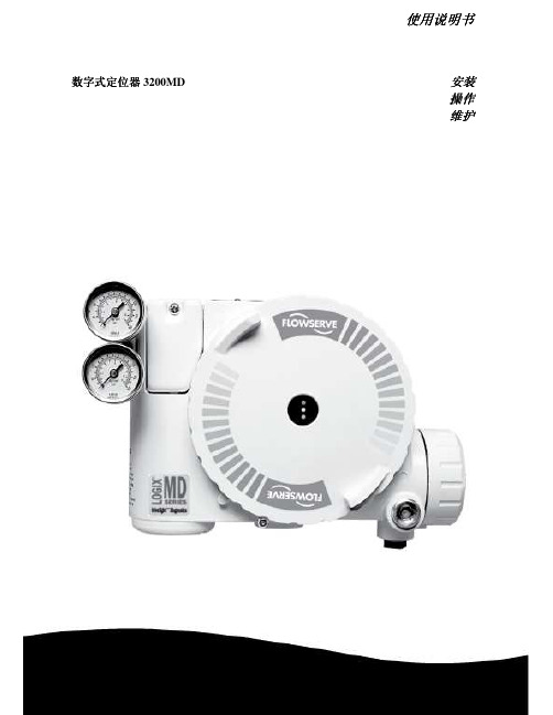
使用说明书用说明书用说明书用说明书数字式定位器数字式定位器数字式定位器数字式定位器3200md安装安装安装安装操作操作操作操作维护维护维护维护实践中积累经验实践中积累经验实践中积累经验实践中积累经验使用说明书数字式定位器3200mdlgenim0059011008目录目录目录目录31拆除包装32储藏33安装前的检查logix3200md定位器简介41规格42定位器操作43详细的定位器操作顺序51安装到valtekmarkone直通控制阀上52安装到标准型valtek旋转阀上53可选的valtek旋转安装程序1154将定位器用管连接至执行器上11布线与接地指南1261420毫安指令输入布线1362接地螺钉1363顺从电压1364电缆要求1365本质安全栅14启动1471logix3200md本地界面操作1472初始dip开关设定操作1473dip开关设定的配置操作1574快速校准操作模式下校准dip开关的设置1675快速校准quickcal操作1676阀门位置的本地控制1777恢复出厂设置1778指令重置1779版本号检查17710logix3200md指示状态17711valvesight配置诊断软件和hart375手持通信维护与维修2181驱动器模块总成2182调节器2383检查或设定内部调节器压力2484柱形阀2585柱形阀盖2586阀杆位置传感器2687主板pcb组件2788压力传感器板2789用户接口板28可选硬件2991通风口部设计2992hart调制调解器3093420毫安模拟量输出板3010零部件列表3211logix3200md备件箱3412logix3200md安装套件35121valtek安装套件35122logixoem
MASONEILAN定位器手操器说明
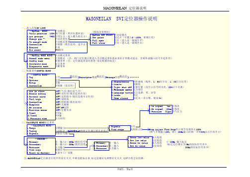
MASONEILAN 定位器说明共2页、第1页MASONEILAN 定位器说明共2页、第2页注:Masoneilan 定位器通上手操器后,打开的是‘正常模式’(NORMAL MODE )主画面,要进入上图第一个画面,必须先进‘手动模式菜单’(MANUAL MODE MENU ),再回退至‘HOME ’,即‘手动模式’(MANUAL MODE )主画面,此画面在调整回讯时有用。
对定位器操作完成后,必须切至‘正常模式’(NORMAL MODE ),否则总控信号不起作用。
回讯不到位调整方法定位器的反馈连接如图1所示:当手操器进入在线‘手动模式’ (MANUALMODE )主画面后,用第3项change pos<->来使阀门100%(选全开则阀门能开多大就开多大)、全关,并在100%、0%阀位时松开‘并紧螺母’,调整‘双头内螺纹螺杆’,使第1项Vavle position 阀位回讯值也为100%和0%,多调几次调好后拧紧‘并紧螺母’。
调完请重新再标定一次。
反馈联杆安装在不同的安装孔会有不同的阀位行程,越往里行程越小,而行程回讯都为100%(可能因为回讯电位器转够一定的角度即100%,阀位不再动作)。
当安装孔动过以后,如果行程不到位,标定是不能把行程标正常的。
回讯与阀位反向调整方法config mune ——setup ——Air to close (气关阀)项目与实际一致的话,用change pos<->把阀门调至全开,再用calibrate mune ——range ——find stops limit 去寻找停止位(输入100%),回讯就会与阀位一致。
注:标定约需10分钟,如果有大的错误如气源没有等,标定会很快终止并提示,如果回讯与阀位反向,标定可能会一直进行下去,标不完,此时要安上面方法调整。
图1:反馈连杆组件图。
GPS12翻译版说明书
GPS12使用手册首先感谢您选择了GARMIN GPS12,这是一款使用简单,携带方便的GPS导航仪。
其致力于长时间提供优质的导航服务和良好的人机互动。
为了更好地使用本产品,请仔细阅读使用说明书!为了方便理解,本说明书分为四个部分:简介部分:对操作手册一些专业术语简要概述;入门部分:介绍了本产品的基本特征,简述了利用GPS12快速定位的方法;参考部分:说明了GPS12的先进功能及操作细节;附录部分:包含初始化说明和其他多个操作,如地图基准,时间偏移,索引。
在开始使用GARMIN GPS12之前,请仔细检查以下的几个地方:如有缺失任何部件,请立即与经销商联络。
标准配件:GARMIN GPS12;使用说明书;腕带;快速使用手册。
经销商应提供的配件有:GARMIN GPS12包;旋转接头;外接天线;电源/数据线。
我们希望本产品能尽可能满足您的导航需求,我们将尽我们最大的努力让其成为一款优秀的户外设备。
IGPS系统是美国开发的一套系统,其负责该系统的维护与准确性。
该系统如有变化将会影响所有GPS设备的准确性及使用性能。
虽然GPS12是一种精密电子导航系统(导航设施),但是如果误操作或者误解其用途,那么该系统将不再安全。
个人使用GPS12一些要求:为了减少不安全操作的风险,应仔细阅读和理解本操作手册的各方面并利用模拟系统进行操作练习。
在实际使用时,应结合其他导航设备包括从其他助航设备,目视瞄准,地图等信息仔细比较GPS12的信息显示。
出于安全考虑,须在继续航行之前解决任何误差。
注意:此装置符合FCC的第15部分对家庭或办公室使用的B类数字设备的限额要求。
它已经过测试,符合所有必要的FCC标准(FCC:全称美国联邦通讯委员会Federal Communications Commission)。
本产品通过无线电进行通信,如不按其操作规程使用,则会对信号的准确性有很大的影响。
当然,在按照规则合理使用设备时,也不能排除其他设备对本产品的干扰,当遇到干扰时,可以通过重启来恢复使用,当然,远离干扰源或连接该设备到其他的系统也是避免干扰的有效措施。
Mio168 GPS 定位导航 Pocket PC 说明书

3
管理您的 Pocket PC....................................................................... 25
3.1 电源的管理 ....................................................................................... 25 电力不足........................................................................................... 25 智能型电源管理 ................................................................................ 26 省电提示........................................................................................... 26 内存的管理 ....................................................................................... 27 主内存 .............................................................................................. 27 存储卡 .............................................................................................. 27 设置您的 Pocket PC......................................................................... 28 设置密码........................................................................................... 29 个人数据管理和查找......................................................................... 29 将数据作备份 ................................................................................... 30 新建或删除程序 ................................................................................ 31 新建程序........................................................................................... 31 将程序加入开始菜单......................................................................... 32 删除程序........................................................................................... 32
ND9000系列智能阀门定位器的原理和应用
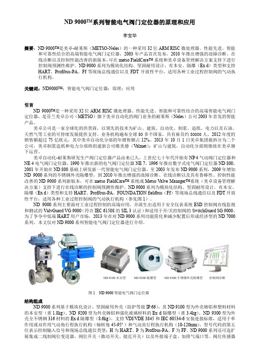
ND 9000™系列智能电气阀门定位器的原理和应用李宝华摘要:ND 9000™是美卓-耐莱斯(METSO-Neles )的一种采用32位ARM RISC 微处理器、性能先进、智能和可靠性结合的高端智能电气阀门定位器,2003年产品首次发布,2010年推出增强的故障诊断、在线诊断以及控制性能改善的新版本,可在metso FieldCare™ 系统和美卓设备管理解决方案支持下进行控制阀预测性维护。
ND 9000系列为模块化结构、坚固耐用设计,有本安、隔爆(Ex d )类型和支持HART 、Profibus-PA 、Ff 等现场总线通信以及FDT 开放性平台,适用各种工业过程控制阀的气动执行机构。
关键词:ND9000™;智能电气阀门定位器;原理;应用引言ND 9000™是一种采用32位ARM RISC 微处理器、性能先进、智能和可靠性结合的高端智能电气阀门定位器,是芬兰美卓公司(METSO )旗下美卓自动化的阀门业务的耐莱斯(Neles )公司2003年首发的智能产品。
美卓公司是一家全球化的供货商,以领先的技术为矿山、建筑、自动化、制浆、造纸、电力以及石油、天然气等工业的可持续发展提供支持。
业务机构遍布全球50多个国家,共有雇员约30000人,2012年度的销售额超过75亿欧元,其中美卓自动化分部的年销售额占12%。
2013年10月1日美卓集团被拆分为二个公司,美卓制浆造纸和电力分部将组建新公司维美德(V almet );矿山与建筑,自动化分部则继续在美卓旗下运营。
美卓自动化-耐莱斯研发生产阀门定位器产品由来已久,上世纪七十年代开始有NP 4气动阀门定位器和NE 4电气阀门定位器,1990年推出新的电气阀门定位器NE 7,1996年推出数字式电气阀门定位器ND 800,2001年开始在ND 800基础上研发新一代智能电气阀门定位器,至2003年发布ND 9000系列,2009年增加ND 9000系列的不锈钢外壳隔爆型,到2010年推出增强的故障诊断、在线诊断以及具有鲁棒性、控制性能改善的ND 9000系列新版本,可在metso FieldCare™ 系统或Metso V alve Manager™系统(美卓设备管理解决方案)支持下进行在线诊断的控制阀预测性维护。
V800中文说明书目录
V800中文说明书目录一、产品概述1.1 产品简介1.2 功能特点1.3 产品外观及按键说明二、使用准备2.1 包装清单2.2 安装电池2.3 腕带佩戴方法三、操作说明3.1 开机与关机3.2 主界面导航3.3 功能设置3.4 运动模式选择3.5 查看运动数据四、功能详解4.1 计步功能4.2 心率监测4.3 睡眠监测4.4 GPS定位4.5 消息提醒五、应用程序使用指南5.1 与安装5.2 注册与登录5.3 数据同步与查看5.4 设置与个性化六、维护与保养6.1 清洁与保养6.2 故障处理6.3 更换配件七、产品规格与参数7.1 技术规格7.2 尺寸与重量7.3 耐用性测试八、售后服务8.1 三包政策8.2 保修条款8.3 客服联系方式九、附录9.1 常见问题解答9.2 词汇表9.3 版本信息五、应用程序使用指南(续)5.4.1 个性化你的界面5.4.2 设置健康目标5.4.3 管理你的个人信息5.4.4 社交互动与分享5.4.5 更新应用程序与固件六、维护与保养(续)6.1.1 正确清洁表带和表盘6.1.2 避免在极端环境下使用6.1.3 存储建议6.2.1 故障诊断流程6.2.2 常见问题解决方法6.3.1 如何更换电池6.3.2 如何更换表带七、产品规格与参数(续)7.3.1 防水等级说明7.3.2 材质说明7.3.3 兼容性说明7.4 环保与安全性八、售后服务(续)8.1.1 三包凭证8.1.2 三包服务流程8.2.1 保修范围与期限8.2.2 保修凭证8.3.1 客服8.3.2 客服邮箱8.3.3 客服服务中心地址九、附录(续)9.1.1 运动与健康建议9.1.2 心率监测的正确使用方法9.1.3 睡眠质量评估标准9.2.1 专业术语解释9.2.2 简略英汉对照表9.3.1 产品版本更新记录9.3.2 用户反馈收集与改进十、用户故事与评价10.1 用户真实故事分享10.2 产品评价与建议10.3 加入我们的用户社区十一、安全注意事项11.1 使用前请仔细阅读本说明书11.2 未成年人使用注意事项11.3 驾驶时请勿使用11.4 警惕长时间使用可能带来的不适十二、法律声明12.1 知识产权声明12.2 隐私权保护政策12.3 责任限制与免责条款十、用户故事与评价(续)10.3.1 如何参与社区活动10.3.2 用户故事征集10.3.3 评价与建议的提交方式10.4 用户互动活动10.4.1 挑战赛与竞赛10.4.2 健康数据排行榜十一、安全注意事项(续)11.4.1 运动中的安全提示11.4.2 电池安全使用指南11.5 如何处理意外情况11.5.1 意外跌落11.5.2 液体侵入11.6 产品的正确废弃与回收十二、法律声明(续)12.3.1 产品责任12.3.2 免责条件12.4 用户协议12.4.1 使用条款12.4.2 隐私保护十三、联系我们13.1 客服联系方式汇总13.2 官方网站13.3 社交媒体平台13.4 反馈与建议十四、产品更新日志14.1 软件更新历史14.2 硬件更新记录14.3 更新说明与注意事项十五、环保倡议15.1 产品环保设计理念15.2 垃圾分类与回收15.3 减少电子废弃物通过这些内容的补充,我们希望V800智能手环不仅能够帮助您更好地监测和提升健康水平,还能让您感受到我们品牌的温度和责任感。
