patran官方教程--Ws19_GlobalLocal_disp
2019年在Patran界面中建立Dytran模型及后处理的操作过程实例6
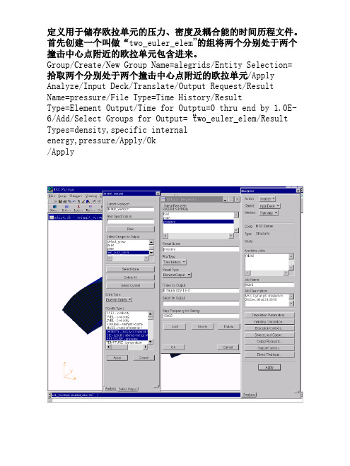
6.7 圆柱形钣金件冲压成形分析
有关工艺数据如下:
板料半径 板料厚度 凸模半径 凸模倒角半径 凹模内径 凹模倒角半径 冲压行程 冲压速度 压边圈内径 压边力 摩擦系数
100mm 0.7mm 50.0mm 13.0mm 51.25mm 5mm 40mm 4000mm/s 56.25mm 8.E8kN 0.18
数据文件产生后,用文本编辑器加以修改,将PATRAN界面中不支 持的卡片包含进来。
.
.
.
$
$ -------- Contact : master-slave-surface
$
$CONTACT
17 SURF SURF
1
2
+A012850
$+A012850
V4 BOTH
+A012851
$+A012851
[37 0 0]/Apply Point Coordinate List=
[50 13 0]/Apply Point Coordinate List=
[50 50 0]/Apply
Geometry/Create/Curve/Point/2Point/Starting Point List=Point 1/Ending Point List=Point 2/Apply /2D Arc2Point/Radius/Construction Plane List=Coord0.3/Arc Radius=13/Starting Point List=Point 2/Ending Point List=Point 3/Apply /Starting Point List=Point 3/Ending Point List=Point 4/Apply
patran使用技巧
分享patran使用中的一些技巧patran技巧[分享]为何我的FEM选单中不会出现Hybrid Mesh<Patran> 为何我的FEM选单中不会出现Hybrid Mesh?-->请在系统的环境变数中增加以下变数:PATRAN_USE_HYBRID_SURFACE_MESHER值设定为TRUE ,这样在surface mesh处, 除了Iso Mesh跟Paver Mesh外,就会看到另外一个Hybrid Mesh的选项[分享]MSC多解析任务批处理的方法如果仅有一台机器可以进行解析运算,有时候任务比较多的时候会时间来不及.提交模型让机器计算之后只能在旁边傻看着,什么也做不了. 其实有一种比较好一点的方法.可以用批处理文件让机器连续自动处理,下班时运行披处理文件,第二天早上来看结果.方法如下:比如有3个模型,S1.MOD,S2.MOD,S3.MOD1. 分别将上诉3个模型导出为DAT文件2.建立批处理c:\mscvn4w2002\solver\bin\nastran S1.datc:\mscvn4w2002\solver\bin\nastran S2.datc:\mscvn4w2002\solver\bin\nastran S3.dat3. 双击4. 下班5. 上班6. 导入解析结果.[转帖]PATRAN的一些小技巧1、在Patran里如何Move 一组Points 的位置, 而不改变这组Points 的ID 编号? Group/Transform/Translate的功能,这样不但编号不会变, 连property跟边界条件都会保留2、Patran如何执行多次Undo?所有Patran的操作步骤, 都记录在最新的一个patran.ses.xx中,如果需要多次undo, 可以刪除最后不需要的步骤指令行,再利用File -> Session -> Play 的方式, 执行改过的patran.ses.xx ,这样可以无限制的undo。
patran软件安装说明
软件安装说明By Zuo2009-12-3本说明主要针对水工专业常用的几种数值模拟软件,对他们的安装方法进行了详细的介绍与说明。
推荐按照下文中出现的先后顺序安装各种软件。
Patran:软件版本:Patran 2007 r2。
(不建议使用Patran 2005 r2,该版本属内部测试版本,与其他程序不兼容)安装文件:光盘镜像文件“m-patrr2.iso”。
安装方法:1、首先了解本计算机名,在“我的电脑——属性——计算机名”中的“完整的计算机名称”查找,为了后面安装的方便,在这里可以点击更改计算机名,建议取个简单的名字,例如myhost或xndss。
(注:更改后一定要重启。
)2、载入镜像文件,光盘自动弹出欢迎界面,点击Patran 2007 r2。
3、点选“next”N次。
注意:在选择安装目录的时候,最好就用它的默认目录,装在C盘较好。
4、装好后,在选择默认文件夹时直接点next就可以。
5、接着程序提示输入license文件。
我们先进入光盘,拷贝光盘下的MAGNiTUDE文件夹到C:\ MSC.Software 里面(默认),并将文件夹更名为license,打开该文件夹,用记事本程序打开license.dat 文件,其第一行应为:SERVER thishost 007330757468 1700将里面的”thishost”更改成本计算机名。
6、运行文件夹中的lmtools程序,点击Config Services选项卡,将里面的Service Name改为MSC,Path to the Imgrd.exe file 一项中浏览选择当前文件夹下的Imgrd.exe。
Path to the license file 一项中浏览中选择license.dat(文件类型选择.txt)。
Path to the debug log file 一项中浏览,并在文件名一栏中手动填入license.log。
7、勾选Use Services,并勾选Start Server at Power Up。
精典材料Patran的PCL用户手册V20
MSC.Patran PCL HandbookIn a Nutshell (7)What is PCL? (7)What can PCL be used for? (8)How does PCL work? (9)All you really need to know is on this page! (10)Documentation (10)PCL for Everyone (11)Entering Equations (11)Entering Data (12)Session Files (13)Rebuilding Models (14)PCL for the More Adventurous (17)Parametric Modeling (17)Adding a Graphical User Interface, GUI (21)Exercise 1: Session Files (22)PCL Programming Basics (24)Overview (24)PCL Expressions (26)Expressions, Comments, Syntax Tips (26)Identifiers (28)Naming Conventions (28)Variable / Function Scope (29)Structure of a PCL Function (30)Function Basics (30)Simple PCL function Example (31)Exercise 2: Hello World! (33)Exercise 3: Effective PCL (34)PCL Operators (35)String comparisons (35)PCL Variables and Constants (36)Datatypes (36)Variable Scope (37)Directly Allocated Arrays (38)Virtual arrays (39)Virtual strings (41)Loop Control Statements (42)For Loop (42)While Loop (42)Repeat Loop (43)BREAK (44)CONTINUE (45)Exercise 4: Writing Files (46)Exercise 5: Reading Files (48)Conditional Control Statements (49)IF Statement (49)SWITCH Statement (50)Structure of a PCL Function (51)Compiling and Linking PCL Functions (54)Primary PCL Directives (55)Compiling PCL outside of MSC.Patran (59)Linking Compiled Libraries (60)Other PCL Directives (61)Start Up Files (62)Exercise 6: p3epilog.pcl (63)Debugging (64)Debugging Compile Errors (64)Debugging Runtime Errors (65)Accessing PCL Functions (67)From The Command Line (67)From Any MSC.Patran Form (68)PCL Functions with Field Variables (69)MSC.Patran Built-In Functions (70)Naming Conventions for Applications (71)Naming Conventions for Other Operations (72)Exercise 7: Group Elements By Shape (74)Graphical User Interface (75)The PCL Class Statement (76)PCL Widgets (77)Required Functions for Building/Displaying a Form (78)The init() Function (78)The display() Function (79)Widget Callbacks (82)What Are They? (82)What Are They Used For? (83)Callback Arguments (Widget Function Data) (83)Widget Placement (85)Widget Variables (87)Modifying Widgets (88)Getting Data from Widgets (89)Putting it all Together (Example) (90)Exercise 8: Simple Form (92)The C-Preprocessor and Include Files (93)Make Files (94)Exercise 9: Callbacks (96)Handling Errors and Messaging (98)Errors from Built-In Functions (98)Custom Error Messages (99)Using User Messages Database (99)Without a Messages Database (100)Taking Advantage of the UNDO Feature (102)Select Mechanism (103)Select Mechanism GUI Mechanics (103)Select Databoxes, Select Frames, and Select Menus (103)GUI PCL Example (105)List Processor (106)List Processor Mechanics (106)All You Really Need to Know (107)Exercise 10: Form to Group Elms By Shape (110)Executing Programs Outside of MSC.Patran (112)Spawning Remote Processes (112)Locking a database (114)Using C and Fortran executables to access a MSC.Patran database directly. (115)External Access of an MSC.Patran Database (116)Special Widgets (118)File Widget (118)Spreadsheet Widget (121)Exercise 11: File Widget (122)Adding Help/Description to your PCL (123)Percent Complete (124)Functions (124)Example (124)Event Manager (125)General (125)Functions (126)Example (126)Primitive Graphics (127)Graphic Objects (127)Graphic Segments (128)Example (129)Another Example (130)Exercise 12: Primitive Graphics (131)MSC.Patran Customization (132)Adding Utility Programs to the Main Menu (132)Example (133)Example: p3_user_menu.my_menu.def (134)Customizing the MSC.Patran Toolbar (135)Exercise 13: Pulldown Menu (138)Exercise 14: Toolbar (139)Some Final Thoughts (141)Appendix A (144)Built-in Function Examples (144)Documentation for a typical MSC.Patran built-in function. (145)To get all the nodes and their global coordinates (146)To get the topology of every element (147)To get the shape of every element (148)To get all the element connectivity for all elements (149)To get the elements associated to a particular element property set (150)To get an element property value (shell thickness) for a specific element (151)To get a material property value (153)To get a list of all groups (154)To get the nodes and elements associated to the current group (154)To get result values for specified elements (155)Appendix B (164)Strings & String Functions (164)Declaration (165)Initialization (165)String Comparisons (165)Functions (166)Appendix C (174)Noteworthy Functions (174)sys_mov e_raw(...) (175)mth_array_search(...). (176)mth_sort(...) . (177)mth_sort_row(...).. (178)mth_sort_column(...) . (178)fem_geom_edge_length(...) .. (179)fem_geom_face_area(...). (179)fem_geom_elem_volume(...). (179)fem_geom_elem_location(...) .. (180)Appendix D (181)Form Spacing Parameters (appforms.p) (181)* SPACING (182)Appendix E (205)MSC.Patran Architecture (205)Appendix F (207)Shareware Compiling Functions (207)Appendix G (210)Parametric Patran (210)Appendix H (216)Additional List Processor Notes (216)List Processor Mechanics (217)List Processor Functions (217)List Processor Sublist Functions (219)List Processor Attribute Functions (220)Miscellaneous List Processor Functions (220)List Processor Examples (222)Easy to Use List Processor Functions (226)Appendix I (227)Key Mapping (227)Appendix J (230)Widget Classification (230)Appendix K (233)User Defined AOM (233)In a NutshellWhat is PCL?❑PCL stands for Patran Command Language❑Comprehensive, fully functional computer programming language❑Specifically and uniquely suited for MCAE applications ❑Delivered as a part of MSC.Patran❑Versatile and easy to useWhat can PCL be used for?❑Integrate application or site-specific programs with the MSC.Patran user interface and database❑Generate parametric/variational models for design/optimization ❑Integrate commercial and/or in-house analysis codes with MSC.Patran❑Display custom graphics❑Access the MSC.Patran database❑Create new and/or enhanced MSC.Patran functionality❑Database management for analysis files❑Eliminate tedious, repetitive proceduresHow does PCL work?❑All MSC.Patran commands are first interpreted by the PCL command interpreter❑PCL expressions are interpreted by a C program❑PCL functions can be compiled into libraries (more efficient binary representation) and “linked” with a MSC.Patran session❑“Built-in” PCL functions are written in C or FORTRAN❑MSC.Patran forms and menus can be created via PCL calls to Xlib, the X-window function library❑FORTRAN and C functions can be “linked” with MSC.Patran through PCLAll you really need to know is on this page! Documentation❑PCL and Customization - General programming guide for PCL.How to build forms, compile, manage libraries, access thedatabase, read/write files, etc.❑PCL Reference – Description of functions written to the session file.❑Develop: The MSC.Patran Toolkit – Documentation of additional functions for database access, etc.PCL for Everyone Entering EquationsUse of PCL when creating spatial fields:‘X + ‘X**2 –sinr(‘X)The PCL interpreter interprets anythingimmediately following a ‘ symbo l as afield variable as opposed to a PCLfunction, such as, sinr().Entering DataUse of PCL when entering geometric coordinates: [ `5./16.` 0 0 ]The PCL interpreter “evaluates” expressions enclosed in back tics, “`”.Other examples:[ `radius/length` 0 0 ]< `cosr(theta)` 1 1 >[ `MyFunction(radius)` 0 1 ]Session FilesSession and journal files are comprised entirely of PCL commands. Model changes (dimensions, mesh density, etc.) can be made quickly by editing and then replaying the session or journal files.$# Session file patran.ses.01 started recording at 16-Aug-01 14:33:54$# Recorded by: MSC.Patran 2001STRING asm_create_patch_xy_created_ids[VIRTUAL]asm_const_patch_xyz( "1", "<10 10 0>", "[0 0 0]", "Coord 0", @asm_create_patch_xy_created_ids )$# 1 Patch created: Patch 1STRING sgm_edit_surface_add_h_edit_ids[VIRTUAL]sgm_edit_surface_add_hole( 1, 1., TRUE, "", "[5 5 0]", "", "Surface 1", @sgm_edit_surface_add_h_edit_ids )$# 1 Surface Edited: Surface 1$# Session file patran.ses.01 stopped recording at 16-Aug-01 14:34:52Rebuilding ModelsThe following session file creates a trimmed surface, 10” x10”with a 1” diameter hole at the center. Note that the parameter that controls the diameter of the hole is indicated below.$# Session file patran.ses.01 started recording at 16-Aug-01 14:33:54$# Recorded by: MSC.Patran 2001STRING asm_create_patch_xy_created_ids[VIRTUAL]asm_const_patch_xyz( "1", "<10 10 0>", "[0 0 0]", "Coord 0", @asm_create_patch_xy_created_ids )$# 1 Patch created: Patch 1STRING sgm_edit_surface_add_h_edit_ids[VIRTUAL]sgm_edit_surface_add_hole( 1, 1., TRUE, "", "[5 5 0]", "", "Surface 1", @ sgm_edit_surface_add_h_edit_ids )$# 1 Surface Edited: Surface 1$# Session file patran.ses.01 stopped recording at 16-Aug-01 14:34:52In the session file below, the previous session file is edited to change the hole diameter from 1” to 4”$# Session file patran.ses.01 started recording at 16-Aug-01 14:33:54$# Recorded by: MSC.Patran 2001STRING asm_create_patch_xy_created_ids[VIRTUAL]asm_const_patch_xyz( "1", "<10 10 0>", "[0 0 0]", "Coord 0", @asm_create_patch_xy_created_ids )$# 1 Patch created: Patch 1STRING sgm_edit_surface_add_h_edit_ids[VIRTUAL]sgm_edit_surface_add_hole( 1, 4., TRUE, "", "[5 5 0]", "", "Surface 1", @ sgm_edit_surface_add_h_edit_ids )$# 1 Surface Edited: Surface 1$# Session file patran.ses.01 stopped recording at 16-Aug-01 14:34:52Session files can be executed or “played” by selecting File/Session/Play … from the top menu.PCL for the More Adventurous Parametric Modeling❑Session files can be parameterized by defining and using variables during the MSC.Patran session❑First, variables are declared and initialized via the MSC.Patran command lineSecond, the variables are used as input into the appropriate MSC.Patran forms (note the use of ` `, back tics)Upon application, the PCL interpreter evaluates `radius` (i.e., sets it equal to 1.0 in this example) and creates the curve. Note that the variable is passed to the session file in its unevaluatedBy using variables as parameters during MSC.Patran input, it is very easy to edit and change dimensions, mesh parameters, etc. in the session file.PCL for the more Adventurous Adding a Graphical User Interface, GUIThe next step might be to create a user interface to run the plate session file!Exercise 1: Session FilesUse MSC.Patran to create a parameterized session file that createsa rectangular surface with an arbitrarily located hole.1) Create variables for the dimensions shown below.2) Steps:a) Create variables using MSC.Patran’s command lineb) Create/Surface/XYZ (use variables length and width)c) Edit/Surface/Add Hole (use x_center, y_center, and diameter) Extra credit: Include error checking, i.e., it doesn’t make sensefor the hole to be outside the surface boundary.IF (x_center + diameter/2.0 > length) THEN RETURNExtra credit: Include meshing, boundary conditions, elementproperties, etc.Extra credit: Use ui_read_real(prompt) to enter the variablevalues interactivelyExtra credit: Turn your session file into a PCL FUNCTION.Exercise 1 Below is an image showing an MSC.Patran form allowing the interactive creation of the model for this exercise.NB – See Appendix G for notes about Parametric Patran.1) Variables and macros are defined interactively via a GUI2) Variables and macros are persistent3) Plus, more. See Appendix G for the detailsPCL Programming Basics Overview❑PCL is a full-featured programming language.❑Operators for arithmetic, relational, and string expressions.Examples include:❑Variables with type, scope, and dimension attributes INTEGER i, j, status, NodeIds(1000)LOGICAL flagREAL xyz(1000, 3), pressure(100), timeGLOBAL STRING my_group[32], all_groups[32](100)❑Dynamically allocated virtual strings and arraysINTEGER node_ids(VIRTUAL)STRING groups[32](VIRTUAL), MyString[VIRTUAL]❑Intrinsic functions for math, string manipulation, etc.sinr(angle)cosd(angle)mth_abs(MyVal)mth_sort(MyArray, CompactDuplicates, NumLeft)mth_array_search(MyArray, Look4, Sorted)str_length(MyString)str_substr(MyString, Position, SubStringLength)str_index(StringToSearchIn, StringToSearchFor)str_token(MyString, Delimiter, TokenNumber, [Compress])PCL Programming Basics ❑Loop control features, such as, WHILE, FOR, REPEAT, and LIST❑Conditional control structure, such as, IF-THEN-ELSE and SWITCH-CASE❑Subroutine (procedure) and function (command) calls❑Class grouping of related functions❑Read/write access to external ASCII and/or binary filestext_open(FileName, Options, 0, 0, FileId)text_read_string(FileId, InString, InStringLength)text_write_string(FileId, OutString)text_read(FileId, Format, MyIntegers, MyReals, MyChar)text_write(FileId, Format, MyIntegers, MyReals, MyChar)text_close(FileId, Options)file_exists(FileSpec, Options)file_delete(FileSpec)❑Access to MSC.Patran “built-in” functions that allow for direct access to the MSC.Patran database, geometry creation,drawing graphic primitives,db_count_nodes(NumNodes)db_get_node_ids(NumNodes, NodeIds)asm_const_grid_xyz(output_ids, coordinates_list, coord_frame, @created_ids)PCL Expressions Expressions, Comments, Syntax Tips❑Sample PCL expressions include:theta = 360.0 – MTH_ASIND(MyAngle)IF (radius >= 20.0) THEN radius = 20.0length = str_length(MyString)build_gear_geometry(30., 56., 3)❑PCL comments begin with a “/*” and end with a “*/”/*This is a comment.Look Ma, I’m making comments in PCL!Has anyone seen or heard from Elvis lately?*/a = 2 /* set mysterious factor equal to 2 */❑Alternatively, single line comments may begin with “$”$ Don’t you just hate to comment your programs?❑More than one PCL expression can co-exist on a line using a semi-colon, “;”alpha = 30.0; beta = 120.0❑PCL expressions can be continued on subsequent lines by using the “@” symbolui_wid_set(main_form, @“HEIGHT”, @NewHeight)ui_wid_set( /* widget_id */ main_form, @/* parameter */ “HEIGHT”, @/* value */ NewHeight)PCL Expressions ❑Don’t break expressions in the middle of a keyword, constant, or identifier❑Multiple blanks are the same as a single blank space❑Lines beginning with “!” (bang operator) are echoed to the xterm (UNIX) or command window (NT), but are not executedIn MSC.Patran type: !`i` nodes createdIn the xterm you see: %27 nodes created❑PCL expressions beginning with “>” are echoed to the session file❑PCL expressions can be typed directly into MSC.Patran at the command line❑PCL expressions may also be created with an editor in a text file and directed into MSC.Patran as a session file or by using the PCL directive !!INPUTIdentifiersNaming Conventions❑Function names and/or variable names are called identifiers ❑Can be up to 32 characters long❑Must begin with a non-digit❑Case insensitive (as is all of PCL)❑Cannot be a reserved keyword, i.e., FOR, IF, etc.❑Valid identifierscurrent_groupCurrentGroupMyString❑Invalid identifiersa_very_very_very_very_very_very_very_very_long_name 95abclistIdentifiers Variable / Function Scope❑Global variable names and functions share the same name space❑When two function names or two variable names conflict, the most recent addition supercedes the previous❑When function names and variable names conflict, the variable name takes precedence❑When compiling functions, PCL will indicate if a function name is superceded by writing “Cleared memory function” to thehistory window❑Hint: Use a unique prefix to keep function definitions separate,i.e au_do_this_and_that.pclStructure of a PCL Function Function Basics❑PCL functions begin with a FUNCTION statement and end with an END FUNCTION statement.❑The FUNCTION statement may contain an argument list to be passed in or out of the function.❑An optional RETURN statement can be used to return a calculated value from the function to the calling statement.❑Processing of the function terminates at either the END FUNCTION statement or a RETURN statement.❑There may be multiple RETURN statements within a single function.Simple PCL function Exampleanother_simple_function(29)$#My favorite number is 29$#My least favorite number is 13Sample output. The ui_write functions writetext to the history window, the session file(patran.ses.##), and the journal file(model.db.jou)Exercise 2: Hello World!Write and execute a PCL function that accepts a single real number argument and echoesHello World, my favorite number is ….to the MSC.Patran session file and history window.Your function will use either the ui_write(…),ui_writef(…), or ui_writec(…) functions.If you use the ui_writef(…) and ui_writec(…) functions, refer to the documentation for the correct format specifiers.Extra credit: How would this function change if you wanted to echo your favorite 10 numbers to the session file? Extra credit: How would this function change if you wanted to echo your favorite color to the session file?Exercise 3: Effective PCLWrite an essay on how the effective use of PCL could:a) Help create a lasting world peaceb) Eliminate world hungerc) Conquer the common coldd) Stop global warmingExtra credit: How could PCL be used to find Elvis?PCL OperatorsExamplesDist = mth_sqrt((x2-x1)**2 + (y2-y1)**2 + (z2-z1)**2) MyString3 = MyString2//”hijk”IF (a == b) THEN c = dIF (a == b && a == c) THEN ui_write(“Equilibrium”)x += 1 (this is equivalent to x = x +1)String comparisons❑The string comparison operators are special in that they ignore trailing blanks and uppercase and lowercase. Therefore, all of the following expressions are TRUE“ABC” == “ABC ““ABC” == “abc”❑Leading blanks are compared, i.e., “TEST” != “ TEST”❑To perform case sensitive comparisons use the str_equal() function, i.e.,IF (str_equal(GroupName1, GroupName2)) THEN RETURN 0PCL Variables and Constants Datatypes❑LOGICAL Boolean value: TRUE or FALSELOGICAL done, created31-1)❑INTEGER Value between +/- (2INTEGER i, num_nodes, node_id❑REAL Single precision floating value between 1.0E-30 and1.0E+30 (positive or negative)REAL x, y, z, force, pressure❑STRING Character string surrounded by double quotes, “Have you seen Elvis?”. Size or string length is defined with brackets, [ ]STRING FileName[80], GroupName[32]❑WIDGET Value is assigned by calls toUI_WIDGET_NAME_CREATE(…), used to create andmanipulate forms, etc.WIDGET main_form, MyButton, group_lboxVariable Scope❑GLOBAL Available to all functions during the MSC.Patransession❑LOCAL Default, only visible within the defining function ❑STATIC Same as LOCAL, but retains its value betweencalls❑CLASSWIDE Available to all functions in the CLASS andretains its value during the MSC.Patran sessionDirectly Allocated Arrays❑Directly allocated arrays can have any number of subscripts (dimensions), defined within parentheses ()❑Assigned upper and lower bounds, ArrayName(Lower:Upper)INTEGER MyArray(2:10)❑ Default lower bound is 1 (not 0) ❑ Available for all datatypes❑Row major (unlike Fortran which is column major)INTEGER MyArray(2, 3) = 1, 2, 3, 4, 5, 6❑Array dimensions are inherited from the argument list, i.e., PCL passes by reference❑Declaration ExamplesREAL displacements(6, 200) STRING group_names[32](20) INTEGER ids(0:2, 0:4, 0:10) LOGICAL exists(12)Virtual arrays❑Any variable can be defined as a VIRTUAL array instead of a directly allocated array. Virtual arrays do not have storagelocations assigned to them at program initialization. The size and amount of storage is allocated as requested and can bereused for other virtual arrays.❑To declare a virtual array, use the keyword VIRTUAL in place of the subscripts for the declaration, i.e.,REAL MyVals(VIRTUAL)INTEGER NodeIds(VIRTUAL)❑Storage is allocated using the function, sys_allocate_array(), or sys_allocate_array(MyVals, 1, 300)sys_allocate_array(MyVals, 1, 300, 1, 3)sys_allocate_array(MyVals, 1, 300, 1, 3, 0, 5)etc.❑Storage may be reallocated using the function,sys_reallocate_array(),sys_reallocate_array(MyVals, 1, 300, 1, 3)❑Storage may be freed using the function, sys_free_array(), sys_free_array(MyVals)Virtual array examplePCL Variables and Constants Virtual strings❑Any string variable can be defined as a VIRTUAL length string instead of a fixed length string. Virtual length strings do nothave storage locations assigned to them at programinitialization. The string length is allocated as requested and can be reused.❑To declare a virtual length string, use the keyword in place of the subscripts for the declaration, i.e.,STRING picklist[VIRTUAL]❑The string length is allocated using the sys_allocate_string() functionsys_allocate_string(picklist, 1000)❑The string length may be modified using thesys_reallocate_string() functionsys_reallocate_string(picklist, 2000)❑The string storage may be freed using the sys_free_string() functionsys_free_string(picklist)❑ A virtual length string can also be a virtual array, i.e., STRING picklists[VIRTUAL](VIRTUAL)Loop Control StatementsFor Loop❑SyntaxFOR (var=numeric_expr TO numeric_exprnumeric_expr label statements … END FOR❑ExampleAvgTemp = 0.0FOR (i = 1 TO NumNodes) AvgTemp += NodalTemp(i) END FORAvgTemp = AvgTemp/NumNodesWhile Loop❑SyntaxWHILE (logical_expression ) [label ] statements … END WHILE❑ExampleAvgTemp = 0.0 i = 1WHILE (i <= NumNodes)AvgTemp += NodalTemp(i) i += 1 END WHILEAvgTemp = AvgTemp/NumNodesRepeat LoopThis is similar to a WHILE Loop except that it will always be executed at least once. Only use REPEAT loops if you want to ALWAYS execute the loop at least once, otherwise us a WHILE loop.❑SyntaxREPEAT [label]statements …UNTIL (logical_expression)❑ExampleAvgTemp = 0.0i = 1REPEATAvgTemp += NodalTemp(i)i += 1UNTIL (i > NumNodes)AvgTemp = AvgTemp/NumNodesBREAKThe BREAK statement is used to exit a loop prior to its normal termination. It can be used in any of the loop statements.BREAK [❑END WHILE…❑Example 2 (nested loops, using labels)WHILE (i <= NumNodes) MainLoopWHILE (j <= 100) AnotherLoopWHILE (k <= 200) InnerLoopIF (status != 0) THEN BREAK MainLoopIF (status != 0) THEN BREAK AnotherLoopIF (status != 0) THEN BREAKIF (status != 0) THEN BREAK InnerLoopEND WHILEEND WHILEEND WHILECONTINUEThe CONTINUE statement is used to skip to the end of the loop ❑SyntaxCONTINUE [label]❑Example 1 (reading a text file)INTEGER file_id, lengthSTRING read_str[80]/* read grid information */WHILE (text_read_string(file_id, read_str, length) == 0)END WHILE❑Example 2 (nested loop, using labels)WHILE (i <= NumNodes) MainLoopREPEAT InnerLoopCONTINUE MainLoopBREAK InnerLoopCONTINUECONTINUE InnerLoopUNTIL (j > 1000)END WHILEstatements …Exercise 4: Writing FilesCreate a PCL function to write nodal data to a user-defined file. 1) The function should have a single argument, the filename to becreated, i.e., FUNCTION write_nodes_to_file(FileName)2) The data should be written to the file as a table, i.e.,Node Id x-coordinate y-coordinate z-coordinate3) Use virtual arrays4) Use the following built-in functions:db_count_nodes(NumNodes)db_get_node_ids(NumNodes, NodeIds)db_get_nodes(NumNodes, NodeIds, rcids, acids, NodeXYZ)text_open(FileName, Options, idum, idum, FileId)text_close(FileId, Options)text_write(FileId, Format, Ints, Reals, Chars)text_write_string(FileId, OutString)5) Use the documentation if you have questions about thearguments to the built-in functions.6) Think about your choice for the format argument in thetext_write(…) function. Will your file be comma or spacedelimited? Will it be fixed or free format?7) Sample code outline:a) Declare variablesb) Count nodes in the databasec) Allocate arraysd) Get node Idse) Get node coordinatesf) Open fileg) Write data to the file with a looph) Close filei) Be sure to include a message that the file output is completeWriting Files Extra credit: Include a header line at the top of the file thatincludes the filename and the total number of nodeswritten to the file.Exercise 5: Reading FilesWrite a function to read the file created in Exercise 4.1) The function should accept a single argument, i.e., the filenameto be read.FUNCTION ReadFile(FileName)2) Use the data in the file to create nodes with the following built-in function from the PCL Reference Manual:fem_create_nodes_1(RefCIDList, AnalysisCIDList, GeomFlag, @NodeIDList, XYZList, NodesCreatedList)3) Use the following built-in functions:text_open(FileName, Options, idum, idum, FileId)text_close(FileId, Options)text_read(FileId, Format, Ints, Reals, Chars)4) Sample code outline:a) Declare variablesb) Open the filec) Read the file within a loopd) Create new nodes as the file is read within the loope) Close the fileExtra credit: What if a node ID to be created already exists in the database?Extra credit: What if the file to be read doesn’t exist? Whatfunction can be used to determine if a file exists? Extra credit: Searching the documentation reveals anotherfunction that can be used to create nodes, i.e.,db_create_nodes(num_nodes, rcids, acids, xyz, group_id,node_ids, node_exists). Why might you use thisfunction versus fem_create_nodes_1(…)?Conditional Control Statements IF Statement❑SyntaxIF (logical_expression) THENstatements …ELSE IF (logical_expression) THENstatements …ELSEstatements …END IF❑ExampleIF (MyKeyWord == “CBAR” || MyKeyWord == “CBEAM”) THEN statements …ELSE IF (MyKeyWord == “CTRIA” || MyKeyWord == “CQUAD”) THEN statements …ELSE IF (MyKeyWord == “GRID”) THENstatements …ELSEstatements …END IF。
PATRAN NASTRAN R 傻瓜式图文安装过程全解

64位win7旗舰版操作系统下PATRAN2011+NASTRAN2011傻瓜式图文安装过程全解教程以64位Windows7旗舰版操作系统为例,给出PATRAN2011和NASTRAN2011的傻瓜式操作教程。
作者绝对不信还有比这个更详细的安装教程了……欢迎上传本教程到网络,帮助更多新手顺利安装PATRAN2011+NASTRAN2011……0 下载安装文件............................................................................................................................. - 2 -1 加载PATRAN CD2 ...................................................................................................................... -3 -2 生成PATRAN license文件......................................................................................................... - 4 -3 安装PATRAN license许可管理.................................................................................................... - 5 -4 确认license 是否可用 ............................................................................................................. - 10 -5 安装PATRAN 主程序................................................................................................................ - 12 -6 卸载PATRAN许可管理器.......................................................................................................... - 20 -7 生成NASTRAN licence文件....................................................................................................... - 22 -8 安装NASTRAN licence许可管理器........................................................................................... - 23 -9 安装NASTRAN主程序............................................................................................................... - 27 -10 设置NASTRAN域PATRAN的关联 .......................................................................................... - 34 -11 其他 .......................................................................................................................................... - 40 -0下载安装文件/topics/2916178//topics/2916179/注:下载的PATRAN2011 有三个文件夹,CD1 为32 位安装包,CD2 为64 系统安装程序,CD3 是帮助文档安装程序。
patran使用技巧

分享patran使用中的一些技巧patran技巧[分享]为何我的FEM选单中不会出现Hybrid Mesh<Patran> 为何我的FEM选单中不会出现Hybrid Mesh?-->请在系统的环境变数中增加以下变数:PATRAN_USE_HYBRID_SURFACE_MESHER值设定为TRUE ,这样在surface mesh处, 除了Iso Mesh跟Paver Mesh外,就会看到另外一个Hybrid Mesh的选项[分享]MSC多解析任务批处理的方法如果仅有一台机器可以进行解析运算,有时候任务比较多的时候会时间来不及.提交模型让机器计算之后只能在旁边傻看着,什么也做不了. 其实有一种比较好一点的方法.可以用批处理文件让机器连续自动处理,下班时运行披处理文件,第二天早上来看结果.方法如下:比如有3个模型,S1.MOD,S2.MOD,S3.MOD1. 分别将上诉3个模型导出为DAT文件2.建立批处理c:\mscvn4w2002\solver\bin\nastran S1.datc:\mscvn4w2002\solver\bin\nastran S2.datc:\mscvn4w2002\solver\bin\nastran S3.dat3. 双击4. 下班5. 上班6. 导入解析结果.[转帖]PATRAN的一些小技巧1、在Patran里如何Move 一组Points 的位置, 而不改变这组Points 的ID 编号? Group/Transform/Translate的功能,这样不但编号不会变, 连property跟边界条件都会保留2、Patran如何执行多次Undo?所有Patran的操作步骤, 都记录在最新的一个patran.ses.xx中,如果需要多次undo, 可以刪除最后不需要的步骤指令行,再利用File -> Session -> Play 的方式, 执行改过的patran.ses.xx ,这样可以无限制的undo。
patran学习-推荐下载

Introduction这篇文章我本人在学习patran/natran 过程中遇到的问题,及后来找到的解决方法,这篇文章也在逐步更新中,希望这篇文档能给那些学习用patran/nastran 的一点帮助。
Yuanchongxin Delft2011/10/3111. THE SOLUTION FOR THE RESIDUAL STRUCTURE AND THE APPLIED LOADS FOR THE CURRENT SUBCASE ARE ZERO.后来将边界条件由123456改为123,即将位移约束变成simplified supported,就没有此问题了。
2. USER WARNING MESSAGE 4124 (IFS3P)THE SPCADD OR MPCADD UNION CONSISTS OF A SINGLE SET 在图中用了RB3 的MPC,其中dependent node (ux,uy,uz), independent(ux,uy,uz,rx,ry,rz),有可能是这里的问题。
不过这个倒不影响计算结果。
3. 建立夹层结构的有限元网络对于meshing, sweep can produce the solid element on the basis of the shell element. 另外sweep 下的loft,可以在两个shell mesh 之间,创建solid element. 对于夹层结构的modeling, shell and solid element should share common node. 否则算出来的结果,solid stress 为零。
至于如何共用节点,则需用到element 下的sweep 命令。
4. No PARAM values were set in the Control File不管失败还是成功的f06 文件中,都会出现这句话。
PATRAN&NASTRAN(R2011)傻瓜式图文安装过程全解
64位win7旗舰版操作系统下PATRAN2011+NASTRAN2011傻瓜式图文安装过程全解教程以64位Windows7旗舰版操作系统为例,给出PATRAN2011和NASTRAN2011的傻瓜式操作教程。
作者绝对不信还有比这个更详细的安装教程了……欢迎上传本教程到网络,帮助更多新手顺利安装PATRAN2011+NASTRAN2011……0 下载安装文件............................................................................................................................. - 2 -1 加载PATRAN CD2 ...................................................................................................................... -3 -2 生成PATRAN license文件......................................................................................................... - 4 -3 安装PATRAN license许可管理.................................................................................................... - 5 -4 确认license 是否可用 ............................................................................................................. - 10 -5 安装PATRAN 主程序................................................................................................................ - 12 -6 卸载PATRAN许可管理器.......................................................................................................... - 20 -7 生成NASTRAN licence文件....................................................................................................... - 22 -8 安装NASTRAN licence许可管理器........................................................................................... - 23 -9 安装NASTRAN主程序............................................................................................................... - 27 -10 设置NASTRAN域PATRAN的关联 .......................................................................................... - 34 -11 其他 .......................................................................................................................................... - 40 -0下载安装文件/topics/2916178//topics/2916179/注:下载的PATRAN2011 有三个文件夹,CD1 为32 位安装包,CD2 为64 系统安装程序,CD3 是帮助文档安装程序。
Patran_PPT教程_第1章_简介
Modelname.db.jou
日志文件
记录从模型创建到目前的所有PCL命令。若数据库不慎删除,可根据日 志文件恢复。
Settings.pcl
偏好设置文件
ASCII文件。起动Patran会自动依据该文件设置Patran的环境变量。
p3epilog.pcl
ASCII文件,类似于DOS的autoexec.bat ,Patran起动时,自动执行该文 件。
作用:取消一个对象 方法:光标移到对象上,点右键
作用:循环选择 方法:按住shift,点右键
▲鼠标中键用法
▲按句法直接输入
▲ ▲几何编号
几何名称 点 关键字 Point 示 例 Point 1:24:3 Solid 55.3.1.1 线 Curve Curve 3 8 21 Surface 3.2 面 Surface Surface 1:200:2 Solid 10.2 体 向量 平面 坐标系 Solid Vector Plane Coord Solid 10:50:3 Vector 5 Plane 2 Coord 1.3 1号坐标系的z轴 意 义 1到24号点,间隔为3;即1,4, 7,10, 13,16,19,22。 55号实体第三面第一边1号顶点 3号,第8号,第21号曲线 3号面上的第2号边 1到100号面,间隔2 10号实体2号面 1到100号实体,间隔3
3. MSC.Patran用户界面风格
▲ Patran界面组成
Patran界面由Main Form ,Viewport 和Application Widget 组成 ▲ ▲ Main Form
▲▲▲ Menu Bar ◆ 包括File, Group,Viewport,Viewing,Display,Preference,Tools,Insight Control和Utilities(缺省不出现) ◆ 只影响全局性环境或共用操作,如视角,色彩,个人偏爱等 ◆ 与求解器及分析步骤无关 ▲▲▲ Application ◆由Geometry,Finite Element,Load/BCs,Materials,Properties,Fields,Load Cases,Analysis, Results,Insight和 X-Y Plot按钮组成
patran操作实例文档
2)读入分析结果:Action→Accese Results,Object→attach XDB,Method→Results Entities,Select Results File…→mode9-1.xdb,OK,Apply。 3.后处理,
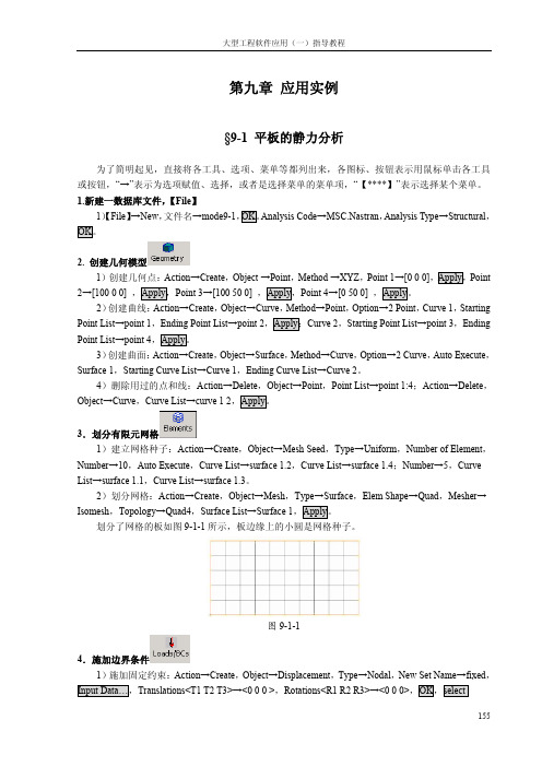
各阶模态的频率:在 Select Result Cases ቤተ መጻሕፍቲ ባይዱ,会列出结构的各阶频率,如图所示。
图9-1-2
5.定义各向同性的铝材料 1)定义材料:Action→Create,Object→Isotropic,Method→Manual Input,Material Name→
aluminium,Input Properties…,Constitutive Model→Linear Elastic,Elastic Modulus→70000,Poisson Ratio→0.3,OK,Apply。这里,创建了各向同性的铝材料,手工输入了杨氏模量和泊松比,对于各 向同性材料的静态分析,材料的独立弹性常数只有两个,也不必输入材料的密度值。
8.后处理, 1)显示位移云纹图:Action→Create,Object→Quick Plot,Select Result Cases→Default Static
Subcase,Select Fringe Result→Displacements Translational,Quantity→Magnitude,Apply。此时,平 板模型的位移云纹图就显示出来,如图 9-1-3 所示。
Patran操作中文手册

Patran 操作中文手册欢迎同行来论坛进行交流科研中国收集整理版权归原作者所有科研中国翱翔论坛/bbs翱翔科技服务中心 2005年8月17日制作目录课程1. 入门课程2. 从IGES文件输入几何体课程3. 连柄的几何模型课程4. U形夹的三维几何模型课程5. U形夹的三维视图课程6. 显示练习课程7. U形夹的三维有限元模型课程8. 另一种U形夹的三维有限元网格课程9. 验证及属性设置课程 10. 随空间和时间变化的载荷课程 11. 在三维U形夹上加载荷和边界条件课程 12. 定义材料特性课程12a. 用材料选择器获得材料特性课程 13. 与空间相关的物理特性课程 14 . 静态分析的建立课程 15. 组群和列表的使用课程 16. 位移结果的后处理课程 17. 应力结果的后处理课程 18. 瞬态响应结果的后处理课程 19. 后处理透视图课程 20. 瞬态和模态的动画课程 21. 与时间相关的结果课程 22. 将PATRAN2.5的模型输入到PATRAN 3 中课程 4. U形夹的三维几何模型目的:生成一个新的数据库生成几何体改变图形显示模型描述:本练习是通过MSC/PATRAN的点、线、面、体建立一个几何模型, 熟悉PATRAN 的几何建模过程,模型的几何尺寸见下图。
练习过程1.新生成一个数据库并命名为clevis.dbFile/New Database…New Database Name clevis.dbOKNew Model PreferenceTolerance DefaultOK2. 把几何参数选择改为PATRAN 2方式。
PATRAN 2 Convention 代表着一个特点的参数化几何类别。
这个操作可以使用户产生一个几何体,该几何体可以通过PATRAN 2的中性文件和IGES文件输入或输出到PATRAN 3中。
Preference/Geometry…Geometric Representation Patran 2 ConventionSolid Origin Location P3/PATRAN ConventionApplyCancel3. 生成一个位于U形夹孔内半径上的点。
Patran教程工况及边界条件PPT教案

300
若 T300=1,300=add, T200=1,则TB=5000C
可变动LBC 的Scale Factor:分析及作用区域相同,仅数 值大小不同,只需改动LBC缩放系数,不需定义多个LBC
示例
第7页/共8页
工况
工况中边界条件的优先权(Priority)
问题:热分析中,AB边添加了
D
C
3000C的恒温条件(T300),BC边添
加2000C的恒温条件(T200),问结点
200
B处边界条件是多少?300℃,
200若℃或T30500=0℃1, ?T200=2, 则TB=3000C
A
B
若 T300=2, T200=1, 则TB=2000C
Patran教程工况及边界条件
会计学
1
3.施加步骤
patran安装说明补充
patran安装说明补充patran2021+nastran2021安装(我是win7旗舰版32位系统)都是iso文件,使用虚拟光驱daemontoolslite打开安装方法如下:2.新建环境变量,计算机右键属性->(左边栏)高级系统设置->高级->环境变量->用户变量->新建->变量名为“lm_license_file”。
变量值为“1700@计算机名”,比如说我的计算机名就是\局部变量就是1700@abc。
计算机名可以从右键计算机属性中搜到。
3.生成license.dat文件。
(光驱盘符假设为g)将g(patran2021):\\magnitude下的msc_calc.exe文件拷贝到任意目录,推荐放在桌面上,运行msc_calc.exe,会在当前目录下生成一个license.dat文件。
这个文件备用。
4.加装licensing。
运转g(patran2021):\\magnitude目录下的msc.licensing_11.6_windows.exe,当被问到挑选一个license文件的时候挑选出上一步分解成的license.dat文件,稳步直至顺利完成。
特别注意:a右键以管理员身份安装license以及软件!b在加装license时,提示信息你的hostid时特别注意比对其与否与a中揭发的物理地址一致!若不一致,可能将就是无线网络的mac地址而非本机的mac地址,此时须要停止使用无线网络,再重新安装licensec检查license目录下的license.dat文件第一行与否为:serve计算机名物理地址17005.证实license与否需用以及“服务”与否关上。
从开始菜单中找出刚才加装的msc.software>msc.licensing11.6中的flexlmconfigurationutility,打开,点取configservices标签,把最下面的startserveratpowerup和useservices点上勾,再点取saveservices。
patran从入门到精通
patran从入门到精通patran从入门到精通MSC.PATRAN&MSC.NASTRAN使用指南北京.BUAA2002.05.111Τ目录第1章MSC.Software及MSC.Patran介绍1.1 MSC.Software 公司介绍1.2 什么是 MSC.Patran1.2.1 开放式几何访问及模型构造1.2.2 各种分析的集成1.2.3 有限元建模1.2.4 分析条件定义1.2.5 结果交互式可视化后处理1.2.6 高级用户化工具??PATRAN-PCL命令语言 1.3 MSC.Patran 的一般使用流程1.4 MSC.Nastran介绍1.4.1 静力分析1.4.2 曲屈分析1.4.3 动力学分析1.4.4 非线性分析1.4.5 热传导分析1.4.6 空气动力弹性击颤振分析1.4.7 流-固耦合分析1.4.8 多级超单元分析1.4.9 高级对称分析1.4.10 设计灵敏度及优化分析1.5 MSC.Patran和 MSC.Nastran的安装1.5.1 MSC.Patran的运行环境1.5.2 MSC.Patran和 MSC.Nastran的安装过程1.6 与 MSC.Patran和 MSC.Nastran相关的主要文件1.7 本章小结2Τ第2章建立几何模型(Geometry)2.1 Patran的用户界面及其操作特点2.1.1 Patran的用户界面2.1.2 Patran 中 Application Widget面板的操作特点2.2 建立几何模型2.2.1 Geometry介绍2.2.2 创建点(Point)2.2.3 创建曲线(Curve)2.2.4 创建曲面(Surface)2.2.5 创建实体(Solid)2.2.6 建立自己的坐标系(coord)2.2.7 创建平面和矢量(Plane &Vector)2.3 编辑几何模型2.3.1 编辑点(Point)2.3.2 编辑曲线(Curve)2.3.3编辑曲面(Surface)2.3.4 编辑实体(Solid)2.4 输入输出几何模型(Import & Export)2.4.1 输入几何模型2.4.2 输出几何模型2.4.3 修复损坏文件的一种方法2.5 其它几何操作2.5.1 删除(Delete)2.5.2 显示信息(Show)2.5.3根据以有几何对象创建新的几何对象(Transform)2.5.4 检查(Verify)2.5.5 联结(Associate)2.6 本章小结3Τ第 3章有限元网格划分(Element)3.1 Element介绍 3.1.1 Element介绍3.1.2 MSC.Patran中的单元库3.2 直接生成有限元网格(Create)3.2.1 自动网格生成器的分类及其使用范围3.2.2 网格疏密的控制3.2.3 网格自动生成的操作过程3.2.4几何协调性与有限元网格的协调性3.3 用别的方法生成有限元网格(Transform、Sweep)3.3.1 移动、旋转、镜像(Transform)3.3.2 拉伸、滑动(Sweep)3.4 手工生成有限元网格(Create)3.4.1 手工创建节点3.4.2 手工生成单元3.4.3 创建超单元3.4.4 多点约束(MPC)3.5 对节点、网格或多点约束进行修改(Modify)3.5.1 编辑修改网格3.5.2 编辑修改单元3.5.3 编辑修改梁/杆单元3.5.4 编辑修改三角形单元3.5.5 编辑修改四边形单元3.5.6 编辑修改四面体单元3.5.7 编辑修改节点3.5.8 编辑修改网格种子3.5.9 编辑修改多点约束3.6 对模型进行检查(Verify、Equivalence) 4Τ3.6.1 检查模型(Verify)3.6.2 消除重复节点(Equivalence) 3.7 其它操作(Renumber、Associate、Disassociate、Optimize、Show、Delete)3.7.1 重新标号(Renumber)3.7.2 联结(Associate)3.7.3 反联结(Disassociate) 3.7.4 优化(Optimize)3.7.5 显示信息(Show)3.7.6 删除(Delete)3.8 网格划分示例 3.9 本章小结第 4章有限元模型的载荷及边界条件(Loads/BCs)4.1 Loads/BCs介绍4.2 施加边界条件(Create)4.3 显示、检查边界条件(Show Tabular、Plot Contours、Plot Markers)4.3.1 以表格方式显示边界条件(Show T abular)4.3.2 以云纹图方式显示边界条件(Plot Contours)4.3.3 以图符形式显示边界条件(Plot Markers)4.4 修改及删除边界条件(Modify、Delete)4.4.1 修改边界条件(Modify)4.4.2 删除边界条件(Delete)4.5 施加载荷的一个例子4.6 本章小结第5章材料(Materials) 5.1 Material介绍5.2 创建材料模型(Create)5.2.1 创建各向同性材料(Isotropic)5.2.2 创建 2D正交各向异性材料(2d Orthotropic)5Τ5.2.3 创建 3D正交各向异性材料(3d Orthotropic)5.2.4 创建 2D各向异性材料(2d Anisotropic)5.2.5 创建 3D各向异性材料(3d Anisotropic)5.2.6 创建复合材料(Composite) 5.3 显示创建的材料模型信息(Show) 5.4 修改及删除创建的材料模型(Modify和 Delete)5.4.1 修改材料属性(Modify)5.4.2 删除已定义的材料(Delete) 5.5 一些使用技巧5.5.1 创建自己的材料库 5.5.2 Material Selector的使用 5.6 本章小结第6章有限元模型单元的物理特性(Properties) 6.1 Properties介绍6.2 创建物理特性并施加于单元(Create) 6.2.1 创建0D单元的物理特性6.2.2 创建 1D单元的物理特性6.2.3 创建 2D单元的物理特性6.2.4 创建 3D单元的物理特性6.3 显示物理特性(Show)6.4 修改单元的物理特性(Modify)6.5 删除单元属性(Delete)6.6 本章小结第7章进行分析(Analysis)7.1 Analysis介绍7.2 分析参数的设定及提交分析运算(Analyze) 7.2.1 转换参数设置(Translation Parameters)7.2.2 分析类型的设置(Solution Type) 6Τ7.2.3 直接文本输入(Direct Text Input) 7.2.4 Subcase的定义(Subcase)7.2.5 选择定义好的 Subcase(Subcase Select) 7.3 读入分析结果(Read Output2、Attach XDB) 7.3.1 读入分析结果(Read Output2) 7.3.2 将计算结果与Patran相关联(Attach XDB) 7.4 分析模型的优化(Optimize)7.5 读入 Nastran的输入模型(Read Input File) 7.6 删除分析工作(Delete)7.7 本章小结第8章后置处理(一)(Results)8.1 Results介绍 8.1.1 结果的定义 8.1.2 Results的功能和限制8.1.3 Results的一般使用方法8.2 Results中各种后处理方法介绍(Create) 8.2.1 分析结果的快速显示(Quick Plot) 8.2.2 创建结构变形图(Deformation) 8.2.3 创建云纹图显示(Fringe)8.2.4 图形符号显示(Marker)8.2.5 创建 YX坐标曲线图(Graph)8.2.6 创建动画(Animation)8.2.7 生成报告(Report)8.2.8 已有结果再处理(Results)8.2.9 自由体后置处理(Freebody)8.3 Results后处理其它操作(Modify、Plot、Delete)8.3.1 修改显示或报告(Modify)8.3.2 显示创建的各种图形(Post)7Τ8.3.3 删除处理结果(Delete)8.4 本章小结第9章后置处理(二)(Insight) 9.1 Insight介绍9.1.1 Insight中的工具9.1.2 Insight的一般使用步骤9.2 创建 Insight工具9.2.1 创建等值面(Isosurface) 9.2.2 其它工具方法的属性设置(Attributes) 9.2.3 Insight Control菜单的使用9.3 修改和删除已创建的显示工具(Modify、Delete) 9.3.1 修改已创建的显示工具(Modify) 9.3.2 删除已创建的显示工具(Delete) 9.4 本章小结第 10章不同工况的处理(Load Cases) 10.1 工矿介绍(Load Case)10.2 创建及修改工况10.2.1 创建工况(Create) 10.2.2 修改工况(Modify)10.3 显示工况(Show)10.4 删除工况(Delete)10.5 本章小结第 11章场(Fields)11.1 Fields介绍11.2 创建场(Create)11.2.1 创建空间场(Spatial Field) 11.2.2 创建材料属性场(Material Field)11.2.3 创建非空间场(Non-spatial Field)8Τ11.3 修改、显示和删除场11.3.1 修改场(Modify)11.3.2 显示场(Show)11.3.3 删除场(Delete)11.4 本章小结第 12章 XY坐标曲线图管理(XY Plot) 12.1 创建(Create)12.1.1 创建 XY窗口12.1.2 创建曲线12.1.3 创建曲线图的标题12.2 显示(Post)12.2.1 显示窗口12.2.2 显示曲线12.2.3 显示标题12.3 修改(Modify) 12.3.1 修改 XY窗口12.3.2 修改曲线12.3.3 修改曲线图的标题 12.3.4 修改坐标轴的属性 12.3.5 修改图例12.4 重命名(Rename) 12.5 删除(Delete) 12.6 本章小结第 13章 Patran的菜单项 13.1 文件管理(File) 13.1.1 数据库文件基本操作 13.1.2 Utilities菜单项 13.1.3 模型的输入输出 9 Τ13.1.4 其它文件操作 13.1.5 关闭 Patran 13.2 组(Group)13.2.1 创建组(Create)13.2.2 显示组(Post)13.2.3 修改组(Modify)13.2.4 移动/拷贝到组(Move/Copy) 13.2.5 设为当前组(Set Current)13.2.6 由已有的组创建对象(Transform) 13.2.7 删除组(Delete)13.2.8 将命名属性应用于组(Attributes) 13.3 视窗管理(Viewport)13.3.1 创建视窗(Create)13.3.2 显示视窗(Post)13.3.3 修改视窗的属性(Modify)13.3.4 删除视窗(Delete)13.3.5 同时显示所有的视窗(Tile)13.4 视图操作(Viewing)13.4.1 移动、旋转和缩放(Transformations) 13.4.2 模型居中(Fit View)13.4.3 鼠标定位显示(Select Center) 13.4.4 选择局部显示(Select Corners) 13.4.5 缩放视图(Zoom% of View) 13.4.6 视点角度(Angles)13.4.7 用两点确定视角(View From/T o)13.4.8 各方向不同比例缩放(Scale Factors) 13.4.9 命名视图(Named View Options) 13.4.10 切割/投影显示(Clipping/Perspective) 10Τ13.4.11 任意面切割(Arbitrary Clipping) 13.5 图形显示特性设置(Display)13.5.1 实体的颜色、标签和渲染设置(Entity Color/Label/Render)13.5.2 显示/不显示(Plot/Erase)13.5.3 高亮度显示(Highlight)13.5.4 几何对象显示控制(Geometry)13.5.5 有限元对象显示控制(Finite Element) 13.5.6 边界条件及单元属性显示控制(Load/BC/Elem. Props)13.5.7 命名属性(Named Attributes) 13.5.8 坐标系(Coordinate Frames) 13.5.9 视窗标题(Titles)13.5.10 参考彩色谱(Spectrums)13.5.11 范围(Ranges)13.5.12 视窗背景颜色设置(Color Palette) 13.5.13 光线设置(Shading)13.5.14 光源(Light Sources)13.6 环境设置(Preferences)13.6.1 分析解算器的选择(Analysis) 13.6.2 全局参数设置(Global)13.6.3 显示设置(Graphics)13.6.4 鼠标设置(Mouse)13.6.5 选择设置(Picking)13.6.6 报告格式设置(Report)13.6.7 几何设置(Geometry)13.6.8 有限元设置(Finite Element) 13.7 工具选项(Tools)13.7.1 列表选择(List)13.7.2 计算质量(Mass Properties) 11Τ13.7.3 定义梁截面(Beam Library) 13.7.4 定义变量(Model Variables) 13.7.5 设计优化(Design Study) 13.7.6 ABAQUS的“Rebar”定义(Rebar Definition) 13.7.7 调用MSC.Fatigue应用模块(MSC.Fatigue) 13.7.8 层合板设计(Laminate Modeler) 13.7.9 分析管理器(Analysis Manager) 13.7.10 关于网格划分等的补充功能(Pre Release) 13.8 在线帮助(Help)13.9 本章小结第 14章应用实例14.1 静力分析14.2 模态分析14.3 复合材料结构分析14.4 非线性分析14.5 热应力分析14.6 优化分析14.7 本章小节附录A MSC.Patran中数据的输入方法附录B Patran各工具栏工具功能列表附录C Patran中的单位制附录D Patran、Nastran中的坐标系附录E MSC的工具集Utilities 12 Τ第 1章 MSC.Software及 MSC.Patran 介绍MSC.Software(MSC.Software Corporation,或写作 MSC)公司是世界著名的有限元分析和计算机仿真预测应用软件CAE) 供应商之一,其所提供的产品从专为设计工程师校核设计概念而开发的桌面级设计工具,到以完成各类大型复杂工程分析的企业级软件平台,产品的应用范围非常广泛,包括航空、航天、汽车、船舶、电子、核能等,涉及内容包括结构设计、静态分析、动态分析、热传导分析、疲劳、运动模拟等,其产品为世界众多著名大公司使用。
patran培训教材(有限元分析)
目录第一章 Patran基础知识 (2)第二章悬臂梁的有限元建模与变形分析 (12)第三章受热载荷作用的薄板的有限元建模与温度场求解 (20)第四章带孔平板的受力分析(平面) (23)第五章厚壁圆筒的受内压作用时的应力分析 (27)第六章受压力载荷作用时板的受力分析 (31)第七章板的模态分析 (34)第八章板的瞬态响应分析 (37)第九章板的频率响应分析 (41)第十章提取车架中性面的模态分析 (44)第一章 Patran 基础知识一.Patran 的用户界面介绍Patran 具有良好的用户界面,清晰、简单、易于使用且方便记忆,其用户界面如图1—1所示。
图1—1 patran 界面按照各部分的功能,可将Patran 界面划分为四个区域:菜单和工具栏区、操作面板区、图形编辑区、信息显示和命令行输入区。
下面,就分别对这几个区域进行介绍。
1。
菜单和工具栏区如图1-2所示,patran 的界面上有一行菜单,两行工具栏。
图1-2 菜单工具栏Patran 的菜单是该软件的重要组成部分,使用菜单项,可以完成多设置和操作。
本来,菜单与各种工具是配合使用的,两者是不能独立区分的。
这里对菜单栏进行简单的介绍,一般情况下,Patran 有九个主菜单项,如图1-2所示,文件管菜单栏应用菜单按钮工具栏理(File)菜单主要用于Patran数据库文件的打开/关闭,同时也用来从其他CAD系统输入模型;组(Group)菜单主要用于组的操作,作用类似CAD系统中的“层";视窗管理(Viewport)菜单用于视窗设置;视图操作(Viewing)菜单用于图形显示设置,包括了工具栏中一些工具的功能;元素显示管理(Display)菜单用于设置各种元素的显示方式;参数设置(Preferences)菜单用于选择求解器,定制用户自己的环境等操作;工具选项(Tools)菜单中提供了许多非常有用的工具;在线帮助(Help)菜单为使用者提供在线帮助.工具栏各工具功能见表一:表一 Patran工具栏各工具功能列表2。
patran操作实例文档

158
大型工程软件应用(一)指导教程
2.进行模态分析, 1)进行分析:Action→Analyze,Object→Entire Model,Type→Full Run,Job Name→plate_static,
Translation Parameters…,Data Output→ XDB and Print,OK,Solution Type…→NOMAL MODES, OK,Apply。
图 9-2-1 1)显示三阶模态(2弯):Action→Create,Object→Quick Plot,Select Result Cases→Default Mode 3:Freq.=48.895,Select Fringe Result→Eigenvectors Translational,Quantity→Magnitude,Select Deformation Result→Eigenvectors Translational,Apply。则会显示出平板结构的位移变形和变形的云 纹图,如图9-2-2所示。
划分了网格的板如图 9-1-1 所示,板边缘上的小圆是网格种子。
图 9-1-1
4.施加边界条件 1)施加固定约束:Action→Create,Object→Displacement,Type→Nodal,New Set Name→fixed,
Input Data…,Translations<T1 T2 T3>→<0 0 0 >,Rotations<R1 R2 R3>→<0 0 0>,OK,select
大型工程软件应用(一)指导教程
第九章 应用实例
(完整版)patran静力学分析操作
课程 14. 静态分析的建立目的:⏹回顾建立一个模型的全部必要步骤。
⏹懂得如何用MSC/PATRAN进行静态分析。
模型描述:在本练习中,将建立完整的MSC/PATRAN主框架模型,并用MSC/NASTRAN进行相应静态分析。
图14—1具有网格控制点的四分之一对称模型。
图14-2表14-1单元类型:四边形单元Quad8单元总体边界长度: 1.0”材料常数描述:名称: Steel弹性模量,E(psi): 29E6泊松比,ν: 0。
30线弹性各向同性材料单元特性:名称: Prop1材料: Stee1厚度: 0。
2”分析代码: MSC/NASTRAN分析类型:完全线性静态分析分析求解参数: 线性静态。
分析翻译器:文本输出 2(Text Output 2)格式.分析输出项:位移、单元应力、单元应变能建议的练习步骤:⏹生成新的数据库并命名为Plate_hole.db。
⏹把Tolerance设为Default,Analysis Code设为MSC/NASTRAN。
⏹产生四分之一对称模型,用图14-2和表14—1的数据来划分有限元网格。
⏹等效并优化整个模型,校验是否所有单元的法向方向相同。
⏹根据表14-1定义材料特性和单元特性。
⏹对全部单元的上表面施加不均匀压力Pressure1。
⏹在模型适当位置载加位移边界条件。
把模型上下左右边界的位移约束分别命名为disp_lf, disp_rt, disp_tp和disp_bt。
⏹根据表14—1,为把模型用于分析运行做准备。
练习过程:1.生成新的数据库并命名为Plate_hole。
db。
File/New Database。
.。
New Database Name Plate_hole。
dbOK2.把Tolerance设为Default,Analysis Code设为MSC/NASTRAN. New Model PreferenceTolerance DefaultAnalysis Code: MSC/NASTRANOK3。
Patran操作步骤仅供参考,照搬的切小JJ
3.1.1创建数据库文件1)任务栏中点【File】,选择New,文件名输入yuan,点。
2)会出现如图3-1这样的一个选择项,Analysis Code下选项选择MSC.Nastran,Analysis Type下的选项选择Structural,点。
图3-1 创建文件选择区3.1.2创建几何模型1)任务栏中点【Geometry】,Action→Create,Object→Solid,Method→Primitive,点击按钮,弹出如图3-2所示菜单:图3-2 创建平板菜单栏2)设定长宽高X Length list→60, Y Length list→40, Z Length list→1, 选择基点Base Origin Point List→[-30 -20 0],点,得到如图3-3所示平板。
图3-3 创建平板3)创建圆柱:点击按钮,出现如图3-4所示菜单:图3-4 创建圆柱菜单栏4)设定圆柱高Height List→5,半径Radius List→2,基点Base Origin Point List →[0 0 0],点。
得到如图3-5所示模型:图3-5 带圆柱板5)【Geometry】菜单栏中,Action→Edit,Object→Solid,Method→Boolean,点击按钮,弹出如图3-6所示菜单:图3-6 Boolean菜单6)选中Target Solid下的命令框,左键单击平板,选中Subtracting Solid List 下命令框,左键单击圆柱,点,得到图3-7所示带圆孔板:图3-7 带圆孔板模型3.1.3有限元网络划分1)任务栏中点【Meshing】,Action→Create,Object→Mesh,Type→Solid,弹出如图3-8所示菜单:图3-8 有限元网络划分2)这里我们选用四面体自动划分网格Elem Shape→Ted, Mesher→TetMesh, Topology→Ted4, Input List→Solid 1,取消Automatic Calculation选项前的√,在Value后的命令框中输入1.0,点,得到图3-9模型。
- 1、下载文档前请自行甄别文档内容的完整性,平台不提供额外的编辑、内容补充、找答案等附加服务。
- 2、"仅部分预览"的文档,不可在线预览部分如存在完整性等问题,可反馈申请退款(可完整预览的文档不适用该条件!)。
- 3、如文档侵犯您的权益,请联系客服反馈,我们会尽快为您处理(人工客服工作时间:9:00-18:30)。
e b c g f
PAT302, Workshop 19, June 2003
WS19-6
Step 2. Create a Group for Global Model
a
Create a group and make it current for the global model as follows. a. Group : Create… b. Enter global_loads_model for New Group Name. c. Select the Make Current and Unpost All Other Groups icons. d. Click on Apply. e. Click on Cancel.
PAT302, Workshop 19, June 2003
WS19-5
Step 1. Create a New Database
a
d
Open database. a. File : New. b. Enter quarter_plate for File Name. c. Click OK. d. Under New Model Preferences, select Based on Model Tolerance. e. Select MSC.NASTRAN for Analysis Code. f. Select Structural for Analysis Type. g. Click on OK.
b e f
g d c h
PAT302, Workshop 19, June 2003
WS19-11
Step 6. Use Analysis to Read Model for Local
Select the input file to read into the input deck. a. Click on Select Input File.. b. Select panel.bdf for Select File. c. Click on OK. d. Click on Apply. e. Click OK for the Nastran input file summary.
PAT302, Workshop 19, June 2003
WS19-4
Suggested Exercise Steps (continued)
15. 16. 17. 18. 19. 20. 21. 22. 23. 24. 25.
Create a Loads/BCs for the local model. Post and make current the group for the local model. Create a uniform pressure for the local model. Create a MSC.Nastran input file for analysis of local model. Run MSC.Nastran. Access results. Post process results. Create a viewport so have one for each model. Post both global and local model. View the results for each model simultaneously. Quit MSC.Patran.
Note that the viewport is cleared
b c
d
e
WS19-10
PAT302, Workshop 19, June 2003
Step 6. Use Analysis to Read Model for Local
a
Under, Analysis, read in a MSC.NASTRAN input deck that represents the detailed panel stress model. a. Analysis : Read Input File / Model Data / Translate. b. Click on Entity Selection… c. Click on Define Offsets… d. Enter 1000 for Input Offset Value in the Nodes row and press the Enter key. e. Enter 1000 for Input Offset Value for the Elements row and press the Enter key. f. Click on OK. g. Click on OK.
WORKSHOP 19 GLOBAL/LOCAL MODELING USING FEM FIELDS
PAT302, Workshop 19, June 2003
WS19-1
PAT302, Workshop 19, June 2003
WS19-2
Problem Description
This exercise is used to demonstrate how to map displacement results from the analysis of a global(overall) model onto the perimeter of a local(detail/ component of overall) model. The local model is used for an analysis to obtain results for the detail/component. The global model and its results are read into an MSC.Patran database. The results are used in the creation of a vector FEM field. The FEM field is used to map the global model displacement results onto the local model perimeter. Also, a pressure load is applied to the local model. An analysis of the local model is performed. The displacement results for both global and local models are compared.
PAT302, Workshop 19, June 2003
WS19-3
Suggested Exercise Steps
1. 2. 3. 4. 5. 6. 7. 8. 9. 10. 11.
12. 13. 14.
Open a new database. Create a group for the global model. Use analysis form to read model and results for global model. Turn off all labels and reset the view to an isometric view. Create a group for the local model. Use analysis form to read local model. Post only the group for the global model for displaying its results. Display the deflections and stresses of the global model. Set the displacements to true scale 1.0. Create a vector plot of displacements for the global model. With the vector plot displayed, create a continuous, spatial, Vector FEM field using the global displacements. Post only the detailed local panel model. Create a group to be used for creating LBCs for the local model. Create a load case for the local model LBCs.
b c
d
PAT302, Workshop 19, June 2003 WS19-7
e
Step 3. Use Analysis to Read Model/Results for Global
a
Use Analysis to read in both the model and results of the Global Loads Model. a. Analysis : Read Output2 / Both / Translate. b. Click Select Results File… c. Select multi_cell_box.op2 for Select File. d. Click on OK. e. Click on Apply.
PAT302, Workshop 19, June 2003
WS19-9
Step 5. Create a Group for Local Model
a
Create another group, making it current, called panel_model. a. Group : Create… b. Enter panel_model for New Group Name. c. Select the Make Current and Unpost All Other Groups toggles. d. Click on Apply. e. Click on Cancel.
