派克系列高清数字混合矩阵
Parker Hannifin Corporation 高速自动化系列 HLE-Z 系列线性模块说明
Typical Applications
As part of advanced, cost-effective construction of machines and handling systems:
• Materials handling: palletization, depalletizing, feeding, part removal
Irwin, Pennsylvania
Catalog 8092/USA
Linear Modules
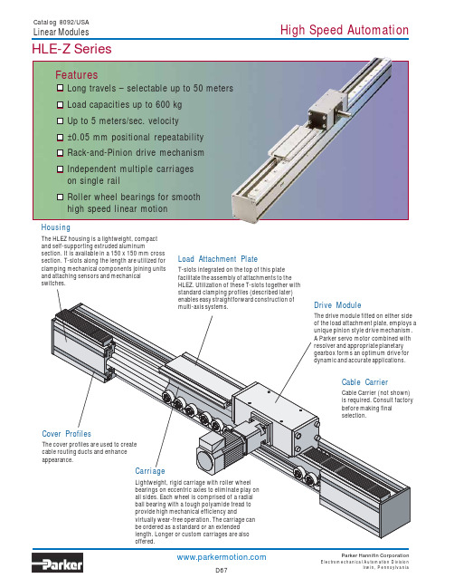
HLE-Z Series
The “endless” linear unit is designed for guiding, transporting or positioning payloads over long travel distances with high rigidity and accuracy. This is accomplished by incorporating Parker’s uniquely designed rack-andpinion based drive system with an HLE150 linear module housing. The exceptional dynamic characteristics inherent to these units make them well suited for applications requiring high speed linear translation and positioning over long travel distances.
Catalog 8092/USA
电视台数字化网络化建设白皮书

电视台数字化网络化建设白皮书——电视台高标清同播技术策略研究(2009)电视台数字化网络化研究报告编写组2009年12月版权声明©国家广播电影电视总局科技司所有,2009年。
本文档是中国国家广播电影电视总局科技司关于电视台数字化网络化建设的指导性文件,任何组织、机构或自然人均不得篡改或转意。
前言高清是电视发展的主流趋势。
当前,在国际上延续了几十年的标准清晰度电视正向高清晰度电视全面跃进。
高清电视以高分辨率的图像、16:9的画面、环绕声的音响,极大地满足了观众对电视节目欣赏不断增长的需求。
1998年,美国等发达国家开始播出数字高清电视,目前,高清电视在发达国家已逐步成为现实。
高清电视在我国也受到了各方面的广泛关注,其产业与市场正在快速成长。
2005年中央电视台开播了我国第一个有线高清频道。
随后,上海文广、电影频道等相继开播了有线数字电视付费高清频道。
特别是2008年,北京奥运会首次全程进行高清信号的制作,对我国高清发展起到了很大的推动作用。
发展高清电视,是社会发展和科技进步的必然趋势,是新的历史条件下满足人民群众精神文化需求的必然选择,对于拉动内需,带动高清电视机、机顶盒等电子制造业,以及内容制作业等相关产业发展,提高公共服务水平都有至关重要的作用,因此是广播电视系统义不容辞的责任。
目前,平板显示器消费市场已充分启动,传输通道具备,许多电视台已具备高清节目制作能力,电视节目生产已向高清迈进,可以说我国发展高清电视的时机与条件已经成熟。
为进一步推动高清电视的发展与普及,考虑到我国的基本国情和经济社会发展的实际情况,广电总局及时制定了我国高清电视发展的基本思路:抓住模拟电视向数字电视转换的战略机遇期,积极推进现有电视频道节目的标清电视与高清电视同播,逐步实现标清电视向高清电视的过渡。
所谓高标清同播,就是把现有的频道节目,以标清和高清同播的方式来同时播出,实现现有节目逐步的高清化,而不是开办新的频道。
斐雪派克 ACTIVESMART 嵌入式冰箱 RS90A, RS90AU 用户指南说明书

触皮肤可能会造成冻伤。
水过滤器
重要!
•• 制冰机和饮水机组合型冰箱的水管接头必须由资深水暖工或接受过斐雪派 克专业培训和支持的维修技术员进行安装,必须遵守国家和地方法律规定 的所有要求。
现行标准
GB4806.7 GB4806.1
GB4806.11 GB4806.7 GB4806.1
GB4806.7 GB4806.1
GB4806.7 GB4806.1
GB4806.5 GB4806.9 GB4806.1
GB4806.7 GB4806.1
GB4806.7 GB4806.1
GB4806.7 GB4806.1
•• 应该监督儿童使用此电器,确保他们不玩弄电器。 •• 3-8岁儿童可在成人监督下把食物放入或取出此电器。 •• 除非有成人监督,否则不得让儿童清洁和维护此电器。 •• 8岁以上儿童和有肢体、感官或精神障碍或缺乏经验知识的人士不应使用
此电器,除非有成人监督他们,或者向他们解释清楚使用说明,且他们了 解了可能会发生的危险情况。 •• 在安装此电器时,必须遵守制造商建议的电器安装说明和橱柜通风要求。 •• 为了避免电器安装不稳造成隐患,必须根据安装指南固定电器。 •• 让电器周围或在嵌入式结构里无障碍物,保持通风畅通。 •• 切勿用机械设备或其他方式加速除霜过程,只能使用制造商推荐的物品。 •• 切勿损坏制冷剂管路。 •• 如果制冷剂管路破损,要打开所有窗子通风。 −− 切勿在电器旁边使用可能会产生电弧、火花或火焰的电气设备或其他
ACTIVESMART™
嵌入式冰箱
RS90A, RS90AU 楷模
Parker Hannifin Corporation 快速连接系列产品兼容性表说明书

A p p e n d i c e s AppendixFluid Compatibility Chart CODES: 1 = Satisfactory 2 = Fair 3 = Not Recommended 4 = In s uf f i c ient Data Avail a bleCodesThe following seal compound and body material compatibility chart is provided as an aid in selecting a specific synthetic rubber compound or body material for a particular application. Operating and environmental conditions must be considered when making the selection of a quick coupling.Refer to the appropriate section of the catalog for Ordering Information for Seal Codes for specific products. To indicate a special material just add the appropriate code letter as a suffix to the catalog number of the coupler.It is not necessary to use the code “STD” as the standard Nitrile seal will be used when another code is not used.For recommendations for media not listed below, please contact your Parker representative or the factory.NoteThis chart is intended as a guide only and is not be considered as a recommendation to use Parker quick action couplings in a specific application or with a specific fluid, other factors that must be considered include but are not limited to: fluid and ambient temperature, system pressure, both operating and peak, frequency of connect and disconnect, and applicable s tandards or regulations.Appendix A p p e n d i c e sCODES: 1 = Satisfactory 2 = Fair 3 = Not Recommended 4 = In s uf f i c ient Data Avail a bleFluid Compatibility ChartA p p e n d i c e s AppendixCODES: 1 = Satisfactory 2 = Fair 3 = Not Recommended 4 = In s uf f i c ient Data Avail a bleFluid Compatibility ChartAppendix A p p e n d i c e sCODES: 1 = Satisfactory 2 = Fair 3 = Not Recommended 4 = In s uf f i c ient Data Avail a bleFluid Compatibility ChartA p p e n d i c e s AppendixCODES: 1 = Satisfactory 2 = Fair 3 = Not Recommended 4 = In s uf f i c ient Data Avail a bleFluid Compatibility ChartA p p e n d i c e s Appendix1.1 Scope: This safety guide provides instructions for selecting and using (including installing connecting, disconnecting, and main t ain i ng) quick action couplings and related accessories (in c lud i ng caps, plugs, blow guns, and two way valves). This safety guide is a supplement to and is to be used with, the specific Parker pub l i c a t ions for the specific quick action couplings and related ac c es s o r ies that are being considered for use.1.2 Fail-Safe: Quick action couplings or the hose they are attached to can fail without warning for many reasons. Design all systems and equipment in a fail-safe mode, so that failure of the quick action coupling or hose will not endanger persons or property.1.3 Distribution: Provide a copy of this safety guide to each person that is responsible for selecting or using quick action coupling products. Do not select or use quick action couplings without thor o ugh l y reading and understanding this safety guide as well as the specific Parker publications for the products considered or selected.1.4 User Responsibility: Due to the wide variety of operatingconditions and uses for quick action couplings , Parker and its dis t rib u t ors do not represent or warrant that any par t icu l ar quick action coupling is suitable for any specific end use system. This safety guide does not analyze all technical parameters that must be considered in selecting a product. The user , through its own analysis and testing, is solely responsible for:• M aking the final selection of the quick action couplings.• A ssuring that the user’s requirements are met and that the use presents no health or safety hazards.• P roviding all appropriate health and safety warnings on the equipment on which the quick action couplings are used.1.5 Additional Questions: Call the appropriate Parker custome r service department if you have any ques t ions or require any additional information. For the telephone numbers of the ap p ro p ri a te customer service department, see the Parker pub l i c a t ion for the product being considered or used.2.0 QUICK ACTION COUPLING SELECTION IN S TRUC T IONS 2.1 Pressure: Quick action couplings selection must be made so that the published rated pressure of the coupling is equal to or greater than the maximum system pressure. Surge pressures in the system higher than the rated pressure of the coupling will shorten the quick action coupling’s life. Do not confuse burst pressure or other pressure values with rated pressure and do not use burst pressure or other pressure values for this purpose. 2.2Fluid Compatibility: Quick action couplings selection must assure compatibility of the body and seal materials with the fluid media used. See the fluid compatibility chart in the Parker publication for the product being considered or used.2.3 Temperature:Be certain that fluid and ambient temper a tures, both steady and transient, do not exceed thelimitations of the quick action couplings. Use caution and hand protection when conn ect i ng or dis c on n ect i ng quick action couplings that are heated or cooled by the media they are con d uct i ng or by their environment.2.4 Size:Transmission of power by means of pressurizedliquid varies with pressure and rate of flow. The size of the quick action couplings and other components of the system must be adequate to keep pressure losses to a minimum and avoid damage due to heat generation or excessive fluid velocity.2.5Pressurized Connect or Disconnect: If connecting or disc on n ect i ng under pressure is a re q uire m ent, use only quickaction couplings designed for that purpose. The rated operating pressure of a quick action coupling may not be the pressure at which it may be safely connected or disconnected.2.6 Environment:Care must be taken to ensure that quickaction couplings are either compatible with or protected from the environment (that is, surrounding conditions) to which they are exposed. Environmental conditions including but not limited to ultraviolet radiation, ozone, moisture, water , salt water , chemicals, and air pollutants can cause degradation and premature failure.2.7Locking Means: Ball locking quick action couplings can uni n t en t ion a l l y disconnect if they are dragged over obstructionson the end of a hose or if the sleeve is bumped or moved enough to cause disconnect. Sleeves designed with flanges to provide better gripping for oily or gloved hands are especiallysusceptible to accidental disconnect and should not be used where these conditions exist. Sleeve lock or union (threaded) sleeve designs should be considered where there is a potential for accidental uncoupling.2.8Mechanical Loads: External forces can significantly reduce quick action couplings’ life or cause failure. Mechanical loads which must be considered include excessive tensile or side loads, and vibration. Unusual applications may require special testing prior to quick action couplings selection.2.9Specifications and Standards: When selecting quick actioncouplings, government, industry, and Parker specifications must be reviewed and followed as applicable.Safety GuideSAFETY GUIDE FOR SELECTING AND USING QUICK ACTION COUPLINGS AND RELATED ACCESSORIES。
电力系统暂态分析(第三章节)

01
02
03
线性最优控制
通过设计最优控制器,使 得系统状态变量能够快速 收敛到稳定状态。
非线性控制
针对电力系统的非线性特 性,设计相应的非线性控 制器来提高系统的暂态稳 定性。
鲁棒控制
考虑系统参数不确定性和 外部扰动等因素,设计鲁 棒控制器来保证系统的暂 态稳定性。
04 电力系统暂态过程仿真技术
CHAPTER
提高电能质量
通过对暂态现象的监测和分析,可以及时发现并处理影响电能质量 的因素,提高供电质量。
推动电力科技进步
对暂态现象的研究涉及到电力系统分析、控制、保护等多个领域, 是推动电力科技进步的重要途径。
02 电力系统暂态数学模型
CHAPTER
同步发电机数学模型
1 2 3
同步发电机基本方程
基于电磁感应和电路原理,建立同步发电机的电 压、磁链、转矩和功率等基本方程。
数字仿真法原理及实现
数字仿真法原理
基于数值计算方法,将电力系统暂态过程描述为一系列数学方程,通 过计算机进行数值求解,得到系统状态变量的时域响应。
实现步骤
建立系统数学模型 → 选择合适的数值计算方法 → 编制仿真程序 → 运行仿真程序并输出结果。
优点
精度高、灵活性强、适用范围广;
缺点
计算量大、实时性差。
电力系统暂态分析(第三章节)
目录
CONTENTS
• 电力系统暂态现象概述 • 电力系统暂态数学模型 • 电力系统暂态稳定性分析 • 电力系统暂态过程仿真技术 • 电力系统暂态过程实验技术 • 电力系统暂态过程暂态现象定义与分类
暂态现象定义
电力系统在运行过程中,由于各种内外部因素导致系统状态 发生快速、短暂的变化,这些变化被称为暂态现象。
马格派克 B350 数码相机使用手册说明书
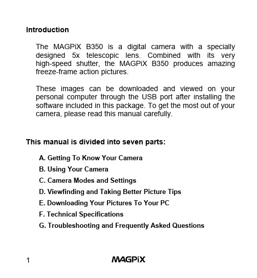
IntroductionThe MAGPiX B350 is a digital camera with a specially designed 5x telescopic lens. Combined with its very high-speed shutter, the MAGPiX B350 produces amazing freeze-frame action pictures.These images can be downloaded and viewed on your personal computer through the USB port after installing the software included in this package. To get the most out of your camera, please read this manual carefully.This manual is divided into seven parts:A. Getting To Know Your CameraB. Using Your CameraC. Camera Modes and SettingsD. Viewfinding and Taking Better Picture TipsE. Downloading Your Pictures To Your PCF. Technical SpecificationsG. Troubleshooting and Frequently Asked QuestionsA. Getting To Know Your CameraBelow are three views of the MAGPiX B350 to help familiarize you with your new camera. The parts and corresponding numbers will be referred to throughout this manual.1 Left Barrel2 Left Objective Lens3 Camera Lens4 Right Objective Lens5 Right Barrel6 Dioptric Knob7 Right Eyepiece8 Shutter/Select Button9 USB Port10 Power/Mode Button11 Left Eyepiece12 Focus Knob13 L CD DisplayFigure 1. Top View8 Shutter/Select Button9 USB Port10 Power/Mode ButtonFigure 2. Front View14 Camera Lens15 Eyepieces16 Battery Compartment17 Tripod MountFigure 3. Side ViewB. Using Your Camera1. Load The Batteries. Open the Battery Compartment (16)and insert two AAA batteries (included), paying attention to insert them in the correct direction. Close the compartment.Always download your picturesregularly (see Part E), if thebatteries run out, your pictures willbe lost. A flashing LCD indicatesthe batteries are low. You shoulddownload your pictures as soon aspossible. Figure 5. Loading The Batteries2. Turn On Your Digital Camera. Press Power/Mode Button(10) to turn on the camera. The preset mode of high resolution(HI) allows 52 VGA images and is indicated by a 3-star symbol on the LCD Display (13).Figure 6. High Resolution Figure 7. Pictures Remaining3. Use The Eyepieces (7 & 11) To Aim Your Camera. Thecamera works best at taking pictures of outdoor objects, 40ft away from you or more. Also, since the camera is point and shoot and independent from the binoculars, you do not need to focus the binoculars to get great in-focus pictures.4. Take Your Picture. Hold your MAGPiX B350 steady andaim at a scene or object 40ft. or greater away from you.Press the Shutter/Selection Button (8) to take the picture.You will hear a beep. The LCD Display (13) will show “- - -“, and when the number of available exposures has decreased by one on the LCD Display (13), you will hear another ‘beep’, and the camera is ready to take another picture. If you hear a quick ‘double beep’ and the counter does not go down, it means that there was not enough light for the camera to takea picture..Figure 8. Shooting Symbol Figure 9. LCD Display AfterFirst Exposure5. Turn off Your Camera. Press the Power/Mode Button (10)once and the LCD Display (13) will show “oFF”. - Then press the Shutter/Select Button (8) to turn off the camera.The camera will also automatically shut off after approximately 1minute of inactivity.Figure 10. Off ModeC. Camera Modes and SettingsDifferent camera modes and settings can be cycled through by pressing the Power/Mode Button (10) after the camera is turned on. *** It is important to wait 1 second before each press of the Power/Mode Button. ***1. Off Mode2. Self-timer3. Erase All Pictures4. Erase Last Picture5. Resolution Selection1. Off ModeWhen the camera is turned on, pressing the Power/Mode Button (10) once, will cause “oFF” to show on the LCD Display (13). Then press the Shutter/ Select Button (8) and the camera will turn off.Figure 11. Off Mode2. Self-Timer ModeWhen the camera is turned on, pressing the Power/Mode Button (10) two times, waiting one second between each press of the button - will put the camera in the Self-Timer Mode. When you see the timer icon, press the Shutter/Select Button (8) to activate the self-timer. The camera will beep for 10 seconds before taking the picture automatically. When LCD Display (13) no longer shows “- - -“, the camera is ready to take another picture.Figure 12. High Resolution + Self-timer Figure 13. Low Resolution + Self-timer3. Erase All PicturesWhen the camera is turned on, pressing the Power/Mode Button (10) three times, waiting one second between each press of the button - will put the camera in Erase All Pictures Mode. When you see the Erase All Pictures icon, press the Shutter/Select Button (8) and the LCD will begin to blink. While the LCD is blinking press the Shutter/Select Button (8) again, and the camera will erase all pictures that have been taken.Figure 14. Erase All Pictures4. Erase Last PictureWhen the camera is turned on, by pressing the Power/Mode Button (10) four times, waiting one second between each press of the button - will put the camera in Erase Last Pictures Mode. When you see the Erase Last Pictures icon, press the Shutter/Select Button (8) to erase the last picture. The number of available pictures on the LCD Display (13) will be increased by one.Figure 15. Erase Last Picture5. Resolution SelectionWhen the camera is turned on, pressing the Power/Mode Button (10) five times, waiting one second between each press of the button - will put the camera in Resolution Selection Mode. When you see the Resolution Icon, press the Shutter/Select Button (8) to change the preset high resolution(52 VGA images of 640 x 480 pixels) to low resolution (209QVGA images of 320 x 240 pixels).Figure 16. Changing Between High Resolution and Low ResolutionIf you change the resolution to low,the LCD Display (13) will show thefollowing when you turn on yourdigital camera again. To changethe resolution back to high - followthe steps above one more time.Figure 17. Low ResolutionD. Viewfinding and Taking Better Picture TipsHow to use the binoculars:1. Hold the MAGPiX B350 in a comfortable viewingposition, and adjust the left and right barrels (1 & 5) apart or together until one single circular field is seen with both of your eyes at the same time.2. To adjust the focus, look into the Left Eyepiece (11)with your left eye (with the right eye closed) to aim at any object 5 meters away, rotate the Focus Knob (12) clockwise or anti-clockwise to get the best focus. Then look into the Right Eyepiece (7) with your right eye (with the left eye closed), and rotate the Dioptric Knob (6) to the left or to the right to get the best focus.3. Now you can look with both eyes into the left and righteyepieces (2 & 4) and bring nearby or far away objects into focus by adjusting the Focus Knob (12).Viewfinding• The function of the binocular is as the viewfinder for the binoculars.• The area seen through the binocular is a circular area, approximately 8 times the magnification of originalimage.• The MAGPiX B350 lens produces a 5 times enlarged image with 4x3 standard shape.Figure 17. View area difference between binocular and camera• You do not need to focus the binoculars for a focused picture. The camera is auto-focus and is independentfrom the binoculars.Area Seen Through Binocular Area of Picture Taken• Depending upon the amount of available light, the shutter speed is fast enough that you can capture terrific action shots.• Try taking a picture of a helicopter in flight. You’ll notice that when you view your picture, you will have stopped the helicopter’s rotor blade in mid-flight.E. Downloading Your Pictures To Your PC1. Install the drivers and photo software. The CD includedin the box contains the MAGPiX B350 driver and bonus software (Photo Express 4.0). The driver must be installed before you connect the MAGPiX B350 to your computer.Ulead PhotoExpress is bonus software, and is not necessary to view your pictures.Insert the installation CD into the CD-ROM drive of your computer. A screen will appear as shown in Figure 18.Figure 18. B350 CD start-up screenClick once on “Install MAGPiX B350 Driver” to start the installation of the driver, and follow the instructions on the screen step by step. After the installation is completed, select “Restart your computer now”. (Go directly to step 2, ifyou do not want to install PhotoExpress on your computer). After your computer restarts, re-insert the MAGPiX B350 CDand click once on “Install Ulead Photo Express 4.0” to install Photo Express. Follow the instructions on the screen step by step. After the installation is completed, exit the installation screen and restart your computer.2. Connect your MAGPiX B350 to your computer. Plug inthe large end of the included USB cable to the USB port ofyour computer, and connect the smaller end of this cable tothe MAGPiX B350. Your computer will find new hardware and update its system. Follow the onscreen instructions, if any.3. Downloading your pictures from the MAGPiX B350.By using the MAGPiX Quick Download Utility:1. Make sure the MAGPiX B350 is connected with the USBcable to your computer.2. Launch the MAGPiX B350 by going to: StartàProgramsà MAGPiX B350à MAGPiX B350. (SeeFigure 19).Figure 19. MAGPiX Quick Download Utility3. Click on the Red/Pink camera icon to download imagesfrom the camera.4. The thumbnail images can be enlarged by clicking onthem with your right mouse button. Select the photosyou want to save and click on the save icon and click“Save”.5. After the pictures are downloaded, you may delete thepictures from your MAGPiX B350 by following thedirections on page 8 of this manual.6. You can now open your saved photos with your favoritephoto applications.By using Ulead PhotoExpress:1. Make sure the MAGPiX B350 is connected with the USBcable to your computer.2. Launch the PhotoExpress 4.0 application.3. Along the left hand side of the application, select thefolder that you like to download your pictures to.4. Click on “Get Photos” and select “Digital Camera” fromthe drop down menu, as shown in Figure 20.5. Make sure “MAGPIX B350 “ is selected along the lefthand side of the application under “Select Data Source”6. Click “Acquire” at the bottom left of the screen todownload your pictures in the camera. See Figure 21.7. After the pictures are acquired, you may delete thepictures from your MAGPiX B350 by following the directions on page 8 of this manual.8. Ulead PhotoExpress 4.0 offers many more functionalitiesas an image-editing program. To learn how to use PhotoExpress 4.0, please insert the CD that came with the B350 and select “Ulead PhotoExpress 4.0 User Manual”, or visit on the Internet.Figure 20. Click “Get Photos” and select “Digital Camera”Figure 21. Click ‘Acquire” at the bottom left of the screenF. Technical Specifications• Sensor Resolution: CMOS, 640x480 pixels• Built-in Memory: 8 MB, SDRAM• Image Storage: VGA (640x480) - 52 imagesQVGA (320x240) - 209 images • Status LCD: 3-digit B/W• White Balance: Auto• Exposure: Auto• Shutter Speed: Auto (1/8000 sec, Max.)• Focal Length: 33 mm (equals to 230 mm of 35 mmcamera)• Aperture: F=4• Self Timer: 10 seconds• Interface: USB• Delete Image: All / last one• Auto Power Off: 45 seconds• Battery: 2 x AAA Alkaline Battery• Dimensions: 115x90x55 mm• Weight: 225 grams (w/o battery)• Operating System: Windows 98SE/ME/2000/XP• Veiwfinder Full functioned 8x21 binocularSystem Requirements• Personal computer with an operating system of either Windows 98, 98SE, ME, 2000 or XP.• A CD-ROM to install the driver and application software. • Minimum Penthium II 200 MHz CPU.• 1 USB port available.• VGA Video card able to support a minimum of 640 x 480 24-bit true color resolution.1024 x 768 24-bit true color resolution is recommended.• At least 48 MB RAM for WIN98/ME, and 64 MB RAM for Windows 2000 and WIN XP.• At least 120 MB of free hard disk space.F. Troubleshooting and Frequently Asked QuestionsQ. The pictures I take seem to be blurred or out of focus.A. Try taking pictures of objects or activities 40ft. or further away. Remember, the B350’s lens is focused from 40ft to infinity.Q. I can’t get the B350 to delete my pictures or change to any other mode but ‘OFF’.A. When you press the mode button, you need to wait 1 second before pressing it again. So, when pressing the mode button 3 times to get to the trash icon, you need to wait one second between each press of the mode button. Then, when you see the trash icon, press the shutter button once and the number of pictures will start to blink. While the LCD is blinking, press the shutter button again and the number of pictures remaining will go back to ‘52’.Q. I downloaded my pictures to the computer, but the B350 LCD still shows the same number of pictures taken that I had before I downloaded them – why haven’t they been deleted?A. The B350 does not automatically delete your pictures off of the camera after you have downloaded them to your computer. To take new pictures, you must delete your old pictures by following the instruction on page 8.Q. How do I learn to use the other functions in Photo Express 4.0?A. You can insert the CD that is included with the B350 and select “Ulead Photo Express 4.0 User Manual” from the menu to read the manual for Photo Express 4.0. You can also visit Ulead’s website at .Q. The pictures I downloaded have some purple artifacts or seemto be distorted or have some black spots and lines on them.A. Try reconnecting the USB cable to the computer and to theB350. Make sure the USB cable to securely inserted into both your computer and the B350.Q. The pictures I took have a strong red tint when they are downloaded.A. The B350 is functioning normally. In very limited computer systems with Windows XP, pictures taken indoors under incandescent lighting may appear red. Pictures taken outdoors or under natural lighting are not affected. This phenomenon does not occur under Windows 98se, Me or 2000. Please visit our web site at for a special Windows XP driver. You do not need a different driver, unless you are experiencing a strong red tint.Q. My batteries are low, but I can’t get to my computer to download my pictures. I don’t want to loose my pictures.A. Turn off the B350 (The LCD should be blank). Then open battery compartment and replace your old batteries with new batteries. The B350 will keep your pictures for approximately 1 minute while you are changing the batteries.Q. None of the buttons seem to work. The LCD displays only “HI” and never shows the number of pictures remaining.A. A system error has occurred. Please take out the batteries for2 minutes and re-insert them. Unfortunately, all pictures taken with the B350 that have not been downloaded to your computer will be lost.Q. I inserted the CD, but no menu appears automatically.A. Go to “My Computer” and right click on your CD drive. Then select “AutoPlay” or “AutoRun”. The menu should now appear. If you do not have an option for “AutoPlay/AutoRun, select ‘open’. Then double click on the ‘Drivers’ folder. Inside the drivers folder, is the driver for the MAGPIX B350. Double click on that file and the driver will install automatically.Q. I changed the resolution from Hi to Lo. How do I change the resolution back from Lo to Hi.A. Follow the same steps you used to change the resolution from Hi to Lo and your camera will be back in Hi resolution mode. Q. Every time I try to take a picture, I hear a double beep and the counter does not go down. Why is my camera not taking a picture?A. If you hear a quick ‘double beep’ and the counter does not go down, it means that there was not enough light for the camera to take a picture. Please try to take a picture when there is more light available. The MAGPIX B350 works best outdoors during daylight.Q. When I try to install Ulead PhotoExpress, it keeps asking me for a serial number – Where do I find it?A. You do not need a serial number to install Ulead PhotoExpress. Just make sure that you fill in the ‘Name‘ box and the ‘Company’ box. Filling in ‘home’ or ‘none’ are good responses if the B350 is not being used for a business. After filling in these two lines you should be able to continue the installation.Q. I’ve taken pictures and installed the driver, but when I try to download my pictures, I get a ‘There is a Connection Error’message or a ‘No Photos in Camera’ message.A. Please make sure that you have pictures in the camera. The LCD should show a number less than ‘52’. If the LCD shows ‘52’, please take a picture and try to download the pictures again before proceeding with these instructions. Also, please make sure the USB cable is tightly connected. You may also get this message if the B350’s driver did not install properly. Please follow the directions below according to the operating system you have on your computer.***(If you are using Windows 98 it is important to distinguish between Windows 98 and Windows 98 Second Edition. Here’s how to tell: Go to your CONTROL PANEL and click on SYSTEM. In the window that opens, you will see either just ‘Windows 98’ or you will see ‘Windows 98 Second Edition’.) ***Windows 98 Second Edition / ME / 2000 / XP1. It is very important that you first restart your computer.2. Connect the B350 to the computer.3. - If you have Windows 98SE or ME, go to the ‘Control Panel’and then double click on ‘System’. Then click on the ‘Device Manager’ tab.- If you have Windows 2000, right-click on the ‘My Computer’ icon located on your desktop, and then select ‘Properties’ from the menu that will appear. Click on the ‘Hardware’ tab andthen click on the 'Device Manager' button.- If you have Windows XP, go to Start à Right-click on ‘My Computer’ and select ‘Properties’ from the dropdown menu.Then click on the 'Hardware' tab and click on the 'DeviceManager' button.4. If you see a yellow ‘?’ next to “Other Devices" and "?! USBDIGITAL STILL CAMERA". --> Right click on "?! USB DIGITAL STILL CAMERA" and select ‘remove’ or ‘uninstall’ from the menu. Confirm the removal. (Otherwise go to step 5).5. If the ‘Imaging Devices’ line is present, double click on it. If yousee ‘Dual mode DSC (2770)’ or ‘SQ (9120)’ right click on it and select ‘remove’ or ‘uninstall’. Confirm the removal orun-installation. (Otherwise go to step 6).6. Close the 'System Properties' Window. Do not restart thecomputer7. Go to your Control Panel and double click on Add/RemovePrograms8. Highlight 'MAGPIX B350' and click Add/Remove (orChange/Remove). Confirm the removal of the program. Do not restart the computer9. Highlight 'Ulead Photoexpress 4.0 My Custom Edition' andclick Add/Remove (or Change/Remove). Confirm the removal of the program. (If you cannot find this program, go to step 10).10. Unplug the camera from the computer. Restart the computer11. Insert the MAGPIX B350 installation CD (DO NOT CONNECTTHE B350 TO THE COMPUTER). Click once on ‘InstallMAGPIX B350 Driver’12. Restart the computer13. Connect the camera into the computer. Wait 45 seconds.Windows should find new hardware. (If Windows does not find new hardware after 45 seconds, try switching the USB cable to another USB port.)14. When Windows has finished installing the new hardware(Dual mode DSC (2770)), please wait 2 minutes and thenrestart the computer.15. Disconnect the B350 from your computer.16. Insert the MAGPIX B350 installation CD and click on ‘InstallUlead Photoexpress 4.0’ and complete the installation. Restart your computer.17. Download your photos as described in the B350 user manualusing either the MAGPIX Quick Download Utility or Ulead PhotoExpress.***Windows 981. Disconnect the B350 from USB port of PC. Restart yourcomputer.2. If you installed Ulead PhotoExpress, go to Start--> Settings -->Control Panel -->Double click on Add/Remove Programs (If you did not install PhotoExpress, go to step 4).3. Highlight Ulead Photoexpress4.O My Custom Edition on thelist and click Add/Remove - and confirm complete removal of Ulead Photoexpress.4. Insert the installation CD in to the CD-ROM drive. Click “Exit”when the installation menu appears. Go to “My Computer” and right-click on your CD drive and click “Open”. Double click on the folder ‘OTHER’ and double-click on the folder‘DIRECTX8.0’. Then double click on ‘SETUP.EXE’ andMicrosoft’s DirectX will install automatically.If you prefer, you may also download and install DirectX 8.0 from Microsoft on the Internet at:/downloads/release.asp?ReleaseID=277415. Restart your computer.6. Insert the B350 installation CD. When the menu appears, go tothe next step.7. Click "Install MAGPiX B350 Driver ", and complete theinstallation. Click "Finish". (If a "Welcome" window displays, select "Repair" and click "Next".)8. When "InstallShield Wizard Complete" displays, select "Yes"and click "Finish" to restart system.9. Connect the B350 with USB port of your PC. Wait 45 seconds.Windows should build a new driver database.10. Go to Start--> Programs -->Magpix B350 --> Magpix B350.When the window opens, click on the red camera icon to download your photos. To save the pictures you've just downloaded, click on the disk icon. To enlarge the pictures,right-click on the picture you wish to enlarge.11. If you are satisfied with this download, you can also downloadthe pictures using Ulead PhotoExpress. Please follow the installation procedures for PhotoExpress on page 15.Q. Where can I find more help or information on my MAGPIXB350?A. 。
PARKER派克MPE系列伺服电动机技术手册

options and reduced complexity.
70.8
Continuous Peak
8
• Eight models covering three
frame sizes of 40, 60 and 80 mm
62.0
• 1.4 to 31.3 in-lbs continuous
MPE080
phone: 800.358.9068 / 707.584.7558 fax: 707.584.8015 email: emn_support@
0 0
1000
2000
3000
4000
0 5000
Speed RPM
MPE Common Specifications
1.2
0.26 2.3
Rated Shaft Output Power 1, 2, 3, 4 Current at Rated Speed 1, 2, 3, 4 Voltage Constant 4. 7 Torque Constant 4, 7 Resistance 4, 9
Pout Ir Ke
Tr
in-lb
6.0
10.6
Rated Shaft Output Power 1, 2, 3, 4 Current at Rated Speed 1, 2, 3, 4 Voltage Constant 4. 7 Torque Constant 4, 7 Resistance 4, 9
Pout Ir Ke
Arms Vrms/krpm Nm/Arms
ohm
Rated Shaft Output Power 1, 2, 3, 4 Current at Rated Speed 1, 2, 3, 4 Voltage Constant 4. 7 Torque Constant 4, 7 Resistance 4, 9
TS-9210H-9218H矩阵手册

用户手册
安全须知
为确保设备可靠使用及人员安全,在安装,使用和维护时,请遵守以下事项:
电源
在设备安装时,应确保电源线中的地线接地良好,请勿使用两芯插头,确保设 备输入电源为 100V--240V50/60HZ 的交流电。
电源线
妥善布线,避免被践踏或重物挤压。
工作环境
请勿将设备放置在过冷或过热的地方,保持工作环境的良好通风。在潮湿结露 环境或长时间不使用时,应关闭设备电源。
EDID 支 持 计 算功能
输入信号支持 VIDEO、VGA、色差、DVI、TS-MI、3G/TS--SDI、双绞线差分信 号,输出为 TS-MI、VGA 格式、双绞线差分信号。卡片式结构,极其容易扩展 或更换。并可扩展中控功能,可扩展网络控制。 输入带有自动均衡,有效减少因为线路传输而导致的确定性抖动( ISI); 输出带有预加重功能,以便长线传输后接收端仍可接收信号;输入支持接收 延迟,有效应对当差分对线不等长时进行时间补偿。 输入 TS-MI 信号支持音频环出功能,输出 TS-MI 信号支持音频分离输出(立 体声)功能,能方便与扩声系统连接。 输入输出板卡带指示灯,输入有信号,输出有接设备并且有信号是,指示灯 长亮。 确保有内容保护的媒体能正常显示,如蓝光 DVD、GAME、BOX 等。 VIDEO 信号输入板,VGA 信号输入板带有音频输入接口,配合输出板音频分离 输出功能,能实现音视频同步切换而无需另外配置音频切换设备。 能实时自动计算任意个输出端显示器的 EDID 信息的交集,合集。 当一路输入信号送给多个不同分辨率的显示设备时,能自动获取当前切换状 态的最佳分辨率,并触发信号源更改分辨率(自动模式)。
②、独特功能
.支持多格式信号(TS-MI/DVI/VIDEO/VGA/YPbPr/TS--SDI)输入,模拟数字信号 共存
Parker Hannifin HD系列产品手册说明书
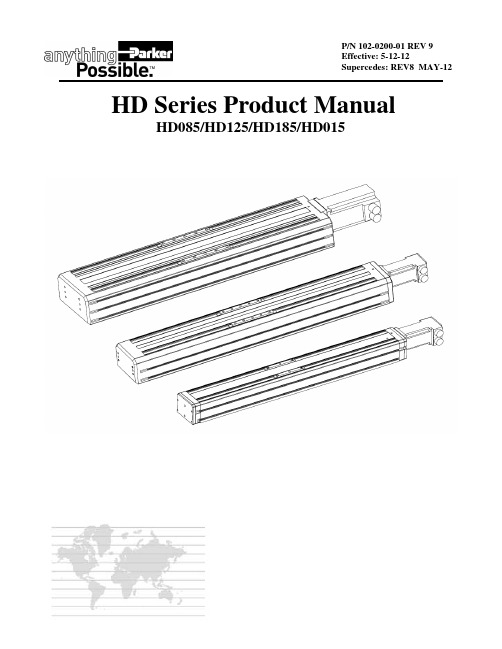
P/N 102-0200-01 REV 9Effective: 5-12-12Supercedes: REV8 MAY-12HD Series Product ManualHD085/HD125/HD185/HD015Important User InformationThe information in the product manual, including any apparatus, methods, techniques, and con-cepts described herein, are the proprietary property of Parker Hannifin Corporation or its licensors, and may not be copied, disclosed, or used for any purpose not expressly authorized by the owner thereof.Since Parker Hannifin Corporation constantly strives to improve all of its products, we reserve the right to change this product manual and equipment mentioned therein at any time without notice.For assistance contact:Parker Hannifin Corporation1140 Sandy Hill RoadIrwin, PA 15642Phone: 724/861-8200800/245-6903Fax: 724/861-3330E-mail:*****************Web site: Table of ContentsREVISION NOTES (5)SECTION 1 - INTRODUCTION (6)PRODUCT DESCRIPTION (6)U NPACKING (6)R ETURN I NFORMATION (7)R EPAIR I NFORMATION (7)W ARNINGS AND P RECAUTIONS (7)S PECIFICATION C ONDITIONS AND C ONVERSIONS (7)SECTION 2 - HD SERIES TABLE SPECIFICATIONS (8)O RDER N UMBER N OMENCLATURE .......................................................................................................................................................... 8-11D IMENSIONAL D RAWINGS ..................................................................................................................................................................... 12-21E XPLODED VIEW/PARTS LIST ................................................................................................................................................................. 22-29G ENERAL T ABLE S PECIFICATIONS……………………………………………………………………………………………………...30-31BALLSCREW/TABLE MAXIMUM SPEEDS (32)BEARING /LOADING ENGINEERING REFERENCE .................................................................................................................... 33-36 REFLECTED INERTIAS ENGINEERING REFERENCE ................................................................................................................. 37-39 CARRIAGE STIFFENESS/BASE-RAIL MOMENT OF INERTIAS (40)SECTION 3 - COMPONENT SPECIFICATIONS/ MOUNTING (41)B RAKES ................................................................................................................................................................................................. 41-43L IMIT & H OME S ENSORS (44)C OUPLINGS (45)SECTION 4 - BASE MOUNTING PROCEDURES (46)M OUNTING S URFACE R EQUIREMENTS (46)B ASE M OUNTING M ETHODS (46)SECTION 5– WRAP AROUND INFORMATION (47)HD085 WRAP AROUND (47)HD125 WRAP AROUND (48)HD185 WRAP AROUND (49)SECTION 6 - MAINTENANCE AND LUBRICATION..................................................................................................................... -50-52B ELT S EALS INFORMATION.................................................................................................................................................................... 50-51S QUARE R AIL B EARING L UBRICATION (52)G ROUND B ALLSCREW L UBRICATION (52)SECTION 7 - MOTOR/TABLE PERFORMANCE CHARTS/TECHNICAL INFORMATION .................................................... 53-59 HD085 MOTOR/TABLE PERFORMANCE CHARTS . (53)HD125 MOTOR/TABLE PERFORMANCE CHARTS (54)HD185 MOTOR/TABLE PERFORMANCE CHARTS (55)H V232 MOTOR TECHNICAL INFORMATION (56)S M232/233 MOTOR TECHNICAL INFORMATION (57)C MP/MPP921 MOTOR TECHNICAL INFORMATION ................................................................................................................................... 58-59Revision Notes :REV-2 (3-28-06) :UPDATED CATALOG CONFIGURABLE OPTIONSUPDATED EXPLODED BOMS HD125/HD185HD125 ITEM# 9A/9B CARRIAGE WEAR BARSHD185 ITEM#9 CARRIAGE WEAR BARITM#18/28 QTY NOW 2(NEW BUMPER ASSEMBLY)NEW BRAKE ASSEMBLYS 002-2601/002-2611 PG 34/35REV-3 (10-08-07) :UPDATED IXX VALUES ON PAGE 30 FOR HD085 HD125 AND HD185UPDATED DIMS IN RED ON PAGES 12,13REV-4 (3-31-08) :CORRECTED TYPO ON PAGE 45 . MAINTENANCE FREE OPERATION UP TO 5 YEARS/2540KM OF LIFEREV-5 (8-01-08) :ADDITIONAL PAGES FOR THE INDUSTRIAL GRADE OPTION AND NEW WRAP ASSEMBLIESREV-6 (1-19-09) :PAGE 16 CORRECTED THE MOTOR OPTION F122-HD125 DIM “A” NOW 25.0 WAS 20.0 DIM B” WAS 28.0 NOW 33.0 PAGE 19 CORRECTED THE MOTOR OPTION F122-HD185 DIM “A” NOW 25.0 WAS 20.0 DIM “B” WAS 8.0 NOW 13.0 REV-7 (5-26-10) :PAGE 30 CORRECTED 1200MM TRAVEL HD185 MAX BREAKAWAY TORQUE NOW 0.38 WAS 0.25 N-MPAGE 31 CORRECTED 1200MM TRAVEL HD185 MAX BREAKAWAY TORQUE NOW 0.38 WAS 0.25 N-MREV-8 (4-25-12) :PAGE 31 CORRECTED 1200MM TRAVEL HD185 MAX BREAKAWAY TORQUE NOW 0.38 WAS 0.25 N-M(SAME AS REV 7 BUT ONLY PAGE 30 WAS UPDATED)REV-9 (5-12-12) :PAGE 52 Changed Alvania grease to GADUS S2 V100 2 (just a name change)Chapter 1 - IntroductionProduct DescriptionHD series linear table line is a robust industrial positioner that is easy to apply, easy to install, and easy to maintain. The robust design begins with and extruded body and carriage that provide exceptional beam strength and carriage stiffness. The linear bearings and ballscrew are precision components selected for their long life at 100% duty operation, they both em-ploy lube seals which provide maintenance free operation in most applications. The HD series also includes IP30 rated belt seals that protect the interior components from debris.The HD series is very easy to apply. As part of the configurable number, users can select options such as screw lead, motors, brakes and limit/homes. With motors as part of standard table, system level performance is provided in the form of graphs to enable quick application without the need for a complex motor sizing exercise.HD series has three distinct sizes allowing for ease of applying to application.HD085 85mm wide x 70mm tallHD125 125mm wide x 85mm tallHD185 185mm wide x 95mm tallThe above sizes make the HD series ideal for applying to applications requiring Cartesian set-ups.HD series also offers a standard extruded idler/square rail HD015 60mm wide x 62mm tall for use in gantry style applica-tionsUnpackingUnpackingCarefully remove the positioner from the shipping crate and inspect the unit for any evidence of shipping damage. Report any damage imme-diately to your local authorized distributor. Please save the shipping crate for damage inspection or future transportation. Incorrect handling of the positioner may adversely affect the performance of the unit in its application. Please observe the following guide-lines for handling and mounting of your new positioner.DO NOT allow the positioner to drop onto the mounting surface. Dropping the positioner can generate impact loads that may result in flat spots on bearing surfaces or misalignment of drive components.DO NOT drill holes into the positioner. Drilling holes into the positioner can generate particles and machining forces that may effect the op-eration of the positioner. Parker Hannifin Corporation will drill holes if necessary; contact your local authorized distributor.DO NOT subject the unit to impact loads such as hammering, riveting, etc. Impacts loads generated by hammering or riveting may result in flat spots on bearing surfaces or misalignment of drive components.DO NOT push in belt seals when removing positioner from shipping crate. Damaging belt seals may create additional friction during travel and may jeopardize the ability of the beltseals to protect the interior of the positioner. If belt seals are pushed in run carriage by hand over entire travel and the belts will reset.DO NOT submerge the positioner in liquids.DO NOT disassemble positioner. Unauthorized adjustments may alter the positioner’s specifications and void the product warranty.Return InformationReturnsAll returns must reference a “R eturn M aterial A uthorization”, (RMA), number. Please call your local authorized distributor or Parker Hannifin Corporation Customer Service Department at 800-245-6903 to obtain a “RMA” number.Repair InformationOut-of-Warranty RepairOur Customer Service Department repairs Out-of-Warranty products. All returns must reference a “RMA” number. Please call your local authorized distributor or Parker Hannifin Corporation Customer Service Department at 800-245-6903 to obtain a “RMA” number. You will benotified of any cost prior to making the repair.Warnings and PrecautionsVertical OperationDepending upon your load and ballscrew selection the carriage and load may ‘backdrive’ in power loss situations potentially causing product damage or personal injury. An electro-mechanical brake, which will activate in response to a loss of power (option ‘B2’), can be used to pre-vent potential product damage or personal injury. Note: Actual maximum load for brake holding is dependent on screw lead.Strain Relieve Electrical ComponentsAll electrical components (such as brakes, encoders, and limit/home switches) must be strain relieved. Failure to strain relieve electrical wires or cables may result in component failure and/or possible personal injury.Specification Conditions and ConversionsSpecifications are Temperature DependentCatalog Specifications are obtained and measured at 20 Degrees C. Specifications at any other temperature may deviate from catalog specifications. Minimum to Maximum continuous operating temperature range (with NO guarantee of any specification except motion) of a standard unit before failure is 5 - 70 Degrees C. Certain components can be eliminated or substituted to improve operation at these tempera-tures. Positioners with low temperature or high temperature components will be handled as specials, contact your local distributor.Specifications are Mounting Surface DependentCatalog Specifications are obtained and measured when the positioner is fully supported, bolted down (to eliminate any extrusion deviation), and is mounted to a work surface that has a maximum flatness error of 0.013mm/300mm (0.0005”/ft).Specifications are Point of Measurement DependentCatalog Specifications and Specifications in this manual are measured in the center of the carriage, 37.5mm above the carriage surface. All measurements taken at any other location may deviate from these values.IndustrialNSEE PAGES #13,14 FOR ADDITIONAL MOTOR MOUNTS OFFERINGSIndustrial NSEE PAGES #16,17 FOR ADDITIONAL MOTOR MOUNTS OFFERINGSIndustrialNSEE PAGES #19,20 FOR ADDITIONAL MOTOR MOUNTS OFFERINGSHD SERIES PRODUCT MANUAL 11PARKER HANNIFIN CORPORATIONELECTROMECHANICAL AUTOMATION DIVISIONSECTION 2HD015 CONFIGURABLEHD085 DIMENSIONAL DRAWINGS Please refer to for the latest, updated drawingsON PG 12STANDARD BELT TENSION SET @ 75NHD125 DIMENSIONAL DRAWINGS Please refer to for the latest, updated drawingsON PG 15 STANDARD BELT TENSION SET @ 120NHD185 DIMENSIONAL DRAWINGS Please refer to for the latest, updated drawings25.0BRAKE OPTIONQTY. 4 TAPPED HOLESM6 x 1.0 x 12.0dp.ENDVIEWON PG 18 STANDARD BELT TENSION SET @ 120NHD015 DIMENSIONAL DRAWINGS Please refer to BILL OF MATERIALSHD085 EXPLODED VIEWBILL OF MATERIALSBILL OF MATERIALSHD185 EXPLODED VIEWHD015 BILL OF MATERIALSHD015 EXPLODED VIEWGeneral Table Specifications Standard grade: note : see page #31 for Industrial grade STANDARD GRADESTANDARD GRADEGeneral Table Specifications Industrial grade: note : see page #30 for Standard gradeBALLSCREW INFORMATION *Note:When employing 20mm diameter 40mm lead ballscrewmaximum rps=56Maximum Carriage Linear Speed (mm/s)Maximum Screw Speed (Revs/Sec)HD Series Engineering ReferenceThe following performance information is provided as a supplement to the product specifications pages. The following graphsand formulas are used to establish the table life relative to the applied loads. The useful life of a linear table at full catalog specifications is dependent on the forces acting upon it. These forces include both static components resulting from payload weight, and dynamic components due to acceleration/deceleration of the load. in multi-axes applications, the primary posi-tioner at the bottom of the stack usually establishes the load limits for the combined axes. When determining life/load, it iscritical to include the weight of all positioning elements that contribute to the load supported by the primary axis.Table Life Load Chart : Compression (Normal Load)This graph provides a “rough cut” evaluation of the support bearing life/load characteristics. The curves show the life/load relationship when the applied load is centered on the carriage, normal (perpendicular) to the carriage mounting surface. For final evaluation of life vs. load,Table Life Load Chart : Thrust(Axial load)These charts are to be used in conjunction with the corresponding formulas found under Product Informa-tion at to establish the life / load for each bearing (4 per table)HD185 105HD SERIESHD12577.0 Kgf ( TENSION) 65 mm70 mm57.5 mm107.5 mm(PAGE 28)-77.0Kgf ( COMPRESSION)125.0 Kgf -75 Kgf77.0 Kgf ( TENSION)125.0 Kgf SIDE LOAD163.5 Kgf(1603N) PAGE 27100 KgfLife @1603N =4500kmREFLECTED INERTIASPLEASE NOTE : ONE MUST ADD THE ADDITIONAL EFFECTS OF CUSTSOMER LOADREFLECTED INERTIAS CONTINUED:REFLECTED INERTIAS CONTINUED:CARRIAGE STIFFNESS:BASE/RAIL ASSEMBLY MONMENTS OF INERTIAS:EXTERNAL BRAKE INFORMATION : NOTE : OFFERED ON HD125/HD185 SERIES ONLYHD085 OFFERS ON MOTORNOTE :ANALYSIS OF REQUIRED BRAKING TORQUE SHOULD BE DONE.THE REQUIRED BRAKING TORQUE SHOULD BE MULTIPLIED BY A SERVICE FACTOR OF 1.5 TO 4.0 DEPENDING ON THE APPLICATIONCONSULT FACTORY FOR MORE DETAILED INFORMATIONHD125 BRAKE ASSY (002-2611-02) MOUNTING INSTRUCTIONSHD185 BRAKE ASSY (002-2601-02) MOUNTING INSTRUCTIONSLIMIT HOME SENSORSMOUNTING:INSERT INTO UPPER MOST T-SLOT AND POSITION WHERE REQUIRED. TIGHTEN SCREW TO FIX. POSITION.NOTE : MAGNET TRIPPER CENTERED INTERNALLY ON CARRIAGE (BOTH SIDES)COUPLINGS:Mounting Surface RequirementsProper mounting of the HD SERIES is essential to optimize product performance.All specifications are based on the following conditions:The positioner must be bolted down along its entire length.The positioner must be mounted to a flat, stable surface with a flatness error less than or equal 0.020mm/300mm.Catalog Specifications may deviate for positioners mounted to surfaces that do not meet the above conditions.If the surface does not meet these specifications the surface can be shimmed to comply with these requirements.If mounting conditions require that the table base is overhung, table specifications will not be met over that portion of the table. Additionally, in X-Y Systems the overhung portion of the Y-axis may not meet specifications due to the additional error caused by deflection and non-support of the base. Contact Parker Hannifin Corporation for guidelines on specifications ofoverhang applicationsBase Mounting MethodsThe HD series can mounted via two ways:1. Tapped holes in the base.Reference the dimensional drawings on pages 11-142. Toe ClampingHD085 WRAP AROUNDBELT TENSIONING:LOOSEN ITEM #15 ALLOWING MTR ADP TO SLIDE FREELY.USE ITEM #13 TO TIGHTEN/LOOSEN TENSION.MEASURE BELT TENSION WITH BELT TENSION METER.(FOR MORE INFORMATION CONTACT FACTORY)BELT TENSION SHOULD MEASURE 75N-95NHD125 WRAP AROUNDBELT TENSIONING:LOOSEN ITEM #17 ALLOWING ITEM 8 TO SLIDE FREELY. USE ITEM #20 TO TIGHTEN/LOOSEN TENSION.MEASURE BELT TENSION WITH BELT TENSION METER. (FOR MORE INFORMATION CONTACT FACTORY)BELT TENSION SHOULD MEASURE 110N-130NHD185 WRAP AROUNDBELT TENSIONING:LOOSEN ITEM #17 ALLOWING ITEM 8 TO SLIDE FREELY. USE ITEM #20 TO TIGHTEN/LOOSEN TENSION.MEASURE BELT TENSION WITH BELT TENSION METER.(FOR MORE INFORMATION CONTACT FACTORY)BELT TENSION SHOULD MEASURE 110N-130NBelt Seal Information :Qty 2 belt seals per table (except HD015)。
无需网络中控就能实现IPAD对高清混合矩阵的网络控制
无需网络中控就能实现IPAD对高清混合矩阵的网络控制ATER在不断探索产品新功能的同时,也非常注重提升产品的用户使用体验。
“触手可及,所见即所得”是对使用产品的终极要求。
特别是计算机、网络技术和控制理论的迅速交叉发展以来,他的影响已经深入到行业的各个方面。
为了使用户快捷、方便对数字高清混合矩阵进行网络自由控制,ATER成功将网络控制功能集成到AGP-P系列高清混合矩阵内部,用户可以跳过独立的网络中控,直接利用IPAD控制高清混合矩阵。
众所周知,不同的用户有不同需求,对仅使用了高清混合矩阵、但又寻求智能便捷的控制方式的用户来说,面板按键控制、红外控制、RS232控制、软件控制,已完全不能满足他们的需要,他们追求一种更加有趣、更加个性的使用体验方式。
ATER将产品内嵌了网络控制界面,将网络控制功能集成到AGP-P系列高清混合矩阵,真正给予产品智能化的定义。
内嵌的控制程序,不需要安装,用户直接通过登录局域网IP地址,即可与ipad 、Android、WPhone、XP、win7、win8等智能平台相连,实现多席位对设备进行管理和设置。
这样,用户就无须为了实现更加智能的控制方式、而去购买能够控制多个设备的独立网络中控,就像不用为了买一朵花而被迫买下整个花园。
同时,在系统安装布线时无需再处理网络中控与高清混合矩阵之间的线路,减少了工程布线的繁琐,也提高了整个系统的便捷度。
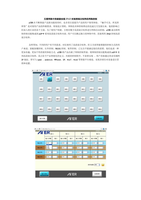
利用IPAD直接控制AGP-P系列高清混合矩阵的过程方便快捷,只需通过以下几个步骤即可实现:1、用无线路由器搭建一个局域网,把IPAD与ATER派克系列混合矩阵放在一个局域网中;2、在IPAD上打开浏览器,输入网址:192.168.0.3进入矩阵场景调用界面,点击相应场景号按钮即可进行场景调用;3、如果您需要切换端口,只需要点击页面里的“端口切换”按钮,即进入端口切换界面,通过下拉菜单选择输入卡及输入卡端口号即可进行信号切换;4、如果您想保存场景,只需在“端口切换”界面,点击右下角的“保存场景”,并通过下拉菜单选择场景号,点击场景保存就可。
DFK 33GP1300 技术手册说明书
技术细节1.要件速览 42.尺寸图 6 2.1DFK 33GP1300 带脚架适配器的C型接口 (6)2.2DFK 33GP1300 不带脚架适配器的C型接口 (7)2.3DFK 33GP1300 带脚架适配器的CS型接口 (8)2.4DFK 33GP1300 不带脚架适配器的CS型接口 (9)3.I/O 连接器 10 3.16-pin I/O 连接器 (10)3.1.1TRIGGER_IN (10)3.1.2STROBE_OUT (11)4.光谱特征 12 4.1红外截止滤波器 (12)4.2光谱灵敏度 - P1300 (12)5.相机控制 13 5.1传感器读出控制 (13)5.1.1像素格式 (13)8-Bit Bayer Raw (13)5.1.1.15.1.1.212-Bit Packed Bayer Raw (14)16-Bit Bayer Raw (14)5.1.1.35.1.1.4YUV 4:2:2 (14)5.1.1.5YUV 4:1:1 (14)5.1.2分辨率 (14)5.1.3读出模式 (15)5.1.4帧速率 (15)5.1.5局部扫描偏移 (17)5.2图像传感器控制 (18)5.2.1曝光时间 (18)5.2.2增益 (18)5.3自动曝光及增益控制 (18)5.3.1自动曝光 (19)5.3.2自动增益 (19)自动参考值 (19)5.3.35.3.4强光缩减 (19)5.3.5自动曝光限制 (20)5.3.6自动增益限制 (20)5.4触发 (21)5.4.1触发模式 (21)5.4.2触发极性 (21)5.4.3软件触发 (22)5.4.4触发脉冲计数 (22)5.4.5触发源 (22)5.4.6触发重叠 (23)5.5触发定时参数 (23)5.5.1触发延迟 (23)5.5.2触发去抖时间 (23)5.5.3触发遮罩时间 (24)5.5.4触发噪声抑制时间 (24)5.6数字I/O (24)5.6.1通用输入 (24)5.6.2通用输出 (25)5.7频闪 (25)5.7.1频闪启用 (25)5.7.2频闪极性 (26)5.7.3频闪操作 (26)5.8白平衡 (26)5.8.1自动白平衡 (26)5.8.2白平衡模式 (27)手动白平衡 (28)5.8.35.9图像处理 (29)5.9.1伽玛 (29)5.9.2查找表 (29)5.10色彩处理 (30)5.10.1色调 (31)5.10.2饱和 (31)5.10.3色彩校正矩阵 (31)5.11自动功能感兴趣的区域 (33)5.11.1自动功能ROI启用 (33)自动功能ROI预设 (34)5.11.25.11.3自动功能ROI自定义矩形 (34)5.12用户设置 (35)5.12.1用户设置选择器 (35)5.12.2加载用户设置 (35)5.12.3保存用户设置 (36)默认用户配置 (36)5.12.46.Rev i s i o n H i story 371要件速览2尺寸图2.1DFK 33GP1300 带脚架适配器的C型接口2.4DFK 33GP1300 不带脚架适配器的CS型接口3I/O 连接器3.16-pin I/O 连接器相机后视图1开极闸M OS F E T最大限制0.2A(ID)!2启动电流最低条件3.5mA!3 G:地O:输出I:输入3.1.1TR IGG ER_I NTRIGGER_IN线可用于将曝光时间的开始与外部事件同步。
派克汉尼汾中国传动控制产品及解决方案说明书

冶金行业提供传动控制元件、系统及解决方案聚焦钢铁行业对外开放及国外直接投资以来,最早成立的三家外国合资企业之一。
在中国拥有2000多条产品线,产品涵盖50多个市场,为企业提供航空航天,环境控制,机电,过滤,流体与气体处理,液压,气动,过程控制,密封与屏蔽九大技术解决方案和服务。
产品应用及解决方案主要涉及重型商用车、风力发电、船舶制造、海洋勘探、钢铁、工程机械、高速铁路和工厂自动化等。
派克汉尼汾中国总部设在上海,在中国设有15个生产基地及9个销售办事处,在华已经拥有3000多名员工。
聚焦钢铁行业派克提供切实有效的元件及系统解决方案,并与钢铁制造商建立了广泛的合作关系。
致力为钢铁行业提供完善的传动控制产品解决方案,我们不断评估行业需要,开发新产品,以符合钢铁行业当前及未来的需求。
行业先行者作为一家为钢铁制造商提供元件与系统解决方案的卓越供应商,我们的产品系列具有足够的宽度和深度,可为钢铁行业提供适合多种应用场合的产品。
我们的工程师可协助您选择并评估所需产品,以符合您特定的钢铁制造需要,凭借优质产品,准时交货和综合技术支持,值得您的信赖。
工程专长派克提供非常完善的技术协助与支持,在设计阶段,我们的销售及应用工程师与您共同努力,挖掘产品价值。
我们不仅希望您使用我们的元件和系统,更希望帮助您有效地使用这些产品。
产品专业性许多供应商在谈到自己的产品时都非常专业,但是在这方面派克做得更好。
我们提供液压、气动、流体连接件、过滤和密封等多种产品。
专业的产品使您更省时省钱,这是您选择派克的又一个理由。
0102/china液压产品在1780mm 热轧机液压系统的应用可为客户提供液压动力站,超大蓄能器组,以及定制液压油缸。
鉴于这些动力系统的工作压力变化比较大,所采用的液压泵均为PV-plus, 能有效提高系统工作的稳定性,大大降低轧机再咬钢时系统压力的冲击,同时减少生产线的故障率,降低液压系统维护保养时间。
液压元件在棒材轧线液压系统的应用基于棒材轧线连续性作业的特性,派克提供液压系统的设计、配置及采用的高品质元件,具备操作稳定、易于控制、高效及故障率低等特点,同时解决了客户对系统污染的忧虑,提供在线油液污染检测设备,进行全天候监控并自动预警,及时提醒操作人员进行保养和维护工作,减少系统故障。
2022年度四川省中小企业发展专项资金

专项后补助
15
108
高强度耐磨硬质合金圆锯片的研究及产业化
成都壹佰科技有限公司
专项后补助
15
109
叠块式组合磁芯产品及生产工艺研发
四川东阁科技有限公司
专项后补助
15
110
超纯铬铁及钒系氮化合金新材料研发
荥经华盛冶金科技有限公司
专项后补助
15
111
高耐磨SE皇冠钻的研发及产业化应用
专项后补助
15
116
抗雷击、耐环境的光纤复合架空地线
德阳汇川科技有限公司
专项后补助
15
117
环保型轻质建筑陶粒制备工艺研究与应用
四川亨利德新型建筑材料有限公司
专项后补助
15
118
缓释型抗菌磷酸盐玻璃的制备及阻垢性能研究与应用
成都天佑晶创科技有限公司
专项后补助
15
119
冷光片关键技术研究及其在军用车导光板中的应用
四川泰虹科技有限公司
专项后补助
40
82
基于能源物联网技术的健康监测型智能开关设备的研发
四川电器集团中低压智能配电有限公司
专项后补助
15
83
WD系列高性能离心泵的设计研发
成都永益泵业股份有限公司
专项后补助
15
84
用于第三代半导体材料制备的高功率大面积微波等离子体CVD设备的研发
成都纽曼和瑞微波技术有限公司
成都市易迪森新能源技术有限公司
专项后补助
15
50
管家婆章鱼侠NGP项目
成都章鱼侠科技股份有限公司
专项后补助
100
51
基于云计算技术的“企企云”新一代公有云ERPSaaS平台
parker型号总汇

PARKER 400XR Serie 802-2193C Linear Actuator - Precision Slide - 7 Inches Travel
PARKER COMPUMOTOR MICROSTEPPING INDEXER DRIVER SX6-DRIVE
PARKER RR2AU14A *USED*
PARKER COMPUMOTOR CM232BE-00924
PARKER 8Z-V8AR-SS *. IN BOX*
CTC PARKER AUTOMATION 05-03023-103 S3-71113-106 ISA QTY
6012 PARKER UV DRAWER ULTRAVIOLET UV CURE DRAWER 110 VOLT
Parker 71-006880-02 Stepper Motor
PARKER FM2DDDKN 55 FLOW CONTROL VALVE 5000PSI MAX
Parker Servo Electric Cylinder ETB32-B08PA20-?FM100-A
PARKER PRR SERIES PRECISION RIGHT ANGLE GEAR REDUCER
Eurotherm Drive 620 Vector Link Series 620L SDD Parker
6012 PARKER UV DRAWER ULTRAVIOLET UV CURE DRAWER FOR PARTS 110 VOLT
D6430D6438D6436D6432高清矩阵信号切换系统说明书V1.1

用户手册广州市迪士普音响科技有限公司http://警告为了防止对使用者、其他人造成危害、设备损坏或财产损失,请务必遵守下列基本注意事项:本标志表示的是「禁止」的内容本标志表示的是「必须」的内容目录一、包装说明 (1)二、高清矩阵系统说明 (1)2.1 高清矩阵功能的概述 (1)2.2 数字高清矩阵的分类 (1)三、安装连接 (8)3.1 矩阵主机与机柜的安装 (8)3.2 RS-232通信接口的连接方法 (9)3.3 VGA接口的连接方法 (10)3.4 RCA接口的连接方法 (10)3.5 数字高清DVI矩阵后面板示意图及接线说明 (11)3.6 数字高清HDMI矩阵后面板示意图及接线说明 (12)四、操作说明 (13)4.1 面板按键控制方式 (13)4.2 RS-232协议控制指令系统 (13)4.3 应用软件使用说明 (15)4.3.1 《SWITCHER 2.0》软件介绍 (15)4.3.2 软件的启动 (15)4.3.3 软件功能说明 (15)4.3.4 Auto自动循环切换功能 (16)4.3.5 Keyboard 切换功能 (17)4.3.6 Custom Code 手动输入指令 (18)4.3.7 Code Group 用户指令集 (19)4.3.8 Send/receive Code List收发指令列表 (20)五、系统应用实物连接实例 (20)5.1 数字高清DVI矩阵(以HD D6442为例) (20)5.2 数字高清HDMI矩阵系统连接图(以D6451为例) (21)一、包装说明二、高清矩阵系统说明2.1 高清矩阵功能的概述高清矩阵切换器是可以把多个高清信号源与多个高清信号输出端同时连接起来。
它可以很容易地将多路高清信号在多个兼容高清信号的显示器或者投影机上自由切换或者分配,是专门为高清信号的切换而设计的高性能智能矩阵开关设备。
高清矩阵系统主要应用于广播电视工程、多媒体会议厅、大屏幕显示工程、电视教学、指挥控制中心等场合。
VAISALA DM70 说明书

操作手册维萨拉公司DRYCAP®DM70 型手持式露点仪M010091ZH-E出版人Vaisala Oyj 电话(国际长途):(+358 9) 894 91邮政信箱26 传真:(+358 9) 8949 2227FIN-00421 HelsinkiFinland欢迎访问我公司网站:/(英文)/ (中文)© Vaisala 2007未经版权持有人的事先书面许可,不得以任何形式或任何手段,无论是电子的还是机械的(其中包括影印),对本手册任何部分进行复制,也不得将其内容传达给第三方。
内容如有变更,恕不另行通知。
注意:本手册并未构成维萨拉对客户或者最终用户承担的任何具备法律约束力的义务。
所有具备法律约束力的承诺与协议,均包含于适用的供货合同或者《销售条款》。
本中文手册仅供参考,如有不符,以英文手册为准。
第1章____________________________________________________________________目录第1章概述 (7)安全 (7)安全事项总体说明 (7)信息反馈 (8)环保 (8)商标 (8)质保 (9)第2章产品概述 (11)维萨拉DRYCAP® DM70型手持式露点仪简介 (11)基本功能与选件 (12)部件说明 (13)第3章使用准备工作 (15)装卸电池组 (15)电池组充电 (16)按钮与菜单切换 (17)设备通电 (17)第4章露点测量 (19)测量 (20)第5章用户界面 (21)主画面 (21)菜单 (22)显示菜单 (23)参数和单位 (23)舍入 (25)保持/保存 (25)维萨拉___________________________________________________________________1操作手册___________________________________________________________________图形历史 (26)功能菜单 (27)报警 (27)模拟输出 (29)模拟输出的选择与定标 (29)自校准 (30)自动自校准 (31)关闭自动自校准 (31)手动自校准 (31)传感器净化 (33)打开/关闭传感器自动净化 (33)更改传感器自动净化时间间隔 (34)传感器手动净化 (34)变送器校准(仅限于DMP248) (36)记录/查看菜单 (36)记录数据 (36)停止记录 (38)查看已记录数据 (38)存储器状态 (39)清空数据存储器 (39)记录数据转储至PC (40)环境菜单 (40)压力设置 (40)设置菜单 (41)用户界面 (41)语言 (42)自动断电 (43)程序快捷键 (43)按键音与背光 (44)日期和时间 (45)测量设置 (46)自动自校准 (46)自动净化 (46)分子量 (46)净化时间间隔 (46)设备信息 (47)出厂设置 (48)第6章固定式变送器的现场校准检查 (49)2_____________________________________________________________M010091ZH-E第1章____________________________________________________________________DMT340/DMT242/DMT142的现场标定检查 (49)DMP248的现场校准检查 (51)第7章工艺采样 (53)采样器 (54)DSC74 (54)DSC74B (55)DSC74C (56)DMT242SC (58)DMT242SC2 (58)采用DSC74采样器连接带压工艺装置 (59)DSS70A采样系统 (61)DSS70A的采样步骤 (63)DSS70A的维护 (64)电池充电 (64)更换电池 (65)更换过滤器 (67)更换熔断器 (68)第8章SF6气体绝缘设备内部的湿度测量 (69)概述 (69)工作环境 (70)测量 (70)第9章校准、调整与维护 (73)校准 (73)用户校准与调整 (73)调整DM70 (73)以DM70作为基准或者终端,调整DMT340系列变送器 (74)露点调整 (75)两点式相对湿度调整 (75)使用DM70对DMT340系列变送器进行两点式相对湿度调整 (77)露点T d/f的调整 (79)DM70的T d/f调整 (79)维萨拉___________________________________________________________________3操作手册___________________________________________________________________使用DM70对DMT340系列变送器进行T d/f调整80与T d/f I/II相同 (81)单点调整 (82)温度调整 (83)DM70的温度调整 (83)单点调整 (84)两点调整 (84)使用DM70对DMT340系列变送器进行温度调整85与T I/II相同 (86)单点调整 (86)两点调整 (87)维萨拉服务中心 (88)第10章报废、拆解与弃置 (89)第11章技术规格 (91)被测量的变量 (91)露点温度 (91)温度 (93)PPM(ppm v或ppm w) (94)绝对湿度(建议使用DMP74A型探头) (94)混合比(建议使用DMP74A型探头) (94)相对湿度(DMP74A) (95)测量环境 (95)探头一般规格 (95)MI70型显示表头 (96)显示表头一般规格 (96)电池组 (97)DMP74型探头+ MI70型显示表头= 维萨拉DRYCAP® DM70型手持式露点仪 (98)一般规格 (98)电磁兼容性 (98)采样器 (98)DMT242SC型采样器 (98)DMT242SC2型采样器,带Swagelok管接头98DSC74型带压气体采样器 (99)DSC74B型双压采样器 (99)DSC74C (99)4_____________________________________________________________M010091ZH-E第1章____________________________________________________________________DMCOIL (99)DSS70A型采样系统 (100)配件 (101)尺寸 (102)插图目录图1DM70型手持式露点仪 (13)图2安装电池组 (15)图3按钮 (17)图4主画面 (21)图5菜单 (23)图6参数和单位菜单 (25)图7报警 (27)图8模拟输出 (29)图9自校准屏幕 (33)图10传感器净化屏幕 (35)图11变送器校准屏幕 (36)图12记录 (36)图13Environment(环境)菜单 (41)图14用户界面 (42)图15保持/保存更换为自校准 (44)图16测量设置菜单 (46)图17设备信息 (47)图18显示表头与探头信息 (47)图19变送器校准消息 (52)图20DSC74采样器,带转换接头 (54)图21DSC74B (55)图22DSC74C缺省组装方式 (56)图23DSC74C其它组装方式(用于狭窄空间) (57)图24DMT242SC与DMT242SC2采样器 (58)图25DM70及仪表箱 (62)图26抬起系统 (65)图27采样系统倒放 (66)图28更换过滤器 (68)图29集气选项 (70)图30通气量调整螺钉的拆卸 (71)图31DMP74A精度 (92)图32DMP74B精度 (92)图33DMP74C精度 (93)图34尺寸,单位:毫米(英寸) (102)维萨拉___________________________________________________________________5操作手册___________________________________________________________________ 表格目录表1测量时间间隔和最长记录时间 (37)表2配件列表 (101)6_____________________________________________________________M010091ZH-E第1章________________________________________________________________概述第1章概述安全安全事项总体说明本手册采用以下方式对重要安全说明予以强调:警告“警告”表示存在严重危险,用户要提高警惕。
Avenview HDMI H.264 IP视频壁画解码器 编码器与矩阵模式支持产品说明说明书
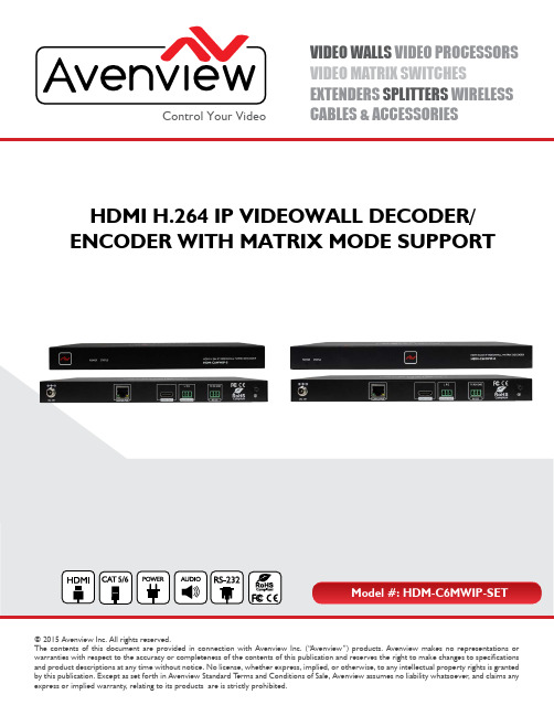
VIDEO WALLS VIDEO PROCESSORS VIDEO MATRIX SWITCHES EXTENDERS SPLITTERS WIRELESS CABLES & ACCESSORIES Control Your Video © 2015 Avenview Inc. All rights reserved.The contents of this document are provided in connection with Avenview Inc. (“Avenview”) products. Avenview makes no representations or warranties with respect to the accuracy or completeness of the contents of this publication and reserves the right to make changes to specifications and product descriptions at any time without notice. No license, whether express, implied, or otherwise, to any intellectual property rights is grantedHDMI H.264 IP VIDEOWALL DECODER/ENCODER WITH MATRIX MODE SUPPORTProduct Application & Market Sectors Corporate House Of WorshipMilitary ResidentialEducation IndustrialTABLE OF CONTENTS1.GETTING STARTED (1)1.1 IMPORTANT S AFE G UARDS (1)................................................................................................................11.2 SAFETY I NSTRUCTIONS1.3 REGULATORY NOTICES FEDERAL COMMUNICATIONS COMMISIION (FCC) (2)2.INTROD U CTION (3).....................................................................................................................4 2.1 P AC K AGE CONTENTS2.2 BE F ORE INSTA LL ATION (4)2.3 A PPLI CATION DIAGRAM (5)2.4 P ANE L DESCRI P TION (6)2.4.1 FRONT PANEL (SENDER/ENCODER, HDM-C6MWIP-S ) (6)2.4.2 REAR PANEL (SENDER/ENCODER, HDM-C6M W IP-S) (6)3.INSTALLATION (HDM-C6M W IP-SET) (8)3.1 APPLICATION (8)3.1.1 IP MATRIX SWITCH GUIDE (8)3.2 SINGLE SWITCH NETWORKING GUIDE (9)4.PC CONFIGURATOR (11)5.SPECIFICATIONS .............................. (15)6.TROUBLESHOOTING (17)2.4.3 FRO N T PANEL (RECEIVER/DECODER, HDM-C6M W IP-R) (7)2.4.4 FRONT PANEL (RECEIVER/DECODER, HDM-C6M W IP-R) (7)3.3 NETWORKING GUIDE (10)SECTION 1: GETTING STARTED1.1Please read all of these instructions carefully before you use the device. Save this manual for future reference.What the warranty does not cover•Any product, on which the serial number has been defaced, modified or removed.•Damage, deterioration or malfunction resulting from:•Accident, misuse, neglect, fire, water, lightning, or other acts of nature, unauthorized product modification, or failure to follow instructions supplied with the product.•Repair or attempted repair by anyone not authorized by us.•Any damage of the product due to shipment.•Removal or installation of the product.•External causes to the product, such as electric power fluctuation or failure.•u se of supplies or parts not meeting our specifications.•Normal wear and tear.•Any other causes which does not relate to a product defect.•Removal, installation, and set-up service charges.1.2The Avenview HDM-C6M W IP-SET, HDMI H.264 IP Matrix Decoder/Encoder has been tested for conformance to safety regulations and requirements, and has been certified for international use. However, like all electronic equipments, the HDM-C6M W IP-SET should be used with care. Read the following safety instructions to protect yourself from possible injury and tominimize the risk of damage to the unit.Do not dismantle the housing or modify the module.Dismantling the housing or modifying the module may result in electrical shock or burn.Refer all servicing to qualified service personnel.Do not attempt to service this product yourself as opening or removing housing may expose you to dangerous voltageor other hazardskeep the module away from liquids.Spillage into the housing may result in fire, electrical shock, or equipment damage. If an object or liquid falls or spills onto the housing, unplug the module immediately.Have the module checked by a qualified service engineer before using it again.Do not use liquid or aerosol cleaners to clean this unit. Always unplug the power to the device before cleaning.This equipment has been tested and found to comply with part 15 of the F CC rules. These limits are designed to provide reasonable protection against harmful interference in a residential installation.Any changes or modifications made to this equipment may void the user’s authority to operate this equipment.ONlY USE THE PROVIDED POWER CABLE OR POWERADAPTER SUPPLIED. DO NOT TAMPER WITH THEELECTRICAl PARTS. THIS MAY RESULT IN El ECTRICALSHOCK OR BURN.DO NOT TAMPER WITH THE UNIT. DOING SO WIllVOID THE WARRANTY AND CONTINUED USE OFTHE PRODUCTTHE VIDEO BOARDS ARE VERY SENSITIVE TO STATIC.PLEASE ENSURE IF RACK MOUNTED OR INSTALLED ONA SURFACE, IT SHOULD BE IN A GROUNDEDENVIROMENT.The Avenview HDM-C6MWIP-SET, HDMI H.264 IP Videowall/Matrix Decoder/Encoder delivers end-to-end streaming media over IP networks. The HDM-C6MWIP-SET is composed of two units a Decoder and an Encoder. The Decoder H.264/MPEG-4 AVC video compression format, it receives the encoded IP signal through LAN port and decodes video/audio signal out through HDMI interface, it also supports stereo de-embeding and streaming resolutions up to 1920 x 1200@60Hz.Point to Point - (Direct Connection with CAT5/6) - 330ftPoint to Multi - point with CAT5/6 requires a POE Network Switch which supports port based, IGMP v2.0 or above protocol. For large application, we would recommend Cisco SG family and the Cisco Catalyst.Videowall and Matrix Function – with CAT 5/6 cable without any signal loss add multiple Sources to multiple encoders which links via LAN by cascading any POE Gigabit Ethernet switches up to 3 levels, to the decoder connected to the HD Monitors at different locations on the Network. Transporting full HD 1080p video and internally H.264 video compressionadapts to available network bandwidth if needed while retaining vivid picture with PCM audio.FEATURES:- Flexible PC,WEB GUI iPad control;- CEC Function on the RX;- Supports live IP video stream decoding 480p@60Hz to 1920 x 1200@60;- Supports POE;- Allows video previewing via iPad App and Windows 7 software 352x288@5Hz;- Supports multiple interfaces HDMI, DVI signals over IP networks;- Supports audio embedding and de-embedding;- Built in-auto scaler;- Supports H.264 features baseline profile, main profile and high profile;- Supports H.264, TCP/IP, Telnet, UDP and IGMP;- Support Telnet, WEB GUI control and 3rd Party control sytems API commands;- Supports Auto IP, Zero-configuration networking (zeroconf)- Seamless switching, no black screen, no frame lock.- Configurable encoding bit rate up to 30 Mbps - Auto input format detection - HDCP compliantOther features include:Before you start the installation of the HDMI Extender, please check the package contents.2.2BEFORE INSTALLATION•P ut the product in a level and stable location. If the product falls, it may cause damage or malfunction to components within the casing.•Do not place the product in temperatures under 0˚C or over 50˚C. High humidity may also cause the unit to malfunction.•U se the DC power adapter with correct specifications supplied with the unit. If the improper power supply is used, this may result in malfunction of the unit and may cause fire.•Do not twist or pull by force the ends of the UTP cable. It will cause malfunction.2.32.4 2.4.1 FRONT PANEL (Sender/Encoder, HDM-C6MWIP-S)1.Power LED: Indicates if the unit is powered OFF or ON by a RED LED2.Status LED: Steady Blue Light ON indicates unit is communicating properly. LED blinking waiting on Source 2.4.2 REAR PANEL (Sender/Encoder, HDM-C6MWIP-S)3.HDMI IN: Connect to HDMI/DVI Source.4.5.Stereo Audio OUT: Connects to an audio outputdevice such as an amplifier for audio de-embedding.6.CAT5/6: Used for transporting video/audio streams to Decoder RX units connected.7.RS 232: RS-232 Data pass-through port for receiving /sending commands to RS 232 devices.8.Power Jack: DC 12V 1AGround Screw: Ground connection prevent devicefrom voltage damage.2.4.3 FRONT PANEL (Receiver/Decoder, HDM-C6MWIP-R)1.Power LED: Indicates if the unit is powered OFF or ON by a RED LED.2.Status LED: Steady Blue Light ON indicates unit is communicating properly. LED blinking waiting on Encoder.2.4.4 FRONT PANEL (Receiver/Decoder, HDM-C6MWIP-R)3.Ground Screw: Ground connection prevent devicefrom voltage damage.4.Power: 12V 1A DC Power Jack.ed for accepting video/audio streams from theEncoder TX units connected.6.HDMI OUT: Connect to HDMI Display.7.Stereo Audio OUT: Connects to an audio outputdevice such as an amplifier for audio de-embedding.8.RS 232 : RS-232 Data pass-through port for receiving/sending commands to RS 232 devices.3. To setup Avenview HDM-C6M W IP-SET please follow these steps for connecting to a device:1.Turn off all devices including monitors / TV.2.3.4.5.6.7.Connect an HDMI source (such as a Blu-Ray Disc player or P C) to the Encoder HDM-C6MW IP-S.Connect CAT5/6 from Encoder to Decoder at the CAT5/6 port.Connect an HDMI out from HDM-C6MW IP-R decoder to a Display/Monitor .Connect Audio out to Speakers or Amplifier.Ensure all cable connections are secure and not loose.P lug in 12V DC power (supplied) and connect the HDM-C6MW IP-S and HDM-C6MW IP-R to power jack respectively. P ower on HDMI Source.P ower on the HDMI display.3.13.1.1 IP Matrix Switch Guide8.9.NOTE:For network setup please see the Network switch configuration guide and Network Connection guide to acheive best results.3.2The illustration above is an example of how the user can connect using a 24 port network switch.The following brands are recommended and was tested resulting in stable working conditions.1.Cisco brand24-port 100Mbps Ethernet switch: WS-C2960-24TC-L24-port 1000Mbps Ethernet switch: SG300-2824-port 1000Mbps PoE Ethernet switch: SG300-28P, WS-C2960S-24PS-L, WS-C2960X-24PSQ-L2.HUAWEI Brand24-port 100Mbps Ethernet switch: S2700-26TP-EI-AC24-port 1000Mbps PoE Ethernet switch: S5700-28P-PWR-LI-AC3.3Avenview M-Series HDMI over IP units can be networked together with a recommended Layer 2 Gigabit Smart Switches. As mentioned previously in section 3 the importance of calculation for the capacity of the switch meets the requirements of the number of encoders/decoders you have on your network. These units can perform well over a standard network infrastructure, however the quality of this infrastructure is critical. We have tested many brands of switches all of which perform well in small system configurations of around 10 Encoders and Decoders. However, for larger installations, Avenview highly recommends using CISCO SG300/500 or CATALYST series switches.3.3.1 Simple Setup Guide for Network switchM-series should be connected to a Layer 2 managed switch which supports Multicast & IGMP snooping.Do not connect any units to the switch until all the network switch configuration has been. For recommended switches and PDF configuration guides please see the ‘downloads’ section of any M-series device at .3.3.2POE Re q uirementsIt is not necessary to change the IP addresses of the encoders and decoders units – factory default AutoIP is used to configure correct IP addresses to simply work out of the box.DHCP addresses are not recommended, while Static addresses are for supervised setups and network strict enviroments.Failure to note the IP settings of a ny unit changed may result in a complicated reset procedure.Most M-Series installations use the POE (Power Over Ethernet) function to power the encoder & decoders units.HDM-C6MXIP & HDM-C6MWIP devices are Class 0 rated POE devices, they can require up to 15.4W of power each, but tested their actual power draw is between 5-7W. In order to calculate the number of devices that is recommeneded on a network switch please divide the total POE power capa city of the switch by 15.4.Please see the example:CISCO SG300-52P with a POE power output of 375W: 375 / 15.4 = 24.35.From the answer 24 devices can be powered by this switch. In order to have all ports powered by POE on a network switch, please see the example:SG300-52MP which provides 740W. 740 / 15.4 = 48. From the answer 48 devices can be powered by this switch.3.3.3Data BandwidthEach HDM-C6MXIP-S encoder will produce up to 50Mb/s of data > therefore 10 x encoders will require 10 x 50Mb/s = 0.5 Gbps.4.4.1 Setting a Static IP on Your ComputerBefore using the Avenview PC Configurator, please ensure you download the most recent version from the product HDM-C6M W IP-S Sender and HDM-C6M W IP-R Receiver website link /downloads PC control software .All devices must be are in the same network segment. To verify and properly control the devices, please set a static IP on your computer. See the instructions below if not sure on how to proceed:The Sender and Receiver units are pre-configured with AutoIP. Upon connecting the units to a stand alone network switch (without router attached), the units will be on IP address range at 169.254.1.1 and subnet mask 255.255.0.0. Set your computer's IP address as 169.254.X.X and subnet mask as 255.255.0.0. A Windows 7 PC/Laptop is used as an example to configure a static IP address.1.Click Start .2.Choose Control Panel > Network and Internet > Network and Sharing Center > Change Adapter Settings , right click Local Area Connection , and then choose Properties.You can connect multiple HDM-C6M W IP-S and the HDM-C6MW IP-R H.264 decoder to build a modular IP matrix. With the PC configurator, you can configure and manage this function. For more information, see the user guide of PC configurator.Minimum System Requirements PC SoftwareOperating System: Microsoft® Windows® XP, Windows® Vista, Windows® 7 or Windows® 8 CPU: 1.5 GHzMemory: 1 GB of RAMHDD: 32 GB of available hard disk space Network: 10/100 NIC3.Double-click Internet Protocol Version 4 (TCP/IPv4).4.Select Use the following IP address. After configuring the settings in the following example,click OK.IP addres s: 169.254.2.5Subnet mask: 255.255.0.05.Click OK.Configuring Your Operating SystemFirewallYour operating system firewall may block some features of PC Configurator and prevent it from communicating with Sender and Receiver. A computer running Windows 7 is used as an example to configure your operating system firewall through either of the following two approaches.Method 1You can configure the firewall in the Windows Firewall panel on your computer, for example select both Home/Work (Private) and Public for PC Configurator & Matrix.Method 2You can also configure the firewall in the Windows Security Alert window. When starting MaintainTool, the Windows Security Alert may display. If so, use the administrator privileges to select a network you allow this software to communicate on, for example select both private and public networks, and then click Allow access.5.Input Video Signal 0.5~1.2 V p-pEncoding Data Rate Output Video Ports Output Video TypeOutput Video ResolutionsUp to 30 Mbps, configurable Video Impedence 100 Ω100 ΩInput DDC Signal 5 V p-p (TTL)End-to-End Time LatencyAbout 60ms-90ms (Low latency mode) About 250ms-300ms (High quality mode)Input Audio Format StereoOutput Audio Ports 1 x Phoenix connector Control Method Rear panel CAT5/6 port , PC configurator and RS-232EnvironmentalOPERATING TEMPERATURE 32˚ ~ 104˚F (0˚ to 40˚C)STORAGE TEMPERATURE -4˚ ~ 140˚F (-20˚ ~ 60˚C)RELATIVE HUMIDITY20~90% RH (no condensation)1400 x 1050@60Hz 1680 x1050@60Hz ,1920 x1080@60Hz, 1920 x 1200@60Hz YPbPr:1 x CAT5/6H.264/MPEG-4 AVCLarge IP stream:480p@60Hz~1920 x 1200@60Hz Small IP stream: 352x288@5HzPower Supply12 V 1 A DC Power Consumption6W (Max.) Shipping Dimensions (L X H X D) 12.2'' x 3.0'' x 7.1''Product Dimensions (L X H X D)9.3'' x 1.0'' x 3.7"Weight 1 lbsESD Protection Human body model: -±8kV (air-gap discharge)-±4kV (contact discharge)Output Audio Format StereoAbout 60ms-90ms (Low latency mode) About 250ms-300ms (High quality mode)Audio embedded in streaming media input1 x Phoenix connectorStereoPC configurator and RS-23212 V 1 A DC 6W (Max.) Human body model: -±8kV (air-gap discharge)-±4kV (contact discharge)32˚ ~ 104˚F (0˚ to 40˚C)-4˚ ~ 140˚F (-20˚ ~ 60˚C)20~90% RH (no condensation)12.2'' x 3.0'' x 7.1''10.5'' x 1.0'' x 4.4''HDMI :480p@60Hz,576p@50Hz ,800 x 600@60Hz,1024 x768@60Hz , 720p@50Hz, 720p@60Hz , 1280 x 800@60Hz,1280x1024@60Hz ,1366 x 768@60Hz,1440x900@60Hz,1600 x 1200@60Hz,1680 x 1050@60Hz ,1080p@24Hz,1080p@25Hz ,1080p@30Hz,1080p@50Hz, 1080p@60Hz, 1920 x 1200@60HzNA1 x HDMI HDMI 1.31.3 lbsNA NA 720 x 480i@60Hz,720 x 480p@60Hz , 720 x 576i@50Hz,720 x 576P@50Hz , 1280 x720p@50Hz,1280x720p@60Hz 1920 x1080i@50Hz,1920 x 1080i@60Hz CVBS:480i@60Hz,576i@50Hz6. 2.Check the IP address and subnet mask of your computer.The computer, Sender , Receiver and switch should be in the same network segment. Therefore, set your computer's IP address as 169.254.X.X and subnet mask as 255.255.0.0.For more information, see the description in the networking guide.1.Check all devices are powered on.2.Check all cables are securely seated and connected properly.3.Check the LED STATUS indicators on the Receiver s to see if Senders and Receiver s are linked correctly. Blue Steady=OK Blue Blinking=standby To link the devices us e the PC configurator on your PC/Laptop, drag the TX to the RX and click apply.4.Check that source device is powered on and the HDMI cable is connected.PC Configurator (HDMI over IP)Maintain Tool3.Check the switch configur ation, an d that IGMP snooping and all the other functions are enabled.Check the displays are powered on and the correct input selection.Check the LED STATUS indicators on the Receivers to see if Senders and Receivers are linked correctly. Blue Steady=OK Blue Blinking=standby To link the devices use the PC configurator on your PC/Laptop, drag the TX to the RX and click apply.4.Check the A/V device is playing a video with sound .5.Check the A/V devices audio output with an RCA jack to a speaker oramplifier, also use a headphones if the equipment has a 3.5mm audio out.6.Check the A/V devices are not set to mute or 0 for volume.5.6.Check native EDID timings from the manufactures guide to match theReceiver output resolution . If so, replace the displays with other models.7.E xample switch to HDMI 1 if a display's HDMI 1 port is connected to Receiver via an HDMI cable.8.Ensure the displays /monitor support HDCP.Check all the devices are powered on..Check all cables are securely seated and connected properly.Check that Sender supports the resolutions of the input signals. Formore information about the resolutions, see "Specifications" of"Introduction" section.Check the switch configuration, and that IGMP snoopingand all the other functions are enabled.9.7.Check Receiver is not set to mute , open PC configurator and right click on the Receiver and on the drop down select mute . For more information, see the user guide of PC configurator.1.2.3.No audio 1.No Live preview on Windows7 or iPad AppPlease ensure your HDM-C6M W IP-S, CTRLPRO-MIP and your wirless router is on the same network segment.2.For Windows 7/iPad app, please ensure the below units are at the following versions:HDM-C6MXIP-S V2.8.3HDM-C6MXIP-R V2.8.2CTRLPRO-MIP V 1.5/5.1.0(v5.1.1)Software Versions:WINDOWS-M V2.5.10CTRLPRO-M PC V7.0.01.All HDMI over CATx transmission distances are measured using Belden CAT6A (625MHz),4-Pair,UTP-Unshielded, Riser-CMR, Premise Horizontal Cable, 23 AWG Solid Bare CopperConductors, Polyolefin Insulation, Patented Double-H spline, Ripcord, PVC Jacket usingQuantum 980 signal HDMI Video Generator Module with Video Pattern T esting and shieldedends.2.The transmission length is largely affected by the type of category cables, also the type of HDMIsources, and the type of HDMI display. The testing result shows solid UTP cables (usually in theform of 300m or 1000ft bulk cable) can transmit a lot longer signals than stranded UTP cables(usually in the form of patch cords). Shielded STP connectors are better suit than unshieldedUTP connectors. A solid UTP CAT6A cable shows longer transmission length than solid UTPCAT5E/6E cable.3.EIA/TIA-568-B termination (T568B) for category cables is recommended.4.T o reduce the interference among the unshielded twisted pairs of wires in category cable, youcan use shielded STP cables with shielded connector to improve EMI problems, which occurs inpoor wiring environments with unplanned cable runs situated away from EMI interference.5. Because the quality of the category cables has the major effects in how long transmission distancewill be made and how good is the received signal on the display, the actual transmission lengthis subject to high quality category cables. For resolution greater than 1080i or 1280x1024, asolid CAT6E 250MHz cable is the only viable choice.PERFORMANCE GUIDE FOR HDMI OVER CATEGORY CABLE TRANSMISSIONPERFORMANCE RATING TYPE OF CATEGORY CABLEWIRING SHIELDING CAT5CAT5E CAT6SOLID u NSHIEl DED (u Tp)✶✶✶✶✶✶✶✶✶✶✶SHIEl DED (STp)✶✶✶✶✶✶✶✶✶✶✶✶STRANDED u NSHIEl DED (u Tp)✶✶✶✶✶SHIEl DED (STp)✶✶✶✶TERMINATION PLEASE USE EIA/TIA-568-B TERMINATION (T568B) AT ANY TIMEAvenview Warranty CertificateA VENVIEW CORP. (“Avenview”)warrants Avenview-branded product(s) contained in the original packaging against defects in materials and workmanship when usednormally in accordance with Avenview's enclosed manual guidelines for a period of THREE (3) YEARS from the date of original retail purchase - Warranty Period. Avenview’spublished guidelines include but are not limited to information contained in technical specifications, user manuals and service communications.LABOR: During the Warranty Period of THREE (3) YEARS, Avenview will repair or replace the product(s) at no cost using new or used parts equivalent to novel performanceand reliability if the product(s) is determined to have abide by Avenview’s published guidelines. Cost of Labor applicable to product(s) after Warranty Period. For labor costs, please contact ********************.PARTS: During the Warranty Period of of THREE (3) YEARS, Avenview will supply new or rebuilt replacements in exchange for defective parts of the product(s) at no cost ifthe product(s) is determined to have abide by Avenview’s published guidelines. Cost of Parts applicable to product(s) after Warranty Period. For part(s) costs, please contact ********************.To obtain Warranty: (a) proof of purchase in the form of a bill of sale or receipted invoice reflecting that the registered product(s) is within warranty period must be presented to obtain warranty service; (b) product(s) must be registered at time of purchase. Failure to do so will result in applicable parts and labor charges. Returning product(s) mustbe shipped in Avenview’s original packaging or in packaging pertaining equal degree of protection to Avenview’s. Both Avenview and purchaser are responsible for freight charges and brokerages when shipping the product(s) to the receiver.NOT COVERED BY THIS WARRANTYThis warranty does not apply to any non-Avenview branded product(s); non-registered Avenview product(s). This warranty does not apply: (a) to cosmetic damage, includingbut not limited to scratches, dents and broken cords; (b) to damage caused by use with another product; (c) to damage caused by accident, abuse, misuse, liquid contact, fire, earthquake or other external cause; (d) to damage caused by operating the Avenview product(s) outside Avenview’s manuals or guidelines; (e) to damage caused by service performed by anyone who is not a representative of Avenview or an Avenview authorized personnel; (f) to defects caused by normal wear and tear or otherwise due to thenormal aging of the Avenview product(s), or (g) if any serial number has been removed or defaced from the Avenview product(s).AVENVIEW IS NOT LIABLE FOR DIRECT, SPECIAL, INCIDENTAL OR CONSEQUENTIAL DAMAGES RESULTING FROM ANY BREACH OF WARRANTY OR CONDITION, OR UNDER ANY OTHER LEGAL THEORY, INCLUDING BUT NOT LIMITED TO LOSS OF USE; LOSS OF REVENUE; LOSS OF ACTUAL OR ANTICIPATED PROFITS (INCLUDING LOSS OF PROFITS ON CONTRACTS); LOSS OF THE USE OF MONEY; LOSS OF ANTICIPATED SAVINGS; LOSS OF BUSINESS; LOSS OF OPPORTUNITY; LOSS OF GOODWILL; LOSS OF REPUTATION; LOSS OF, DAMAGE TO, COMPROMISE OR CORRUPTION OF DATA; OR ANY INDIRECT OR CONSEQUENTIAL LOSS OR DAMAGE REPAIR OR REPLACEMENT AS PROVIDED UNDER THIS WARRANTY IS THE EXCLUSIVE REMEDY OF THE CONSUMER. Some states do not allow the inclusion or limitation of incidental or consequential damages, or allow limitations on duration implements of the Warranty Period; therefore the above limitations or exclusions may not be applicable to you. This warranty gives you specific legal rights, and you may have other rights which vary from state to state.1100 Military Rd., Kenmore, NY 142171.866.508.0269TECHNICAl SuppORTDisclaimer While every precaution has been taken in the preparation of this document, Avenview Inc. assumes no liability with respect to the operation or use of Avenview hardware, software or other products and documentation described herein, for any act or omission of Avenview concerning such products or this documentation, for any interruption of service, loss or interruption of business, loss of anticipatory profits, or for punitive, incidental or consequential damages in connection with the furnishing, performance, or use of the Avenview hardware, software, or other products and documentation provided herein.AV Connectivity, Distribution And Beyond...。
Parker Hannifin ERV系列杠杆式扩展式电动驱动器说明说明书

E R V Se r i e s ContentsOverview....................................................................................................54Specifications............................................................................................55T echnical.Data .ERV5.Loading.....................................................................................56.ERV8.Loading.....................................................................................57.Deflection............................................................................................58.Effective.Belt.Pull................................................................................58Dimensions................................................................................................59Options .Carriage.Length..................................................................................60.Spliced.Units (60).Bumpers.rmation.................................................................................64Application.Fax.Form (66)ERV Series Rodless ActuatorsParker.Hannifin.CorporationActuator.DivisionWadsworth,A Phone:.1-866-P ARK-ACTemail:*************************website:/actuatorE R V S e r i e s54Actuator Division1-866-PARK-ACTThe ERV SeriesExpanding.on.the.ER,.the.ERV.was.designed.with.an.external.carriage.containing.outboard.roller.bearing.support.for.higher.loads...The.actuator.is.designed.to.directly.interface.with.our.structural.framing,.providing.a.simple.and.cost.effective.solution.for.single.or.multiple-axis.systems.The ERV design means . . . .•..High.loading.to.3590.N •..High.speeds.to.5m/sec •..High.thrust..to.808.N•..Multi-axis.connectivity.for..Gantry.systems•..Strokes.to.6.meters.for.single..extrusion,.spliced.units.for..longer.strokes.•..Internal.belt.drive.•..Extrusion.body.cylinder.with..additional.center.web.for.rigidity..and.axial.stiffness.The ERV multiple design options can be matched to your application demands.•..2.profile.sizes.(56.and.80mm)•..Polyurethane.steel.reinforced.drive.belt•..Standard.and.extended.carriages.for.high.loads•..Ready.to.mount.stepper.or.brushless.servo.motors.ERV Markets and ApplicationsWith.thousands.of.axes.installed.worldwide,.the.ERV.series.rodless.actuator.has.proven.to.be.a.robust.and.reli-able.solution.for.numerous.motion.control.applications.across.many.markets.and.industries...Listed.below.are.some.examples.of.where.and.how.the.ERV.series.rodless.actuator.has.been.successfully.applied........Markets and Industries ServedApplication Examples55Actuator Division1-866-PARK-ACTE R V S e r i es1...P arallel.driven.unit.efficiency.=.inline.efficiency.x.0.92...R epeatability.is.unidirectional.achieved.under.ideal.conditions.and.slow.speeds...Actual.repeatability.may.vary.with.the.application.3...L oad.Capacities.shown.are.based.on.1.billion.inches.of.expected.travel.life.@.1.m/s.4...T raction.Force.is.speed.dependent...The.values.shown.are.based.on.0.5.m/s.speed.Operating Temperature Range0°.to.60°C.(32°.to.140°F)ERV Specifications56Actuator Division1-866-PARK-ACTStatic Moment Loads .Determine.which.moment.loads.are.induced.by.the.static.load...Locate.the.center.of.gravity.of.the.load.and.the.length.of.the.moment.arm...Moment Arm Lengths .Determine.the.moment.arm.lengths.associated.with.each.moment.load.by.measur-ing.the.distance.from.the.center.of.the.load.to.the.center.of.the.carriage.in.each.moment.load.direction.Pitch Moment .When.determining.the.pitch.moment.arm,.it.is.necessary.to.consider.the.distance.from.the.top.of.the.load.attachment.plate.to.the.center.of.the.carriage.bearings...For.the.ERV5.Series,.this.distance.is.40mm.F zyERV5 LoadingStandard CarriageExtended CarriageGraph Legend1600 (360)L O A D ,N (l b )LOADING (F z ) vs.LIFE1400 (315)1200 (270)1000 (225)800 (180)600 (135)400 (90)200 (45)05001000150020002500LIFE (Millions of Inches)800 (180)L O A D ,N (l b )SIDE LOADING (F y ) vs.LIFE700 (158)600 (135)500 (113)400 (90)300 (68)200 (45)100 (23)LIFE (Millions of Inches)80 (59)M O M E NT ,N m (l b -f t )ROLL MOMENT (M x ) vs.LIFE70 (52)60 (44)50 (37)40 (30)30 (22)20 (15)10 (7)0500LIFE (Millions of Inches)80 (59)M O M E N T ,N m (l b -f t )PITCH MOMENT (M y ) vs.LIFE70 (52)60 (44)50 (37)40 (30)30 (22)20 (15)10 (7)LIFE (Millions of Inches)M O M E N T ,N m (l b -f t )YAW MOMENT (M z ) vs.LIFE60 (44)50 (37)0LIFE (Millions of Inches)80 (59)M O M E N T ,N m (l b -f t )ROLL MOMENT (M x ) vs.LIFE60 (44)40 (30)20 (15)0LIFE (Millions of Inches)100 (74)120 (89)140 (103)M O M E N T ,N m (l b -f t )PITCH MOMENT (M ) vs.LIFE250 (184)200 (148)150 (111)100 (74)50 (37)500LIFE (Millions of Inches)M O M E N T ,N m (l b -f t )YAW MOMENT (M ) vs.LIFE150 (111)50 (37)100 (74)020002500LIFE (Millions of Inches)1m/s2m/s3m/s4m/s5m/s57Actuator Division1-866-PARK-ACTE R V S e r i e sERV8 LoadingStatic Moment Loads .Determine.which.moment.loads.are.induced.by.the.static.load...Locate.the.center.of.gravity.of.the.load.and.the.length.of.the.moment.arm...Moment Arm Lengths .Determine.the.moment.arm.lengths.associated.with.each.moment.load.by.measur-ing.the.distance.from.the.center.of.the.load.to.the.center.of.the.carriage.in.each.moment.load.direction.Pitch Moment .When.determining.the.pitch.moment.arm,.it.is.necessary.to.consider.the.distance.from.the.top.of.the.load.attachment.plate.to.the.center.of.the.carriage.bearings...For.the.ERV8.Series,.this.distance.is.47mm.F zyStandard CarriageExtended Carriage3000 (675)L O A D ,N (l b )LOADING (F z ) vs.LIFE2500 (563)2000 (450)1500 (338)1000 (225)500 (113)50020002500LIFE (Millions of Inches)L O A D ,N (l b )SIDE LOADING (F ) vs.LIFE1400 (315)1200 (270)1000 (225)800 (180)600 (135)400 (90)200 (45)050020002500LIFE (Millions of Inches)160 (118)MO M E N T ,N m (l b -f t )ROLL MOMENT (M x ) vs.LIFE140 (103)120 (89)100 (74)80 (59)60 (44)40 (30)20 (15)0LIFE (Millions of Inches)180 (133)M O M E N T ,N m (l b -f t )PITCH MOMENT (M y ) vs.LIFE500LIFE (Millions of Inches)M O M E N T ,N m (l b -f t )YAW MOMENT (M z ) vs.LIFELIFE (Millions of Inches)M O M E N T ,N m (l b -f t )ROLL MOMENT (M ) vs.LIFE500LIFE (Millions of Inches)500 (369)M O M E N T ,N m (l b -f t )PITCH MOMENT (M y ) vs.LIFE400 (295)200 (148)100 (74)1000LIFE (Millions of Inches)300 (221)600 (443)M O M E N T ,N m (l b -f t )YAW MOMENT (M ) vs.LIFE500LIFE (Millions of Inches)Graph Legend1m/s2m/s3m/s4m/s5m/s58Actuator Division1-866-PARK-ACTDeflectionFERV5ERV8ERV5ERV8Effective Belt PullD E F L E C T I O N (m m )4.03.02.52.01.00.500800160024003200UNSUPPORTED LENGTH (mm)40001.53.5D E F L E C T I O N (m m )DEFLECTION AT VARIOUS LOADS4.03.02.52.01.00.500800160024003200UNSUPPORTED LENGTH (mm)40001.53.5M a x E f f e c t i v e P u l l ,N (l b )Effective Belt Pull vs.Speed700 (158)800 (180)500 (113)300 (68)100 (23)Speed (m/s)900 (203)12345600 (135)400 (90)200 (45)Effective Belt Pull vs.SpeedM a x E f f e c t i v e P u l l ,N (l b )600 (135)500 (113)400 (90)200 (45)100 (23)Speed (m/s)700 (158)59Actuator Division1-866-PARK-ACTE R V S e r i e sCarriage Mounting DetailERV5 Standard CarriageERV8 Standard Carriage ERV8 Extended CarriageERV5 Extended Carriage60Actuator Division1-866-PARK-ACTCarriage Style (S, L)Standard carriageExtended carriageSpliced UnitsStandard.units.are.available.in.lengths.up.to.20.feet...For.additional.length,.spliced.units.are.available.Carriage Features•.Bearing.Wheels.-.12.wheels.for.standard.carriage .-..24.wheels.for.extended.carriage •.Eccentric.Pre-loaded.wheels •.Concentric.Wheel•.2.options.for.carriage.loading,.-..Positive.(Toward.Actuator).-..Negative.(Away.from.Actuator).•.Magnet.for.Limit.and.Home.Switches.(Shown.with.Wipers)Bumpers (B)Optional.bumpers.are.designed.to.prevent.over-travel.and.can.be.adjusted.along.the.full.length.of.travel...The.bumpers.are.fixed.to.the.actuator.extrusion.via.a.standard.T -slot.(M8.SHCS.and.T-nut).61Actuator Division1-866-PARK-ACTE R V S e r i esFelt Wiper (W)Although.not.100%.sealed,.the.felt.wiper.option.is.designed.to.wipe.contaminants.away.from.entering.the.carriage.assembly.Carriage with Wiper Carriage without Wiper62Actuator Division1-866-PARK-ACTMachined GussetsMachined.gussets.provide.a.high.strength,led.perpendicular.Material:...6063-T6.Aluminum...alloy,.clear.anodized Machining:.NoneDrop-In T-Nuts20-2828M Dimensions20-4080M Dimensions20-4040M Dimensions20-2856M Dimensions4 x 6.8(.27)THRU12.5(.49)53(2.09)27(1.06)14(.55)14(.55)27(1.06)5(.20)28(1.10)2 x 8.3THRU(.33)17.5(.69)35(1.38)6(.24)38(1.50)20(.79)20(.79)38(1.50)2 x 6.8THRU(.27)12.5(.49)25(.98)27(1.06)14(.55)14(.55)27(1.06)5(.20)Toe ClampFor.attachment.of.ERV8.profiles.to.each.other,ed.in.pairs...Requires.M6.socket.head.cap.screws.Part Number 500-000900Dimensions2 HolesE R V S e r i esSensors*.Mating.sensor.cable.assembly.B8786.purchased.separately.**.nn.=.V5.to.fit.ERV5.or.V8.to.fit.ERV8Hall Effect Sensors with ClampT ed.for.mid-position.sensing,ed.to.indicate.over-travel.at.the.end.of.the.stroke,po-nents.caused.by.over-travel...PNPNPNDimensions1....Housing.material:..plastic2...Cable.type:.∅3.3mm,.3C.wire,.24AWG 3...Clamp.screw:..M3x8mm,.stainless.steel4...Adjustable.clamp:..stainless.steel5...LED.color.when.activated:..red6...IP67.and.CE.certified5.8(0.23)32(1.3)150(5.9)SwitchPin 3 (Blue)Pin 4 (Black)Pin 1 (Brown)Cable Connection1.Not.all.motor/gearbox.options.physically.fit.on.all.cylinder.sizes.and.mounting. binations..PS. precision.gearboxes.are.oil.filled..Shaft.orientation.is.required.to.insure. proper.oil.fill.levels.bined.with.Gearbox.Option.“0”.(no.gearbox),.this.option.is.direct. mount.with.no.flange.included.E R V S e r i e sFaxcompletedformto(330)*****************************************Contact Information:Name.______________________________________.Phone.__________________________Company.___________________________________.email.___________________________City,.State,.Zip._________________________________________________________________Application SketchNOTES:Please.include.the.critical.dimensions.in.your.sketch.In.order.to.achieve.the.best.solution,.it.is.important.that.you.provide.as.much.in-formation.as.possible.Motion ProfileMovesDistance (Stroke)TimeThrust or LoadDwellFirst.Motion Second.Motion Third.Motion Fourth.MotionMoment LoadingX.distance._______Y.distance._______Z.distance._______Environmental Requirements1. Operating Temperature .Max._______.....Min._______2. Comtanimation .(check.one)..Particle.....Liquid.Type:._______________________3. Special Considerations .________________.._____________________________________.._____________________________________Application Requirements:1. Overall Stroke .(add.25mm.per.end.minimum).____________2. Cylinder Orientation .(check.one)...Horizontal........Inverted...Side.Mount....Vertical...Angle:..Degree._________3. Load/Tooling Weight __________________________4. Repeatability Requirements .____________________...Unidirectional.......Bidirectional5. Is the load externally guided?.(check.one)...Y es.......No.If.yes,.how?._________________________________6. Is the actuator body supported?.(check.one)..Y es.......No.If.yes,.how?._________________________________7. Life Requirements .(cycles,.distance.or.years).Hours.per.day._________....Days.per.year._________8. Special Considerations .______________________________..___________________________________________________..___________________________________________________..___________________________________________________Please attach another sheet if more room is needed.E R V S e r i e sMotor, Drive and Control Options:1. Motor Options .(check.all.that.apply)...Stepper.............Servo...Parker.Supplied.........Customer.Supplied.(provide.print).2. Other Options .(check.one)...Drive............Drive/Controller.......Controller3. Available Line Voltage .____________4. Switches/Sensors .(quantity).End.of.Travel._______..........Home._________5. Brake Option .(check.one)...Motor........6. Special Options ._______________________________________.____________________________________________________.____________________________________________________.____________________________________________________.____________________________________________________Actuator Type and Mounting1. Carriage Type .(check.one)......Extended.....No.Preference2. Carriage Options .(check.one)....Bumpers.....Wipers.&.Bumpers3. Motor Mount (check.one)...Parallel..Over.Right....Parallel.Over.Left.........Parallel.Under.Right....Parallel.Under.Left......Other.Parallel.Option.(select.from.catalog.page.64).._________..Parallel.mounts.can.limit.the.actuator's.total.thrust.capacity.。
海南医学影像模拟题2021年_真题无答案008

海南医学影像模拟题2021年(119)(总分95.4400000000002,考试时间120分钟)A1/A2题型1. 螺旋CT扫描与传统CT扫描相比最重要的优势是( )A. 扫描速度快B. 取样速度快C. 重建速度快D. 容积扫描E. 单层连续扫描2. 有关过滤函数的演算选择,哪项不妥( )A. 一般扫描选择标准数学演算B. 肝胆胰选择软组织数学演算C. 内耳选择骨细节数学演算D. 肺结节性病变HRCT选择软组织数学演算E. 颅脑扫描选择标准数学演算3. 下列脏器注入对比剂后,初期增强效果明显且持续时间长的是( )A. 肝脏B. 胆囊C. 肾脏D. 胰腺E. 脾脏4. 动态扫描技术叙述不正确的是( )A. 动态扫描应在增强后应用才有价值B. 动态扫描图像显示在全部扫描完毕后C. 动态扫描系指一定时间内连续扫描数层D. 动态扫描时患者不应停止呼吸E. 动态扫描能观察血流动力学的改变5. 与X线吸收衰减系数μ无关的是( )A. 物质的厚度B. 物质的密度C. 扫描的时间D. 物质的原子序数E. 扫描所采用能量大小6. 在扫描过程中,被扫部位随意和不随意的运动,可产生哪种伪影( )A. 移动条纹伪影B. 帽状伪影C. 杯状伪影D. 环状伪影E. 以上都可以7. 决定CT机连续工作时间长短的关键指标是( )A. 磁盘容量B. 电源容量C. X线管阳极热容量D. X线管焦点E. 计算机性能8. 能将模拟信号转换为数字信号的是( )A. 探测器B. 准直器C. 阵列处理机D. A/D转换器E. D/A转换器9. 碘油剂不能用于( )A. 心血管造影B. 椎管造影C. 瘘管窦道造影D. 输卵管造影E. 支气管造影10. 在SE序列中,TR是指( )A. 90°脉冲到180°脉冲间的时间B. 90°脉冲到信号产生的时间C. 180°脉冲到信号产生的时间D. 第一个90°脉冲至下一个90°脉冲所需的时间E. 质子完成弛豫所需要的时间11. 在SE序列中,TE是指( )A. 90°脉冲到180°脉冲间的时间B. 90°脉冲到信号产生的时间C. 180°脉冲到信号产生的时间D. 第一个90°脉冲至下一个90°脉冲所需的时间E. 质子完成弛豫所需要的时间12. SE序列相位一致是指以下哪项( )A. 180°脉冲激励后B. 180°脉冲激励时C. 质子群所有质子在同一方向,同步自旋D. 质子群所有质子在同一方向,不同步自旋E. 质子群所有质子在不同方向,不同步自旋13. 以下对比剂的描述,哪项不正确( )A. 低密度对比剂称为"阴性"对比剂B. 高密度对比剂称为"阳性"对比剂C. 非离子型对比剂的渗透压比离子型的低D. 非离子型对比剂比离子型安全E. 欧乃派克、优维显是常用的离子型对比剂14. CT成像原理利用的是( )A. 多方位成像特性B. 横断面图像显示特性C. X线的吸收衰减特性D. 数据采集系统(DAS)特性E. 线透过被照体之后的直进性15. CT检查的成像技术条件包括的项目有( )A. 检查体位B. 重建方法C. 窗宽D. 窗位E. 以上全是16. 关于Verga腔的描述,错误的是( )A. 为透明隔腔向后缘延续B. 又称第五脑室C. 可与脑室相通D. CT扫描其内容物与脑脊液密度相等E. 可借一狭窄通道与透明隔腔相通17. 显示野不变,矩阵缩小一半和显示野增加一倍,矩阵不变,其像素大小( )A. 前者较后者大B. 后者较前者大C. 两者相等D. 前者是后者两倍E. 后者是前者两倍18. 下列有关像素的概念,哪项是正确( )A. 像素就是体素B. 像素是指CT图像中按矩阵排列分隔的基本组成单元C. 像素是一个三维概念D. 像素与体素之间没有关系E. 像素越小图像的分辨率越低19. HRCT扫描采用的重建算法是( )A. 平滑算法B. 高分辨率算法C. 软组织算法D. 标准算法E. 边缘增强处理法20. 关于CT检查防护的解释,错误的是( )A. CT检查比较安全不等于没有损伤B. 生物效应是造成X线对人体损伤的根本C. 随机和非随机效应均属辐射生物效应D. 随机效应存在着剂量的阈值E. 重点防止非随机效应,限制随机效应21. 对准直器作用的叙述,不正确的是( )A. 大幅度减少散射线的干扰B. 决定扫描层的厚度C. 减少患者的放射剂量D. 决定像素的大小E. 提供图像质量22. CT检查的成像技术条件包括的项目有( )A. 检查体位B. 重建方法C. 窗宽D. 窗位E. 以上全是23. 关于CT图像中伪影形成的因素,下列描述哪项不对( )A. 条状伪影:CT采样过程中X线强度突然发生变化B. 折叠伪影:扫描过程中不自主运动所致C. 杂乱伪影:重建过程故障所致D. 放射状伪影:高密度金属所致E. 环形伪影:数据采集系统故障所致24. 目前提出的降低多层CT剂量的措施之一是( )A. 不变焦点技术B. 可变焦点技术C. 焦点增大技术D. 焦点减小技术E. 焦点对称技术25. 单层螺旋CT在硬件方面的重要改进是( )A. 增加了机架的重量,以抵抗滑环连续旋转的离心力B. 增加了探测器的数量C. 采用了滑环技术D. 采用了飞焦点技术E. 采用了电子束和四个阳极靶面26. 诊断用X线的波长范围是( )A. 390~2nmB. 750~390nmC. 0.01~0.008nmD. 0.01~0.0008nmE. 0.001~0.0008nm27. 反转恢复(IR)序列中,第一个180°RF的目的是( )A. 使磁化矢量由最大值衰减到37%的水平B. 使磁化矢量倒向负Z轴C. 使磁化矢量倒向XY平面内进动D. 使失相的质子重聚E. 使磁化矢量由最小值上升到63%的水平28. 在SE序列中,射频脉冲激发的特征是( )A. a<90°B. 90°-90°C. 90°-180°D. 90°-180°-180°E. 180°-90°-180°29. 头颅侧位片,下列正常蝶鞍形态中,哪项不正确( )A. 圆形B. 椭圆形C. 扁圆形D. 双鞍底E. 桥形蝶鞍30. 下列哪项因素与X线穿过均匀物质时无关( )A. 物质的厚度B. X线经过的距离C. X线强度D. 物质的衰减系数E. 物质的面积31. 螺旋CT技术中重建间隔的概念是,下列哪项是正确( )A. 重建时采用的成像算法B. 被重建的相邻两横断面之间长轴方向的距离C. 两层面之间设置的参数D. 与螺旋扫描原始数据有关的螺距E. 相邻两层之间的一种加权参数32. 下列有关CT值的知识,哪项不正确( )A. 调整窗中心不影响组织的CT值B. 特定组织的CT值是恒定的C. 调整窗宽不影响组织的CT值D. CT值受部分容积效应影响E. CT值受管电压影响33. 半卵圆中心是下列哪一组神经纤维组成的( )A. 投射纤维,联络纤维,连合纤维B. 投射纤维,联络纤维C. 联络纤维,连合纤维D. 投射纤维,连合纤维E. 以上都是34. 对于肺间质病变细节的观察,最理想的CT技术是( )A. 高分辨率CT扫描B. 动态增强CT扫描C. Bolus注射,常规增强扫描D. 螺旋CT扫描E. 常规CT平扫35. CT用含碘造影剂进行增强扫描,关于碘过敏反应,下列哪项不对( )A. 用同一批号造影剂做过敏试验B. 属过敏体质的患者,应用前可给以一定量的抗过敏药C. 碘过敏试验阴性则不会发生碘过敏反应D. 检查室应备足抢救设备和药品E. 多见于血管内给药36. 部分容积效应中的部分容积的含义是( )A. 所成像组织的面积B. 图像中所显示的像素数C. 相应大小的矩阵尺寸D. 该扫描层面所包含的体素E. 包含所有像素的乘积37. 关于重组图像的原理,正确的叙述是( )A. 重组图像就是图像重建B. 用计算机对原始数据进行运算得到显示数据矩阵C. 用计算机将各不同层面的像素重新排列的技术D. 重新组成三维的图像E. 重新组成三维空间中任一平面的图像38. 有关准直器的叙述,错误的是( )A. 准直器窗口呈狭缝状态B. 准直器位于X线管窗口前端C. 准直器狭缝宽度决定扫描层厚D. 准直器狭缝宽度决定螺距E. 准直器狭缝宽度决定线束宽度39. 与传统CT比较,滑环技术改进的核心是( )A. 高压电缆B. X线球管C. 扫描机架D. 馈电方式E. 高压发生器40. 对于螺旋CT扫描优点的描述,哪项不对( )A. 减少图像的运动伪影B. 明显提高空间分辨率C. 缩短扫描时间D. 容积扫描E. 减少病人接受X线剂量41. 根据CT工作原理,以下选择哪项是错误的( )A. 探测器接收的信号须放大并经过模/数转换B. 模/数转换后的数据为显示数据C. AP(阵列处理机)处理后的数据为显示数据D. 计算机控制扫描、数据采集、图像重建、显示和存储各个环节E. 图像存储包括摄片、磁带及光盘存储42. 有关窗技术的论述,错误的是( )A. 利用窗技术可将任一范围的CT值调到:人眼可辨别的16个灰阶显示B. 窗位是指窗宽上限与下限CT值的平均值(中点)C. 窗位与窗中心指的是同一个概念D. 调窗目的是为了适应胶片的感光度E. 不同组织影像可采用不同窗宽窗位采集43. 关于造影剂的使用,下列哪项是错误的( )A. 胆影葡胺--胆道造影B. 医用硫酸钡--消化道造影C. 碘化油--心血管造影D. 泛影葡胺--尿路造影E. 空气--脑室造影44. 若欲定量与定向分析流体,宜采用( )A. 2D-TOFB. 3D-TOFC. 2D-PCD. 3D-PCE. 黑血法45. 选择梯度回波序列主要是为了( )A. 提高对比分辨率B. 提高图像信噪比C. 缩短检查时间D. 减低噪音E. 提高空间分辨率46. 解决常规X线摄片的数字化问题的核心部分是( )A. 三维信号的数字采集B. 二维信号的数字采集C. 三维信号的图像采集D. 二维信号的图像采集E. 三维信号的图像处理47. 与下颌角同一平面的椎体是( )A. 第1颈椎B. 第2颈椎C. 第3颈椎D. 第4颈椎E. 第5颈椎48. 增强CT扫描可( )A. 区别肿瘤的恶性程度B. 区别肿瘤的良恶性C. 将肿瘤与瘤周水肿分开D. 区分先天和后天性肿瘤E. 区别肿瘤和脑脓肿49. 能将模拟信号转换为数字信号的是( )A. 探测器B. 准直器C. 阵列处理机D. A/D转换器E. D/A转换器50. 以下哪项是用来表示CT机空间分辨率的( )A. X射线剂量(mGy或rad)B. 线对/cm(Lp/cm)或线经/mm(mm/mm)C. 百分数(%)D. 调制传递函数(MTF)E. 以上都不是51. 对于胸部CT导向穿刺活检的论述,错误的是( )A. 利用目标扫描选择出最佳定位层面B. 穿刺活检的定位层面病变显示应最大、最清晰C. 穿刺时病人必须采取仰卧正位,保持不动D. 穿刺针穿入后,应于该层面扫描确认准确与否E. 穿刺针拔出,活检完毕,亦应继续扫几层52. 与CT的扫描成像步骤无关的是( )A. 激光相机中激光束的调制B. 探测器将接收到的参考信号和衰减信号比较C. 阵列处理器作图像的卷积处理D. 模拟和数字图像的转换E. 数据采集系统将二进制数据送往计算机53. 一般对比剂产生的过敏反应不包括( )A. 皮肤荨麻疹B. 呼吸困难C. 恶心呕吐D. 腹腔积气E. 血压下降54. 曝光时,X线管和探测器不动,而床带动病人动,称其( )A. 增强扫描B. 定位扫描C. 连续扫描D. 动态扫描E. 重叠扫描55. CT成像的依据是( )A. 横断面图像观察的特性B. X线的吸收衰减特性C. 探测器的模数转换功能D. 多幅照像成像原理E. 多层面成像技术56. 第三代CT图像中心出现环状伪影,其产生的原因多见于( )A. X线强度变化B. 重建图像的中心与扫描旋转的中心重合C. 数据采集系统故障D. 高密度结构,如金属E. AP重建故障57. 人的肉眼从黑到白能分辨多少个灰度层次(灰阶)( )A. 1000B. 100C. 5D. 500E. 1658. 导致X线衰减的原因是( )A. 物质和距离B. X线不可见C. X线波长短D. X线能量大E. X线是电磁波59. SE序列中,90°射频(RF)的目的是( )A. 使磁化矢量由最大值衰减到37%的水平B. 使磁化矢量倒向负Z轴C. 使磁化矢量倒向XY平面内进动D. 使失相的质子重聚E. 使磁化矢量由最小值上升到63%的水平60. 散射线量与有关因素的关系,正确的是( )A. 与mA成反比B. kV升高,散射线量增加C. 与肢体厚度成反比D. 与距离成正比E. 以上都不是61. 男性乳头的位置,相当于下列哪项( )A. 第10胸椎水平B. 第6胸椎水平C. 第8胸椎水平D. 第4胸椎水平E. 第2胸椎水平62. 显示野不变,矩阵缩小一半和显示野增加一倍,矩阵不变,其像素大小( )A. 前者较后者大B. 后者较前者大C. 两者相等D. 前者是后者两倍E. 后者是前者两倍63. DSA最常用的减影方式是( )A. 时间减影B. 能量减影C. 混合减影D. 体层减影E. 双能量K缘减影64. CT图像中从白到黑的灰度影像,称为( )A. 密度分辨率高B. 空间分辨率高C. 灰阶D. 窗宽窗位E. 噪声65. CT图像中心环状伪影产生的常见原因是( )A. 病人自主或不自主运动B. 高密度结构,如金属C. 数据收集系统故障D. X线强度变化E. AP重建故障66. 空间分辨率又称为( )A. 空间响应函数B. 对比分辨率C. 调制传递函数D. 点分布函数E. 高对比度分辨率67. 高分辨率CT扫描必须要求做到( )A. a,b,cB. a,cC. b,c,dD. b,c,a,eE. a~e全部68. CT摄片要求,下列哪项对诊断关系最大( )A. 摄片时,按照解剖顺序进行图像排列B. 摄片时,平扫与增强图像不要交叉C. 摄片时,应将带有定位线的定位片摄入D. 摄片时,正确地选择窗宽、窗位E. 摄片时,对放大、测量、重建的图像排列在后面69. 不适宜做CT检查的脏器是( )A. 肺脏B. 肝脏C. 脾脏D. 肾脏E. 肠道70. CT探测器的作用是( )A. 探测透过射线以获得投影数据信息B. 探测病人位置是否准确C. 探测扫描时散射线的多少D. 探测透过射线以获得正确曝光量E. 以上都不是71. CT扫描与常规X线体层摄片比较,根本区别是( )A. 病人受射线量的多少B. 可获得冠、矢状面图像C. 空间分辨率高低D. 无层面外组织的重叠E. 显示范围大小72. CT扫描的优点不包括( )A. 密度分辨为高B. 极限分辨力高C. 可作定量分析D. 真正的断面图像E. 图像无层面以外结构的干扰73. 下述哪项是对自旋回波(SE)序列中聚相位的描述( )A. 纵向磁化矢量的相位一致B. 180°脉冲激励前的相位变化C. 90°脉冲激励前的相位变化D. 横向磁化矢量的相位一致E. 以上都不对74. 在SE序列中,质子密度加权像是指( )A. 长TR,短TE所成的图像B. 长TR,长TE所成的图像C. 短TR,短TE所成的图像D. 短TR,长TE所成的图像E. 依组织密度所决定的图像75. 十二指肠降部位于哪几个脊椎的右缘( )A. 第11~12胸椎B. 第1~3腰椎C. 第10~11胸椎D. 第2~5腰椎E. 第4~5腰椎76. 下述中,关于像素和体素的不准确的概念是哪项( )A. CT图像的基本组成单元称为体素B. 像素大小与图像的分辨率高低成反比C. 体素是一个三维概念D. 体素是被按矩阵排列分隔的基本成像单元E. 像素实际上是体素在成像时的表现77. CT图像中从白到黑的灰度影像,称为( )A. 密度分辨率高B. 空间分辨率高C. 灰阶D. 窗宽窗位E. 噪声78. DSA的成像原理简述,错误的是( )A. 未造影图像和造影图像处理的X线信号B. 高分辨率的摄像机对造影图像的扫描C. 信息经模/数转换成不同值的数字D. 造影图像的信息与未造影图像信息相减E. 血管像被减去,获得骨骼与软组织影像79. 常规头颅CT扫描基线取( )A. 听眉线25°B. 听眶线25°C. 听眉线20°D. 听眶线20°E. 听眶线10°80. 关于CT的窗宽窗位的叙述,错误的是( )A. 窗宽窗位技术能抑制无用的信息B. 窗宽窗位技术能增强显示有用的信息C. 窗宽窗位的调节并不能增加图像本身的信息D. 增加窗宽可使图像的信息量增加E. 窗宽窗位是CT中一项重要的图像处理技术81. CT扫描时,入射人体的X线是( )A. 一束γ射线B. 近似单一能谱射线C. β射线D. 散射线E. 混合能谱射线82. 下列哪项不属颅脑平扫适应证的是( )A. 颅内出血B. 脑梗死C. 脑萎缩D. 脑血管畸形E. 先天性无脑83. 高分辨率CT扫描,层厚必须采用( )A. 1~2mm扫描层厚B. 3~4mm扫描层厚C. 5~6mm扫描层厚D. 8~10mm扫描层厚E. 10~20mm扫描层厚84. 喉部的CT扫描范围应该是( )A. 舌骨平面向下至环状软骨下缘B. 会厌部向下至主动脉弓上缘C. 口咽部向下至胸骨柄上缘D. 第三颈椎上缘至第七颈椎下缘E. 声门上方向下至声门下方85. 当螺旋CT的X线管旋转为360度/秒,床速为10mm/秒,准直器为10mm时,其pitch(螺距)比值为( )A. 100B. 10C. 1D. 0.1E. 以上都不是86. CT扫描层厚的确定是通过改变X线束的( )A. 准直宽度B. 硬度C. 强度D. 剂量E. 强弱87. 关于ROC曲线的叙述,以下哪项是错误的( )A. ROC-Receiver operationg characteristic curveB. 是一种客观的评价方法C. 可对成像系统中微小病灶的检出能力评价D. ROC-观察者操作特性曲线E. 以人眼观察刺激反应判断的评价方法88. 普通CT扫描与螺旋CT扫描的相同点( )A. 以下都不是B. 连续产生X线C. 曝光时连续动床D. X线管连续旋转E. 连续取样89. 女,25岁,右侧耳鸣,听力下降。
- 1、下载文档前请自行甄别文档内容的完整性,平台不提供额外的编辑、内容补充、找答案等附加服务。
- 2、"仅部分预览"的文档,不可在线预览部分如存在完整性等问题,可反馈申请退款(可完整预览的文档不适用该条件!)。
- 3、如文档侵犯您的权益,请联系客服反馈,我们会尽快为您处理(人工客服工作时间:9:00-18:30)。
产品概述随着技术的发展和对高清晰图像的要求,高清信号已成为安防监控、指挥调度、会议会商等领域应用的首选,然而现实中还是存在同时需要模拟、数字接入,标清、高清接入的情况,原有的实现方式是通过多台不同类型矩阵切换器(VGA/RGB/VIDEO/DVI)来共同实现,系统规模较庞大,对系统控制要求复杂,同时不利于系统的后期的维护与扩充。
是否存在可切换不同的信号类型以及对现有输入/输出或信号格式的变化提供经济有效的升级路径,由此,A TER AGP-P派克系列高清数字混合矩阵应运而生。
AGP-P派克系列是一款将多路数字信号和模拟信号整合于一体的真正模块化、高性能专业混合高清数字矩阵切换器,专门针对中、大型监控系统、指挥系统以及与传统模拟矩阵组网而设计,完全满足数字和模拟混合、标清与高清系统混合构建的需求。
他支持多达36个独立板卡输入、36个独立板卡输出,144个显示设备独立显示;兼容VGA/DVI/HDMI/VIDEO/SDI/光纤/双绞线等格式信号类型,通过矩阵内部处理转化为DVI高清格式/光纤/双绞线输出;硬件系统提供独立的信号并行优化处理,使信号传输衰减降至最低,将输入信号完美无损地还原至输出端。
AGP-P派克系列结合了先进的FPGA硬件技术、信号并行算法、视频倍线处理和模拟矩阵切换器的可靠性和高性能,同时具有模块化矩阵切换器设计的高效率。
有助于集成商保证可靠的系统操作和数字模拟设备信号的充分兼容性。
得益于AGP-P派克系列高清混合矩阵,多种类型信号能够被任意整合,只利用一个控制单元即可实现整个系统的智能控制。
AGP-P派克系列还极大节省机架空间,减少空间占有率。
AGP-P派克系列混合高清矩阵切换器的核心是一个可现场配置的机箱,采用灵活的板卡式设计,非常适合于在最短的时间内花费最小的人力成本来调整来安装新的或替换已有的矩阵切换板卡。
独特的支持热插拔的卡槽设计能将每张板卡快速地排列在其自身的平面上。
安装矩阵切换板卡无需拆卸切换器,甚至不必从机架上拆除先前已安装的板卡。
五种机箱分别为1.5U、3U、8U、12U、24U,分别支持2个输入2个输出、5个输入4个输出、9个输入9个输出、18个输入18个输出、36个输入36个输出的板卡卡槽。
只需简单的选择最适合现场环境的应用模式,然后按顺序依次将板卡安装于机箱中,即可满足要求,整个过程简单快捷。
在执行关键任务时,AGP-P机箱可选择附带冗余电源。
冗余电源配置为一旦主电源突然发生故障,系统可自动切换至备用的电源,确保设备正常运行。
(1.5U、3U/12U/24U机箱插满卡的后视45度图,输入输出部分标出,参考派克拼接图)AGT-P-150 1.5U/2个输入卡槽,2个输出卡槽AGT-P-300 3U/5个输入卡槽,4个输出卡槽AGT-P -800 8U/9个输入卡槽,9个输出卡槽AGT-P -1200 12U/20个输入卡槽,18个输出卡槽AGT-P -2400 24U/36个输入卡槽,36个输出卡槽AGP-P派克系列混合高清矩阵切换器的核心是一个可现场配置的机箱,提供五种标准U结构尺寸,包含1.5U、3U、8U、12U和24U,可根据现场环境需求不同而选配。
他支持多种输入输出卡的组合,以匹配特定的信号源和显示设备的配置。
型号:AGT-P-150系列。
标准1.5U可现场配置机箱设计,具有2个输入板卡插槽,2个输出板卡插槽,支持多达8进8出的矩阵切换功能。
通过面板按键可手动任意选择输入、输出通道,方便快捷。
型号:AGT-P-300系列。
标准3U机箱设计,具有5个输入板卡插槽,4个输出板卡插槽,支持20进16出矩阵切换。
通过面板按键可手动任意选择输入、输出通道,方便快捷。
型号:AGT-P-800系列。
标准8U机箱设计,具有9个输入板卡插槽,9个输出板卡插槽,支持36进36出矩阵切换。
可自由选择面板按键及无线触摸屏按键两种控制方式,支持冗余备份电源功能。
型号:AGT-P-1200系列。
标准12U箱设计,具有18个输入板卡插槽,18个输出板卡插槽,支持72进72出矩阵切换。
可自由选择面板按键及无线触摸屏按键两种控制方式,支持冗余备份电源功能。
型号:AGT-P-2400系列。
标准24U箱设计,具有36个输入板卡插槽,36个输出板卡插槽,支持144进144出矩阵切换。
可自由选择面板按键及无线触摸屏按键两种控制方式,支持冗余备份电源功能。
主要特性标准U插卡式结构提供五种标准U的机箱,包含1.5U、3U、8U、12U和24U,分别提供多达4、9、18、38、72个板卡插槽,可根据现场环境需求不同选配。
他支持多种输入输出卡的组合,以匹配特定的信号源和显示设备的配置。
灵活的多信号类型输入和输出板卡在允许的卡槽范围内可配置为多种输入和输出板卡的组合,输入卡包含VGA/DVI/HDMI/VIDEO/SDI/光纤/双绞线/以太网编解码等类型,输出卡包含DVI高清格式/光纤/双绞线类型。
热插拔设计AGP-P的最大特点是用于不间断工作。
矩阵切换器的每个输入/输出板卡均为热插拔设计,满足在不断电、不中断信号显示的情况下进行设备的维护和升级。
同时AGP-P还具有热插拔风扇和冗余的热插拔电源,以确保连续不间断的工作。
EDID管理支持EDID的读取、修改、自定义,每路输出都经过缓冲处理,以保持原始的信号清晰度和强度;若输出显示设备支持的分辨率与信号源不同,则通过复制显示设备的EDID,使信号源输出的信号兼容显示设备,极大程度地提高对显示设备的兼容性。
串口232协议具备RS232通讯接口,通过RS-232串行控制端口可实现AT-LINK控制软件对设备的智能控制,同时方便与ATER中控系统、各种远端控制设备或第三方设备连接应用。
内嵌网页控制自带TCP/IP控制卡,内嵌网络控制页面,用户可通过登录局域网IP地址实现多席位对设备进行管理和设置,同时自动支持iphone、ipad等智能系统的控制操作。
支持监控、记录、直播、点播自带远程监看功能,观看大屏同步信息,或随意监看任意一路或者多路信号源信息。
同时自动支持图像信息记录、直播以及点播操作。
场景自动轮巡为便于客户随时编排大屏幕不同的显示场景,系统提供几百种典型工程场景案例,支持场景自动定时轮巡,可选择每个场景是否参与自动轮巡,方便监控领域常见的“值班自动轮检”应用。
断电记忆保护具有断电现场记忆保护、状态存储与自定义等功能,确保切换场景的自动恢复。
状态监测支持输入信号状态监测,能实时监测和显示当前各输入通道是否有信号接入;支持负载接入状态监测,能实时监测和显示输出通道是否有连接负载。
内置通用电源设备电源提供了全球电源的兼容性,支持双电源冗余供电,有强制散热措施,确保系统24小时连续工作。
在执行关键任务时,AGP-P机箱可选择附带冗余电源。
冗余电源配置为一旦主电源突然发生故障,系统可自动切换至备用的电源,确保设备正常运行。
可选的信号卡AGP-P派克系列高清混合矩阵切换器采用灵活的插卡式设计,输入采集卡、输出卡、控制卡、风扇、电源等主要模块均为插卡式,为日常维护及调整提供便利;同时,板卡支持带点热插拔,不会影响其他板卡的正常工作,最大程度地保证了设备系统的稳定。
输入卡AGP-P-4I-VGA:每张独立板卡支持4路VGA/YCbCr/YPbPr模拟信号输入,兼容从800*600、1024*768至1920*1200的分辨率显示,支持信号自动读取,自带信号均衡功能,真实还原信号于输出端。
AGP-P-8I-Video:每张独立板卡支持8路video模拟信号输入,兼容720*576、720*480的分辨率,可对输入进行运动补偿、数字降噪等处理,对薄弱信号进行补偿,保证画面流畅。
AGP-P -4I-DVI:每张独立板卡支持4路DVI数字信号输入,24+5针DVI-I接口,兼容从800*600、1024*768至1920*1200的分辨率显示,从显示效果来看,高清既支持大屏显示,又支持16:9宽屏显示;从流畅度来看,高清支持更高的帧率,比如720p和1080i/1080p都可以支持60帧/秒或60场/秒,图像流畅度比标清要高一倍。
AGP-P -4I-HDMI:每张独立板卡支持4路HDMI数字信号输入,符合HDCP标准、兼容HDMI1.3并支持高达1920*1200的分辨率和HDTV 1080p/60的标准。
AGP-P -4I-SDI:每张独立板卡支持4路SDI高清串行数字视频信号输入,可在任意条件下实时显示信号,而不会丢失任何帧。
AGP-P -4I-Fiber:每张独立板卡支持4路光纤信号输入,突破传统DVI线缆传输距离限制,较好解决由于数据传输距离过长等原因造成的数字输出设备显示颜色失真、重影、拖尾等现象,是数字影像长距离传输的最优质选择。
AGP-P -4I-CAT:每张独立板卡支持4路双绞线信号输入,通过非屏蔽五类双绞线,增强对共模噪声及干扰信号的抑制,大幅度地节约线材成本,简化工程布线。
AGP-P -4I-DP:每张独立板卡支持4路DP信号输入,自带网络编解码技术,高保真还原网络视频传输信号,为视频分析提供准确分辨率。
输出卡AGP-P -4O-DVI:每张独立板卡支持4路DVI数字信号输出,24+5针DVI-I接口,兼容从800*600、1024*768至1920*1200的分辨率显示。
AGP-P -4I-Fiber:每张独立板卡支持4路SDI光纤信号输出。
AGP-P -4O-CAT:每张独立板卡支持4路双绞线数字信号输出,标准RJ-45接口。
技术参数:具体参数视频最高数据速率:4.95Gbps(1.65Gbps每色)最高像素时钟:48M-165M数字采样:24位,每色8位;165MHz标准切换速度:200ns,最大视频输入--VGA输入数量/信号类型:4路模拟VGA/SVGA/XGA/WXGA 连接器:4个15针HD插座水平频率:31.4kHz-100 kHz垂直频率:50Hz-75Hz分辨率范围:640*480-1920*1200,720p,1080i,1080p视频输入--DVI输入数量/信号类型:4路数字DVI-I连接器:4个DVI-I插座水平频率:50kHz-100 kHz垂直频率:50Hz-85Hz分辨率范围:640*480-1920*1200,720p,1080i,1080p标准:DVI1.0视频输入--HDMI输入数量/信号类型:4路数字HDMI连接器:4个HDMI A型插座(不支持模拟信号)水平频率:31kHz-100 kHz垂直频率:24Hz-85Hz分辨率范围:640*480-1920*1200,720p,1080i,1080p 标准:DVI1.0,HDMI1.3视频输入--SDI输入数量/信号类型:4路SDI数字视频连接器:4个BNC型插座(不支持模拟信号)水平频率:31kHz-100 kHz垂直频率:50Hz-85Hz分辨率范围:640*480-1920*1200,720p,1080i,1080p视频输入--光纤输入数量/信号类型:4路光纤信号连接器:4个双向LC型光纤连接器视频输入--双绞线输入数量/信号类型:4路双绞线信号连接器:4个标准网口插座分辨率范围:640*480-1920*1200,720p,1080i,1080p视频输入--VIDEO输入数量/信号类型:8路CVBS信号连接器:8个BNC插座(只支持模拟信号)视频输出--DVI输出数量/信号类型:4路数字DVI-I连接器:4个DVI-I插座额定电平:0.7v-1.0v阻抗:75欧姆垂直频率:50Hz,60Hz解析度转换的分辨率:640*480,800*600,1024*768,1280*768,1280*1024,144*900,1400*1050,1600*1200,168 0*1050,1920*1200,720p,1080p标准:DVI 1.0视频输出--光纤输出数量/信号类型:4路光纤信号连接器:4个双向LC型光纤连接器额定电平:0.7v-1.0v阻抗:75欧姆视频输出--双绞线输出数量/信号类型:4路双绞线信号连接器:4个标准网口插座额定电平:0.7v-1.0v阻抗:75欧姆控制方式面板控制:面板按键(针对AGP-P-150/300)串口控制:RS-232(9针D插座)、内置AGP-P控制协议网络控制:TCP/IP ;可选内置网页控制一般规格产品尺寸:根据实际配单中信号板卡的组合,可选配1.5U、3U、8U、12U、24U机箱工作温度:-15~65℃℃平均无故障时间:大于30000小时工作湿度:15-85%运行噪音:小于45dB电源:100-240V AC,50/60Hz;可选1+1冗余电源备份,有强制散措施,确保系统24小时连续工作功耗:300-500W(随配置不同而异)安装:标准机架机箱类型:金属机箱尺寸:AGP-P-150 440mm(L)*440mm(B)*55mm(H)AGP-P-300 440mm(L)*440mm(B)*144mm(H)AGP-P-800 440mm(L)*440mm(B)*440mm(H)AGP-P-1200 440mm(L)*440mm(B)*530mm(H)AGP-P-2400 440mm(L)*440mm(B)*740mm(H)产品重量:满载,AGP-P-150 7kgAGP-P-300 10kgAGP-P-800 28kgAGP-P-1200 39kgAGP-P-2400 67kg。