8进8出高清混合矩阵
高清混合矩阵图片及参数
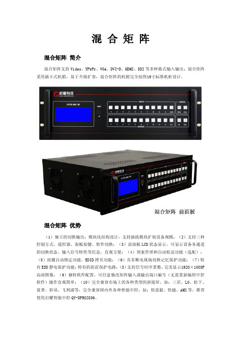
混合矩阵混合矩阵简介混合矩阵支持Video、YPbPr、VGA、DVI-D、HDMI、SDI等多种格式输入输出;混合矩阵采用插卡式机箱,易于升级扩容,混合矩阵的机箱完全按照19寸标准机柜设计。
混合矩阵优势(1)独立的切换输出;模块化结构设计,支持插拔模块扩展设备规模;(2)支持三种控制方式,遥控器、面板按键、软件切换;(3)前面板LCD状态显示,可显示设备各通道的切换状态、输入信号特性等信息,直观方便;(4)预案管理和自动轮巡功能(选配);(5)按键自动锁定功能,EDID拷贝功能;(6)具有断电现场切换记忆保护功能;(7)特有ESD静电保护功能;特有的防雷保护电路;(8)支持信号时序重整,完美显示1920×1080P 高清图像;(9)独特软件配置,可任意修改矩阵输入或输出端口编号(无需重新编程中控软件)操作直观简单;(10)完全兼容市场上的各种类型的拼接屏,如:三星、LG、松下、夏普、彩讯、飞利浦等,完全兼容国内外各种智能中控,如:快思聪、快捷、AMX等,推荐使用启耀智能中控QY-DPRO2806。
混合矩阵插卡板混合矩阵参数∙支持Video/VGA/YPbPr/DVI/HDMI/SDI等混合输入输出∙支持FULL现场EDID拷贝模式,操作简单,通俗易懂∙输入输出端强大的ESD,防雷击等保护电路,及时保护设备的正常运行∙输入内置信号采样放大电路,保证高清信号传输30米∙支持Video/VGA/YPbPr/DVI-D/HDMI/3G-SDI等输出板卡∙支持DVI-D/HDMI输出板卡信号格式转换,行场頻率转换∙支持USB控制,232控制,自带控制软件无需安装,可直接控制操作∙自带控制软件实现简体中文、繁体中文、英文等多种语言控制界面∙支持端口重定位:此功能适用我公司所有带232串口的切换设备∙支持产品过流,过压等保护电路设计;支持冗余电源配置∙切换速度:150ns(具体设备切换时间有所不同)∙串接接口:RS232,9孔D-Sub型连接器,端口2,3,5分别直通∙串口参数:9600bps、8位数据、1位起始位、1位停止位、无校验,无流控∙功耗:30~150W(视具体型号确定功耗)温度:0℃~60℃∙输入电压:AC100~240V;50/60Hz∙3U混切机箱尺寸:450×330×132mm(长×宽×高)约13Kg∙6U混切机箱尺寸:450×330×264mm(长×宽×高)约22Kg∙11U混切机箱尺寸:450×330×484mm(长×宽×高)约25KgVGA板卡VGA板卡:采用高性能专业处理芯片,实现信号分配或交叉切换等功能,输入自带缓冲设计,增强了现场抗干扰、防静电、防雷击等安全措施,使图像输出更加稳定清晰;设备自带信号延长,长距离传输失真补偿技术,保证信号长距离传输高保真输出;支持各种RGB、VGA、信号源,全贴片SMD工艺,特有ESD静电保护功能;安装简单,即插即用。
快思聪DM高清矩阵概述及应用方案参考
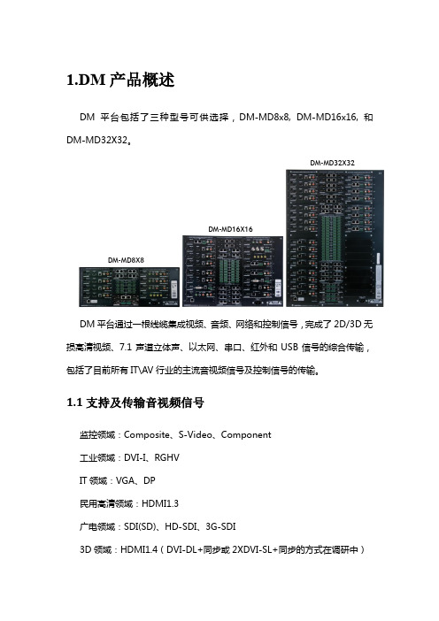
1.DM 产品概述DM 平台包括了三种型号可供选择,DM-MD8x8, DM-MD16x16, 和DM-MD32X32。
DM 平台通过一根线缆集成视频、音频、网络和控制信号,完成了2D/3D 无损高清视频、7.1声道立体声、以太网、串口、红外和USB 信号的综合传输,包括了目前所有IT\AV 行业的主流音视频信号及控制信号的传输。
1.1支持及传输音视频信号监控领域:Composite 、S-Video 、Component工业领域:DVI-I 、RGHVIT 领域:VGA 、DP民用高清领域:HDMI1.3广电领域:SDI(SD)、HD-SDI 、3G-SDI3D 领域:HDMI1.4(DVI-DL+同步或2XDVI-SL+同步的方式在调研中)DM-MD8X8DM-MD16X16DM-MD32X321.2传输介质与距离DM系统的传输介质采用CRESNTRON原厂电缆或市场上通用的双绞线或多模光纤,布线施工、管理、维护均相比传统方式简单。
使用超5类类屏蔽双绞线可提供高达100 m 的电缆传输距离。
使用OM3 50um万兆多模光纤可提供高达300 m 的电缆传输距离。
由于双绞线和光纤的价格便宜且施工方便,在系统设计之时可考虑充分的余量,在系统搭建完成之后,就无需为新增设备时为昂贵而且敷设困难的高清线缆而烦恼,DM平台的传输介质不管是光纤还是铜缆都能满足高清信号格式的传输。
1.3管理软件操控界面分为2D信号视频界面模块、3D信号视频界面模块、音频界面模块3大板块,结构从使用者角度出发,通过最合理简单的软件模块编排来完成对这套复杂系统的驾驭。
DM平台可由任何Crestron 2系列主机控制,通过触摸屏即可起送搞得完成信号的切换和处理,以及对系统状态以及输入输出信号的监视。
2.DM产品性能特点●提供带超高12.5 Gbps 背板数据速率的全矩阵切换●处理带Deep color、3D和高位速率7.1嵌入式音频的HDMI®●支持高达WUXGA 1920x1200 和高清1080p60的视频分辨率●使用DM 8G+™双绞线或者超五类屏蔽双绞线可提供高达330’(100 m)的电缆传输距离●使用单芯DM 8G光纤或者2芯可OM3 50um万兆多模光纤可提供高达1000’(300 m) 的电缆传输距离,单芯OM3 50um万兆多模光纤可传送500’(150 m)米距离。
高清混合矩阵
高清混合矩阵高清混合矩阵也称高清数字混合矩阵、DVI混合矩阵、HDMI混合矩阵、VGA混合矩阵。
YD系列混合矩阵可以支持定制视频、VGA、HDMI、DVI、 YpBpR、SDI等数字和模拟信号混合输入。
并将所有输入信号统一转换成VGA或DVI或HDMI信号,输出分辨率可以达到1920x1200,并满足矩阵切换的基功能。
深圳华天成是专业生产高清混合矩阵的厂家,集研发,生产,销售于一体。
致力于提供有价值的高清混合矩阵产品可根据您的要求为您量身定做,质估价更优。
在线咨询高清混合矩阵,获得个性化解决方案.深圳华天成高清混合矩阵是一款高性能的高清视频信号交换系统,该系统将高清视频信号切换控制、各类视频格式转换、传输以及网络远程管理等功能融合为一体,不但实现了模拟信号,数字信号的高清转换和路由功能,而且可以对视频信号进行补偿,修正,驱动等功能。
系统采用模块化设计、插板式结构、电源主板、MCU控制板、各种IO输入输出板卡均支持带点热拔插,易于维护、方便升级。
网络化管理实现了远程软件升级、远程控制、远程操控等功能。
具有RJ45、RS232和RS485控制接口。
主要用于可视指挥调度、电视台、高级会议室、控制室、监控室等。
随着技术进步,高清视频应用越来越广泛,标清、高清视频信号的视频格式多种多样,该设备为需要进行高清数字音视频切换、管理、控制的专业工程提供了一个独特的解决方案。
高清混合矩阵特点:1.模块化设计,插卡式结构,所有板卡支持热插拔,设备容量: 4×4~128×128;2.支持信号格式转换,支持倍频倍线转换功能,支持无缝切换;3.支持输入信号状态监测,能实时监测和显示当前各输入通道是否有效的信号接入;4.输入:VGA、DVI、YPbPr、CVBS、HDMI、HD-SDI、光纤LC、网线八种格式的信号;5.输出:VGA、DVI、YPbPr、CVBS、HDMI、HD-SDI、光纤LC、网线八种格式的信号;6.输入输出分辨率最大支持1920*1440,向下兼容1080P、720P信号等其他分辨率;7.可以将任意格式和分辨率的输入信号,统一为同一种分辨率的各种格式信号切换输出;8.支持输出信号字符叠加及拼接功能(选配);9.拥有中文图形化控制软件可通过RJ45网络和RS232进行电脑远程控制,支持中控控制,支持多通道同时切换,地址设置等功能;10.具有掉电记忆功能带有断电现场保护;11.双电源热备用,强制风冷,确保系统稳定运行。
派克系列高清数字混合矩阵
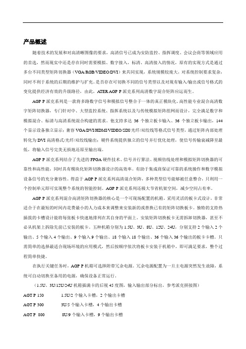
产品概述随着技术的发展和对高清晰图像的要求,高清信号已成为安防监控、指挥调度、会议会商等领域应用的首选,然而现实中还是存在同时需要模拟、数字接入,标清、高清接入的情况,原有的实现方式是通过多台不同类型矩阵切换器(VGA/RGB/VIDEO/DVI)来共同实现,系统规模较庞大,对系统控制要求复杂,同时不利于系统的后期的维护与扩充。
是否存在可切换不同的信号类型以及对现有输入/输出或信号格式的变化提供经济有效的升级路径,由此,A TER AGP-P派克系列高清数字混合矩阵应运而生。
AGP-P派克系列是一款将多路数字信号和模拟信号整合于一体的真正模块化、高性能专业混合高清数字矩阵切换器,专门针对中、大型监控系统、指挥系统以及与传统模拟矩阵组网而设计,完全满足数字和模拟混合、标清与高清系统混合构建的需求。
他支持多达36个独立板卡输入、36个独立板卡输出,144个显示设备独立显示;兼容VGA/DVI/HDMI/VIDEO/SDI/光纤/双绞线等格式信号类型,通过矩阵内部处理转化为DVI高清格式/光纤/双绞线输出;硬件系统提供独立的信号并行优化处理,使信号传输衰减降至最低,将输入信号完美无损地还原至输出端。
AGP-P派克系列结合了先进的FPGA硬件技术、信号并行算法、视频倍线处理和模拟矩阵切换器的可靠性和高性能,同时具有模块化矩阵切换器设计的高效率。
有助于集成商保证可靠的系统操作和数字模拟设备信号的充分兼容性。
得益于AGP-P派克系列高清混合矩阵,多种类型信号能够被任意整合,只利用一个控制单元即可实现整个系统的智能控制。
AGP-P派克系列还极大节省机架空间,减少空间占有率。
AGP-P派克系列混合高清矩阵切换器的核心是一个可现场配置的机箱,采用灵活的板卡式设计,非常适合于在最短的时间内花费最小的人力成本来调整来安装新的或替换已有的矩阵切换板卡。
独特的支持热插拔的卡槽设计能将每张板卡快速地排列在其自身的平面上。
安装矩阵切换板卡无需拆卸切换器,甚至不必从机架上拆除先前已安装的板卡。
天地伟业48进8出矩阵切换控制器软件说明书

Warning Statements多媒体控制软件需要安装在硬盘录像机上,才能实现对矩阵主机的控制管理,本说明书以天地伟业硬盘录像机为例进行介绍。
本机的设计和制造充分考虑了安装人员、操作人员以及辅助设备的安全问题,但不正确的安装和使用也可能引起触电伤人或漏电失火,在安装本机时,须考虑下述情况:一、安装1、安装前请打开包装先根据配件清单,清点包装内的配件是否齐全,如有缺损请及时向厂家或供货商提出,以免由于缺损导致设备无法正常工作;2.产品的安装调试应由专业人员操作或在专业人员指导下进行;3、安装时请考虑安放位置的环境因素,注意防尘、防水,远离高温的热源和环境,避免阳光直接照射;4、为确保硬盘录像机正常散热,应避开通风不良的场所,切勿堵塞硬盘录像机的通风口,机箱后部设计有散热风扇,因此安装时其后部应距离其它设备或墙壁5cm以上;5、硬盘录像机应水平安装,避免安装在会剧烈震动的场所;6、第一次使用前请认真阅读说明书的快速入门部分,避免由于使用不当造成设备无法正常使用或损坏;7、切记不要尝试自己拆盖维修,以免造成设备损坏;8、请使用原厂配件或由制造商推荐的配件。
二、避免电击和失火1、切记勿用湿手触摸电源和硬盘录像机;2、勿将液体溅落在硬盘录像机上,以免造成机器内部短路或失火;3、勿将其它设备直接放置于硬盘录像机上部;4、当硬盘录像机的电源线与电源插座连接后,即使未启动,机器内部仍有电压,所以必须确保电源线与电源插座脱离后才可打开机箱盖。
三、运输与搬运1、本机的包装经过抗震设计和实验,搬运时,最好使用原来的包装材料和纸箱;2、运输装有硬盘的录像机时,务必将硬盘安装在硬盘架中,并用螺丝固定,否则可能会造成硬盘损伤而不能正常工作;3、避免在过冷、过热的场所间相互搬动录像机,以免机器内部产生结露,影响机器的使用寿命;4、严禁带电搬动本机,否则会损坏硬盘和主板。
四.特别注意:在使用时,我们特别提醒,硬盘录像机在带电状态下:1.不能直接插拔硬盘;2、不能直接插拔音视频线、串口线;3、不能直接带电插拔解码器、报警解码器及球型摄像机设备连线。
8进8出VGA矩阵
应பைடு நூலகம்领域
矩阵切换器类产品作为专业、多元化的信号管理设备,在信号系统中起到了信号调度作用,并作为系统中的 核心设备。该类产品广泛用于广播电台,电视台,有线络,电视会议,交通管理,军事指挥,平安城市,武警消 防等需要进行信号管理和调度的领域,完成信号切换,管理、调度等功能。为视/音频信号的灵活运用,提供了经 济实用的解决方案。随着多媒体技术的大量普及,在矩阵切换器类产品中也融入了多媒体元素,这类矩阵切换器 广泛应用于教育,多媒体会议,多功能厅,大型展厅,娱乐场所,舞台演出,计算机应用等行业。
连接图例
VGA矩阵系统连接图 信号源接VGA矩阵输入端 VGA矩阵输出端接显示设备
故障维护
1)当VGA矩阵所接外设投像有重影,如投影机有重影时,一般不是主机问题,可能是投影机没有正确调好, 应对投影机相应按钮进行调节。
2)当出现颜色丢失或都无视频信号输出,可能是VGA头没接好。 3)当遥控器不能控VGA矩阵时: a.可能是电池没电了,请更换电池; b.可能是遥控器坏了,请维修。 4)当串口(一般指:电脑串口)控制不了VGA矩阵时,看软件串口是否与所接设备串口对应。 5)如果VGA矩阵输入输出信号能切换,但没有bb叫声,可能主机内部蜂鸣器坏了,请送专业人员进行维修。 6) VGA矩阵切换时,蜂鸣器有响声,但无相应投像输出: a.看相应的输入端是否有信号。(可用示波器或万用表进行检测)如果没有信号输入,有可能是输入接线断 了,或接头松了,更换接线即可。 b.看相应的输出端是否有信号。
开发设计
VGA矩阵的RGB交叉矩阵主要采用美国模拟器件公司生产的AD8108/AD8109,不仅集成了许多分立元件实现的 功能,而且使用寿命长、电磁兼容性好、扩展性好;VGA矩阵的行场交叉属于数字信号,大部分厂家使用CPLD可 编程逻辑器件。
yeren矩阵8进8出切换器使用说明
yeren矩阵8进8出切换器使用说明摘要:1.概述2.功能与特点3.使用方法4.注意事项5.结束语正文:一、概述yeren 矩阵8 进8 出切换器是一款高性能的矩阵切换设备,适用于各种音视频信号的切换和分配。
它具有8 路输入和8 路输出,支持多种信号格式,可广泛应用于会议室、教学系统、家庭影音、监控系统等领域。
二、功能与特点1.高性能:yeren 矩阵8 进8 出切换器采用高品质的芯片和先进的工艺制造,具备出色的信号传输性能和稳定性。
2.广泛兼容:该切换器支持多种信号格式,如VGA、HDMI、DVI、Audio 等,满足不同应用场景的需求。
3.灵活切换:用户可以通过遥控器、面板按键或者RS-485 控制信号的切换,操作简单便捷。
4.智能保护:设备具备智能检测和保护功能,能够自动检测信号并进行相应的保护,确保设备运行安全可靠。
三、使用方法1.连接线路:根据需要将输入设备(如电脑、摄像机等)连接到切换器的输入端口,将输出设备(如投影仪、监视器等)连接到切换器的输出端口。
2.启动设备:分别开启输入设备和输出设备,确保它们处于正常工作状态。
3.操控切换:使用遥控器、面板按键或者RS-485 控制设备进行信号切换,实现不同信号之间的自由切换。
4.调整参数:如需调整信号的显示效果,可进入设备的菜单界面进行相关参数的设置。
四、注意事项1.在使用过程中,请勿将设备暴露在潮湿、高温或者强磁场环境中,以免影响设备的正常运行。
2.在进行连接时,请确保各接口的连接正确无误,避免因接错线导致的设备损坏。
3.如遇到问题,请勿自行拆卸设备,以免造成不必要的损坏。
建议联系专业技术人员进行处理。
五、结束语yeren 矩阵8 进8 出切换器凭借其优异的性能、广泛的兼容性、灵活的切换方式以及智能保护功能,成为了音视频信号切换设备的理想选择。
8X8点阵
8X8点阵的实际外观图如下:一共64个发光点构成,上下两排引脚,每排8个,一共16个点阵侧面有文字的那面对准自己,(图1)8X8点阵的显示原理:8X8点阵共由64个发光二极管组成,且每个发光二极管是放置在行线和列线的交叉点上,当对应的某一行置1电平,某一列置0电平,则相应的二极管就亮;如要将第一个点点亮,则1脚接高电平a脚接低电平,则第一个点就亮了;如果要将第一行点亮,则第1脚要接高电平,而(a、b、c、d、e、f、g、h)这些引脚接低电平,那么第一行就会点亮;如要将第一列点亮,则第a脚接低电平,而(1、2、3、4、5、6、7、8)接高电平,那么第一列就会点亮.(图2)8*8点阵实际的引脚(图一)的不是一排阳极,一排阴极,(就像键盘一样不是abcd按顺序排的)所以焊接有点麻烦,8×8LED点阵引脚图如下:1,2,3,4,5,6,7,8是行(阳极)a,b,c,d,e,f,g,h是列(阴极)//此处说的都是行阳型8*8点阵,行阴的略外面的1~16就是实际的管脚,见图一移位锁存器74HC595原理74HC595是一个串入并出的芯片,通过一个for(i=0;i<8;i++)来存储数据。
具体来说就是第一个时钟信号来到时低位的数据向高位挪动一位,在这个程序中是SH_CP 信号,当SH_CP是一个上跳沿时,传入的形参Data与0x80相与,得到的数为1,则通过SDATA置1,否通过置为0, 并存储在74HC595的相应位置(最低位即Q0那)上,DS内部也自动左移一位数据然后dat向左移一位,使次高位变为最高位与0x80相与,并存储。
通过8次后,就可以得到数据,并存储在Q0~Q7中了,这时ST_CP一个上跳沿,数据即送出去了.与8*8LED连接如下:显示0~59C语言代码:#include<AT89X52.h>#define uchar unsigned char#define uint unsigned intvoid Ser_IN(uchar Data){uchar i;for(i=0;i<8;i++){SH_CP=0; //先置为低DS=Data&0x80;//取数据的最高位Data<<=1; //讲数据的次高位移到最高位,为下一次取数据做准备SH_CP=1; // 再置为高,产生移位时钟上升沿,储存器里的数据移位,数据输入}}void Par_OUT(void){ST_CP=0; //先置为低ST_CP=1; //再置为高,产生时钟上升沿,上升沿时,数据并行输出}uchar code tab[]={0xfe,0xfd,0xfb,0xf7,0xef,0xdf,0xbf,0x7f}; //列uchar code tabdigit[60][8]={ //字模取模方向阴码逆向逐列式{0x00,0x3E,0x41,0x41,0x3E,0x00,0x00,0x00},{0x00,0x42,0x7F,0x40,0x00,0x00,0x00,0x00},{0x00,0x62,0x51,0x49,0x46,0x00,0x00,0x00},{0x00,0x22,0x49,0x49,0x36,0x00,0x00,0x00},{0x00,0x38,0x26,0x7F,0x20,0x00,0x00,0x00},{0x00,0x4F,0x49,0x49,0x31,0x00,0x00,0x00},{0x00,0x3E,0x49,0x49,0x32,0x00,0x00,0x00},{0x00,0x03,0x71,0x09,0x07,0x00,0x00,0x00},{0x00,0x36,0x49,0x49,0x36,0x00,0x00,0x00},{0x00,0x26,0x49,0x49,0x3E,0x00,0x00,0x00},{0x02,0xFF,0x00,0x00,0xFF,0x81,0xFF,0x00},{0x02,0xFF,0x00,0x02,0xFF,0x00,0x00,0x00},{0x02,0xFF,0x00,0xF3,0x91,0x99,0xCF,0x00},{0x02,0xFF,0x00,0x42,0x89,0x89,0x89,0x76},{0x02,0xFF,0x00,0x1C,0x13,0x10,0xFF,0x10},{0x02,0xFF,0x00,0x4F,0x89,0x89,0x89,0x71},{0x02,0xFF,0x00,0x7C,0x92,0x91,0x91,0x60},{0x02,0xFF,0x00,0x01,0xF9,0x05,0x03,0x00},{0x02,0xFF,0x00,0x76,0x89,0x89,0x89,0x76},{0x02,0xFF,0x00,0x4E,0x91,0x91,0x91,0x7E},{0xE2,0x91,0x89,0x86,0x00,0xFF,0x81,0xFF},{0xE2,0x91,0x89,0x86,0x00,0x02,0xFF,0x00},{0x79,0x49,0x4F,0x00,0x7A,0x4A,0x4E,0x00},{0x79,0x49,0x4F,0x00,0x49,0x49,0x49,0x36},{0x79,0x49,0x4F,0x00,0x1E,0x10,0xFF,0x10},{0x79,0x49,0x4F,0x00,0x4E,0x4A,0x7A,0x00},{0x79,0x49,0x4F,0x00,0xFE,0x92,0x92,0x60},{0x79,0x49,0x4F,0x00,0x79,0x05,0x03,0x00},{0x79,0x49,0x4F,0x00,0x76,0x89,0x89,0x76},{0x79,0x49,0x4F,0x00,0x4E,0x91,0x91,0x7E},{0x42,0x89,0x89,0x76,0x00,0xFE,0x82,0xFE},{0x42,0x89,0x89,0x76,0x00,0x02,0xFF,0x00},{0x42,0x89,0x89,0x76,0x00,0xF9,0x89,0x8F},{0x42,0x89,0x89,0x76,0x00,0x89,0x89,0xFF},{0x42,0x89,0x89,0x76,0x00,0x0F,0x08,0xFF},{0x42,0x89,0x89,0x76,0x00,0x9E,0x92,0xF2},{0x42,0x89,0x89,0x76,0x00,0xFF,0x89,0xF9},{0x42,0x89,0x89,0x76,0x01,0x01,0xFD,0x03},{0x42,0x89,0x89,0x76,0x00,0xFF,0x89,0xFF},{0x42,0x89,0x89,0x76,0x00,0xCF,0x89,0xFF},{0x1F,0x10,0xFF,0x00,0x7E,0x81,0x81,0x7E}, {0x1F,0x10,0xFF,0x00,0x02,0xFF,0x00,0x00}, {0x1F,0x10,0xFF,0x00,0xE2,0x91,0x89,0xC6}, {0x1F,0x10,0xFF,0x00,0x42,0x89,0x89,0x76}, {0x1F,0x10,0xFF,0x00,0x1E,0x10,0xFF,0x10}, {0x1F,0x10,0xFF,0x00,0x8F,0x89,0x89,0xF9}, {0x1F,0x10,0xFF,0x00,0xFF,0x89,0x89,0xF9}, {0x1F,0x10,0xFF,0x00,0x03,0xF9,0x05,0x03}, {0x0F,0x08,0xFF,0x00,0x76,0x89,0x89,0x76}, {0x1F,0x10,0xFF,0x00,0x4E,0x91,0x91,0x7E}, {0x4F,0x49,0x79,0x00,0x3E,0x41,0x41,0x3E}, {0x4F,0x49,0x79,0x00,0x00,0x02,0x7F,0x00}, {0x4F,0x49,0x79,0x00,0x62,0x51,0x49,0x46}, {0x4F,0x49,0x79,0x00,0x42,0x89,0x89,0x76}, {0x4F,0x49,0x79,0x00,0x1E,0x10,0x7E,0x10}, {0x4F,0x49,0x79,0x00,0x4F,0x49,0x79,0x00}, {0x4F,0x49,0x79,0x00,0x7F,0x49,0x79,0x00}, {0x4F,0x49,0x79,0x00,0x01,0x7D,0x03,0x01}, {0x4F,0x49,0x79,0x00,0x76,0x89,0x89,0x76}, {0x4F,0x49,0x79,0x00,0x0E,0x91,0x91,0x7E}, };uint timecount;uchar a;uchar b;void main(void){TR0=0;TMOD=0x01;TH0=(65536-1000)/256;TL0=(65536-1000)%256;EA=1;ET0=1;TR0=1;while(1);}void t0(void) interrupt 1{TH0=(65536-1000)/256;TL0=(65536-1000)%256;Ser_IN(tab[a]); //8X8点阵列扫描Ser_IN(tabdigit[b][a]);//送行扫描数据Par_OUT(); //显示a++;if(a==8){a=0;}timecount++;if(timecount==1000){timecount=0;b++;if(b==60){b=0;}}}最近接触了74164的相关知识,在做项目的过程中多次用到这个芯片,现在就写一下个人对此芯片使用方法的总结.图1 引脚图图2 引脚定义图3 真值表引脚介绍: A/B 为输入引脚,通常是两个引脚连在一起,接入单片机的一个引脚上.CLOCK为时钟输入,上升沿采集输入引脚A/B/CLEAR 主机复位引脚,低电平时候复位所有输出引脚QA to QH 输出引脚在真值表中可以看出,只有当/CLEAR为高电平时且时钟为上升沿的时候才可采集输入引脚状态,若A/B同为高则输出为高,否则只要A/B中任意一个为底的则输出为低..大家在使用的时候只要知道这一点就可以了.下面给出一个例子看看上图为164扩展按键使用的电路图DATA,CLK1,分别于单片机的引脚相连,DATA用于输入数据,clk用于时钟输出.看看我写的相关函数吧/*---------------------------------/读取data数据的最低位的值/---------------------------------*/bit checksbit(unchar date){return (date&0x01);}/*---------------------------------/向74164中写入数据函数参数:date:写入的数据函数返回:无/---------------------------------*/void senddata1(unchar date){unchar n;for(n=0;n<8;n++){if(checksbit(date)==0)CLK_DATA=0;elseCLK_DATA=1;CLK1=0;CLK1=1;date>>=1;}}注意单片机的时钟频率,74164的时钟输入是由要求的,不能大于其要求输入的最大值,如果单片机的频率过大,可能会产生错误,这个大家根据自己的实际情况去决定.。
锐酷电子 8x8 HDMI 矩阵器与分析器及 4K-to-1080P 下调器 用户指南说明书
To reduce the risk of fire or electric shock, read and follow all instructions and warnings in this manual. Keep this manual for future reference.1. Do not expose this apparatus to rain or moisture. Do not expose this equipment to drippingor splashing, and ensure that no objects filled with liquids, such as vases, are placed on the equipment. Do not use this apparatus near water.2. Do not remove cover. No user serviceable parts inside.3. Clean only with a dry cloth.4. Do not block any ventilation openings. Install according to manufacturer’s instructions.5. Do not install near any heat sources such as radiators, heat registers, stoves or otherapparatus (including amplifiers) that produce heat.6. Do not override the safety purpose of the polarized or grounding plug. A polarized plug hastwo blades, one of which is wider than the other. A grounding plug has two matching blades and a third grounding prong. The wide blade or the third prong is provided for your safety. If the provided plug does not fit into your outlet, consult an electrician for replacement of the obsolete outlet.7. Protect the power cord from being walked on or pinched, particularly at the plug end andwhere the power cord is attached to the apparatus.8. Only use attachments and accessories specified by the manufacturer.9. Refer all servicing to qualified service personnel. Servicing is required when the apparatushas been damaged in any way, such as when the power supply cord or plug is damaged, liquid has been spilled on or objects have fallen into the apparatus, the apparatus hasbeen exposed to rain or moisture, the apparatus does not operate normally, or it has been dropped.10. To completely disconnect this equipment from power, disconnect the power supply cordfrom the power outlet.The lightning flash with arrowhead symbol, within an equilateral triangle, is intended to alert the user to the presence of uninsulated dangerous voltage within the product’s enclosure that may be of sufficient magnitude to constitute a risk of electric shock to persons.The exclamation point within an equilateral triangle is intended to alert the user to the presence of important operating and maintenance (servicing) instructions in the literature accompanying the appliance.2This equipment has been tested and found to comply with the limits for a Class B digital device, pursuant to Part 15 of the FCC Rules. These limits are designed to provide reasonable protection against harmful interference in a residential installation. This equipment generates uses and can radiate radio frequency energy and, if not installed and used in accordance with the instructions, may cause harmful interference to radio communications. However, thereis no guarantee that interference will not occur in a particular installation. If this equipment does cause harmful interference to radio or television reception, which can be determined by turning the equipment off and on, the user is encouraged to try to correct the interference by one or more of the following measures:• Reorient or relocate the receiving antenna.• Increase the separation between the equipment and receiver.• Connect the equipment into an outlet on a circuit different from that to which the receiver is connected.• Consult the dealer or an experienced radio/TV technician for help.Changes or modifications not expressly approved by the party responsible for compliance could void the user’s authority to operate the equipment.31. Product Overview (5)2. Features (5)3. Package Contents (5)4. Device Layout (6)4.1. B-660-MTRX-8x8 Front Panel (6)4.2. B-660-MTRX-8x8 Rear Panel (6)5. Installation & Wiring (7)5.1. Installation (7)5.2. Wiring (7)6. RS232 Control (8)7. IR Remote Control (9)8. Web UI Control (9)8.1. Get Access to the Web UI (9)8.2. Web UI Introduction (10)9. Specifications (18)9.1. Transmission Distance (19)10. Warranty (19)11. Support (19)41.B-660-MTRX-8x8 is an 8x8 HDMI 2.0 Matrix with resolutions supported up to 4K@60Hz 4:4:4 8bit and HDCP 2.2 compatibility. It allows eight sources to be switched to eight HDMI displays simultaneously. The B-660-MTRX-8x8 supports various HDR formats including HDR10, HLG and Dolby Vision up to 4K60, and ARC for residential applications. It also allows for flexible video output in mixed 1080P and 4K TV environments, by providing 4K-to-1080P simple downscaler with each HDMI output. B-660-MTRX-4x4 Matrix can be controlled by IR, RS232 and LAN control with Telnet API and Web UI.Designed for 1U rack mount and stand-alone installation, this matrix offers an Ultra HD A/V switching and distribution solution ideal for a variety of applications, such as offices, schools, conference rooms, hotels, etc. .2.• Includes 8 HDMI inputs and 8 HDMI outputs.• Inputs and outputs support video resolutions up to 4K@60Hz 4:4:4 8bit and HDCP 2.2. • Supports 4K@60Hz HDR formats, including HDR10, HLG & Dolby Vision.• Fast switching among multiple video sources.• Provides independent 4K-to-1080P simple downscaler with each HDMI output.• Provides rich audio output modes:>Supports HDMI de-embedded audio from associated HDMI output.>Supports ARC audio return via associated HDMI output(in this case the HDMI output must be connected to TV’s HDMI ARC port).• Provides ready-to-use RCA analog ports for all audio outputs and 5-pin true differentialbalanced audio ports for audio outputs 7&8.• Supports IR, RS232 and LAN (Telnet API & Web UI) control options.• OvrC enabled.3.• 1 x B-660-MTRX-8x8 Matrix• 1 x AC Power Cord with US Pins• 1 x IR Remote• 2 x Phoenix Connectors (3.5mm, 5 Pins)• 1 x Phoenix Connector (3.5mm, 3 Pins)• 2 x Mounting Brackets (with Screws)• 1 x Installation Manual54.4.1. B-660-MTRX-8x8 Front Panel1. Output Channel IndicatorIndicates input for output port 1-8.2. IR WindowReceives signals from IR remote.3. STATUS LEDOn: The device is connected to the network.Off: No network is connected to the device.4. Power SwitchPress to power on/off the matrix.4.2. B-660-MTRX-8x8 Rear Panel1. HDMI IN (1-8)Connect to HDMI Sources.2. HDMI OUT (1-8)Connect to HDMI displays.3. AC 100-240V 50/60HzConnect the power cord provided. Accepts AC power of 100-240V 50/60Hz.4. LANConnect to a control system for Web UI or Telnet control.5. RS-232Connect to a control PC or control system for RS232 serial control.6. AUDIO OUT 1-8L/R analog output (1-8): L/R analog audio output. Connect to audio devices via RCA stereo6audio cables;Phoenix Connector Audio output (7-8): 5 pins, 3.5mm phoenix connector. Connect to audio devices via 5pins, 3.5mm phoenix stereo audio cables.Note: Audio output ports can be set through web UI or API commands to output HDMIde-embedded audio, or ARC audio from associated HDMI output connected TVs (with ARC function supported, and the CEC function is set to on)5.5.1. InstallationB-660-MTRX-8x8 occupies 1U space and can be placed on a solid and stable surface or installed on a standard equipment rack.Steps to install the matrix on an equipment rack:1. Attach the installation bracket to the enclosure using the screws provided in the packageseparately.The bracket is attached to the enclosure as shown.2.3. Repeat steps 1-2 for the other side of the unit.4. Mount and affix the unit in the rack mount with the mounting screws.5.2. WiringWarnings:• Before wiring, disconnect the power from all devices.• During wiring, connect and disconnect the cables gently.Steps for device wiring:1. Connect HDMI INConnect the HDMI sources (such as PC, Blu-ray player, Apple TV, 4K media player, etc) to the HDMI IN 1-8 of the Matrix.72. Connect HDMI OUTConnect HDMI display device (such as TV, projector, LED/LCD display) to the HDMI OUT 1-8.3. Connect AUDIO OUTConnect audio devices to AUDIO OUT 1-8 of the Matrix (e.g. audio amplifier).4. Connect for additional control options:• LAN Control (Telnet/Web UI): Connect a Local Area Network to the LAN port of the Matrix.• RS232 Control: Connect a control PC or control system to RS-232 port of the Matrix.• IR Control: The IR Remote provided is for controlling the Matrix through IR signal.5. Connect the AC power cord provided to the Matrix.6. Power on all attached devices.Application Diagram6.Advanced users may need to control the matrix through RS232 serial communication. Connect a control PC or control system to the RS-232 port of the receiver. API command for RS232 control is available in the separate document “API Command Set_ B-660-MTRX-8x8”. A professional RS232 serial interface software (e.g. Serial Assist) may be needed as well.Before executing the API command through RS232 serial connection, please ensure RS232 interface of the device and the control PC are configured correctly.897.The Matrix can be controlled by the IR Remote provided. Point the Remote directly to the IR window on front panel of the Matrix. Now you can select input source for each output display.Next InputPrevious InputOutput 2To select input source for output display:1. Locate the target output you want to switch inputs for, numbered 1-8 vertically along the right side.2. Press the previous ( ) or next ( ) button to select the desired input source.A complete list of hex IR codes can be found in the “B-660-MTRX-8x8_IR Code” file.8.The Web UI designed for the matrix is available for basic controls and advanced settings of the device. The Web UI can be accessed through a browser, e.g. Chrome, Firefox, Safari, Opera, IE, etc..The default network mode of matrix is DHCP , in this mode, if there’s not a DHCP server, the matrix supports for a local 169.254.xxx.xxx IP address.8.1. Get Access to the Web UI1. Connect the LAN port of the matrix to your PC using a straight UTP cable, or connect the matrix to a local area network, and connect your PC to the same network. Using the later connection, ensure a DHCP server is included in the local area network.102. Use a tool such as OvrC to search the IP address of the device or send API command to get IP address (More information, see the separate document “API Command Set_B-660-MTRX-8x8”). Set your PC to the same network segment as the matrix if you connect the matrix to your PC directly.3.Input the IP address in your browser and press Enter. The following window will display.Enter the Username and Password. The default username and password are both “binary”. Then click “Login”. When login firstly, the following page will be popped up to remind you tochange the username and password.Note:• The changed username and password must be different from the default username and password.• Username and Password must be 4 to 16 characters in length, alphanumeric only.8.2. Web UI IntroductionThe web UI page includes the following submenus: SIGN OUT, FACTORY DEFAULT, UPDATE and REBOOT on the up-right corner, Matrix Control, Log and System in the main page.8.2.1.SIGN OUTClick the icon to return to the login page.8.2.2.FACTORY DEFAULTClick the icon, the following window will be popped up, click “CONFIRM” to reset the device tofactory default.UPDATE8.2.3.Click the icon, enter the following window.1112Click “BROWSE” to select the needed upgrade file (“.zip” file is need, you can upload ARM,MCU, or web UI upgrade file), and then click “UPDATE” to upgrade the corresponding firmware.Note: Do not power off the device when upgrading.8.2.4.REBOOTClick the icon, the follwing window will be popped up, click “CONFIRM” to reboot the device.Note: Please wait at least 2 minutes to refresh the web page and log in again.8.2.5. Matrix ControlMove the mouse to “Matrix Control” in the web page, it shows the following sub-menus: Switch and preset, Configuration and Display control. Click the item you want to configure.1. Switch and preseta. Video ControlThis section manages distribution of input video sources to output displays. Click the button in the table to select the input for the output display (button turns from white to blue once selection is done).13• All Outputs: Click to route one input to all outputs.• None: None input is routed to the output (or the output is turned off).By default, Video Input 1 routes to Output 1, …, Video Input 7 routes to Output 7, Video Input 8 routes to Output 8.b. Audio ControlThis section allows you to select audio source for each audio output.• HDMI de-embed: AUDIO OUT port outputs De-embedded audio from the corresponding HDMI OUT port.• HDMI ARC: AUDIO OUT port outputs ARC audio from the corresponding HDMI OUT port.The default setting for each audio output is HDMI de-embed.c. PresetsThis section saves/loads the input/output switch settings to or from the Matrix.• SAVE: Settings in Video Matrix Control section are saved.• LOAD: Preset already saved is loaded.142. ConfigurationThis section allows you to change name for each input and output, set EDID for each input, andshow video and audio informations for each inputs and outputs.• Input/Output: Select one input/output to set and show its video and audio informations.• Input Name/Output Name: Redefine the input/output names.For Input:• EDID: Click to select the EDID for input.>Apply: Click to make the EDID setting take effect. >ExportEDID: Click to save the EDID information of the selected input port as a bin fileto local PC.• Video In/Audio In: Show the video and audio informations for selected inputs.15For Output:• ExportEDID: Click to save the EDID information of the TV connected to the selected output port as a bin file to local PC.• Video Out/Audio Out: Show the video and audio informations for selected outputs.3.Display Control• Display On: Click to send the saved Display On command to the connected CEC-enabled display to power on it immediately.• Display Off: Click to send the saved Display Off command to the connected CEC-enabled display to power off it immediately.• Auto On/Off: Click to enable or disable the CEC Auto Control. By default, the auto CEC control is on.• Delay Time (1~30min): Click the up/down arrow to set the time for the display to power off automatically when no signal is present. For example, if Auto control is set as on and the time is set to 2 minutes, the output display will power off automatically when there’s no signal at the display for 2 minutes.8.2.6. Log1. API TestThis section allows you to input API commands to control the matrix.• Send: Click to send the command entered to the matrix.Note:• More API commands, please refer to the separate document “API Command Set_B-660-MTRX-8x8”.16•The return information of the sent command will be shown in log box:2. LogThis section shows the operation log and return information of the tested command.• Export Log: Click to export omni log recording information for remote trouble shooting.8.2.7. SystemMove the mouse to “System” in the page, it shows the following sub-menus: Information, Network and Other. Click the item you want to configure.1. InformationThis section shows the basic information of the matrix, including MODEL, SERVICE NUMBER,SERVICE TAG, MAC ADDRESS, IP ADDRESS and FIRMWARE VERSION.2. NetworkNetwork is used to set between the static and dynamic IP address.17• DHCP: When enabled, the IP address of the Matrix is assigned automatically by the DHCP server connected.• Static: When enabled, set up the IP address manually.• Apply: Click to enable the network setting.Note:• When “Static” is selected, please ensure your PC is in the same network segment as the Matrix, i.e. the IP address of your PC should be set as 192.168.xxx.xxx.• Please wait for 2-3 minutes for the Matrix’s LAN module to reboot and reconnect after the network setting is changed.By default, the IP type is set as DHCP . If it doesn’t have DHCP server, the matrix supports for local IP address. Use API Command to get the IP address.3.Othera. Power Saving ModeThis section allows you to set power saving mode of the matrix to on/off. The default setting isoff.Note: When set Power Saving Mode to on, the matrix will enter standby mode to use lesspower than normal operation mode. In this mode, the front panel display will be off, and outputs will the powered down.18b. Login UsernameThis section is where to change the Username.• Apply: Click to make the setting take effect.Note: User name must be 4 to 16 characters in length, alphanumeric only.c. Login PasswordThis section is where to change Password.• Apply: Click to make the setting take effect.Note: Password must be 4 to 16 characters in length, alphanumeric only.9.199.1.Transmission Distance10. WARRANTY2-Year Limited WarrantyThis Binary product has a 2-Year limited warranty. This warranty includes parts and labor repairs on all components found to be defective in material or workmanship under normal conditions of use. This warranty shall not apply to products that have been abused, modified or disassembled. Products to be repaired under this warranty must be returned to SnapOne or a designated service center with prior notification and an assigned return authorization number (RA).11. SUPPORTNeed Help? Contact Tech Support!If you need further clarification, please call tech support at (866) 838-5052, or email ***********************. For other information, instructional videos, supportdocumentation, or ideas, visit our website and view your item’s product page at .Rev: 220418-160923© 2022 Binary。
混合矩阵知识点
混合矩阵知识点混合矩阵(Confusion Matrix)是在机器学习和模式识别领域中常用的一种评估分类模型性能的工具。
通过混合矩阵,我们可以直观地了解模型在不同类别上的分类表现,进而进行模型调优和改进。
本文将逐步介绍混合矩阵的相关概念和计算方法。
步骤一:理解混合矩阵的基本概念混合矩阵是一个二维矩阵,行列分别代表真实标签和预测标签。
在一个二分类问题中,混合矩阵通常是一个2x2的矩阵,如下所示:预测正例预测反例真实正例TP FN真实反例FP TN其中,TP(True Positive)表示真实为正例且被预测为正例的样本数;FN (False Negative)表示真实为正例但被预测为反例的样本数;FP(False Positive)表示真实为反例但被预测为正例的样本数;TN(True Negative)表示真实为反例且被预测为反例的样本数。
步骤二:计算混合矩阵的常见指标基于混合矩阵,我们可以计算一些常见的分类性能指标来评估模型的性能。
下面是几个常见的指标:1.准确率(Accuracy):准确率是指分类正确的样本数占总样本数的比例。
计算公式为:准确率 = (TP + TN) / (TP + FN + FP + TN)。
2.精确率(Precision):精确率是指被正确预测为正例的样本数占所有预测为正例的样本数的比例。
计算公式为:精确率 = TP / (TP + FP)。
3.召回率(Recall):召回率是指被正确预测为正例的样本数占所有真实为正例的样本数的比例。
计算公式为:召回率 = TP / (TP + FN)。
4.F1值(F1-Score):F1值是精确率和召回率的调和平均数,综合考虑了这两个指标的性能。
计算公式为:F1值 = 2 * (精确率 * 召回率) / (精确率+ 召回率)。
步骤三:解读混合矩阵混合矩阵不仅可以计算各种性能指标,还能帮助我们直观地理解模型在各类别上的分类表现。
1.对角线上的元素(TP和TN)表示模型正确分类的样本数,对角线元素越大,模型性能越好。
高清视频混合矩阵
高清视频混合矩阵现代会议室常用的视频设备包括高清数字摄像机、高清录播机、蓝光高清DVD、高清视频会议终端、高清视频矩阵、高清液晶电视、高清投影机等;同时还有多种视频接口:AV、VGA、RGBHV、YPBPR、DVI、HDMI、HD- SDI等。
如此繁复的设备以及各不相同的接口,给系统设计人员增加了很大设计难度。
基于市场客观需求,深圳华天成为各行业设计了一款高清视频混合接口矩阵。
该高清视频混合矩阵具有如下设计特点:1、支持多种视频接口的输入,包括VGA、YPBPR、AV、SDI、HDMI、DVI的输入,支持HDMI、DVI、HD-SDI 全高清输出;2、输入输出可以自由切换;3、采用模块化设计,客户可以根据不同的会议室,对视频传输系统的输入和输出做到最佳资源配置,减少资源浪费;4、具有多种介质传输的优势,可以支持普通的铜线传输、网线传输、光纤传输;5、每个板卡可以做到视频接口的自由配置,便于设备运行中的硬件升级;6、紧凑型结构设计,减少资源浪费。
华天成高清视频混合矩阵优化资源配置与硬件升级,极大简化了传输系统,降低了系统成本,同时也降低了安装维护工作量,提高了系统的稳定性和可靠性。
华天成高清视频混合矩阵应用拓扑图:上图是华天成某客户视频会议主会场高清矩阵系统拓扑图,该视频源设备信号种类非常复杂,有SDI 摄像机、VGA电脑、AV的电视机顶盒、HDMI的蓝光高清DVD、视频终端等设备,需要将这些信号按需切换到会场中的4台55英寸高清液晶电视、投影机以及会议室监控显示器中显示,同时需要将两路高清双流会议信号输出给终端和录播设备。
该项目应用华天成高清混合矩阵,配合相应的SDI/VGA/AV/HDMI信号类型输入卡,实现了原有3台矩阵与转换器(VGA/SDI/HDMI)才能够实现的功能。
而且会场的显示设备与机房中的矩阵间平均距离超过40米,矩阵配备了相应网线与光输出卡,轻松解决了传输问题。
从上图中可以直观地看到该混合接口系统优势:各种信号直接接入矩阵,无需转换器,安装维护方便;网线与光纤直接接入矩阵,无需传输设备或中继设备,布线方便;插卡式设计,方便更换升级。
4K Ultra-HD 8x8 HDMI矩阵交换器说明书
Distribute eight 4K HDMI sources to eight local monitors and eight remote displays via HDBaseT (CAT5e/6/7)with IR and TCP/IP control support.FEATURES• Up to 4K (3840x2160 @30Hz) Resolution • (8) HDMI Input• (8) HDMI Local Output• (8) HDMI HDBaseT Output (over CAT5e/6/7)• Supports Power-over-Ethernet (POE)• HDBaseT signal extension up to 328 ft• Ethernet routing: connect output displays to internet via CAT5e/6/7 HDBaseT.•HDMI 1.4 & HDCP CompliantAPPLICATIONS4K /2K• Route RS-232 control to remote monitors • Supports bi-directional IR remote control • Supports TCP/IP Web Console control • EDID learning & management• Supports HDX-POE receivers: Video & IR extension (sold seperately)•Supports HDX-POE-PRO receivers: video, IR, RS-232, and Ethernet extension (sold separately)• Sports Arenas • Concert Halls• Cinemas & Multiplex Theaters •Convention Centers• Hotel Lobbies• Transportation Hubs (Airports, Train Stations)• Lecture Halls & Auditoriums •and more!4K Ultra-HD 8X8 HDBaseT HDMI Matrix with POEHDR-8x8-XTOVERVIEWThe HDR-8x8-XT is an 8x8 matrix switch that sends 4K (3840x2160 @30Hz) HDMI signals to output devices up to 328 ft away with HDBaseT CAT5/6/7 extension.Ideal for large venues with multiple 4K-ready screens, the HDR-8x8-XT offers unmatched performance and quality over considerable distances. Arenas, movie theaters, concert venues, nightclubs, event halls, convention centers, and more are all perfect environments for the HDR-8x8-XT.Controlling the HDR-8x8-XT is both easy and flexible! The matrix features simple front-panel buttons for direct switching and bi-directional IR remote control. The HDR-8x8-XT can also be controlled using a TCP/IP web console accessible by PC when connected to the matrix over Ethernet. No matter the application or environment, the HDR-8x8-XT is always accessible and in command.Featuring HDBaseT Power-over-Ethernet support, the HDR-8x8-XT powers connected receiver units (like the HDX-POE) through CAT5e/6/7 cables, cutting costs and power consumption. It also features EDID learning and HDCP management for easy set-up!For powerful matrix routing without the hassle of complicated extension, turn to HDR-8x8-XT 4K 8x8 HDBaseT matrix today!The 4K AdvantageIdeal for large-scale screens and projectors, 4K ultra-HD video content is quickly gaining ground as the go-to in visual presentation.Outfitted with 4K-ready HDMI connectors, the HDR-8x8-XT lives up to its label, delivering the pinnacle in image clarity and performance. At 3840x2160, 4K resolution is terrific for displaying elaborate dioramas and scenes of all kinds. From movies to live events, 4K video enthralls an audience and brings what they are watching to life in vivid detail!Ethernet RoutingThe HDR-8x8-XT connects up to eight smart TVs to the internet via HDBaseT Ethernet switch, saving users valuable setup costs and times otherwise spent on hooking each display up to separate internet routers. Keep your displays web-connected and convenient with the HDR-8x8-XT!APPLICATION DIAGRAMHDR-8X8-XT TCP/IP control is a feature that allows source / display switching, EDID configuration and Network settings to be controlled remotely via HTTP. Manage your HDR-8X8-XT with ease from anywhere in the world.Make sure the HDR-8X8-XT RJ45 PC Control port is connected to your network.First you must find the IP address. Download the HDR-8X8-XT IP-Finder2 software from/helpful-links.htmlOnce you have unzipped it onto your PC, execute the software and you should see a window like the one shown in Figure 9-1.Click the [Search Device] button. TheIP address for the HDR-8X8-XT shouldappear.Enter the IP address into a webbrowser of your choice. You shouldsee the HDR-8X8-XT Matrix ControlPage as shown in Figure 9-2.Figure 9-1Figure 9-2The Matrix Control Page is where you switch inputs to outputs. The column running top to bottom on the left shows the 8 outputs. The Top row shows the inputs or sources. Clicking the box where the input intersects the output sets the connection.Figure 10-1 shows input or source 1 connected to outputs 1,2,3 &4. Output 5 is connected to Input 5, 6 to 6, 7 to 7 and 8 to 8.You can also change EDID settings from the Matrix Control Page. See the EDID section of this manual for more information on EDID.The IP Config page shown in Figure10-2 allows you to modify the network settings.Figure 10-1Figure 10-2SPECIFICATIONSHDR-8x8-XT FrontHDR-8x8-XT Rearw w w.s m a r t av i.c o m。
yeren矩阵8进8出切换器使用说明
yeren矩阵8进8出切换器使用说明(最新版)目录1.引言2.切换器概述3.功能特性4.安装与连接5.使用方法6.注意事项7.结束语正文1.引言随着计算机技术的飞速发展,人们对于数据传输速度和稳定性的要求越来越高。
yeren 矩阵 8 进 8 出切换器是一款性能卓越的切换设备,能够满足用户对于高速、稳定数据传输的需求。
本文将为您详细介绍yeren 矩阵 8 进 8 出切换器的使用说明,帮助您更好地掌握这款设备的操作方法。
2.切换器概述yeren 矩阵 8 进 8 出切换器是一款高性能的数据切换设备,支持8 路输入信号和 8 路输出信号。
它可以实现信号的自动切换、手动切换以及优先级切换等多种切换模式,广泛应用于各种复杂场景的数据传输和切换需求。
3.功能特性(1)自动切换:当某一路输入信号发生故障时,切换器可以自动切换到备用信号,确保数据传输的连续性和稳定性。
(2)手动切换:用户可以通过控制面板或远程控制软件手动切换信号,实现不同信号之间的切换。
(3)优先级切换:切换器支持优先级切换功能,可以按照用户设定的优先级顺序自动切换信号。
(4)扩展性:yeren 矩阵 8 进 8 出切换器支持级联使用,用户可以根据需要扩展切换器的输入和输出通道。
4.安装与连接(1)安装:切换器应安装在通风、干燥、无尘的环境中,避免阳光直射和潮湿。
(2)连接:根据设备接口类型,正确连接输入和输出设备。
同时,确保连接线接触良好,避免松动。
5.使用方法(1)开启设备:将切换器电源开关打开,待设备指示灯亮起后,即可开始使用。
(2)信号切换:通过控制面板或远程控制软件进行信号切换。
(3)参数设置:用户可以根据需要对切换器的切换模式、优先级等参数进行设置。
6.注意事项(1)请勿在无专业人员指导的情况下擅自拆卸设备,以免造成设备损坏。
(2)请勿将设备暴露在高温、高湿、强磁等恶劣环境中,以免影响设备性能。
(3)在使用过程中如遇到问题,请及时联系售后服务人员。
H-Mix8数模混合矩阵中文简介
8×8高清模块化混合矩阵
(H-MIX 8)
产品简介
H-MIX 8高清模块化混合矩阵是一款高性能的高清视频信号交换设备,支持8路信号输入,8路信号输出。
产
品的最大特色在于支持各种视频格式信号输入,可以用于多个高清数字信号输入、输出交换,任何一路信号的输出可以自由选择任何一路信号源而不会
干扰其它的输出,使信号传输衰减降至
最低,图像和声音信号能高保真输出。
该矩阵带有断电现场保护、LCD
液晶显示、多种格式信号交换等功能,
采用插卡式结构,安装灵活方便,目前支持
HDMI,DVI,SD/HD/3G-SDI,VGA,AV,
YPbPr等信号输入,HDMI和DVI信号输出,
同时还支持各种信号的网线和光纤的输入
输出(通过配置不同类型的输入输出卡)。
同时具备Ethernet及RS232通讯接口,可以方便与个人电脑、遥控系统或各种远端控制设备配合使用。
该设备为
需要进行数字音视频切换的专业工程提供了一个独特的解决方案。
性能指标
1. 支持8路视频信号输入输出切换;
2. 支持HDMI,DVI,SD/HD/3G-SDI,VGA,AV,YPbPr信号输入;
3. 支持最高分辨率1920×1200@60hz,2048×1080p@24Hz;
4. 前面板设有LCD液晶显示屏,实时显示由前面板按键设置的输入输出状态;
5. 提供多种使用端口:RS232,网络控制端口和前面板按键;
6. 提供kensence专有控制软件,方便远程控制。
应用框图。
LED 8_8矩阵项目介绍
二、项目介绍引言LED显示屏显示画面色彩鲜艳,立体感强,静如油画,动如电影,广泛应用于车站、码头、机场、商场、医院、宾馆、银行、证券市场、建筑市场、拍卖行、工业企业管理和其它公共场所。
在实际应用中的显示屏由于成本和可靠性的因素常采用一种称为动态扫描的显示方法,图形或文字显示有静止、移入移出等显示方式。
1、设计思路LED 就是Light Emitting Diode(发光二极管)的缩写。
在某些半导体材料的PN结中,注入的少数载流子与多数载流子复合时会把多余的能量以光的形式释放出来,从而把电能直接转换为光能。
具有亮度高、工作电压低、功耗小、微型化、易与集成电路匹配、驱动简单、寿命长、耐冲击、性能稳定等优点。
下图为8*8LED阵列的事物图等效电路图与引脚图MCS-51系列单片机及其特点①可靠性高:因为芯片是按工业测控环境要求设计的,故抗干扰的能力优于PC机。
系统软件(如:程序指令,常数,表格)固化在ROM中,不易受病毒破坏。
许多信号的通道均在一个芯片内,故运作时系统稳定可靠。
②便于扩展:片内具有计算机正常运行所必需的部件,片外有很多供扩展用的(总线,并行和串行的输入/输出)管脚,很容易组成一定规模的计算机应用系统。
③控制功能强:具有丰富的控制指令:如:条件分支转移指令,I/O口的逻辑操作指令,位处理指令。
④实用性好:体积小,功耗低,价格便宜,易于产品化。
故用MCS-51系列单片机来进行LED阵列的显示控制,硬件流程图为:2、实施方案16*16LED阵列阳极接在行上,阴极接在列上。
因为单片机的引脚输出电平驱动能力有限所以要在阳极上加驱动电路。
驱动电路可以用1K电阻接+5V电源驱动,例如而我们采用了两片74HC573的芯片,74HC573为一位的地址锁存器,由于考虑到单片机P0-P3 共有32个引脚,未用其锁存功能,而是作为一位的缓存器使用。
LED阵列的图形显示采用的是列扫描的方式因为一次只需要一个引脚置第电平以点亮当前列,为了节约单片机引脚,简化电路,便采用了一块SN54154 译码器。
EK-DVI8X8矩阵
EK-DVI8X88进8出DVI矩阵EK-DVI8X8矩阵切换器,是一款高性能专业数字信号切换设备,用于多个DVI信号源输入与DVI显示设备输出交叉切换,任何一路信号的输出自由选择任何一路信号源而不会干扰其它的输出,信号传输衰减降至最低,实现视频图像信号高保真输出。
功能特点●矩阵规模8x8●输入格式:DVI ,输出格式:DVI;●模块化插板式结构;●自动检测分辨率DDC,LCD最大1920×1200,CRT最大1600×1200,并符合VES和HDTV全部常规标准;● EDID拷贝功能将显示设备的EDID写入,自动识别DVI显示设备,DVI设备即插即用;●具有信号均衡补偿、修正和自动调节功能,确保信号转切换后无损耗;●场逆程切换,保证切换更快、切换瞬间画面更完整;●多层线路板,保证信号极强的抗干扰能力;●画质可调功能,确保画质清晰;●多种管理接口:RS232、Ethernet、RS485;●多种控制方式:软件控制、面板控制、红外遥控控制●专用控制软件,实时显示输入输出工作状态;●兼容多种RS232控制协议,便于系统集成;●RS232串口控制可级联;●面板数码显示屏显示,实时清晰显示输入输出状态;●掉电记忆、断电保护功能。
参数DVI接口带宽 1.65Gbps支持分辨率LCD最大1920×1200,CRT最大1600×1200,兼容VESA和HDTV标准兼容规范DVI1.0,DVI-D电平标准T.M.D.S 2.9V/3.3V位时钟抖动(CLOCKJITTER)<0.15TBIT传输距离输入25米,输出15米串口控制串口协议波特率:115200;数据位:8位;停止位:1;无奇偶校验位串行控制口结构2=TX,3=RX,5=GND网络控制接口RJ-45 母接口协议TCP/IP速率10 M 或100 M,全双工或半双工其他控制接口面板按键,RS-232C,以太网控制重量 4.8 KG尺寸440X250X85(mm)电压AC 180-240V频率50-60Hz功率20W(典型值),36W(最大值)温度工作0-60℃:存储:-65-150℃湿度10%~90%。
Binary HDMI 8x8矩阵开关说明书
Video Support HDTV up to 1080P 60HzPC up to 1920 x 1200 (WXUVGA)Audio Support Supports all HDMI audio formats including Dolby TrueHD and DTS-HD Inputs8x HDMI 1x RS-2321x System IR (3.5mm jack)8x IR To Room (3.5mm jack))1x Ethernet PortOutputs8x HDMI 8x 1CAT8x IR From Room (3.5mm jack)1 Cat Transmission Distances 200ft @1080i (24-bit)130ft @1080p60 (24-bit)65ft @1080p60 (36-bit)Dimensions17” x 1.75” x 6.375” (L x H x D)2-YEAR LIMITED WARRANTYThis Binary™ product has a 2-year limited Warranty. This warranty includes parts and labor repairs on all components found to be defective in material or workmanship under normal conditions of use. This warranty shall not apply to products which have been abused, modified or disassembled. Products to be repaired under this warranty must be returned to SnapAV or a designated service center with prior notification and an assigned return authorization number (RA).DESCRIPTIONFor any application relying on HDMI switching, this Binary™ HDMI 8X8 Matrix is the perfect solution. Simultaneously route 8 sources to up to 8 different displays using an HDMI cable for direct connection, or optional extenders to send video to remote rooms. Exclusive EDID Management software, multiple control options, HDCP 2.0 Key Management, and superior ESD protection sets this switch apart from the rest of the pack.SPECIFICATIONSExclusive EDID Management Software Included software toolkit makes component synchronization simple and manageable.Multiple Control OptionsIntegration-ready with bi-directional RS-232 and powered IR for easy connection to any control systemSimultaneous HDMI & 1-CAT OutputsOptional 1-CAT receiver allows simultaneous HDMI and 1-CAT outputs for longer transmission distances, up to 130 feet.ESD ProtectionIntelligent circuit design has resulted in superior ESD protection that exceeds CE Level 3 standards.IN THE BOX(1) B-300-HDMATRIX-8x8 HDMI Matrix Switch (2) Rack ears for mounting (1) IR Remote(1) Power supply(12V 5A)(1) IR Adapter for Control Systems (1) User Manual(1) CD Rom containing Documentation, PCConfiguration Utility, Discrete IR Codes and Serial Protocol.SPECIFICATIONSTECHNICALProduct Type True 8x8 HDMI matrix HDMI compliance Full HD 1080P60, Deep Color (36bit), 3D (1.4a 3D)HDCP compliance Version 2.0Video bandwidth Single-link 225MHz [6.75Gbps total bandwidth]Video support 1080p / 1080i / 720p /480p / 480i up to 36-bit color Audio supportMulti-Channel up to 7.1:Dolby TrueHD Dolby Digital Plus DTS-HD LPCMDolby Digital EX DTS-ES Dolby Digital DTS 2ch:PCMESD protection ESD: IEC 61000-4-2 Level 4 (15KV)Surge: IEC 61000-4-5Input8x HDMI 1x RS-2321x System IR (3.5mm jack)8x IR To Room (3.5mm jack))1x Ethernet PortOutput8x HDMI 8x 1CAT8x IR From Room (3.5mm jack)HDMI Input selection IR remote, RS-232 or Ethernet IR remote control 21 button remote for Setup and OperationHDMI connector Type A [19-pin female]1CAT Connector RJ-45RS-232 connector 9-pin DB9 female Ethernet ConnectorRJ-45MECHANICALHousing Metal enclosure Dimensions (L x W x H)Switcher 17”x6.375”x1.75”Package21”x10.4”x3.1”Weight 5.8 lbsMounting 1RU rack-mount. Ears included Power supply 12V 5A DC Power consumption 60 Watts [max]Operation temperature 32~104°F]Storage temperature -20~60°C -4~140°FRelative humidity 20~90% RH [no condensation]CertificationsCE,FCC, RoHs。
快思聪DM高清矩阵概述及应用方案参考
1.DM 产品概述DM 平台包括了三种型号可供选择,DM-MD8x8, DM-MD16x16, 和DM-MD32X32。
DM 平台通过一根线缆集成视频、音频、网络和控制信号,完成了2D/3D 无损高清视频、7.1声道立体声、以太网、串口、红外和USB 信号的综合传输,包括了目前所有IT\AV 行业的主流音视频信号及控制信号的传输。
1.1支持及传输音视频信号监控领域:Composite 、S-Video 、Component工业领域:DVI-I 、RGHVIT 领域:VGA 、DP民用高清领域:HDMI1.3广电领域:SDI(SD)、HD-SDI 、3G-SDI3D 领域:HDMI1.4(DVI-DL+同步或2XDVI-SL+同步的方式在调研中)DM-MD8X8DM-MD16X16DM-MD32X321.2传输介质与距离DM系统的传输介质采用CRESNTRON原厂电缆或市场上通用的双绞线或多模光纤,布线施工、管理、维护均相比传统方式简单。
使用超5类类屏蔽双绞线可提供高达100 m 的电缆传输距离。
使用OM3 50um万兆多模光纤可提供高达300 m 的电缆传输距离。
由于双绞线和光纤的价格便宜且施工方便,在系统设计之时可考虑充分的余量,在系统搭建完成之后,就无需为新增设备时为昂贵而且敷设困难的高清线缆而烦恼,DM平台的传输介质不管是光纤还是铜缆都能满足高清信号格式的传输。
1.3管理软件操控界面分为2D信号视频界面模块、3D信号视频界面模块、音频界面模块3大板块,结构从使用者角度出发,通过最合理简单的软件模块编排来完成对这套复杂系统的驾驭。
DM平台可由任何Crestron 2系列主机控制,通过触摸屏即可起送搞得完成信号的切换和处理,以及对系统状态以及输入输出信号的监视。
2.DM产品性能特点●提供带超高12.5 Gbps 背板数据速率的全矩阵切换●处理带Deep color、3D和高位速率7.1嵌入式音频的HDMI®●支持高达WUXGA 1920x1200 和高清1080p60的视频分辨率●使用DM 8G+™双绞线或者超五类屏蔽双绞线可提供高达330’(100 m)的电缆传输距离●使用单芯DM 8G光纤或者2芯可OM3 50um万兆多模光纤可提供高达1000’(300 m) 的电缆传输距离,单芯OM3 50um万兆多模光纤可传送500’(150 m)米距离。
- 1、下载文档前请自行甄别文档内容的完整性,平台不提供额外的编辑、内容补充、找答案等附加服务。
- 2、"仅部分预览"的文档,不可在线预览部分如存在完整性等问题,可反馈申请退款(可完整预览的文档不适用该条件!)。
- 3、如文档侵犯您的权益,请联系客服反馈,我们会尽快为您处理(人工客服工作时间:9:00-18:30)。
8进8出高清混合型矩阵
产品图片:
产品名称:8进出高清混合型矩阵
产品型号:HS-6608-08HD
一、产品介绍:
HOSHI昊视之星品牌HS-6600系列混合型数字矩阵是一款高性能的高清视频信号交换设备,最高支持144路信号输入,144信号输出,HS-6600系列高清矩阵用于多个高清数字信号输入、输出交换,任何一路信号的输出可以自由选择任何一路信号源而不会干扰其他的输出,使信号传输衰减降至最低,图像和声音信号棱高抱枕输出。
HOSHI系列数字高清混合型矩阵切换器的输入端具有:HD-SDI、HD-VGA、HD-DVI、HD-HDMI、HD-YPBPR、C-VIDEO、光纤接口、网络接口等多种信号格式。
二、产品功能:
1、3U标准机柜式机箱结构。
2、板卡模块化设计、支持热插拔。
3、板卡端口数为4的倍数。
4、最高支持8路各种信号输入、输出。
5、支持AV视频、YPBPR分量、VGA电脑信号、HDMI 1.3a数字信号、DVI-D 1.0
数字信号、3G SDI 数字信号、1芯光纤信号(单多模合用)、2芯光纤信号(单多模合用)、4芯光纤信号(单多模合用)、HD Bast等信号输入。
6、支持AV视频、YPBPR分量、VGA电脑信号、HDMI 1.3a数字信号、DVI-D 1.0数字信号、3G SDI 数字信号、1芯光纤信号(单多模合用)、2芯光纤信号(单多模合用)、4芯光纤信号(单多模合用)、HD Bast等信号输输出。
7、支持FULL EDID模式,无需任何操作,插上即用。
8、Optic部分支持单模、多模光纤合用。
9、输入端、输出端内置ESD静电保护电路,即时保护设备不受外界环境干扰。
10、输入端、输出端内置EQ(信号放大)功能,无需外加信号放大器,高清信号有效传输20米、使用特定线材有效传输30米。
11、支持使用特定输出板卡HDMI-M 、DVI-M,实现无缝交换。
(可选)
12、支持使用特定输出板卡HDMI-M 、DVI-M,实现信号格式转换、行频转换、场频转换、解决各种复杂的应用环境。
(可选)
13、6.7英寸高清液晶触摸控制屏(可选)。
14、低灰低黑字不锈钢无指纹控制按键+液晶显示屏(可选)。
15、黑低白字不锈钢无指纹控制按键+液晶显示屏(可选)。
16、内置RTC时钟控制电路
17、USB现场软件升级更新;LED升级指示。
18、PC端控制无需安装,支持简体中文、全英文控制界面
19、R232控制功能
20、10/100 Base-T 以太网远程管理
21、交换时间200ns
22、可插拔AC-DC电源,
23、可插拔电源板卡,各显示LED灯即时监控机器的各路电源运转状况。
24、过流/过压电路保护,产品不受异常干扰。
25、支持AC 100 ~240 V (+/- 10 %), 50/60 Hz
26、整套机箱功耗≤5W(不含各类输入/输出板卡)
27、CB国家安全认证/CE欧洲安全认证
28、产品整机质保3年。
三、技术指标
指标型号HS-6608-08HD
连接方式支持2组板卡8路信号输
入
AV视频、YPBPR分量、VGA电脑信号、HDMI 1.3a
数字信号、DVI-D 1.0数字信号、3G SDI 数字信号、
1芯光纤信号RX端(单多模合用)、2芯光纤信号RX
端(单多模合用)、4芯光纤信号RX端(单多模合用)、
HD Bast等信号输入卡(用户根据自身需求配置)交换信号TMDS 2.9V-3.3V 差分信号
兼容分辨率支持1920x1080 60Hz,兼容以下视频分辨率
支持2组板卡8路信号输
出
AV视频、YPBPR分量、VGA电脑信号、HDMI 1.3a
数字信号、DVI-D 1.0数字信号、3G SDI 数字信号、
1芯光纤信号TX端(单多模合用)、2芯光纤信号TX
端(单多模合用)、4芯光纤信号TX端(单多模合用)、
HD Bast等信号输出卡(用户根据自身需求配置)
电源功耗(最大)≤5W(单机箱,不含各类输入/输出板卡)待机功耗(最大)≤1W
电源管理AC 100 ~240 V (+/- 10 %), 50/60 Hz
机械指标安装方式标准3U
重量约5.8Kg
尺寸(mm)440(W)×132(H)×300(D)
工作温度0°~50°存贮温度-20°~80°。