ANDROID Platform GT818 驱动移植说明书
android驱动开发和移植详解
android驱动开发和移植详解本文出处:《Android 底层开发技术实战详解——内核、移植和驱动》我们开发的Android 驱动程序是基于Linux 内核的,本文首先介绍移植Android 系统的基本知识和基本原理,这也是为驱动开发打下坚实基础,知其然也知其所以然;最后我们将通过深入浅出的案例学习驱动开发过程。
1.1 驱动开发需要做的工作Android 作为当前最流行的手机操作系统之一,受到了广大开发人员和商家的青睐。
Android正在逐渐形成一个蓬勃发展的产业,带来了无限商机。
既然Android 这么火爆,我们程序员可以学习它的哪一方面的内容呢?本书的驱动开发又属于哪一领域呢?接下来将为读者奉上这两个问题的答案。
Android 是一个开放的系统,这个系统的体积非常庞大,开发人员无须掌握整个Android 体系中的开发知识,只需熟悉其中某一个部分即可收获自己的未来。
从具体功能上划分,Android 开发主要分为如下三个领域。
1. 移植开发移动电话系统移植开发的目的是构建硬件系统,并且移植Android 的软件系统,最终形成手机产品。
2. Android 应用程序开发应用程序开发的目的是开发出各种Android 应用程序,然后将这些应用程序投入Android 市场,进行交易。
Android 的应用程序开发是Android 开发的另一个方面。
从开发的角度来看,这种形式的开发可以基于某个硬件系统,在没有硬件系统的情况下也可以基于Linux 或者Windows 下的Android模拟器来开发。
这种类型的开发工作在Android 系统的上层。
事实上,在Android 软件系统中,第3 个层次(Java 框架)和第4 个层次(Java 应用)之间的接口也就是Android 的系统接口(系统API)。
这个层次是标准的接口,所有的Android 应用程序都是基于这个层次的接口开发出来的。
Android 系统的第4 个层次就是一组内置的Android应用程序。
platform设备驱动精讲,例程详细

platform设备驱动精讲,例程详细总线设备驱动模型主要包含总线、设备、驱动三个部分,总线可以是一条真实存在的总线,例如USB、I2C等典型的设备。
但是对于一些设备(内部的设备)可能没有现成的总线。
Linux 2.6内核中引入了总线设备驱动模型。
总线设备驱动模型与之前的三类驱动(字符、块设备、网络设备)没有必然的联系。
设备只是搭载到了总线中。
在linux内核中假设存在一条虚拟总线,称之为platform总线。
platform总线相比与常规的总线模型其优势主要是platform总线是由内核实现的,而不用自己定义总线类型,总线设备来加载总线。
platform 总线是内核已经实现好的。
只需要添加相应的platform device和platform driver。
具体的实现过程主要包括如下的过程:两者的工作顺序是先定义platform_device -> 注册platform_device->,再定义platform_driver-> 注册platform_driver。
整体而言只需要完成两个步骤,也就是设备的实现和驱动的实现,每一个实现都包括相关结构体的定义和注册。
platform_device注册需要注意的是platform_device 实质上是经过处理过的设备,在platform_device结构体中存在一个设备结构体,与之前的设备存在差别的是引入了设备资源。
这些设备资源就能实现对设备寄存器,中断等资源的访问。
平台设备的基本结构体如下:struct platform_device {/*设备名*/const char * name;/*设备ID号*/int id;/*结构体包含一个具体的device结构体*/struct device dev;/*资源的数量*/u32 num_resources;/*资源结构体,用来保存硬件的资源*/struct resource * resource;/*平台设备的ID*/struct platform_device_id *id_entry;};其中struct device 和struct resource 是重要的结构体。
安卓rom移植教程
安卓rom移植教程前言:因为很多机友都想自己移植rom,苦于找不到教程,所以我今天抛砖引玉啦,为了大白,为了我们玩机一族,我慢慢将这段时间移植的经验分享一下,估计一天写不完,那就分几篇写啦,有兴趣的朋友可以留意一下,不想花时间移植的机友就飘过啦!另外我移植的经验都是基于安卓4.0的,我只保证安卓4.0可以通过此方法顺利快速移植一个ROM,那么想移植安卓2.3或者移植安卓4.1的朋友就另外请教高手啦。
一、找相近机型找相近机型主要是为我们移植rom节省功夫,因为相近机型的rom大部分驱动都是相同的,比如和我们大白G21相近的机型有G10、G11、G12,我推荐大家找G11的rom,为什么?因为G11与我们大白G21的硬件配置最相似,比如CPU是同型号的,分辨率也是一样的,连摄像头像素都一样,所以为我们大白G21移植rom,找G11机型的rom是首选。
二、移植boot.img移植安卓rom首先要移植boot.img,这里我只说一下要重点修改boot.img里面的内容,此外怎么解包和打包boot.img就不在这里谈及了,网上有很多教程,多用搜索功能。
我推荐用厨房软件解包boot.img,解包boot.img后有BOOT-EXTRACTED文件夹,BOOT-EXTRACTED文件夹里面有boot.img-ramdisk文件夹和zImage内核,我们找到boot.img-ramdisk文件夹里面的init.rc文件,移植boot.img全部就在init.rc文件,init.rc文件我理解就是一个启动文件,我们开机后通过init.rc文件启动系统。
好,现在我们用文本编辑打开init.rc文件,找到export BOOTCLASSPATH这一项,这一项后面就是启动系统的相关项目,不同机型不同系统这一项启动内容都不一样,那么我们怎么修改这个呢?很简单,比如我们解包G11的sense4的rom,找到G11的内核boot.img,然后解包G11的boot.img,找到init.rc文件,然后用文本打开将export BOOTCLASSPATH这一项后面的内容全部复制,然后再到我们G21的init.rc,把export BOOTCLASSPATH这一项的内容复制上去,简单的说就是将G11的启动内容复制到G21的启动内容上,到这里,boot.img的移植就完成了,最后将我们G21的boot.img打包回来。
安卓手机驱动安装教程

安卓手机驱动安装教程
安卓手机驱动安装教程
adb驱动是安卓手机连接电脑的一个重要文件,全称是Android Debug Bridge,顾名思义起着调试的作用。
因此正确安装adb驱动是至关重要。
先说说最简单的方法,就是找一个能够自动搜索adb驱动下载安装的PC端手机管理器,譬如安卓驱动,电脑上装好安卓启动之后,插上手机,等安卓驱动自动识别手机,完成驱动下载安装过程,你在一旁慢慢喝茶,直接看着就行。
其次就是手动的方法,买手机时候附带了驱动安装碟的将之取出,没有的在网上找到自己手中安卓手机的`驱动下载站(HTC这些一般都会提供),然后将adb驱动下载到电脑。
把手机用USB线连接至电脑,这时候电脑会提示你安装驱动,像安装电脑驱动一样,手动指定位置到adb驱动文件夹所在位置(CD或者刚刚adb驱动下载到的位置),等电脑自己安装完成,adb驱动也就成功安装了。
手动指定位置到adb驱动文件夹所在位置,按照提示安装。
另外一种也颇为简单的方法,就是下载一个豌豆荚,让它帮你安装,前提是先开启USB调试模式。
GT8xx多芯片模组应用于Android平台驱动移植说明书V1.5
GT8xx 多芯片模组应用于Android 平台驱动移植说明书V1.5【程序总揽】本程序针对Android2.1系统,移植的硬件平台为华天正科技开发的Real6410(基于S3C6410)。
本驱动支持多指,通过编译宏开关能够支持三种运行方式;能够在系统支持的情况下在主控进入关屏状态时自动调整GT8XX 工作状态,达到省电的目的。
1.1 系统硬件资源使用 资源类型GOODIX 演示主控配置 作用外部中断(可选,建议使用)硬件IO :S3C64XX_GPL(10)接收GT8XX 的数据中断,通知系统运行相应的坐标处理; 在GT8XX 睡眠时用作唤醒管脚 系统中断号:119((外部中断18),触发类型可通过配置信息控制IO 口(Reset )(可选)154(S3C64XX_GPF(3)),配置为输出控制控制GT8XX 运行状态,硬件复位GT8XX (低有效) I2C 适配器(SCL 、SDA )I2C-0GT8XX 控制、数据传输注:如需要支持GT8XX 的睡眠功能,则INT 管脚和Reset 必选其一。
1.2 系统运行流程为了便于移植,程序中采用了中断、中断+不定时查询和轮询三种方式,程序根据编译宏自动选择方式。
以边沿触发中断方式为例,系统的主运行流程如下所示:1. 创建GT8XX 对应的i2c_client 对象,其中完成了该适配器的相关信息设置(name ,address 等);2.加载触摸屏驱动,注意该驱动必须在I2C 总线驱动已经加载的情况下才能进行,否则I2C 通信将出错。
程序中将其加载优先级设为最低; 3.创建驱动结构体,探测GT8XX 设备,并将其挂载到I2C 总线驱动上;测试I2C 通信,注册input 设备,申请IO 口和中断资源,完成GT8XX 初始化工作; 4. 开启触摸屏中断,等待数据接收; 5. 收到触摸屏数据中断,关中断; 6. 通过I2C 传输数据,分析手指信息,;7. 更新按键信息,上报手指坐标、按键等信息,开中断; 8.重复4-7之间的循环。
ONDA昂达VX818使用说明书
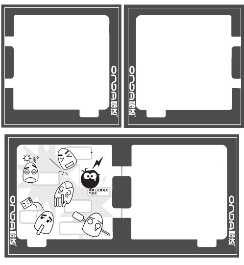
不要让任何物品 掉落在本机或 撞击本机请不要将播放器放置在温度过高、过低及潮湿的地方请不要接触化学物品 请不要撞击本机的LCD,切勿靠近带静电的物品,远离磁场切不可擅自拆卸、修理和改造注意事项03基本功能音乐模式 录音模式 语音模式电子书模式 系统设置 短按+/-键进入调节音量界面,+ 键音量加;- 键音量减。
FM收音2.短按MODE键进入播放子菜单。
3.拨动 键选择“音效模式”菜单项。
4.短按MODE键进入“音效模式”选择菜单5.拨动 +/- 键选择,短按MODE键确认6.各种音效说明(EQ): (自然效果,Natural) (摇滚效果,Rock) (流行效果,Pop) (古典效果,Classical) (柔和效果,Soft) (爵士效果,Jazz) (重低音,DBB)122.短按MODE键进入录音子菜单3.拨动 键,选择“录音类型”子菜单项4.短按MODE键进入录音类型选择界面5.拨动 选择合适的录音类型 6.短按MODE键确认选中的类型7.按Play键开始录音 优质录音,wav格式,音质好 长时录音,act格式,音质一般 优质声控,wav格式(声控录音,没有声音时会暂停录音) 长时声控,act格式2.拨动 键选择“语音模式。
3.短按MODE键进入语音模式界面。
录音模式语音模式PS:除了可以将ACT转换为WAV功能外,本工具还可以播放WAV和MP3格式文件。
2.选择要转换的ACT文件15FM收音(FM功能仅适用于VX818FM机型)1、进入主菜单。
电子书3.短按MODE键进入文本模式界面2.拨动 键选择“系统设置”。
键进入,选择所要看的文本文件,短按MODE键即3.短按MODE键进入“系统设置” 短按MODE键进入子菜单,选择”浏览间隔”,操作方法可参照”屏幕保护时间”设定。
注意:文本浏览只支持txt 和lrc 文件格式。
设定一个倒计时时间(秒),时间一到屏幕显示屏保2.拨动 键选择“背光时间”3.短按MODE键进入背光时间界面4.拨动 / 键调整时间5.调整完毕后按MODE键确定退出本韧件文件”按钮3.选择新的固件程序(可以在www.onda.cn上下载)本机可以识别用户在移动磁盘中建立的99个一级文件夹。
im818驱动使用手册

im818驱动使用手册
【原创实用版】
目录
1.介绍 im818 驱动
2.驱动的安装与使用
3.常见问题与解决方案
正文
一、介绍 im818 驱动
im818 驱动是一款由中国科技公司研发的手机驱动程序,适用于Android 操作系统。
它能够帮助用户更好地管理和操控手机设备,提供更为便捷的操作体验。
二、驱动的安装与使用
1.下载与安装
首先,用户需要在官方网站上下载适用于自己手机型号的 im818 驱动程序。
下载完成后,按照提示进行安装。
2.使用方法
安装完成后,用户可以通过以下步骤来使用 im818 驱动:
(1)打开驱动程序,选择“连接设备”;
(2)在弹出的窗口中,选择自己的手机型号;
(3)根据提示,允许或拒绝设备连接;
(4)连接成功后,用户可以通过驱动程序进行设备管理、文件传输等操作。
三、常见问题与解决方案
1.设备连接失败
如果遇到设备连接失败的情况,用户可以尝试以下几种解决方案:(1)检查手机和电脑是否连接在同一 Wi-Fi 下;
(2)检查手机和电脑是否在同一局域网内;
(3)尝试重启手机和电脑,然后再次连接。
2.文件传输失败
如果遇到文件传输失败的情况,用户可以尝试以下几种解决方案:(1)检查文件大小是否超过驱动程序的传输限制;
(2)尝试使用其他文件进行传输;
(3)检查手机和电脑的存储空间是否充足。
总之,im818 驱动是一款实用的手机驱动程序,能够为用户提供便捷的设备管理和文件传输功能。
研华PCL-818系列板卡中文手册
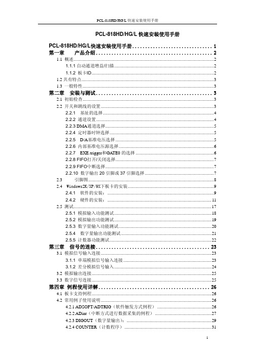
PCL-818HD/HG/L快速安装使用手册PCL-818HD/HG/L快速安装使用手册 (1)第一章产品介绍 (2)1.1 概述 (2)1.1.1自动通道增益/扫描 (2)1.1.2 板卡ID (2)1.2共有特点 (3)1.3 一般特性 (3)第二章 安装与测试 (3)2.1 初始检查 (3)2.2 开关和跳线的设置 (3)2.2.1 基址的选择 (4)2.2.2通道设置 (4)2.2.3 DMA通道选择 (5)2.2.4定时器时钟选择 (5)2.2.5 D/A基准电压选择 (5)2.2.6内部基准电压源选择 (6)2.2.7 EXE.trigger和GATE0的选择 (6)2.2.8 FIFO打开/关闭选择 (7)2.2.9 FIFO中断选择 (7)2.2.10 数字输出20引脚或37引脚选择 (7)2.3 引脚图 (8)2.4 Windows2K/XP/9X下板卡的安装 (9)2.4.1 软件的安装: (9)2.4.2硬件的安装: (11)2.5 测试 (17)2.5.1模拟输入功能测试 (18)2.5.2 模拟输出功能测试 (19)2.5.3 数字量输入功能测试 (20)2.5.4数字量输出功能测试 (21)2.5.5计数器功能测试 (22)第三章 信号的连接 (23)3.1 模拟信号输入连接 (23)3.1.1 单端模拟信号输入连接 (23)3.1.2 差分模拟信号输入 (24)3.2 模拟输出连接 (25)3.3 数字信号连接 (25)第四章 例程使用详解 (26)4.1 板卡支持例程 (26)4.2 常用例子使用说明 (26)4.2.1 ADSOFT/ADTRIG(软件触发方式例程) (26)4.2.2 ADint(中断方式进行数据采集的例程) (27)4.2.3 DIGOUT(数字量输出): (29)4.2.4 COUNTER(计数程序) (31)4.2.5 Digin (数字量输入例程) (31)4.2.6 PULSE(脉冲输出例程) (32)4.2.7 MADint(多通道中断采集例程) (33)4.2.8 ADDMA(DMA方式进行数据采集的例程)函数: (34)4.2.9 THERMO(热电偶数据采集) (36)第五章 遇到问题,如何解决? (37)第一章 产品介绍1.1 概述PCL-818L是PCL-818系列中的入门级板卡。
GT08 车载GPS追踪器用户手册说明书
GPS Vehicle Tracker USER MANUAL(Model:GT08)Version4.0(Date:Jan.7,2017)CONTENT Preface (2)I.Features&Functions (3)II.How to Operate it (4)Authorize the Alarm-received Phone No (4)Arm/Disarm by Phone Calling (4)Check the Vehicle’s Status (5)Arm/Disarm the System by SMS (5)Check the location by Google Map’s URL (5)Check the Real Physical Address (6)Check the Real Physical Address Directly without Server (6)Check the Location by GSM Base Station Code (6)Change User Password (6)Stop the Car by SMS (6)Restore Car from Being Stopped (7)Monitor the V oice around the Car (7)Two-way Talking (7)Over-speed Alert (7)Speed Limiter (8)Power Save Mode (8)Fatigue Driving Alarm (8)Show the SMS Content in Languages (9)Define the SMS Content in other languages (9)Other SMS Command List (10)III.The Setting for GPRS Connection (13)IV.Snap Photo&Monitor via MMS/Email/Platform (14)V.Alarm Types (16)VI.Installation (17)VII.Specifications (19)VIII.FAQs&Troubleshooting (19)IX.Maintenance (20)PrefaceGT08GPS Vehicle tracker is the most advanced&cost-effective solution for vehicle security,real-time tracking&fleet management.It has the following unique functions:✧Support wireless immobilizer;✧Fuel leaking alarm,speed limiter&fatigue driving alarm;✧It is integration with GPS tracker+Car alarmRead it Firstly:Please read this manual thoroughly before you use the device;please keep it for future reference.Attention:(1)Please keep the device away from heavy water,high temperature,heavy dust or strong magnetism.(2)Please prepare a valid GSM SIM card in advance.(3)For safety,please keep the SIM number of your tracker in secretWarning:We strongly suggest user let the professional car electrician to install the system.I.Features&Functions1.Industrial design with high performance ARM7process2.Track on command or by time interval or by distance;3.Arm/disarm by SMS,phone call;4.Check the car’s real physical address(such as city name,street name..);5.Track by mobile SMS to get the latitude,longitude,speed,direction&odometer etc.6.Check the location directly by the Google map’s URL;7.Over-speed alert,Geo-fence alert,movement alarm;8.Snap photo and send out via MMS&Email when there is SOS alarm,ACCOn alarm or door open alarm,snap the photo via platform(optional);9.Speed limiter,when the speed is over limitation,the siren will sound to warndriver&relay will response to slow down the car automatically;10.Crash alarm,when there is crash&it can detect it automatically;(optional)11.Fatigue driving alarm,if continuous driving time is over the limitation,thealert will be triggered;12.Check the coordinates via LBS,even there is no any GPS signal..13.Support voice monitoring&2-way talking;14.Cut off engine to stop the car safely by SMS/GPRS;15.Trace optimization when vehicles turns a corner;16.Built-in shock sensor for power saving&triggering alarm17.Power failure alarm,with built-in rechargeable backup battery;18.SOS alarm(optional);19.Support analog input for fuel/temperature monitoring,fuel loss alarm;20.I/O:4digital inputs,1analog inputs&1digital outputs;21.There are3types of working mode for power saving flexibly.22.8M-bit offline data logger,it can store up to9,090waypoints.23.SMS content in multi-languages(English,Arabic,Spanish,Portuguese).II.How to Operate itThe default user password is111111.If the user password is changed,user should send the SMS command withXXX is the control code,all the letters must be capital letters or in small letters,command with mixed capital letter&small letter is not recognized by systemAuthorize the Alarm-received Phone No.SMS command:111111*10Mobile#1*20Mobile#2*In case of alarm,if user wants to get the alarm SMS from the tracker,he/she needs send the following SMS to program the tracker firstly,otherwise,the alert information can't be received correctly.Example:User sends the SMS111111*1013922713571*2013711189059*to the tracker’s SIM card number,if there is any alarm,system will send SMS to both of these two mobiles.In case of SOS alarm,the system will only send alarm to the mobile#2Arm/Disarm by Phone CallingUser could also use the1st alarm-received mobile phone to call the tracker’s SIM card number,so as to arm/disarm the system.Arm:After hearing several ring tones,if the systems hang up the call automatically,and call back you,it means that the system is armed.Disarm:After hearing several ring tones,if the system hangs up the call automatically,and don’t call back you,it means that the system is disarmed.Note:(1)There is no communication fee for this operation,it is a very convenient way to arm&disarm the system.(2)The SIM card inside the device must have the function of Caller ID Display.(3)Only the1st alarm-received mobile phone can realize this function.Check the Vehicle’s StatusSMS command:111111CHK(or111111chk)This instruction is used to inquiry the vehicle’s location&system’s status.The system will send back the SMS,includes the similar information,such as“Armed……”User could also use the2nd alarm-received mobile phone to call the tracker’s SIM card number,the tracker will hand up the calling&send back the location directly.Arm/Disarm the System by SMSSMS command:111111ARM(or111111arm)This SMS instruction is used to arm the systemSMS command:111111DSM(or111111dsm)This command is used to disarm the system&stop sending alert SMS.Check the location by Google Map’s URLSMS command:111111MAP(or111111map)Upon receiving the SMS command,the tracker will automatically send back the SMS including the Google map’s URL,user can use smart phone(GPRS data service is enabled)to open the URL link,the car’s location will be showed on the Google map.Check the Real Physical AddressSMS command:111111ADD(or111111add)When user sends this SMS command to the tracker,the tracker will automatically send back the car’s real physical address(such as city name,street name)to your mobile by SMS.(it need server's support for address translation).Check the Real Physical Address Directly without ServerSMS command:111111DDD(or111111ddd)When user sends this SMS command to the tracker,the tracker will automatically send back the car’s real physical address(such as city name,street name)to your mobile by SMS.(Note:this function might not work with some operator's SIM card.it is just for test).Check the Location by GSM Base Station CodeSMS command:111111LOC(or111111loc)This instruction is used to check the location by GSM base station code. The tracker will send back the relative GPS coordinates which is translated by the GSM base station code.Change User PasswordSMS command:111111PSWnnnnnn(or111111pswnnnnnn)This instruction is used to change the user password.The length of the user’s password is3~ers are suggested to change to the new password in use.Example:User sends the SMS“111111PSW12345”to the system SIM card number,and gets the confirmed SMS“111111PSW12345”in3seconds.It means that the user password has been changed to12345.Remark:Please keep the password deep in mind if it is changed.Stop the Car by SMSSMS command:111111STP(or111111stp)This instruction is used to stop the car in safe condition.If the car's speed is higher than30KM/h,the car is stopped gradually by impulse control,if the car's speed is lower than30Km/h,the car is stopped immediately.Attention:It is very dangerous to stop the car when the vehicle is running at high speed.We do not take any responsibility to the consequence caused by this action.Restore Car from Being StoppedSMS command:111111RES(or111111res)It is used to restore the car to normal status after being stopped.Monitor the Voice around the CarSMS command:111111MONThis instruction is used to monitor the voice around the car.The SIM card inside the system pays for the communication fee.SMS command:111111MON!This instruction is used to monitor the voice around the car.The user’s telephone pays for the communication fee.Example:User uses the mobile137****2345to send111111MON!to the system, then use the mobile137****2345to call the tracker,it will be connected automatically,and user can monitor the voice around.Two-way TalkingSMS command:111111MON:P1*This instruction is used to program the phone number which is used for carrying out direct monitoring or talking always.P1is suggested as center phone number for easy communication with drivers.Example:111111MON:139****3571*Over-speed Alert111111SPD:X x is the speed in KM/H,maximum value is255M/H(For example:111111SPD:120,if the car speed is over120KM/H,it will send out warning alert by SMS/platform).111111SPD:0to disable the over-speed alert.It is the default setting.111111SPD:to check the setting of over-speed alert.Remark:this function is just for reference,because there might be some time delay or error in detecting the running car’s real speed by GPS.Default speed limitation is120KM/H.Speed LimiterAfter user sets the speed limitation by command111111SPD:X,if car is over speed,the car will be slowed down gradually.111111BUZ:3:X,(X=1,activate siren;X=0:deactivate siren;default=1)111111RLY:3:X,(X=1,activate relay;X=0:deactivate relay;default=1)Power Save ModeSMS command:111111PWR:XValue of X Actions Power consumption 0(default)Disable power save mode60mA 1Close GPRS connection48mA2Close GPRS connection,GPS module13mA After setting111111PWR:1(or2),if there is no vibration&SOS alarm, integration line is not triggered,and ACC is OFF,the tracker will go into power save mode after5minutes.Once there is vibration or SOS alarm,or integration line is triggered,or ACC is ON,the tracker will wake up from the power save mode immediately.Fatigue Driving AlarmWhen this function is activated,if the engine is turned on for a certain time, the siren will sound to warn the driver.The SMS command:111111TIR:1:X,(with,at the end)X:is time in minutes(default:X=180minutes,maximum:65535minutes) Example:111111TIR:1:120,Show the SMS Content in Languages.SMS command:111111LNG:Xit is used to define the SMS content in different languages.X=0,English;X=1,Chinese;X=2,Arabic;X=3,Portuguese;X=4,Spanish;(Default setting:X=0,English) Define the SMS Content in other languagesStep1:choose the language mode such as:111111LNG:4to change to Spanish language firstly.Step2:Define your own text by the following command:111111TXT:nn:str!nn:str!nn:str!nn:str!nn:str!nn:str!Remarks:(1)6pieces of strings can be defined in one command.(2)nn:2bits,range:01~18(3)the number of letters in each str.can't be more than8(4)the character(.),(.),(!)can't be showed in str.Example:111111TXT:09:vibración!is to define the alarm text in Spanish when the shock sensor is triggerednn Meaning of Str.01Arm02Disarm03Power failure alert04SOS alert(in1)05Engine ON alert(in4)06Vibration alert07Stop the car(out1)08Restore the car(out1)09Over-speed alert10Original alarm's triggering(in5)11Geo-fence alert12Movement alert13The vehicle can't be stopped14Crash alert15Car door open alert(in3)16Broken line alert(in2)17Fuel loss alert18Un-defineOther SMS Command ListNote:******is user’s password and the default password is111111.The tracker will only accept commands with the correct password.III.The Setting for GPRS ConnectionThe GPRS setting is necessary for using the following2functions:(1)Check the car’s real physical address by send111111ADD(2)Online tracking service by web-based tracking platformSMS format:111111WWW:IPN:X;COM:X;APN:apn,user,password;RPT:X;SLP:X;RUN:X;⏹IDN:The tracker’s ID,it is the last14digits of IMEI which can't bechanged.⏹IPN:The IP address or domain name of the GPRS server⏹COM:The communication port for the GPRS server⏹APN:The Access Point Name for the GSM SIM card.⏹RPT:The interval for the uploading GPRS packet(Unit:sec.)⏹SLP:The interval for uploading GPRS packet when car is parked(Engine is OFF and no vibration).(unit:sec.);⏹RUN:GPRS connection setting.0=close,1=TCP,2=UDP.⏹IDN:The tracker’s ID,it is the last14digits of IMEI which can't bechanged.Example,if server is:,TCP port is8500,APN is web.gprs,,apn user:web,apn password:web,time interval is60 seconds,Then the command is:111111WWW:IPN:;COM:8500;APN:, web,web;RPT:60;RUN:1;User can send one or more options at the same SMS commands,such as:✧111111WWW:IPN:X;COM:X;This is to set the server’s address and port separately.Example:111111WWW:IPN:;COM:8500;✧111111WWW:APN:X;This is to set the APN(access point name).Please use“,”to separate the APN,APN username&APN password.Example:111111WWW:APN:,web,web;✧111111WWW:RPT:X;This is to set the upload time interval.The unit is second,the minimum value is10seconds.The default setting is60Example:111111WWW:RPT:60;(Upload time interval is every60s)✧111111WWW:RUN:X;X=0;is to close down the GPRS;X=1;is to open the GPRS via TCPX=2;is to open the GPRS via UDPEg:111111WWW:RUN:1;(Open the TCP connection)✧111111WWW:You can send111111WWW:to check the GPRS settings.Default GPRS SettingThe default GPRS setting is:✧IPN:,COM:8500✧APN:cmnet RPT:30seconds✧SLP:0RUN:1IV.Snap Photo&Monitor via MMS/Email/Platform It is the optional function for3G version,the extra serial camera is needed.✧Snap the Photo via MMS111111MMS:to get the Photo via MMSTo realize this function,user must do the correct MMS settings firstly.✧MMS Setting for SnappingThe MMS setting is different from GPRS setting,the SMS command is as following:✧X:MMSC server URL;✧Y:The IP of MMS proxy✧Z:MMS_APN,user,Password.✧N:The Port of MMS proxyFor more information about the MMS settingparameters of worldwide GSM operators,please searchby Google or refer to this link:/mobile-operator.mmsc-settingsExample:(for Nigeria MTN SIM card)The correct setting SMS command is:111111MMS:SVR:http://10.199.212.8/servlets/mms;PRX:10.199.212.2;APN:web.g,web,web;COM:8080;✧Set the Way of Sending PhotoSMS command:111111PIC:1:X,2:X,3:X,4:X,5:X,6:X,7:X,8:X,9:X,(with,at the end)X=0,means Disable;X=1,means Enable1:X,engine on(input4);2:X,car door open(input3);3:X,over-speed;4:X, vibration;5:X,movement alarm;6:X,fatigue driving alarm;7:X,broken line alarm(Input2);8:X;original alarm's triggering(input5);9:X;SOS(Example:111111pic:1:1,2:1,9:1,)default setting as1.SMS command:111111SEE:6:X,7:Y,8:Z,(with,at the end)6:X,X=1,send photo via MMS to1st alarm-received no.;X=0,disable.7:Y,Y=1,send photo via MMS to2nd alarm-received no;Y=0,disable.8:Z,Z=1,send photo to email box;Z=0,disable.(Example:111111SEE:6:1,7:1:8:1,)✧Set the Email to Receive the PhotoSMS command:111111BOX:Email(Example:111111BOX:*******************)V.Alarm TypesVibration AlarmIn arming status,if the car is vibrated,it will send out alarm SMS.Power Failure AlarmIn arming status,if the battery is cut off,it will send out alarm SMS.Engine ON AlarmIn arming status,if the car’s engine is ON,it will send out alarm SMS and call the preset phone.Movement AlarmIn arming status,the movement alert is enabled automatically.Once the car moves away from the parking point for100meters,it will it will send out alarm SMS and call the preset phone.Geo-Fence AlarmOnce the Geo-fence is activated,if the car oversteps the boundary,it will send out alarm SMS.Over-speed AlarmIf the car runs over the speed limitation continuously for3minutes,it will send out alarm SMS.SOS AlarmIn any condition,if the SOS button is pressed,it will trigger the SOS alarm.(NOTE:the SOS alarm will only be sent to the2nd phone,the3rd phone number&the GPRS tracking center,the other alarms will send to all the preset phones&GPRS tracking center.)Crash Alarm(optional)If there is crash,the crash sensor will detect it and send out alarm.Fatigue AlarmIf the accumulated time of engine on is over the setting,the sire will sound to warn the driver.Fuel loss Alarm(optional)When the engine is OFF,if the fuel level is down,it will trigger the alarm.VI.InstallationInstallation Steps:(1)Please read the manual carefully before installation.Please prepare a validGSM SIM card with Caller ID Display&GPRS function;(2)Please push the front cover according to the direction;(3)Insert the valid GSM SIM card,then turn on the backup battery switch;(4)Close the cover,and fix the main unit tightly with the wiring harness at thecorrect place,please make sure that the side with GPS antenna is placed upside to sky,please make sure to install the main unit at broad place so that it can receive GPS signal well.For motorcycle,it is better to install inside the head bulb light where there is power supply and water proof.For vehicle,it is better to install inside the upper rim of the driving room or inside the dashboard.The recommend installation place is showed in the following picture:For motorcycle For vehicle(5)Do the wring connection according to the diagram;(6)Call the SIM card,to check if rings,if not,then check the power supply andthe change the place of installation;(7)If it rings when calling the SIM card,then send SMS to the tracker to checkthe GPS coordinate,if the GPS location is not correct,then fix the main unit to other place so that it can receive better GPS signal.(8)IMPORTANT:The side with GPSantenna must be placed upside to thesky and kept away from the metalmaterials,otherwise,it can’t get GPSsignal well.VII.SpecificationsVIII.FAQs&Troubleshooting(2)Low power,please use outside power supply to power on the unit to testI can not get the alarm message (1)The SIM card inside the device has no credit;(2)The Alert-received mobile number is not programmed correctly,or the SMS command is not in correct format;(3)The mailbox of the user’s mobile is full;I can not get the correct GPS coordinates or the location is wrong (1)Please make sure there is no metal obstacles above the tracker.Please place the side with GPS antenna upside to the sky;(2)Please check it at broad place;(3)Please check if the GPS LED flash once every3seconds;place the tracker to other place, so as to make sure that it can receive the GPS siganl well(4)In cloudy condition,it is a little hard to get the GPS signal,and the GPS coordinate might have some errors.Tracker fails to connect to server by GPRS (1)The SIM card must be activated with GPRSfunction;(2)Do the correct setting for GPRS connectionIX.Maintenance✧The installation must be done by the professionals.Illegal disassemblywithout permission might cause invalidity of warranty.✧Please keep the device in dry place✧When the car is inside buildings,cave,tunnel,or very close to tall buildings,the GPS/GSM signal may not work well and the system may fail to work at that moment.✧Please check the balance of the tracker’s SIM card periodically.✧The backup battery can only work for a certain time once power-off.FCC Information and CopyrightThis equipment has been tested and found to comply with the limits for a Class B digital device, pursuant to part15of the FCC Rules.These limits are designed to provide reasonable protection against harmful interference in a residential installation.This equipment generates,uses and can radiate radio frequency energy and,if not installed and used in accordance with the instructions,may cause harmful interferenceto radio communications.However,there is no guarantee that interference will not occur in a particular installation.If this equipment doescause harmful interference to radio or television reception,which can be determined by turning the equipment off and on,the user isencouraged to try to correct the interference by one or more of the following measures:—Reorient or relocate the receiving antenna.—Increase the separation between the equipment and receiver.—Connect the equipment into an outlet on a circuit different from that to which the receiver is connected.—Consult the dealer or an experienced radio/TV technician for help.This device complies with part 15 of the FCC Rules. Operation is subject to the condition that this device does not cause harmful interferencechanges or modifications not expressly approved by the party responsible for compliance could void the user's authority to operate the equipment.This equipment complies with FCC radiation exposure limits set forth for an uncontrolled environment.This equipment should be installed and operated with minimum distance20cm between the radiator&your body.This transmitter must not be co-located or operating in conjunction with any other antenna or transmitter.。
im818驱动使用手册

im818驱动使用手册摘要:一、前言二、im818 驱动概述1.im818 驱动的定义2.im818 驱动的功能三、im818 驱动安装与配置1.安装前的准备2.安装步骤3.配置说明四、im818 驱动使用方法1.设备连接2.驱动程序启动3.主要功能模块五、im818 驱动常见问题及解决方法1.驱动安装问题2.驱动使用问题3.设备连接问题六、im818 驱动的维护与升级1.驱动维护方法2.驱动升级流程七、总结正文:【前言】im818 驱动使用手册旨在帮助用户了解im818 驱动的安装、配置和使用方法,以及解决驱动使用过程中可能遇到的问题。
本手册适用于使用im818 驱动的各类设备,包括计算机、服务器等。
【im818 驱动概述】im818 驱动是一款针对计算机硬件设备开发的驱动程序,主要负责实现计算机与硬件设备之间的数据传输和控制信号。
im818 驱动支持多种硬件设备,具有广泛的兼容性,可满足不同用户的需求。
【im818 驱动安装与配置】【安装前的准备】在安装im818 驱动前,请确保计算机已安装操作系统,并准备好im818 驱动程序文件。
同时,请确保硬件设备已连接到计算机上。
【安装步骤】1.下载im818 驱动程序文件,并将其保存在一个易于访问的位置。
2.打开计算机的设备管理器,查看是否有未知设备。
如果有未知设备,请先卸载该设备。
3.解压下载的im818 驱动程序文件,然后双击运行安装程序。
4.按照安装向导的提示完成驱动安装过程。
【配置说明】安装完成后,可能需要对im818 驱动进行一些配置。
具体配置方法请参考设备说明书或联系设备厂商。
【im818 驱动使用方法】【设备连接】将硬件设备连接到计算机上,然后打开设备管理器查看设备是否已成功识别。
【驱动程序启动】双击设备管理器中的im818 驱动程序,启动驱动。
【主要功能模块】im818 驱动的主要功能模块包括数据传输、设备控制和故障检测等。
具体功能请参考设备说明书或联系设备厂商。
ANDROID Platform GT818 驱动移植说明书
Android平台GT818驱动移植说明书【程序总揽】本程序针对Android2.1系统,移植的硬件平台为华天正科技开发的Real6410(基于S3C6410)。
本驱动支持多指,能够在系统支持的情况下在主控进入关屏状态时自动调整GT818工作状态,达到省电的目的。
1.1系统资源使用1.2系统运行流程为了便于移植,程序中采用了中断和定时查询两种方式,并建议使用中断方式。
以中断方式为例,系统的主运行流程如下所示:1.创建Guitar对应的i2c_client对象,其中完成了该适配器的相关信息设置;2.加载触摸屏驱动,注意该驱动必须在I2C总线驱动已经加载的情况下才能进行,否则I2C通信将出错。
程序中将其加载优先级设为最低;3.创建驱动结构体,探测Guitar设备,并将其挂载到I2C总线驱动上;测试I2C通信,注册input设备,申请IO口和中断资源,完成Guitar初始化工作(如有需要,烧录升级在此进行);4.开启触摸屏中断,等待数据接收;5.收到触摸屏数据中断,关中断;6.通过I2C传输数据,分析手指信息,;7.更新按键信息,上报手指坐标、按键等信息,开中断;8.重复4-7之间的循环。
【移植指南】4.准备工作本驱动采用GPL许可证,代码没有采用模块方式,所以使用本驱动前需要重新编译内核。
在编译内核前,我们需要做好以下准备工作:1、在硬盘上或使用虚拟机(如VmWare)安装Linux系统,推荐使用Ubuntu9.10;2、安装gcc及arm-linux-gcc和其他编译工具,将CC和LD指定为arm-linux-gcc;3、获取平台对应的Android源码,解压到自己的工作目录。
4、了解移植平台的IO口、中断、I2C总线的使用方式。
5.内核编译配置在编译代码前我们需要进行内核编译配置,可以使用下面命令中的一个:#make xconfig (基于QT的图形配置界面,非常直观,推荐使用)#make menuconfig (基于文本菜单的配置界面)下面我们以make xconfig为例,将我们的驱动增加到内核中去。
移植android驱动遇到的一些问题和解决
移植android驱动遇到的一些问题和解决郑重声明:(可能有些不是能解决,还请见谅)1、Q:apt-get: command not foundA:先搞清楚自己用的是啥系统吧,如果是ubuntu或者d ebian,去相应的版块问问题,否则,改用yum,Fed ora里面找不到apt-get不是什么太奇怪的事情。
在Fed ora里正确的安装procinfo的方法就是(首先确保你是超级用户),yum install procinfo。
你使用的su -c 'yum install procinfo'是正确的,如果装不上,就把错误信息贴出来。
2、Q:nandflash如何正确分区:A:(1)MISC分区其中misc分区信息第一篇文章有解释: 保存设备配置信息:CID (Carrier or Region ID),USB和其它硬件设备配置信息,大约20K的样子。
(2)recovery分区recovery 分区即恢复分区,在正常分区被破坏后,仍可以进入这一分区进行备份和恢复.我的理解是这个分区保存一个简单的OS或底层软件,在Android的内核被破坏后可以用bootl oad er从这个分区引导进行操作。
(3)boot 分区一般的嵌入式Linux的设备中.bootload er,内核,根文件系统被分为三个不同分区。
在Android做得比较复杂,从这个分区和来看,这里boot分区是把内核和ramdisk fil e的根文件系统打包在一起了,是编译生成boot.img来烧录的。
它有如下格式。
(4)rootfs-combin分区:文件系统分区(5)cache分区:缓存(6)一个分区例子[ 2.329249] 0x0000000c0000-0x000000100000 : "misc"[ 2.337472] 0x000000100000-0x000000900000 : "recovery"[ 2.343285] 0x000000900000-0x000000c00000 : "kernel"[ 2.347297] 0x000000c00000-0x00000cc00000 : "rootfs-combin"[ 2.384980] 0x00000cc00000-0x000010000000 : "cache"3、Q:想把自己写的一个flash的驱动程式加载到工程中,而且能够通过menuconfig配置内核时选择该驱动该怎么办呢?A:第一:将您写的nandflash_tast.c 文档添加到/driver/mtd/maps/ 目录下。
多普达818说明书

認識您的818Dopod 818軟體光碟雙耳耳機充電器USB連接線使用手冊快速使用指南電池皮套認識您的設備1. 插入SIM卡3. 撥打電話打開您的電話按下電源鍵即可打開您的818. 設定的歡迎畫面將會出現. 請依照系統的指示,同時利用觸控筆去校正您的螢幕.在撥號畫面時輸入PIN碼然後按下輸入即可開機.撥打電話最直接的方法是使用電話按鍵。
1.按 鍵叫出撥號器畫面。
2.點選鍵盤的數字,然後點選 或按下鍵即可撥出電話。
從連絡人撥打電話您可以利用下列方式,從連絡人中撥打電話。
⏹按下位於 Dopod 818 左上角的Microsoft連絡人按鍵。
⏹找到您要撥出的連絡人,然後按兩次 鍵(按第一次將號碼送到撥號畫面,第二次則開始撥號)。
⏹點選撥號畫面下方的 ,如此可開啟Microsoft連絡人畫面。
從連絡人清單中選擇一個對象,然後按兩次 鍵。
按下鍵的預設顯示為公司電話。
不過您也可以自訂顯示行動電話號碼或電子郵件來取代。
⏹在連絡人清單中,點選您要自訂的連絡人右欄中的w。
快顯功能表會列出這個連絡人的電話號碼及電子郵件信箱,而優先顯示的號碼旁邊則會標示一個圓點記號。
⏹按壓方向鍵的往左或往右鍵,則畫面上的號碼顯示會改變,依序輪流顯示m(行動電話)、w (公司電話)或E (電子郵件信箱)。
人資訊您的Dopod 818 可以使用下列的方法充電:1.將您的Dopod 818 插在同步傳輸基座上並用AC變壓器連接上外接電源。
第一次充電時,請持續充電至少8小時,然後每天將本機置於傳輸基座中一段時間,讓您的Dopod 818 隨時充滿電量。
2.將AC變壓器連接到選購的USB傳輸線,讓您的Dopod 818 直接連接到外接電源。
如果您的818是關機狀態,充電的時候LED會顯示橘色.如果在開機狀態時,充電時會顯示深琥珀色,同時螢幕上會有充電的指示.充電完成後LED會顯示淡綠色,螢幕上也會顯示充電完成的訊號.您可使用USB連接線或充電器來加以充電.備份您的資料:出現電源不足警告訊息時,請立刻儲存您正在處理的資料、並與電腦執行同步化作業,再將Dopod 818 的電源關閉。
GT9XX驱动移植说明书_for_Android_2014011401
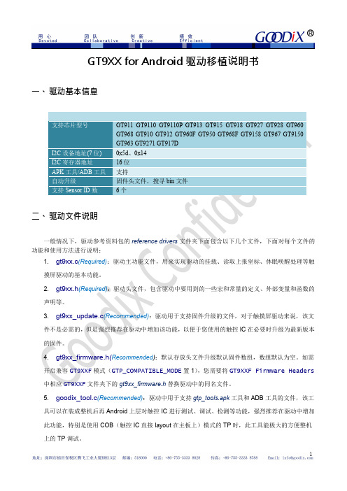
3. gt9xx_update.c(Recommended):驱动用于支持固件升级的文件,对于触摸屏驱动来说,该文
件不是必需的,但是强烈推荐在驱动中增加该功能,以便于您使用的触控 IC 在必要时升级为最新版本 的固件。
4. gt9xx_firmware.h(Recommended):默认存放头文件升级默认固件数组,数组默认为空。如需
开启兼容 GT9XXF 模式(GTP_COMPATIBLE_MODE 置 1),您需要将 GT9XXF Firmware Headers 中相应 GT9XXF 文件夹下的 gt9xx_firmware.h 替换驱动中的同名文件。
5. goodix_tool.c(Recommended):驱动中用于支持 gtp_tools.apk 工具和 ADB 工具的文件,该工
obj-y += gt9xx.o gt9xx_update.o goodix_tool.o
3. 添加设备:找到 kernel 中初始化 I2C 总线的板级文件,如本驱动的开发平台 real6410 开发板是位 于 arch/arm/mach-s3c6410/ mach-smdk6410.c 文件中,如需要将触摸屏驱动挂载 I2C0 总线上,则按 以下方法添加 TP 的 i2c 设备驱动即可,0x5d 为该型号触控 IC 的 i2c 从设备地址,具体为多少需参阅 该型号芯片的 datasheet,”Goodx-TS”为 i2c 设备驱动名,必须与驱动参考代码中的 GTP_I2C_NAME 保持相同。
static struct i2c_board_info i2c_devs0[] __initdata = {
{ I2C_BOARD_INFO("Goodix-TS", 0x5d),}, };
818详细图片刷机教程

818详细图片刷机教程准备:<?xml:namespace prefix = o ns = "urn:schemas-microsoft-com:office:office" />硬件:1. 读卡器2. SD或MMC卡,容量在 <?xml:namespace prefix = st1 ns ="urn:schemas-microsoft-com:office:smarttags" />128M或128M以上都可以,推荐128M .3. USB连接线,买机有原配的.软件:1. romupdate.exe -用来把机器原版ROM写到SD/MMC卡上.程序要放在C:盘下才可以!2. ntrw.exe -用来把SD/MMC卡上的原版ROM读取到电脑里,再将修改文件头(后文会教怎么改)后的ROM写到SD/MMC里去.程序要放在C:盘下才可以!3. HHD Hex Editor -用来修改ROM文件头.4. ROM 文件 , 有很多 , 你要刷什么就下载什么 !开始刷机 :1. 读取原版 ROM首先将 Microsoft ActiveSync 连接设置中的” 允许 USB 连接” 选项去除 , 如图 ! 去除后 , 在系统托盘区的同步图标会打个小红叉 , 代表成功 !2. 然后将机器切换到启动模式 , 方法是同时按住相机和电源按钮 , 然后用笔按热启孔 , 我的启动版本是 V1.02, 连上 USB 线 , 此时屏幕上会显示”USB”, 代表何 PC 连接成功 , 下一步是将原版 ROM 读取到SD/MMC 卡上 !3. 将 128M 的 SD/MMC 卡插入机器 , 打开 romupdate.exe, 然后选择 USB 接口 , 其他选项默认 ! 如果没有类似于图中的接口 , 那请检查你的操作步骤 , 并重新开始 ! 如图 !4. 点击确定后出现如图窗口 , 在窗口中输入”d2s” 后回车 ! 开始读取原版 ROM 到 SD/MMC 卡上 ! 此时机器屏幕上显示”Storing… X%”, 其中的数字是读取进度 ! 这个过程大概需要 3-5 分钟 ! 请耐心等待 ! 结束后机器屏幕会显示”CheckSum is OK!”,PC 软件会显示如图信息 !然后拔下 USB 线 , 取出 SD/MMC 卡 ! 下面进行读取 ROM 到 PC, 修改 ROM 的过程 !5. 将 SD/MMC 卡插入读卡器 , 此时可能会提示是否格式化存储卡的提示 , 选否 , 不然读出来的 ROM 就没了 ! 然后运行 ntrw.exe, 点开始 -> 运行->cmd->cd\, 然后输入”ntrw read OriginalRom.nb1 X:” 其中OriginalRom.nb1 是 ROM 保存后的名字 , 可以自己随意输名字 !X: 是你读卡器的盘符 ! 读出的 ROM 在 C 盘根目录下 ! 如图 !6. 在 C 盘下找到读出的 ROM 文件 , 备份一下 , 防止修改失败后又要重新读取 ROM, 下面开始修改需要刷新的 ROM 的文件头 !假设你要刷新的 ROM 文件名字为 bsrom, 你备份出来的 ROM 文件名为 Test. 打开 HHD Hex Editor, 点 File->Open-> 选择名字为 Test 的 ROM 文件 , 选择前 416 个字节 , 复制下来 , 关闭这个 ROM 如图 !再打开名字为 bsrom 的 ROM 文件 , 从 0 字节开始 , 将复制的内容粘贴过去 , 会自动覆盖 bsrom 的前 416 字节 , 然后被覆盖的部分会变成红色 , 然后保存如图 ! 这个过程完毕 , 下面开始将修改的 ROM 写入 SD/MMC 卡进行刷机 !7. 将 SD/MMC 卡插入读卡器 , 将修改后的 bsrom 放到 C 盘根目录下 , 也就是同 ntrw.exe 在同一目录下 , 然后按照读 ROM 的操作进行 , 点开始 -> 运行 ->cmd->cd\, 然后输入”ntrw write bsrom.nb1 X:” 其中 X: 是你读卡器的盘符 ! 如图 !结束后 , 修改的 ROM 就写入到 SD/MMC 卡里了 , 下面准备刷机 !8. 将写好ROM 的SD/MMC 插入机器, 此时机器会提示是否格式化存储卡, 依然选否, 原因你知道了! 然后将机器切换到启动模式, 相机键+ 电源键+ 软启 ., 画面开始显示”Serial”,10 秒后显示”SD Download Section=1 Press Power to Flash……”, 然后按下电源键开始刷新, 下面有进度百分比, 在刷新完毕后会提示两个Faild, 不要管,。
android自定义驱动(第一篇驱动)

android自定义驱动(第一篇驱动)简介功能总体自下而上的流程如下:•1、kernel层驱动实现,提供设备驱动节点文件•2、user层Hal抽象硬件接口定义和实现•3、HDIL接口定义,实现Binder服务端,提供给Framework层调用•4、Framework层JNI作为Binder客户端调用HDIL 接口,并提供AIDL接口应用层使用•5、App应用层通过调用AIDL调用Framework提供的服务案例环境如下:•手机设备:Nexus 6p•开发环境系统:Ubuntu14•开发环境:AOSP内核 Linux 3.10.73•Android源码版本:8.1一、创建驱动项目在内核源码目录/drivers/下,新建hello目录:msm/drivers$ mkdir hellomsm是我内核源码目录二、目录下创建hello.h文件源码地址:#ifndef _HELLO_ANDROID_H_ #define _HELLO_ANDROID_H_ #include<linux/cdev.h> #include<linux/semaphore.h> #define HELLO_DEVICE_NODE_NAME "hello" #d efine HELLO_DEVICE_FILE_NAME "hello" #define HELLO_DEVICE_PROC_NAME "hell o" #define HELLO_DEVICE_CLASS_NAME "hello" struct hello_android_dev{ int val; // 代表寄存器,类型为int struct semaphore sem; // 信号量,用于同步操作 st ruct cdev dev; // 内嵌的字符设备,这个Linux驱动程序自定义字符设备结构体的标准方法 }; #endif这个头文件定义了一些字符串常量宏,后面会使用到。
GT818编程指南

GT818编程指南文件一、接口说明a) GT818与主机接口共有6 PIN,分别为:VDD、GND、SCL、SDA、INT、RESET。
其中VDD、GND、SCL、SDA、RESET五个PIN脚为必需。
INT依赖于功能不同,可进行如下选择:主控的INT 口线需具有上升沿或下降沿中断触发功能。
并且,当其设置在输入态时,需取消其内部的上拉和下拉功能,保持在悬浮态。
主机可通过输出低和输入态(或OD)来控制GT818的RESET口为低或为高。
因为GT818被唤醒时RESET脚会有一段时间输出低,主控若是用输出高代替上拉高容易造成造成短时间大电流。
GT818与主机通信采用标准I2C通信,最高速率可以支持至600K bps。
当主机采用200K以上的通信速率时,需要特别注意I2C口的外部上拉电阻阻值,以保证SCL、SDA边沿足够陡峭。
b) GT818在通信中始终作为从设备,其I2C设备地址由7位设备地址加1位读写控制位组成,高7位为地址,bit 0为读写控制位。
GT818有三个从设备地址可供选择,如下表:如主机未对GT818重设I2C地址,其默认I2C从设备地址为0xBA和0xBB,I2C地址重设方法请参考第八节。
二、通信时序a) 主机对GT818进行写操作采取如下时序:……S:起始信号。
Address_W:带写控制位的从设备地址。
ACK:应答信号。
Register_H、Register_L:待写入的16位寄存器首地址。
Data_1至Data_n:数据字节1-n。
E:停止信号。
设定了写操作寄存器首地址后,可以只写一字节数据,也可以一次性写入多个字节数据,GT818自动将其往高地址顺序存储。
b) 主机对GT818进行读操作采取如下时序:先通过前述写操作时序设定待读取寄存器首地址,再重新发送起始信号进行读寻址,读取寄存器数据。
Address_R:带读控制位的从设备地址。
NACK:最后一字节读完主控回NACK。
设定了读操作寄存器地址后,主控可以一次读取一字节,也可以一次性读取多个字节数据,GT818自动递增寄存器地址,将后续数据顺序发送。
G810详细刷机教程

G810刷机教程-by xlus(以下内容机友xlus/xluschen原创,转载的朋友请注明出处)俗话说:工欲善其事,必先利其器。
刷机前我们应该做好充分准备工作,多看教程,这样才能最大程度上保证爱机不变砖。
1、通过Samsung PC Studio 7备份好所有用户数据(注意在备份设置里要选“手机存储”才能备份联系人)。
2、将810的电池充满(刷机时间不长,但为安全起见,还是建议满电操作)。
3、准备好刷机所需的所有软件,包含:G818E_SS60_Downloader_Driver 驱动程序(内含PHONE_driver和PDA_driver二个文件夹)G818_Apollo v4.32A FOR China 刷机工具G810 ROM文件即刷机包(有二个文件,拿F2版来说:一个是G810DZHF2_AP.IMG,一个是G810DZHF2_CP.bin,少任何一个文件请不要刷!)一切准备就绪,啥也不说了,开刷吧?等等,别急,请花一两分钟读耐心阅读以下注意事项:1、刷机过程中请注意手机和电脑均不能断电,有条件的建议用笔记本满电操作;2、刷机中每次连接电脑时,先用数据线连好手机,然后再连电脑,断开连接时,断开电脑端即可;3、刷机过程中810蓝屏状态下无法通过开机按钮关机,请直接取下电池关机。
4、刷机全过程请不要运行任何Samsung PC Studio软件,避免出现问题。
5、二个刷机驱动有任何一个安装不成功,请不要刷机!切记,否则可能成砖头,刷机有风险!6、第二次刷机时,如果用的不是上一次刷机的USB口一定要重新安装驱动,切记!!7、若上述两个驱动中任何一个驱动安装完成后提示重启电脑的话,按提示重启;两个驱动均安装完成后强烈建议重启电脑,然后分别按1、4开机,7、*开机看下二个驱动是否正常。
如果不正常切记不要刷机!!虽然浪费点时间,但为了以防万一,还是做下吧!好了,现在我们来正式开吧:第一步,安装MODEM驱动:1、进入刷机软件包的“G818E_SS60_Downloader_Driver”文件夹,里面有两个子文件夹,进入“PHONE_driver”,点击“Setup.exe”安装MODEM驱动,如图:直接点击“Install”安装,安装完之后如图:点“确定”完成MODEM驱动在电脑上的安装;2、810关机,同时长按“7”键和“*”键后再同时按开机,直到出现蓝屏且有闪烁的“MODEM DOWNLOAD”文字时才松开,如图:2、数据线先连接810,然后连上电脑,会提示找到新硬件,然后自动安装驱动程序。
GT9XX驱动移植说明书_for_Android_2014011401

一、 驱动基本信息
支持芯片型号
I2C 设备地址(7 位) I2C 寄存器地址 APK 工具/ADB 工具 自动升级 支持 Sensor ID 数
GT911 GT9110 GT9110P GT913 GT915 GT918 GT927 GT928 GT960 GT968 GT910 GT912 GT960F GT950 GT968F GT9158 GT967 GT9150 GT963 GT9271 GT917D 0x5d、0x14 16 位 支持 固件头文件,搜寻 bin 文件 6个
注意事项:中断脚和复位脚应初始化为悬浮输入态。(悬浮:既不上拉,也不下拉)。
(3) STEP3 客户自定义参数(OPTIONAL):如果您需要自己指定分辨率、中断触发方式、支持的最
多 TOUCH 数等参数,请在 ON/OFF define 中打开 GTP_CUSTOM_CFG 宏,并参照以下修
改参数。 //*********************PART1:ON/OFF define*************************
二、 驱动文件说明
一般情况下,驱动参考资料包的 reference drivers 文件夹下面包含以下几个文件,下面对每个文件的 功能和使用方法进行说明:
1. gt9xx.c(Required):驱动主功能文件,用来实现驱动的挂载、读取上报坐标、休眠唤醒处理等触
摸屏驱动的基本功能。
2. gt9xx.h(Required):驱动头文件,包含驱动中要用到的一些宏和常量的定义、外部变量和函数的
具可以在装成整机后再 Android 上层对触控 IC 进行测试、调试、检测等功能,强烈推荐在驱动中增加 此功能,特别是使用 COB(触控 IC 直接 layout 在主板上)模式的 TP 时,此工具能极大的方便整机 上的 TP 调试。
- 1、下载文档前请自行甄别文档内容的完整性,平台不提供额外的编辑、内容补充、找答案等附加服务。
- 2、"仅部分预览"的文档,不可在线预览部分如存在完整性等问题,可反馈申请退款(可完整预览的文档不适用该条件!)。
- 3、如文档侵犯您的权益,请联系客服反馈,我们会尽快为您处理(人工客服工作时间:9:00-18:30)。
Android平台GT818驱动移植说明书【程序总揽】本程序针对Android2.1系统,移植的硬件平台为华天正科技开发的Real6410(基于S3C6410)。
本驱动支持多指,能够在系统支持的情况下在主控进入关屏状态时自动调整GT818工作状态,达到省电的目的。
1.1系统资源使用1.2系统运行流程为了便于移植,程序中采用了中断和定时查询两种方式,并建议使用中断方式。
以中断方式为例,系统的主运行流程如下所示:1.创建Guitar对应的i2c_client对象,其中完成了该适配器的相关信息设置;2.加载触摸屏驱动,注意该驱动必须在I2C总线驱动已经加载的情况下才能进行,否则I2C通信将出错。
程序中将其加载优先级设为最低;3.创建驱动结构体,探测Guitar设备,并将其挂载到I2C总线驱动上;测试I2C通信,注册input设备,申请IO口和中断资源,完成Guitar初始化工作(如有需要,烧录升级在此进行);4.开启触摸屏中断,等待数据接收;5.收到触摸屏数据中断,关中断;6.通过I2C传输数据,分析手指信息,;7.更新按键信息,上报手指坐标、按键等信息,开中断;8.重复4-7之间的循环。
【移植指南】4.准备工作本驱动采用GPL许可证,代码没有采用模块方式,所以使用本驱动前需要重新编译内核。
在编译内核前,我们需要做好以下准备工作:1、在硬盘上或使用虚拟机(如VmWare)安装Linux系统,推荐使用Ubuntu9.10;2、安装gcc及arm-linux-gcc和其他编译工具,将CC和LD指定为arm-linux-gcc;3、获取平台对应的Android源码,解压到自己的工作目录。
4、了解移植平台的IO口、中断、I2C总线的使用方式。
5.内核编译配置在编译代码前我们需要进行内核编译配置,可以使用下面命令中的一个:#make xconfig (基于QT的图形配置界面,非常直观,推荐使用)#make menuconfig (基于文本菜单的配置界面)下面我们以make xconfig为例,将我们的驱动增加到内核中去。
假定我们源代码目录为:~/android/kernel/将编写的源代码复制到Linux内核源代码的相应目录:~/android/kernel/driver/input/touchscreen/goodix_touch.c~/android/kernel/include/linux/goodix_touch.h~/android/kernel/include/linux/goodix_update.h //如果不做烧录则可以不加1.在目录touchscreen的Kconfig文件中增加新源代码对应项目的编译配置选项:#-----------------------------------------------------------------config TOUCHSCREEN_GOODIX_GT818# 配置项名称tristate "S3C6410 TouchScreen Driver"#选择项,选择Y标识要将其编译进内核default y #默认编译选项depends on I2C #依赖项,本驱动必须工作在I2C总线驱动的基础上help #帮助信息It is a android driver to support Gooidx's touchscreen whose nameis guitar on s3c6410 platform. The touchscreen can support multi-touchnot more than two fingers.Say Y here to enable the driver for the touchscreen on theS3C SMDK board.If unsure, say N.To compile this driver as a module, choose M here:the module will be called goodix_touch.ko.#-----------------------------------------------------------------注意:当将编译选项设置为M时,编译生成的驱动需要我们手动挂载。
如需要系统启动时自动挂载,需要将模块goodix_touch.ko拷贝到系统模块加载目录,并修改对应的启动过程的rc脚本。
2.在目录touchscreen的makefile文件中增加对新源代码的编译条目;#这里的二进制文件名必须与源文件名移植,如goodix_touchobj-$(CONIDG_ TOUCHSCREEN_GOODIX_GT818) += goodix_touch.o3.进入内核源码目录,执行make xconfig,查看driver项中是否增加了GOODIX_TOUCHSCREEN条目。
6.如果只需要支持一款触摸屏,在内核设置中需要我们设定只编译一个触摸屏的驱动,此时与之前触摸屏的关联设置需要屏蔽。
以S3C开发板提供的电阻屏驱动为例:自带电阻屏的驱动配置选项为TOUCHSCREEN_S3C或TOUCHSCREEN_S3C_ANDROID,而s3c_ts_set_platdata、s3c_device_ts是在arch/arm/plat-s3c/dev-ts.c文件中定义的,而这个源文件必须在CONFIG_TOUCHSCREEN_S3C或者CONFIG_TOUCHSCREEN_S3C_ANDROID有定义的情况下才会被编译,因此对这这个源文件中的函数或者变量的引用相应地应该加上诸如下面的这个编译控制宏:#if defined(CONFIG_TOUCHSCREEN_S3C) || defined(CONFIG_TOUCHSCREEN_S3C_ANDROID)……#endif这样能够避免修改了内核编译配置而造成的编译错误,并方便地通过make config设置来调整我们对触摸屏的支持。
7.多指驱动支持要支持多点触摸,首先需要linux 内核的支持,也就是input 子系统需要提供多点触摸的接口,其次是GUI 库要能处理多点触摸的事件,后者在Android2.0及以上版本已经支持。
内核方面,自2.6.30 以后的内核的input 子系统开始增加了多点触摸的支持,而比这更早的版本我们可以通过修改input子系统源文件来完成支持。
以内核2.6.28为例,主要修改的部分为:(红色部分为添加部分)在文件(内核源文件目录)/include/input.h#define SYN_REPORT 0#define SYN_CONFIG 1#define SYN_MT_REPORT 2//-------------------------------------------#define ABS_MT_TOUCH_MAJOR 0x30 /* Major axis of touching ellipse */#define ABS_MT_TOUCH_MINOR 0x31 /* Minor axis (omit if circular) */#define ABS_MT_WIDTH_MAJOR 0x32 /* Major axis of approaching ellipse */#define ABS_MT_WIDTH_MINOR 0x33 /* Minor axis (omit if circular) */#define ABS_MT_ORIENTATION 0x34 /* Ellipse orientation */#define ABS_MT_POSITION_X 0x35 /* Center X ellipse position */#define ABS_MT_POSITION_Y 0x36 /* Center Y ellipse position */#define ABS_MT_TOOL_TYPE 0x37 /* Type of touching device */#define ABS_MT_BLOB_ID 0x38 /* Group a set of packets as a blob */#define ABS_MT_TRACKING_ID 0x39 /* Unique ID of initiated contact */#define ABS_MT_PRESSURE 0x3a /* Pressure on contact area *///----------------------------------------------------------#define ABS_MAX 0x3f#define ABS_CNT (ABS_MAX+1)/** MT_TOOL types*/#define MT_TOOL_FINGER 0#define MT_TOOL_PEN 1在同一文件添加一下相应处理函数:static inline void input_mt_sync(struct input_dev *dev){input_event(dev, EV_SYN, SYN_MT_REPORT, 0);}在文件(内核源文件目录)/drivers/input/input.c 添加:static unsigned int __initdata input_abs_bypass_init_data[] = { ABS_MT_TOUCH_MAJOR,ABS_MT_TOUCH_MINOR,ABS_MT_WIDTH_MAJOR,ABS_MT_WIDTH_MINOR,ABS_MT_ORIENTATION,ABS_MT_POSITION_X,ABS_MT_POSITION_Y,ABS_MT_TOOL_TYPE,ABS_MT_BLOB_ID,ABS_MT_TRACKING_ID,ABS_MT_PRESSURE,};static unsigned long input_abs_bypass[BITS_TO_LONGS(ABS_CNT)];static void input_handle_event(struct input_dev *dev,……disposition = INPUT_PASS_TO_HANDLERS;}break;case SYN_MT_REPORT:dev->sync = 0;disposition = INPUT_PASS_TO_HANDLERS;break;}break;……case EV_ABS:if (is_event_supported(code, dev->absbit, ABS_MAX)) {if (test_bit(code, input_abs_bypass)) {disposition = INPUT_PASS_TO_HANDLERS;break;}value = input_defuzz_abs_event(value,dev->abs[code], dev->absfuzz[code]);static void __init input_init_abs_bypass(void){const unsigned int *p;for (p = input_abs_bypass_init_data; *p; p++)input_abs_bypass[BIT_WORD(*p)] |= BIT_MASK(*p);}static int __init input_init(void){int err;input_init_abs_bypass();err = class_register(&input_class);其他版本的内核的input子系统文件可以根据/kernel/ 上提供的文件更新比较来作出对应的修改。
