MIK-LCLY轮辐式拉压力传感器
亚克勒夫GC35数字压力传感器用户说明书

PIP #: TR-PI-105Applicable to:GC35PROGRAMMING PLANT AIR LINE PRESSURE CONTROL ON THE GC35 INDICATING PRESSURE TRANSMITTERThe GC35 Digital Pressure Transmitter is compact and flexible with many usages. It can be easily programmed to monitor and control plant air line pressure. The GC 35 can be acquired with many different ranges but for this application a transmitter with 0 to 150 psi range shall be selected, 4-20 mA analog output, and one switch PNP.Figure 1 - GC35 Pressure TransmitterPlant Line Compressor Pressure Control Example:This example demonstrates the control of a plant air line compressor application with a full loaddischarge pressure of 100 psi and an unload discharge pressure of 110 psig by controlling the 4-20 mA output signal with a programmable regulator. Also, to shut down the compressor and activate an audible warning alarm if line pressure exceeds 115 psi by using an external relay normally opened to turn on the audible alarm and normally closed to shut down the compressor.Figure 2 – GC35 Pressure Transducer Installation ExampleInstallation:Connect transmitter, analog output, compressor shutdown and audible warning buzzer switches per application, diagrams below and manual instructions.Figure 3 – GC35 Pressure Transducer WiringFigure 4 – GC35 Pressure Transducer Switch and Analog Output WiringCOMPRESSED AIRPlant Line Compressor Pressure Control Settings Method:Procedure to program the GC35 transmitter to control plant air line pressure. Offset analog output from 0 psi to 100 psi. That, is 66.7 % of full range corresponding to 100 psi (4 mA). Scale down the upper range from 150 psi to 110 psi. 73.3% of full scale is equivalent to 110 psi (20 mA). Subsequently, set switches set point and dead bands.GC35 Transmitter Function Setting Method:∙ Press and hold MODE button for more than three seconds to get into program mode.∙ Press UP or Down arrow to make changes.∙ Press and release MODE button to select changes and to walk through the menu.∙ Continue to step-1 after power-on message.∙ Press and hold MODE button for more than three seconds to return tomeasuring mode.Step 1∙ CAP To select hysteresis (HYS) or Window comparator (yin). ∙ Select HYS to control analog output. ∙ Press UP or Down arrow to display HYS.∙ Press and release MODE button to select and move to the next step.Step 2∙ oPC To select switch type (NPN or PNP).∙ It is a matter of preference. PNP switch shall be used for thisapplication.∙ Press UP or Down arrow to display PNP.∙ Press and release MODE button to select and move to the next step.Step 3∙ FiL To enter filter selection. Filter selection, there are five filterselections (F1 to F5).∙ Use the filter function to improve analog output and difficult to readdisplay if pressure oscillates.∙ Press UP or Down arrow until F1 is displayed (pressure fluctuation isnot anticipated).∙ Press and release MODE button to select and move to the next step.Step 4∙ ECo To turn ON or OFF power saver.∙ Press Up or Down arrow until EoF is displayed (power saver off). ∙ Press and release MODE button to select and move to the next step.Step 5∙ LrG To select ring LED light. There are two options Lr0 to turn off ringlight or Lr1 to turn on ring light.∙ Press Up or Down arrow until Lr1 is display.∙ Press and release MODE button to select and move to the next step.Step 6∙ Uni To select units (arbitrary or psi).∙ Press Up or Down arrow until PSI is displayed.∙ Press and release MODE button to select and move to the next step.Step 7∙ A-L To enter analog output zero reference corresponding to 4 mA. ∙ The operational range is from 100 to 110 psi. Therefore, set 100 psias the zero reference 4 mA analog output (66.7% of full range). ∙ Press Up or Down arrow until 66.7 is displayed.∙ Press and release MODE button to select and move to the next step.Step 8∙ A-H To enter span analog output reference corresponding to 20 mA. ∙ The operational range is from 100 to 110 psi. Therefore, set 110 psias the span 20 mA analog output (73.3% of full range). ∙ Press UP or Down arrow until 73.3 is displayed.∙ Press and release MODE button to select and move to the next step.GC35 Transmitter Switch Set Point and Dead Band Settings Method:∙ Press and hold MODE button less than three seconds to get into program mode.∙ Press UP or Down arrow to make changes.∙ Press and release MODE button to select changes and to move to the next step.∙ Continue to step-1 after once in program mode.∙ Press and hold MODE button for more than three seconds to return to measuring mode.Step 1∙ US1 To select in use (USE) or not in use (noU).∙ Press UP or Down until USE is displayed to configure output switch. ∙ Press and release MODE button to select and move to the next step.Step 2∙ A1 To enter output 1 switch set point. ∙ Set switch to change state at 115 psi. ∙ Press UP or Down until 115.0 is displayed.∙Press and release MODE button to select and move to the next step.Step 3∙ B1 To enter dead band.∙ Set 5 psi dead band to deactivate at 110 psi. ∙ Press UP or Down until 5.0 is displayed.∙Press and release MODE button to select and move to the next step.Step 4∙ On1 To delay switch turn on.∙ Delay switch turn on shall not be used for this application. ∙ Press Up or Down arrow until 0.00 is displayed.∙ Press and release MODE button to select and move to the next step.Step 5∙ OF1 To delay switch turn off.∙ Delay switch turn off shall not be used for this application. ∙ Press Up or Down arrow until 0.00 is displayed.∙Press and release MODE button to select and move to the next step.Step 6∙ SAv To save set point, dead band, and on/off time delay. ∙Set point, dead band, and on/off time delay can be stored onstorage S-1 or S-2 (save set point, dead band, and on/off time delay on S1).∙ Press UP or Down arrow until S-1 is displayed.∙ Press and release MODE button to select and move to the next step.Step7∙Lod To load set point, dead band, and on/off time delay.∙Load set point, dead band, and on/off time delay can store onstorage L-1 or L-2 (load set point, dead band, and on/off timedelayonL1).∙Press UP or Down arrow until L-1 is displayed.∙Press and release MODE button to select and move to the next step.Step8∙LoP Loop check mode allows program and analog output verificationwith the transmitter pressurized or non-pressurized. It simulates theprocess and allows for troubleshooting.∙Press Up or Down arrow to simulate pressure values.∙After verification press and hold MODE button for more than threeseconds to return to measuring mode.Function Verification:The GC35 loop-check allows program, switch and analog output verification with the transmitterpressurized or non-pressurized.Analog Output Test:Confirm analog output wiring per figure 3 and 4 diagrams or installation and maintenance instructions.Analog output can be tested during loop check mode or measurement mode. Change loop check value or apply equivalent pressure to test the analog output (see results below for reference).∙Connect amp-meter per manual instructionsor diagram above.∙Press the Up or Down arrow until 100.0 isdisplayed or apply 100 psi.∙Verify amp meter reading (4.00 mA).∙100 psi corresponds to 0% FS analog signal(4 mA at 100 psi).Switching Verification:Ensure switch wiring per figure 3 and 4 diagrams or installation & maintenance instructions. Switch verification can be tested during measurement mode or loop check. Change loop check value or apply equivalent pressures (see results below for reference).∙Press the Up or Down arrow until 105.0 isdisplayed or apply 105 psi.∙Verify amp meter reading (12.00 mA).∙105 psi corresponds to 50% FS analog signal(12 mA at 105 psi).∙Press the Up arrow until 110.0 is displayedor apply 110 psi.∙Verify amp meter reading (20.0 mA).∙110 psi corresponds to 100% FS analogsignal (20 mA at 110 psi).∙ A 290 ohms resistor shall be use as theswitch load to verify switch. Wire switch permanual instructions or figure above.∙Press the Up or Down arrow until 100.0 isdisplayed or apply 100 psi.∙Switch is in normal state (OFF)∙Place voltmeter leads across resistor and verify voltage reading (0 V dc).∙Press the Up arrow until 115.0 is displayed or increase pressure up to 115 psi.∙Switch turns ON.∙Verify voltmeter reading (28 VDC).∙External relay energizes.∙Relay normally closed switch opens - compressor shuts down.∙Relay normally open closes - audible alarm turns ON.∙Press the Down arrow until 110.0 is displayed or decrease pressure to 110 psi. ∙Verify voltage reading (0 V dc).∙Switch changes to normal state (OFF).。
凯玲压力管理装置说明书

5-1
实际测通电子(上海)有限公司 冲压形状
压力 100%
第 5 章 工作原理
+信号公差 -信号公差
滤波线
图 1b 形状公差决定了冲压的上下极限如图 1b 所示。 评估范围
压力
评估范围(AOI)
误差范围
距离 误差范围
滤波线
图 1c
距离
评估范围的定义决定冲压的合格或不合格的冲压面积范围如图 1c 所示。
5. 工作原理 ....................................................................................................................5-1
6. 操作............................................................................................................................6-1 6.1 工程师设置 – 普通设置...................................................................................6-1 6.2 工程师设置 – 公差 ..........................................................................................6-2 6.3 工程师设置 – 分析和保护 ...............................................................................6-3 6.4 工程师设置 – 统计量 ......................................................................................6-4 6.5 工程师设置 – 触发 ..........................................................................................6-4 6.6 工程师设置 – 分类输出...................................................................................6-5 6.7 工程师设置 – 压力传感器 ...............................................................................6-6 6.8 启动 SL 凯玲...................................................................................................6-7 6.9 获取参考冲压值 ..............................................................................................6-8 6.10 监视操作.........................................................................................................6-9 6.11 监控操作中可以改变公差 .............................................................................6-10 6.12 重设合格/不合格记数器 ................................................................................6-10 6.13 设置系统参数 ...............................................................................................6-11 6.14 错误信息.......................................................................................................6-12
Rolls-Royce 连续气动压力监测系统 - CPM 系统说明书

Cylinder Pressure Monitoring (CPM) For peak performance and improved reliabilityOptimizing equipment reliability and lifecycle costs are key requirements for operating a power plant profitably. That’s why, in addition to developing new products that meet improved performance targets, we also focus on optimizing the performance of our legacy equipment operating in the field-generator sets that are built to run for decades. For you that means continuous improvements, and genuine confidence that your equipment will always achieve its full potential.Available for all medium speed gas engines from Rolls-Royce, the continuous cylinder pressure monitoring (CPM) system stabilizes engine performance, significantly improving its reliability while also protecting it from excessive stress. The Otto-cycle combustion process used in medium speed gas engines allows for minor variance in firing pressures without any noticeable consequences for the operation. However, optimizing the engine’s combustion pressure levels with CPM results in exceptionally smooth and stable operation. This is achieved through continuous alignment of the combustion pressures thanks to an automatic monitoring and adjustment process.A wide range of real-time combustion data iscontinuously monitored by sensors installed in each combustion chamber. This data is analysed and used as a basis for optimization, including adjustment of the ignition angle, to ensure automatic alignment of firing pressures across all cylinders. As a result,Improve equipment reliability by aligning cylinder pressures Protect your equipment and reducelifecycle costsequipment efficiency and fuel consumption are optimized. Operational experience with CPM has shown a reduction in fuel consumption of up to 2% depending on the current tuning of the engine. Smoother operation increases overall equipment safety and component life. And protecting it from excessive vibrations due to misfiring, knocking and mechanical or thermal overload helps improve its reliability while reducing unscheduled stops.As a result of the stabilized combustion pressures, emissions are contained at the design level. Emissions and efficiency can be further optimized with an automatic NOx control upgrade (if not already fitted) available for gas engines.In addition to the peak firing pressure control, CPM also includes the following protection and monitoring functions:• High pressure detection • Knock detection • Misfire detection• Detection of thermal overload in cylinders • Condition monitoring of the cylindersAll the above functions are shown on the CPM touch screen with an indication of the affected cylinder(s).An intelligent system for smootherengine operationApplicable installationsOperation and maintenanceAll CPM system alarms are displayed on the CPM touch screen, and can also be integrated in the plant’s SCADA (Supervisory Control And Data Acquisition).As the CPM is an automated system, special attention is not necessary to keep it functioning properly. To ensure prompt detection of performance issues or other irregularities requiring attention, a simple daily monitoring routine is all that’s required.The intelligent system simplifies daily operation and provides increased visibility into the condition of the systems combustion components, helping you time service activities appropriately and avoid unscheduled stops.By measuring all cylinder pressures simultaneously, CPM enables the engine tuning process to be completed more quickly after service, reducing plant downtime significantly.In addition to normal spread variance in firing pressure, increased instability comes from several other factors. Over time, minor drifting of gas valves, spark plugs, pre-chamber valves and other combustion components may occur.Additionally, the manual demands of traditional measurement of cylinder pressure, when combined with any deviation from original factory settings, will affect the engine’s performance and stability.Manual ignition tuning is generally done after every main overhaul, whereas CPM continuously makes the adjustments automatically, in parallel on all cylinders, ensuring a more accurate result.© Bergen Engines AS 2017The information in this document is the property of Bergen Engines AS and may not be copied, or communicated to a third party, or used, for any purpose other than for which it is supplied without the expressed written consent of Bergen Engines AS.Bergen Engines ASA Rolls-Royce Power Systems CompanyPO Box 329 Sentrum, N-5804 Bergen, Norway /bergen ******************************。
KQC-C(DL)超载限制器使用说明书

超载限制器KQC-C(DL)使用说明书Ⅵ2013年2月版●使用前请仔细阅读本产品说明书●请妥善保管本产品说明书,以备查阅宁波柯力传感科技股份有限公司目录第一章概述 (2)第二章技术参数 (2)第三章安装连接 (3)第四章键盘功能介绍 (4)第五章操作方法 (5)第六章操作简要(开机操作即可使用) (6)第七章标定及参数设置 (8)第八章参数设置菜单说明 (9)第九章常见故障及解决方法 (10)附表 1 KQC-C(DL)超载限制器装箱清单 (11)第一章概述KQC-C(DL)型超载限制器是在KQC-C超载限制器基础上改进,是一种吊篮专用的新型智能防重量过载保护器。
KQC-C(DL)通过设置仪表的参数,即可实时显示实际载荷,并对两个传感器实时单独检测,当任意一个传感器载荷达到其额定载荷的设定值时,发出声光报警信号,并可给出开关量输出。
KQC-C(DL)型超载限制器体积较小,带有安装卡槽,并可外接小型显示板或大屏幕。
KQC-C(DL)型超载限制器具有结构合理、安装方便、调试操作简单、工作可靠、精度高等一系列优点。
采用两个传感器,专用于吊篮。
带有标准卡槽,可安装于控制柜中。
第二章技术参数⏹工作电源:AC220V/50Hz;⏹综合误差:≤5%F.S.;⏹供桥电源:DC5V;⏹继电器输出触点容量:10A/250VAC;⏹输入信号范围:0mV--15mV;⏹最大净输入信号:≤15mV;⏹显示位数:4位;⏹大屏幕输出波特率600bps;⏹工作温度:-20℃-60℃;⏹仪表尺寸:115mm*90mm*72mm;⏹仪表重量:0.5kg⏹推荐预热时间:≥10min;第三章安装连接由于KQC-C(DL)型超载限制器采用了带有接线端子的工业机箱,因此安装极为简单。
在超载限制器的内部有6个接线端子,他们用来完成超载限制器的外部连接,如下表所示,具体接线如超载限制器上盖前后面贴提示说明所示。
接口编号连接备注1报警器正极报警器2报警器负极3220VAC火线220V电源4未用5220VAC零线6继电器常开端过载开关7继电器公共端8继电器常闭端9外接显示负极外接显示10外接显示信号11外接显示正极12传感器激励正13传感器信号正超载传感器114传感器信号负15传感器激励负16传感器激励正17传感器信号正超载传感器218传感器信号负19传感器激励负注:1、安装仪表时,请严格按照上盖前后面贴提示进行连接;2、强制开关在正常情况下禁止使用,如遇特殊情况,超载后仍需继续工作,可打开强制开关。
EK 体积修正仪

EK260气体体积修正仪操作规程及安装说明ELSTER –Instromet有限公司版权申明Copyright©2000 ELSTER Handel GmbH, D-55252 Main-Kastel操作规程与安装手册内所列的全部数据和说明都经过仔细核对后编辑成册。
但是,错误发生的情况在所难免。
因此,我们对这本手册的完善性和内容并不能做出完全正确的保证。
也就是说本手册不能作为对产品性能的一种保单。
此外,本手册中作说明的所有的特性数据在这里仅供参考。
随着技术的发展,本手册的编者保留一切修改的权利,如果用户在使用过程中对手册的错误或者改进建议能够向我们及时告知的话,那么我们将不胜感激。
考虑到为了提高产品的可靠性,在手册中所提出的数据和材料特性只作为参考值。
因此,在实际应用中必须对它们经常不断的注意校验和修正。
这一点从安全方面考虑尤为重要。
本手册的全部或者部分内容如需转给第三方或者复印必须获得上海埃尔斯特-埃默科燃气设备有限公司的书面同意目录Ⅰ 安全须知 (4)Ⅱ 系统组成及附件 (4)1 简介 (5)2 操作 (6)2.1前面板 (6)2.2显示 (7)2.2.1第一行—说明型短语 (7)2.2.2第二行—显示数值的名称及格式 (8)2.3按键 (9)2.3.1改变数据值 (9)2.3.2输入错误 (10)2.4附加功能 (11)2.4.1标定锁 (11)2.4.2供方锁和需方锁 (12)2.5数据格式 (12)3功能说明 (16)3.1标准体积列表 (17)3.2实际体积列表 (19)3.3压力列表 (21)3.4温度列表 (24)3.5体积修正列表 (27)3.6文件列表 (28)3.7状态列表 (31)3.7.1系统状态信息(SR.SY或者ST.SY) (32)3.7.2状态1到状态9的信息(SR.1到SR.9或者ST.1到ST.9) (33)3.8系统列表 (38)3.9运行列表 (40)3.10输入列表 (43)3.11输出列表 (48)3.11.1输出参数的简明摘要(简表) (51)3.12接口列表 (52)3.13使用者列表 (54)4大流量显示 (54)5连接一台安装在流量计上的Encoder的信息 (54)6安装与维护 (55)6.1安装步骤 (55)6.2电缆的连接与接地 (55)6.3接线端子布局 (56)6.4串行接口 (58)6.4.1与调制解调器(Modem)的连接 (58)6.4.2使用RS-232接口与其他设备之间的连接…………………………… (58)6.4.3使用RS-485接口与其他设备之间的连接 (59)6.5与 Encoder之间的连接 (59)6.6 铅封 (59)6.7电池的更换 (61)6.7.1取出电池的更换 (61)A认证 (62)A.1 EC认证的合格证书 (62)A.2 防爆1区认证的合格证书 (63)B 技术参数 (65)B-1 一般参数(结构方面) (65)B-2 电池 (65)B-3 外接电源 (65)B-4 脉冲、状态及编码器输入 (65)B-5 数字量及脉冲输出 (66)B-6 红外接口 (66)B-7 电路接口(内部的) (66)B-8 压力传感器 (66)B-8.1 C730压力传感器 (67)B-8.2 PDCR900压力传感器 (67)B-9温度传感器 (68)B-9.1 PT500/EBL160KF温度传感器 (68)B-9.2 PT500/EBL150KF温度传感器 (70)B-10 测量误差 (70)Ⅰ 安全须知在使用EK260气体体积修正仪(以下简称EK260)之前为避免错误操作和失误应该仔细阅读本手册。
GMC20应力传感器 MCS-250 矿用锚杆(索)测力计 说明书

GMC20应力传感器 MCS-250矿用锚杆(索)测力计使用手册目录1.概述 (1)2.结构特征与工作原理 (1)3.技术特性 (3)4.使用操作 (4)5.故障分析与排除 (6)6.使用注意事项 (6)7.包装、运输、贮存 (6)8.开箱检查 (6)9.售后服务 (6)敬告:在您安装和使用本产品前,请仔细阅读本使用说明书!警告:井下严禁开盖!维修时不得改变本安电路和与本安电路有关的元、器件的电气参数、规格和型号!严禁使用本说明书规定外的电池!1.概述1.1特点、用途GMC20应力传感器(以下简称传感器)和MCS-250锚杆(索)测力计(以下简称测力计)组成矿用应力检测系统,主要用于煤矿井下煤层或岩层应力作用,例如工作面前方煤层超前支撑应力,预留煤柱的支撑应力等。
是测量因采动影响煤层或岩层内部应力场的变化,是研究采场动压作用规律的重要手段之一,可用于采场冲击地压初期预测和趋势分析。
1.2 使用环境a)环境温度:0℃~40℃;b)平均相对湿度:不大于95%(25℃);c)大气压力:80kPa~106kPa;d)煤矿井下有瓦斯,煤尘等爆炸危险的环境。
e)无强烈震动和冲击的地方。
f)无破坏金属和绝缘材料的腐蚀性气体的地方。
g)无滴水的地方。
2.结构特征与工作原理2.1矿用应力检测系统结构如图1、图2所示:1—紧固螺孔,2—出线咀, 3—上盖, 4—外壳,5—信号电缆图2 应力传感器结构示意图正面图 背面图图3检测仪结构示意图2.2工作原理传感器采用应变测量技术,测量的是煤体或岩体垂直载荷应力,受应力作用煤体或岩体产生破坏变形,将应力传递到应变体上产生变形,应变计将变形量转换成电压信号。
测力计由单片计算机控制,集数字显示、时钟等多功能为一体,具有体积25图1系统的组成示意图传感器 检测仪小、精度高、操作方便、功耗低、携带方便等优点。
特有的低功耗设计可使用干电池(5号)供电。
测力计通过微控制器检测、处理及显示传感器的压力信号。
SICK, Inc. 高温应用下压力传感器和开关安装指南说明书

Extend Pressure Measurement into High Temperature ApplicationsIntroductionMeasurement of pressure plays a central role in many areas of a plant, in the manufacturing industry, in machine tooling, in process engineering, and in the manufacture and processing of food andbeverages. Pressure measurement in industrial applications typically occurs with the help of pressure transmitters and switches. Pressure transmitters deliver a continuous current or voltage signal proportional to the pressure applied. Pressure switches are used to monitor pressure. Electronic pressure switches are characterized by their digital switching outputs, which are activated or deactivated when the defined, programmable threshold levels have been reached.Monitoring, measuring, and controlling pressure can be tricky if the process temperature exceeds the limits of the pressure instrumentation, such as pressure transmitters and switches. It is possible to obtain an accurate pressure measurement using standard pressure transmitters in these high temperature applications. The trick is to ensure that the process is cooled before reaching the pressure measuring device.There are generally two different methods used to protect the pressure transmitter and/or the pressure switch from high temperatures. These two proven methods are done through the use of coolingelements and standoff piping. Provided below are guidelines on how to protect the pressure devices from extreme temperatures using cooling elements and standoff piping.Cooling ElementsA cooling element is an accessory that puts some distance between the transmitter and the heat of the process. There are often times “fins” that allow for air circulation for betterheat dissipation. Cooling elements are designed to cool the process to a temperature that is within the specifications of the pressure transmitter.Cooling elements are a great way to protect the transmitter from high temperature processes. Cooling elements act as a heat sink, which cools the process before it reaches the transmitter.Cooling elements can extend the maximum process temperature of pressure transmitters from 185 °F (85 °C) up to 392 °F (200 °C).Figure 1: Cooling element.Figure 2: Cooling element attached to PBS Pressure Transmitter, Switch, and Display.Cooling elements from SICK provide heat protection as shown in the tables below. For the PBS electronic pressure switch, pressure transmitter and display; cooling elements can protect within the following guidelines:Chart 1: Temperature range of PBS pressure transmitter, switch, and display when installed with a cooling element (°F).PBS maximum process temperature when installed without a cooling element is 185 °F.For the PBS electronic pressure switch, pressure transmitter and display; cooling elements can protect within the following guidelines:Chart 2: Temperature range of PBS pressure transmitter, switch, and display when installed with a cooling element (°C).PBS maximum process temperature when installed without a cooling element is 85 °C.Chart 3: Temperature range of PFT pressure transmitter when installed with a cooling element (°F).PFT maximum process temperature when installed without a cooling element is 212 °F.For the PFT pressure transmitter; cooling elements can protect within the following guidelines:Chart 4:Temperature range of PFT pressure transmitter when installed with a cooling element (°C).PFT maximum process temperature when installed without a cooling element is 100 °C.Chart 5: Temperature range of PBT pressure transmitter when installed with a cooling element (°F).PBT maximum process temperature when installed without a cooling element is 176 °F.For the PBT pressure transmitter; cooling elements can protect within the following guidelines:Chart 6: Temperature range of PBT pressure transmitter when installed with a cooling element (°C).PBT maximum process temperature when installed without a cooling element is 80 °C.If cooling elements do not provide enough cooling to meet the application, standoff piping / impulse lines may be used.Standoff PipingUsing standoff piping (otherwise known as impulse lines) cools the process before it comes in contact with the pressure transmitter. Standoff piping may also allow the user to relocate the transmitter to a more convenient location for maintenance.Impulse line lengths are calculated using a general rule of thumb. For every 100 °F that the temperature needs to drop, users need to have 1 foot of impulse lines. For instance the maximum process temperature specification of the PBS pressure transmitter, switch, and display is 185 ° F (85 °C). If the process temperature is 585 °F, the process would have to be cooled 400 °F to be within the transmitter specification (585 - 185 = 400). Where 585 is the process temperature in °F, 180 is the maximum process temperature of the PBS, and 400 is the decrease in the temperate required for the transmitter. Dropping the process temperature by 400 °F is easily done using a minimum of 4 feet of impulse lines. This is a general rule of thumb, assuming a 68 °F (20 °C) ambient temperature. For higher ambient temperatures, longer impulse lines are required. For lower ambient temperatures, shorter impulse lines are required. Also, most users add a little more pipe length for added peace of mind.If the impulse lines are too long, other problems may present themselves:•Damping of the pressure signal•Blockage of the pressure signal•Leakage at couplingsTherefore, a balance between just long enough and too long must be achieved. Piping diameters should be as follows:Type of measured fluidImpulse Line Length0-52.5 ft (0-16 m) 52.5-148 ft (16-45 m) 148-295 ft (45-90 m)Water/steam and dryair/gas0.27-0.35 in (7-9 mm) 0.4 in (10 mm) 0.51 in (13 mm) Wet air/wet gas 0.51 in (13 mm) 0.51 in (13 mm) 0.51 in (13 mm) Oils of low mediumviscosity0.51 in (13 mm) 0.75 in (19 mm) 0.98 in (25 mm) Very dirty fluids 0.98 in (25 mm) 0.98 in (25 mm) 1.50 in (38 mm)Table 1: Impulse line diameters from ISO2186:1973Type of metered fluid Impulse Line Length0-52.5 ft (0-16 m) 52.5-148 ft (16-45 m) Water/steam and dry air/gas0.27-0.35 in (7-9 mm) 0.4 in (10 mm) Wet air/wet gas 0.51 in (13 mm) 0.51 in (13 mm) Oils of low medium viscosity0.51 in (13 mm) 0.75 in (19 mm) Very dirty fluids0.98 in (25 mm)0.98 in (25 mm)Table 2: Impulse line diameters from ISO/CD 2186:2004Gas ApplicationsMount hardware upward to allow moisture to drain out and not fill the impulse piping:• Slope impulse piping at least one inch per foot(8 centimeters per meter) downward from the transmitter toward the process connection.Liquid ApplicationsMount hardware downward to allow the escape of trapped vapor in the impulse piping:• Slope impulse piping at least one inch per foot(8 centimeters per meter) upward from the transmitter toward the process connection. • Vent all gas from the liquid piping legs.• Prevent sediment deposits in the impulse piping.ConclusionThere are generally two different methods used to protect the pressure transmitter and/or the pressure switch from high temperatures. These two proven methods are cooling elements and standoff piping. Some of the time a combination of both methods is used to give the engineer added peace of mind. By using either method, a standard pressure transmitter and/or pressure switch may be used in high temperature applications.Figure 4: Mounting hardware for liquid applications.Figure 3: Mounting hardware for gas applications.。
轮辐式拉压力传感器

轮辐式拉压力传感器有着突出的优点,分别是高度低、精度高、线性度好、抗偏心载荷及侧向力能力强。
它既可用于测量压力,也可用于测量拉力,因此特别适用于称重和测力之用。
下面就由传感器销售中心高灵传感为大家介绍一下该产品的相关知识吧。
量程200kg~100t的CFBLY轮辐拉压力传感器,是我们在工业系统中常见的轮辐式拉压力传感器,具有低外形、抗偏载、精度高、强度好、安装方便,拉压输出对称性好等优点。
1、市场上常见的轮辐传感器的量程型号如下图展示:
2、轮辐传感器的主要技术参数:
蚌埠高灵传感系统工程有限公司在自主创新的基础上开发生产出力敏系列各类传感器上百个品种,各种应用仪器仪表和系统,以及各种起重机械超载保护装置,可以广泛应用于油田、化工、汽车、起重机械、建设、建材、机械加工、热电、军工、交通等领域。
公司除大规模生产各种规格的高精度、高稳定性、高可靠性常规产品外,还可根据用户具体要求设计特殊的非标传感器,以满足用户的特殊要
求。
如果您想进一步的了解,可以直接点击官网高灵传感进行在线了解。
威卡(WIKA)F2822型拉 压力传感器操作说明说明书
拉/压力传感器(轮辐式),F2822型示例:型号F28222A D P R 1X 914113.01 07/2021 C N威卡(WIKA )操作说明,F2822型© 07/2021 WIKA Alexander Wiegand SE & Co. KG 保留所有权利。
WIKA ®是威卡(WIKA )在各个国家的注册商标。
在开始任何工作之前,请仔细阅读操作说明!请妥善保管以备后用!型号F2822操作说明页码 3 - 203威卡(WIKA )操作说明,F2822型A D P R 1X 914113.01 07/2021 C N目录1. 一般信息 42. 设计与功能 52.1 型号F2822概述 . . . . . . . . . . . . . . . . . . . . .52.2 描述 . . . . . . . . . . . . . . . . . . . . . . . . .52.3 供货范围........................53. 安全 63.1 符号说明........................63.2 预期用途........................63.3 不当使用........................73.4 操作人员责任 . . . . . . . . . . . . . . . . . . . . . .73.5 人员资质........................83.6 个人防护设备 . . . . . . . . . . . . . . . . . . . . . .83.7 标签/安全标识......................94. 运输、包装和储存 104.1 运输 . . . . . . . . . . . . . . . . . . . . . . . . 104.2 包装和储存 . . . . . . . . . . . . . . . . . . . . . . 105. 调试、运行 115.1 调试前注意事项 . . . . . . . . . . . . . . . . . . . . 115.2 安装说明.......................115.3 拉/压力传感器安装 . . . . . . . . . . . . . . . . . . . 125.4 电气连接.......................145.5 连接放大器 . . . . . . . . . . . . . . . . . . . . . . 145.6 引脚分配 型号F2822. . . . . . . . . . . . . . . . . . . 146. 故障 157. 维护和清洁 167.1 维护 . . . . . . . . . . . . . . . . . . . . . . . . 167.2 清洁 . . . . . . . . . . . . . . . . . . . . . . . . 167.3 再校准 . . . . . . . . . . . . . . . . . . . . . . . 168. 拆卸、返修和处置 178.1 拆卸 . . . . . . . . . . . . . . . . . . . . . . . . 178.2 返修 . . . . . . . . . . . . . . . . . . . . . . . . 178.3 处置 . . . . . . . . . . . . . . . . . . . . . . . . 179. 规格 189.1 认证 . . . . . . . . . . . . . . . . . . . . . . . . 1910. 附件 19附件:欧盟符合性声明 204威卡(WIKA )操作说明,F2822型A D P R 1X 914113.01 07/2021 C N1. 一般信息■操作说明中描述的拉/压力传感器均采用先进的技术进行设计和制造。
威索电气 压差传感器 XC440C 使用手册说明书

XC440C1.1.11.22.概述 (4)3.首次安装 (4)3.1设定制冷剂类型 (5)3.2设定压力探头范围 (5)3.3设定显示类型:相对压力或绝对压力 (5)4.用户界面 (6)4.1显示 (6)4.2键盘 (6)4.3指示灯 (7)5.查看及修改设定值 (7)5.1查看压缩机或风扇设定值 (7)5.2修改压缩机或风扇设定值 (8)6.参数编程 (8)6.1进入“P R1”参数层 (8)6.2进入“P R2”参数层 (8)6.3更改参数值 (9)7.终止输出 (9)7.1在维修时终止输出(一个或多个) (9)7.2输出停止时显示屏上的信号指示 (9)7.3输出停止时的能量调节控制 (9)8.负载运行时间 (9)8.1显示每台负载运行时间 (9)8.2复位每台负载运行时间 (9)9.报警菜单 (10)9.1查看报警 (10)10.编程钥匙使用方法 (10)10.1将控制器中数据传输到编程钥匙中(上载) (10)10.2将编程钥匙中参数下载到控制器(下载) (10)11.锁键盘 (11)11.1怎样锁键盘 (11)11.2键盘解锁 (11)12.参数表 (11)12.1设备数量和能量调节类型 (11)12.2探头设置 (12)12.3其他输入设置 (12)12.4显示和测量单位 (13)12.5压缩机调节 (13)12.6风扇调节 (13)12.7压缩机报警区 (14)12.8风扇报警区 (14)12.9模拟输出 (14)12.10其它 (15)13.能量调节控制的类型 (15)13.1中性区或死区控制(对压缩机而言)(推荐使用的控制类型) (15)13.2线性区(对压缩机或者风扇而言)(特殊情况下使用的控制类型) (16)14.安装固定 (17)15.电气连接 (18)15.1探头连接 (18)16.RS485 串行连接 (18)17.技术参数 (18)18.报警列表 (19)18.1报警和信号处理方式 (19)18.2中止报警 (20)18.3报警状态一览表 (20)19.线路连接 (21)20.参数表–出厂默认值 (22)1.∙此控制器不得作以下说明以外的其他用途,不得作安全保护设备使用∙控制器投入运行前检查应用量程∙Dixell保留在不通知用户的情况下更改其产品组成的权利,但保证产品的规格与功能不改变∙不要在水中或潮湿的环境中使用,防止因大气湿度过高引起温度骤变而导致结露。
轮辐式拉压传感器

轮辐式拉压传感器具有抗偏载、低高度、全密封的特点,它的各个规格可以适用于平台秤、汽车衡、轨道衡及料仓物位测量与控制。
下面就由传感器厂家高灵传感为大家详细介绍下该设备的相关常识,帮助大家对该产品有较全面的认识。
CFBLY轮辐拉压力传感器就是一种使用频率较高的轮辐式拉压传感器,采用轮辐式弹性体结构,广泛应用于工业系统中力的测量和天车秤、轨道衡、料斗秤等各种称重、测力的工业自动化测量控制系统。
一、CFBLY轮辐拉压力传感器的外形尺寸简图:
二、CFBLY轮辐拉压力传感器重要的技术指标,如下图:
蚌埠高灵传感系统工程有限公司在自主创新的基础上开发生产出力敏系列各类传感器上百个品种,各种应用仪器仪表和系统,以及各种起重机械超载保护装置,可以广泛应用于油田、化工、汽车、起重机械、建设、建材、机械加工、热电、军工、交通等领域。
公司除
大规模生产各种规格的高精度、高稳定性、高可靠性常规产品外,还可根据用户具体要求设计特殊的非标传感器,以满足用户的特殊要求。
如果您想进一步的了解,可以直接点击官网高灵传感进行在线了解。
Setra精密压力测量产品手册

Setra 公司总部设在美国马萨诸塞州的 Boxborough,在那里有 140 名员工从事开发设计、生产管理 ;在中国的 工厂位于天津西青微电子园区,有 18600m2 厂房和 250 名员工。
Setra 公司通过了 ISO9001 :2000 认证,我们将坚持持续质量改进、按时交货、完善的客户服务为客户提供优质 的产品,满意的服务。
水压差传感器 Model 230(湿 / 湿型)................................................................................................................................................................................................ 38 Model 231(多组态水差压)....................................................................................................................................................................................... 40
Festo MS系列减压阀说明书

55.2
40.2
4
B4
B5
L1
L2
L3
L4
44
83.4
92.8
34.8
5.6
45.2
99
69
17.5
54
129
98.6
41.3
6.6
41.3
22
d Internet: /catalogue/...
Subject to change – 2021/10
技术参数
尺寸 – 旋转手柄 用于安装到ß1
24
21
24
16.8
42
14.5
24
24
24
34
34
26
34
24
62
15.5
34
34
34
34
CAD 相关数据 a
型号 MS4-LR-...-WB MS4-LR-...-WBM
MS6-LR-...-WB
B1
B2
56
41
66.5
44
79.4
62
B3
B4
L1
L2
订货数据 规格
接口
压力调节范围 0.3 ... 4 bar
订货号
型号
压力调节范围 0.3 ... 7 bar
订货号
型号
集成 MS 压力表,带标准量程,显示单位 [bar],旋转手柄带闩,可用附件锁定
MS4
G1/4
q 529415 MS4-LR-1/4-D5-AS
q 529417
MS6
G1/2
q 529989 MS6-LR-1/2-D5-AS
型号
B2
MS4-LR-...-AD11
贝露夫品牌的 BCW F03EA85-XXSFNC-EP00、3-GZ01 电容传感器说明书

1) Sensing surface, 2) Housing, 03) Fixation, 4) Measuring length min., 05) name plateDisplay/OperationFunction indicator no Power indicatornoElectrical connectionCable diameter D 2.9 mm Cable length L 0.3 mConnectionBinder 719, 3-pin Number of conductors 3Short-circuit protectionyesElectrical dataNo-load current Io max. at Ue 8 mA Operating voltage Ub 4...8 VDC Rated insulation voltage Ui 75 V DC Rated operating voltage Ue DC 8 V Ripple max. (% of Ue) 5 %Switching frequency 50 Hz Utilization categoryDC -13Environmental conditionsAmbient temperature 0...60 °C Contamination scale 2IP ratingIP64 Connector IP40Storage temperature-20...40 °CFunctional safetyMTTF (40 °C)472 aGeneral dataApproval/ConformityCE cULus WEEE Basic standard IEC 60947-5-7Scope of deliveryShort guide Sealing tapeSensitivity adjustable on base unit SeriesF03MaterialHousing materialPET PA Material jacketTPUMaterial sensing surface3M VHB 5925Mechanical dataDimension 33 x 2 x 850 mmInstallation flush with container outer wall Mounting Self-adhesive 2-hole screw mount Weight43 gOutput/InterfaceInterfaceSpecial interfaceRange/DistanceMeasuring range850 mmNon-linearity max.±8 %FS Repeat accuracy2 %FSRemarksThe product may only be used such that when there is a malfunction or total failure there is no risk to life and limb, machines or other high value equipment.Malfunctions possible in the range of the working frequency 0.6y...30 MHz Non-linearity / accuracy within 10...90% of measuring range: 4%For further information about the MTTF and B10d see MTTF / B10d certificateIndication of the MTTF- / B10d value does not represent a binding composition and/or life expectancy assurance; these are simply experiential values with no warranty implications. These declared values also do not extend the expiration period for defect claims or affect it in any way.Connector DrawingsWiring DiagramsTechnical Drawings。
NSL-F 系列粕粗流电容液体瓶罐内部无接触传感器说明书

Füllstandssensor o NSL-F-00 o NSL-F-01 o NSL-F-02BEDIENUNGSANLEITUNGSENSORS FOR FOOD AND BIOPHARMA.NSL-F 30002 / 1.1 / 2015-04-16 / MU / EUInhaltsverzeichnisInhaltsverzeichnis (2)1Einsatzbereich / Verwendungszweck (3)2Normenkonformität (3)3Sicherheitshinweise (3)4Besondere Merkmale / Vorteile (4)5Optionen / Zubehör (4)6Installation und Anschluss (4)7Abmessungen (11)8Anschlussplan (14)9Reparatur und Wartung (14)10Technische Daten (14)EG Konformitätserklärung (16)1Einsatzbereich / Verwendungszweck∙Kontinuierliche Füllstandmessung in metallischen Behältern bis 3 m Höhe∙Besonders geeignet für stark anhaftende und pastöse Medien∙Füllstandmessung von schäumenden Medien∙Hygienischer Einsatz für Schwimmersensoren∙Für Medien mit Produktleitfähigkeit typisch ab 5 µS/cm (Medien mit geringerer Leitfähig-keit bedürfen einer individuellen Abklärung bezüglich Tankkontur, Temperatur, Montage) ∙Nicht geeignet für den Einsatz in explosionsgefährdeten Bereichen∙Nicht geeignet für den Einsatz in sicherheitsrelevanten Analgenteilen (SIL)2NormenkonformitätDie grundlegenden Sicherheits- und Gesundheitsanforderungen werden erfüllt durch Überein-stimmung mit:∙2014/30/EU Elektromagnetische Verträglichkeit∙1935/2004/EU Bedarfsgegenständeverordnung (BedGgstV)∙Verordnung (EU) 10/2011 (lebensmittelberührende Gegenstände)∙EN 61000-6-2:2005 (Störfestigkeit)∙EN 61000-6-4:2007 + A1:2011 (Störaussendung)3SicherheitshinweiseDiese Sicherheitshinweise müssen unbedingt beachtet werden, um∙die Sicherheit von Personen und Umwelt nicht zu gefährden.∙Schäden an dem Sensor zu vermeiden.∙Fehlchargen bei der Herstellung des Produkts zu verhindern.Die elektrischen Anschlussarbeiten dürfen nur solche Personen ausführen, die die notwendige Sachkunde (z.B. Elektrofachkräfte oder elektrotechnisch unterwiesene Personen) und die not-wendige Beauftragung vom Betreiber besitzen.Die elektrische Verdrahtung der Spannungszuführung und der Ein- und Ausgänge der Steuer-kreise muss fachgerecht durchgeführt werden. Hierbei ist der aktuelle Stand der Technik maß-gebend. Siehe auch Kapitel 8 Installation/elektrischer Anschluss.Insbesondere müssen folgende Hinweise beachtet werden:∙Sicherheitshinweise∙Elektrische Anschlussdaten1.Alle Personen, die mit der Aufstellung, Inbetriebnahme, Bedienung, Wartung und Instand-haltung des Sensors zu tun haben, müssen entsprechend qualifiziert sein.2.Diese Bedienungsanleitung muss genau beachtet werden. Der Betreiber muss sicherstel-len, dass das Personal die Betriebsanleitung liest und voll verstanden hat.3.Alle Arbeiten haben mit größter Sorgfalt zu erfolgen und dürfen nur von hierzu autorisier-tem und ausgebildetem Personal durchgeführt werden, die jeweiligen Landesvorschriftenbezüglich Öffnen und Reparieren der Geräte müssen beachtet werden.4.Die Betriebsanleitung ist gut zugänglich bei dem Messgerät aufzubewahren.5.Vor Umbau- und Wartungsarbeiten ist der Sensor spannungsfrei zu schalten.6.Der Arbeitsbereich des Bedieners muss genügend Freiraum bieten, um die Verletzungsge-fahr zu minimieren.7.Die technischen Daten gemäß Betriebsanweisung, Typenschild sind zu beachten.Es erlöschen jegliche Gewährleistungsansprüche bei Schäden, die auf unsachgemäße Ausfüh-rung von Arbeiten zurückzuführen sind.4Besondere Merkmale / Vorteile∙Einbau in Tanks und Vorlaufbehälter von oben, unten und diagonal (Typen NSL-F-00 und NSL-F-02)∙Seitlicher Einbau in Tanks mittels gewinkelter Sonde und verschiedener Klemmsysteme (Typ NSL-F-01)∙Vierleite rsensor mit 4…20 mA Ausgangssignal∙Durch potentiometrisches Messprinzip, kein Abgleich bei Mediumwechsel notwendig∙Individuelle Einstellung/Programmierung über PC oder Simple User Interface möglich∙Stromsignal für Messbereich, Trocken- und Fehlermeldung einstellbar∙Ausrichtung der M12-Steckerverbindung durch Verdrehen des Sensorkopfes möglich5Optionen / Zubehör∙Simple User Interface mit kleinem Display (nachrüstbar)∙Programmieradapter MPI-200 (PC basierend)∙Werkzeug zum Lösen des Signalmoduls∙Vorkonfektionierte PVC KabelPVC-Kabel mit M12-Kupplung aus 1.4305, IP 69 K, ungeschirmto M12-PVC / 4-5 m PVC-Kabel 4-polig, Länge 5 mo M12-PVC / 4-10 m PVC-Kabel 4-polig, Länge 10 mo M12-PVC / 4-25 m PVC-Kabel 4-polig, Länge 25 mPVC-Kabel mit M12-Kupplung aus Messing vernickelt, IP 67, geschirmto M12-PVC / 4G-5 m PVC-Kabel 4-polig, Länge 5 mo M12-PVC / 4G-10 m PVC-Kabel 4-polig, Länge 10 mo M12-PVC / 4G-25 m PVC-Kabel 4-polig, Länge 25 m∙ 2.2 Werkszeugnis nach EN10204 (nur produktberührend)6Installation und AnschlussGrundsätzlich ist der Füllstandsensor NSL-F so eingestellt, dass er ohne spezielle Anpassung auf wässrige Medien betrieben werden kann. In Ausnahmefällen bei besonders kritischen Me-dien bzw. besonderen Tankkonturen (Inneneinbauten wie z.B. Rohr) kann es jedoch vorkom-men, dass eine zusätzliche Veränderung einiger Parameter vorgenommen werden muss. Die Parametrierung kann entweder mit dem PC basierten MPI-200 Programmieradapter oder dem Simple User Interface vorgenommen werden. Diese Einstellung kann entweder direkt vor Ort oder alternativ im Büro in Trockensimulation eingestellt bzw. verändert werden.Beim Einstellen der Parameter ist jedoch zu beachten, dass hierfür verschiedene Freigabeebe-nen vorgesehen sind (siehe Spalten …Zuordnung zu Einstellmodus“), wobei die Ebenen Monitor und Adjust für die Einstellung des NSL-F Sensors nicht notwendig sind. Diese können individuell mit einem Passwort geschützt und somit Anwendern/Servicekräften gestattet werden. Sowohl die Software im PC/MPI-200 als auch im Simple User Interface ist in einer Baumstruktur aufge-baut.4...20 mA Signal∙ Füllstandhöhe für (4 / 20) mA Sig-nal∙ Warn-Signal …Trockenlauf “ ∙ Fehler-Signal …Ausfall “∙ Signal-Begrenzung Unter/Über-steuerung∙ Fehler-Signal …Unt er-/ Überlauf “ ∙ Signal Simulation (3,95...20,05 mA)Füllstandmessung ∙ Füllstand Nullpunkt / Offset∙ Füllstand Steigung / Verstärkung ∙ Dämpfung / Filter ∙Physikalische EinheitEinbaulageEine Liste der im Füllstandsensor eingestellten Parameter wird bei der Auslieferung des Sen-sors beigelegt. Diese bzw. die durch den Anwender selbst veränderten Parameterwerte kön-nen mit Hilfe des MPI-200 Programmieradapters über die Software ausgedruckt werden. Beachten Sie bei der Einstellung die in der MPI-Software angezeigten Hilfstexte. Diese bein-halten weitere nützliche Informationen zur Veränderung des angewählten Parameters.6.1 Einstellungen mit Hilfe des MPI-200 ProgrammieradaptersDer MPI-200 Programmieradapter wird über das externe MPI-200-F Adapterstück an die NSL-F Füllstandsonde angeschlossen. Es ist darauf zu achten, dass die NSL-F Füllstandsonde während der Parameter Einstellung immer an die Versorgungsspannung angeschlossen sein muss.Signalfluss während der ProgrammierungAnschlussstecker für MPI-200-F Adapter als Zwischenstecker zwischen NSL-F Elektro-nik und MPI-200 Anschluss 3 (siehe nächs-tes Bild)Hinweis:Für die weitere Einstellung beachten Sie bitte auch die Beschreibung in der Produktinformati-on MPI-2001: Fehler-Signal: Werte-Unterlauf 2: Unter-Steuerungs-Grenze 3: 4-mA-Sollwert 4: 20-mA-Sollwert5: Über-Steuerungs-GrenzeQuellenwertermittelt im SensorÜb e r -S t e u e r u n g s -B e r e i c hU n t e r -S t e u e r -‚ u n g s -B e r e i c h236.2 Einstellungen mit Hilfe des MPI-200 ProgrammieradaptersDer Softwareaufbau des Simple User Interfaces ist ähnlich der PC Version.Die Bedienung erfolgt mit Hilfe zweier Bedientasten, welche sich links und rechts neben dem Display befinden. Die Funktion ist wie folgt:Taste rechts, kurz betätigt RWeiterspringen zum nächsten Knoten, Parameter,Taste rechts, lang betätigt RLEditieren eines Knoten, ParametersTaste links, kurz betätigt L Zurückspringen zum vorherigen Knoten/ParameterTaste links, lang betätig LL Verlassen des Editiermodus ohne speichern, zurück zum nächst höheren Level Taste rechts oder links kurz betätigt R/L auf oder ab scrollenBeide Tasten lang betätigt Beider Tasten für 10 Sekunden betätigen, dann zurückspringen zum Anfang des Menüs (Achtung, dies ist kein Reset)Hinweis:Die in Spalte 2 aufgeführten Kurzzeichen beziehen sich auf das nachfolgend aufgeführte Program-mierungsbeispiel.Beispiel für mögliche Anzeige im Display:(1) Rechte Taste kurz betätigen(2) Rechte Taste lang betätigen, dann gewünschten Modus (z.B. Setup) bzw. Knoten (z.B. Signalint)auswählen, mit Taste rechts/links kurz im Menü blättern und Auswahl mit rechter Taste langbestätigen.(3) Rechte Taste lang betätigen, dann HTD Nummer von rechts nach links eingeben. Hierbei wird wiefolgt vorgegangen:a.) gewünschte Position aussuchen (Navigation mit rechts/links –linke Taste betätigen: Positionnach links ändern, rechte Taste betätigen, Position nach rechts ändern)b.) an gewünschter Stelle die rechte Taste lang drücken, bis das Feld grau hinterlegt ist, dann mitrecht/links den Zahlenwert eingeben und mit rechter Taste lang bestätigen, bis die Hinterlegung der Zahl erlischt. Dann nächste Ziffer eingeben.c.) wenn alle Ziffern eingegeben sind, mit linker Taste soweit nach links blättern, bis alle Zifferngrau hinterlegt sind.Als nächstes rechte Taste lang betätigen. Das System springt dann zu dem ausgewählten Parame-ter und dieser kann nun in selbiger Art eingegeben/verändert werden. Start hierzu ist wieder das lange Betätigen der rechten Taste.Bei einigen systemrelevanten Parametern erfolgt dann noch eine Sicherheitsabfrage ob die Ände-rung gespeichert werden soll, oder nicht. Diese wird ebenfalls durch Betätigen der linken und rechten Tasten durchgeführt.▪Betätigen der rechten Taste bedeutet Parameter wird verändert bzw. Ände-rung wird gesichert▪Betätigen der linken Taste steht hierbei für verlassen der Einstellung ohneÄnderungAnzeige im Display:Quellenwertermittelt im SensorÜb e r -S t e u e r u n g s -B e r e i c hU n t e r -S t e u e r -‚ u n g s -B e r e i c h123RLRLBeispiel für Einstellung des 4-mA-Sollwerts auf 15 mm über Stabende:4mA-Sollw 0mm4mA-Sollw301114mA-Sollw 00 4mA-Sollw 004mA-Sollw3011114mA-Sollw104mA-Sollw 301114mA-Sollw 105 4mA-Sollw301114mA-Sollw 154mA-Sollw30111 4mA-Sollw30111Einstellung Zugriff Auswahl Modul/Knoten Suchnummer eingeben (HTD) ParameterändernEnde / nächster7AbmessungenNSL-F-00/…/S00/… mit EL>200 mm NSL-F-00/…/S01/… mit EL>200 mm NSL-F-00/…/Txx/… mit EL>200 mNSL-F-00/…/S00/… mit EL<200 mm NSL-F-00/…/S01/… mit EL<200 mm NSL-F-00/…/Txx/… mit EL<200 mmVariante NSL-F-00 mit horizontalem KopfVariante NSL-F-01Die folgende Abbildung enthält nur Informationen zum Stabdesign. Die Größenangaben bezüglich des Kopfes und der Prozessanschlüsse können der Variante NSL-F-00 entnommen werden.Sensorstab: Berechnung der GesamtlängeEL = L1 + (ɑ/360° x 251) + L2)Variante NSL-F-028 AnschlussplanElektrischer Anschluss mit M12-SteckerverbindungElektrischer Anschluss mit Kabelverschraubung9 Reparatur und WartungDie hier beschriebene Füllstandsonde ist wartungsfrei und enthält Bauteile, welche repariert werden könnten.10Technische Daten。
轮辐式压力传感器
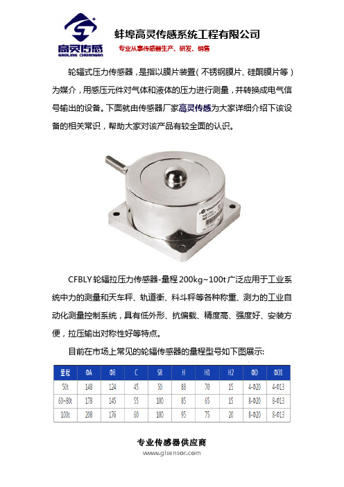
轮辐式压力传感器,是指以膜片装置(不锈钢膜片、硅酮膜片等)为媒介,用感压元件对气体和液体的压力进行测量,并转换成电气信号输出的设备。
下面就由传感器厂家高灵传感为大家详细介绍下该设备的相关常识,帮助大家对该产品有较全面的认识。
CFBLY轮辐拉压力传感器-量程200kg~100t广泛应用于工业系统中力的测量和天车秤、轨道衡、料斗秤等各种称重、测力的工业自动化测量控制系统,具有低外形、抗偏载、精度高、强度好、安装方便,拉压输出对称性好等特点。
目前在市场上常见的轮辐传感器的量程型号如下图展示:
以下是轮辐传感器的主要技术参数,可以帮助大家了解这款产品使用情况,以便能正常使用。
蚌埠高灵传感系统工程有限公司在自主创新的基础上开发生产压力传感器就是一种对气体和液体的压力进行测量并将测量结果转化成电气信号显示出来的设备。
这种设备在工业领域应用十分广泛,水利、交通、建筑、机床等行业都有所涉及,传统的压力传感器主要以大型器件构成,借助弹性构件的形状变化来测量压力的大小,这种传感器又大又重,使用起来很不方便,随着科学技术的迅速发展,半导体压力传感器应运而生,它更轻便、更准确,更能适应环境,逐渐取代了传统压力传感器。