netgear switch用法
NETGEAR 简单网络时间协议(SNTP)
简单网络时间协议(SNTP) 这一部分描述简单网络时间协议(SNTP)的特性。
概述SNTP:∙用来同步网络资源∙由网络时间协议(NTP)改编∙提供同步的网络时间戳∙可以用于广播和单播模式∙SNTP客户端使用UDP 123端口进行侦听命令行界面示例以下是使用SNTP特性的命令行示例。
示例#1: show sntp(Netgear Switch Routing) #show sntp ?Press Enter to execute the command.client Display SNTP Client Information.server Display SNTP Server Information.示例#2: show sntp client(Netgear Switch Routing) #show sntp clientClient Supported Modes: unicast broadcastSNTP Version: 4Port: 123Client Mode: unicastUnicast Poll Interval: 6Poll Timeout (seconds): 5Poll Retry: 1示例#3: show sntp server(Netgear Switch Routing) #show sntp serverServer IP Address: 81.169.155.234Server Type: ipv4Server Stratum: 3Server Reference Id: NTP Srv: 212.186.110.32 Server Mode: ServerServer Maximum Entries: 3Server Current Entries: 1SNTP Servers------------IP Address: 81.169.155.234 Address Type: IPV4Priority: 1Version: 4Port: 123Last Update Time: MAY 18 04:59:13 2005 Last Attempt Time: MAY 18 11:59:33 2005 Last Update Status: OtherTotal Unicast Requests: 1111Failed Unicast Requests: 361示例#4: Configure SNTPNETGEAR交换机没有内置的实时时钟。
NETGEAR GS110T 8-Port Gigabit Smart Switch 安装指南说明书
Installationsanleitung NETGEAR ProSafe 8-Port Gigabit Smart Switch™ mit2-Faser-SFP Uplinks GS110THier beginnenBefolgen Sie diese Anweisungen, um den GS110T Smart Switch zu installieren und mit dem Netzwerk zu verbinden. Konsultieren Sie anschließend das Software-Administrationshandbuch für den GS110T Smart Switch, um Informationen zur Konfiguration von Funktionen, wie z. B. VLANs, Spanning Tree Protocol (STP) und Quality of Service (QoS), zu erhalten.Überprüfen des PackungsinhaltsÖffnen Sie den Karton und vergewissern Sie sich, dass alle Teile enthalten sind. Im Lieferumfang ist Folgendes enthalten:• NETGEAR GS110T Smart Switch• Rutschfeste Füße zur Aufstellung auf einer Tischplatte• Netzkabel• Montageset• Installationsanleitung (dieses Dokument)• Ressourcen-CD mit dem NETGEAR Smart Control Center und der Hardware-Installationsanleitung. Ein Link zum online verfügbaren Software-Administrationshandbuch befindet sich auf der Ressourcen-CD. Installieren des SwitchesBereiten Sie die Umgebung so vor, dass alle Anforderungen im Hinblick auf Montage, Zugang, Stromversorgung und Umweltschutz erfüllt werden. Sollten Sie Fragen zu diesen Anforderungen haben, konsultieren Sie die Hardware-Installationsanleitung für den GS110T Smart Switch auf der Ressourcen-CD. Schließen Sie den Switch mithilfe einer der folgenden Methoden an:• Auf einer ebenen Fläche: Bringen Sie die Gummifüße an den vier dafür vorgesehenen Stellen an der Unterseite des Switches an.• In einem Rack: Verwenden Sie das im Lieferumfang Ihres Switches enthalteneRack-Montageset, um den Switch in einem EIA-Standard-Rack mit 19 Zoll(48,3 cm) zu installieren. Folgen Sie den Installationsanweisungen in derHardware-Installationsanleitung.Vorbereiten des administrativen ComputersBei dem administrativen Computer handelt es sich um das Windows-basierte System,mit dessen Hilfe Sie die Ersteinrichtung und -Konfiguration des Switches durchführen.Der administrative Computer muss mit einem Netzwerkadapter ausgestattet sein, dermit dem Netzwerk und einem CD-ROM-Laufwerk verbunden ist.Installieren des Smart Control Centers auf dem ComputerDas NETGEAR Smart Control Center ist eine Windows-basierte Anwendung, dieNETGEAR Smart Switches im Netzwerk erkennt und Sie bei der Durchführung vonadministrativen Aufgaben, wie z. B. Firmware-Upgrades oder der Zuweisung vonIP-Adressen, unterstützt.So installieren Sie das Smart Control Center auf dem administrativen Computer:1. Legen Sie die Ressourcen-CD in das CD-ROM-Laufwerk ein.2. Installieren Sie das Smart Control Center mithilfe des Setup-Programms. DerInstallationsassistent führt Sie durch die Installation.Anschließen des Switches an das NetzwerkWenn Sie statische IP-Adressen in Ihrem Netzwerk verwenden, konfigurieren Siemithilfe des Smart Control Centers die statische IP-Adresse des Switches, bevorSie den Switch mit Ihrem Netzwerk verbinden. Ist kein DHCP-Server vorhanden,wird dem Switch die Standard-IP-Adresse 192.168.0.239 und Subnetzmaske255.255.255.0 zugewiesen.WICHTIG! Der DHCP-Client auf dem Switch ist standardmäßig aktiviert. WennSie einen DHCP-Server verwenden, um dem Switch eine IP-Adresse zuzuweisen, müssen Sie den Switch nicht konfigurieren,bevor Sie ihn an das Netzwerk anschließen.So konfigurieren Sie den Switch und weisen ihm eine statische IP-Adresse zu,bevor Sie ihn mit Ihrem Netzwerk verbinden:1. Konfigurieren Sie eine statische IP-Adresse auf dem administrativen PC imSubnetz 192.168.0.0/24, zum Beispiel 192.168.0.1.2. Verwenden Sie ein ungeschirmtes Twisted-Pair-Kabel (UTP) der Kategorie 5(Cat5), um den Netzwerkanschluss des Computers mit einem RJ-45-Anschlussauf der Rückseite des Switches zu verbinden.3. Starten Sie das Smart Control Center auf dem PC, um den Switch zu erkennenund eine Ihrem Netzwerk entsprechende statische IP-Adresse zu konfigurieren.Weitere Informationen zu diesem Schritt erhalten Sie online im Software-Administrationshandbuch für den GS110T Smart Switch.So schließen Sie den Switch an das Netzwerk an:1. Verbinden Sie jeden PC oder andere Netzwerkgeräte, wie z. B. Drucker oderServer, mit einem RJ-45-Netzwerkanschluss auf der Vorderseite des Switches.Verwenden Sie für alle Verbindungen UTP-Kabel der Kategorie 5 (Cat5) miteinem RJ-45-Stecker.und schließen Sie das andere Ende an eine Stromquelle an, um den Switcheinzuschalten.Erkennen des Switches mithilfe des Smart ControlCentersSo erkennen Sie den GS110T Switch mithilfe des Smart Control Centers:1. Doppelklicken Sie auf das Smart Control Center-Symbol auf IhremDesktop, oder wählen Sie die Anwendung im Windows-Startmenü unter"Programme" aus, um das Programm auszuführen.2. Klicken Sie im Hauptfenster des Smart Control Centers auf Discover(Erkennen), um den Switch im Netzwerk zu finden.September 2011Dieses Symbol wurde in Übereinstimmung mit der EU-Richtlinie 2002/96/EG zu Elektro- undElektronik-Altgeräten (WEEE-Richtlinie) hier angebracht. Die Entsorgung dieses Produkts innerhalb der Europäischen Union sollte in Übereinstimmung mit den in Ihrem Land zur Implementierung der WEEE-Richtlinie geltenden Gesetzen gehandhabt werden.© 2011 NETGEAR, Inc. Alle Rechte vorbehalten. NETGEAR und das NETGEAR-Logo sind eingetrageneMarken von NETGEAR, Inc. in den USA und/oder anderen Ländern. Andere Marken- und Produktnamen sind Marken oder eingetragene Marken der jeweiligen Inhaber. Informationen können ohne vorherige Ankündigung geändert werden.Vergewissern Sie sich, dass der Switch komplett hochgefahren und betriebsbereit ist, bevor Sie auf Discover (Erkennen) klicken.Das Smart Control Center findet den Switch und zeigt dessen MAC-Adresse, IP-Adresse und Modellnummer an.Sollte Ihr Switch nicht angezeigt werden, überprüfen Sie, ob alle Kabel fest eingesteckt sind, und ob sich die Konfiguration der IP-Adresse des administrativen Computers im selben Subnetz befindet wie der Switch. Klicken Sie anschließend auf die Schaltfläche Discover (Erkennen).3. Markieren Sie per Mausklick die Zeile, die die Informationen zu Ihrem Switchenthält. Wenn sich in Ihrem Netzwerk mehrere Switches befinden, wählen Sie den Switch aus, den Sie konfigurieren möchten.Schaltfläche Web Browser Access(Webbrowser-Zugriff)Schaltfläche Discover (Erkennen)4. Klicken Sie auf Web Browser Access (Webbrowser-Zugriff), um auf demadministrativen Computer einen Webbrowser zu starten und denAnmeldebildschirm des Switches anzuzeigen. Die Dialogbox zur Anmeldung wird angezeigt.5. Geben Sie das standardmäßige Passwort (password ) in Kleinbuchstaben ein,und klicken Sie auf Login (Anmelden).Die Seite System Information (Systeminformationen) wird angezeigt.6. Konfigurieren Sie den Switch für Ihr Netzwerk.Informationen zu Switch-Funktionen und Hilfe bei Konfigurationsverfahren erhalten Sie online im Software-Administrationshandbuch .Informationen zu den einzelnen Anzeigen und konfigurierbaren Feldern erhalten Sie, indem Sie auf das Hilfesymbol klicken, das Sie auf jeder Seite der Benutzeroberfläche des Switches finden.Tipps zur Fehlerbehebung• Stellen Sie sicher, dass der GS110T Smart Switch betriebsbereit ist, bevorSie versuchen, ihn zu erkennen.Warten Sie nach dem Einschalten des GS110T Switches mindestens zwei Minuten, bevor Sie im Smart Control Center auf die Schaltfläche Discover (Erkennen) klicken.• Überprüfen Sie, ob die Kabel richtig angeschlossen sind.Für jedes eingeschaltete Gerät, das mit einem fest eingesteckten Netzwerkkabel an den Smart Switch angeschlossen ist, leuchtet die entsprechende Port-Status-LED.• Stellen Sie sicher, dass die Netzwerkeinstellungen auf demadministrativen Computer korrekt sind.In den meisten Fällen sind Computer so konfiguriert, dass die IP-Adresse automatisch über DHCP bezogen wird. Hilfe hierzu finden Sie im Software-Administrationshandbuch ; ein Link zum Online-Referenzhandbuch befindet sich auf der Ressourcen-CD.Wenn in Ihrem Netzwerk statische IP-Adressen verwendet werden, sollten Sie sicherstellen, dass der Switch und der Computer mit gültigen IP-Adressen im selben Subnetz konfiguriert wurden.Technischer SupportVielen Dank, dass Sie sich für Produkte von NETGEAR entschieden haben.Nach der Installation des Geräts können Sie das Produkt untergear.de/registrierung registrieren. Die Seriennummer finden Sie auf dem Etikett Ihres Produkts. Die Registrierung ist Voraussetzung für die Nutzung des telefonischen Supports. Die Registrierung über unsere Website wird dringend empfohlen.Produkt-Updates und Internetsupport finden Sie unter .Weitere Informationen zur Einrichtung, Konfiguration und Verwendung desSwitches finden Sie im Software-Administrationshandbuch für den Smart Switch .Die vollständige DoC finden Sie auf der NETGEAR-Website mit der EU-Konformitätserklärung unter: /app/answers/detail/a_id/11621/.。
IGMP侦听(IGMPSnooping)
Interfaces Enabled for IGMP Snooping..... 1/0/10 Vlans enabled for IGMP snooping.......... 20
示例#3: show mac-ห้องสมุดไป่ตู้ddress-table igmpsnooping
(Netgear Switch) #show mac-address-table igmpsnooping ?
Fwd: 1/0/47
00:01:01:00:5E:7F:FF:FA
Dynamic Network Assist
Fwd: 1/0/47
00:01:01:00:5E:7F:FF:FE
Dynamic Network Assist
Fwd: 1/0/47
Interfaces
Display IGMP Snooping Multicast Router information.
<1-4093>
Display IGMP Snooping valid VLAN ID information.
(Netgear Switch)#show igmpsnooping
Admin Mode............................... Enable Multicast Control Frame Count............ 0
IGMP 侦听(IGMP Snooping)
这一部分讲述因特网组管理协议(IGMP)的特性:IGMPv3和IGMP侦听。
概述
IGMP: 使用IGMPv3版本 包括IGMP侦听 IGMP侦听可以根据每个VLAN来启用
命令行界面示例
以下是使用IGMP侦听特性的命令示例。
NETGEAR Insight Managed Switches 产品说明书
Build a future-proof network with NETGEAR Insight Managed Switches • Extensive L2+/L3 Lite switching features including static routing• Comprehensive IPv6 management, QoS and ACL support, ensuring investmentprotection and a smooth migration to IPv6-based networking• Advanced QoS with IPv4/IPv6 ingress traffic filtering (ACLs) and prioritization (QoS)• Dynamic VLAN assignment for easy user authentication and location-independent access to network• Strong PoE+ power budgets of 390W(GC728XP) and 505W (GC752XP) have the flexibility to serve power-hungry devices such as 11ac Wireless APs, VoIP voice and video phones, security/surveillance cameras including PTZ, and other IoT devices • Advanced per-port PoE controls1 (setspecific power budget per port in addition to automatic class-defined) and PoE scheduling NETGEAR quality and reliability• Industry-leading 5-year Limited Hardware Warranty*• Minimal down-time with Next-Business-Day Replacement Warranty• Get deployment assistance with 90-days Free Advanced Technical Support**Innovative features for the most versatile and easy-to-manage switches in the marketYour network. Anytime. Anywhere.The NETGEAR Insight Managed Smart Cloud Switches fundamentally change the way you think of networks and IT. Using the NETGEAR Insight app with Insight Managed Smart Cloud Switches and Wireless Access Points provides:• Instant in-app discovery & set-up • Local or remote configuration andmonitoring from your mobile device, PC, Mac or tablet• Centralized network configuration polices with auto-join and configure (zero-touch provisioning)• Multi-site/remote network management and monitoring with single pane-of-glass view • Multi-switch/multi-port concurrentconfiguration using the Port Config Wizard Remote monitoring and management from the palm of your hand!With the NETGEAR Insight app, you can setup, manage, and monitor your networks from anywhere, anytime, from the palm of your hand on your phone or tablet! Or, for a larger screen experience, you can use the Insight Cloud Portal from your PC, Mac, or tablet web browser.Network-centric configuration and managementNETGEAR Insight Managed Switches and Wireless Access Points using the NETGEAR Insight app allow for cross-device automated configuration of VLANs, QoS, ACLs, and LAGs. Auto-join and configure (zero-touch privisioning) allows for additional devices added seamlessly.Fully-integrated cloud-manageable devices NETGEAR Insight Managed switches arefully-integrated, cloud-manageable, plug-and-play devices. Just connect to your network and without any setup, they’re passing traffic. For configuration setup, management, and monitoring, you can use the Insight mobile app on your mobile device or the Insight Cloud Portal from your PC, Mac, or tablet web browser. No additional cloud controller, appliance, network manager, or on-premise cloud server necessary.Clean, sleek silent (or whisper-quiet) designs Insight Managed switches have a modern, clean design, with at-a-glance cloud, power, fan, and PoE max1 LEDs for quick status monitoring. On-port LEDs for link/activity and PoE power 1 allow for port-specific connectivity monitoring.Connectivity options for every environment GC728X and GC728XP have 24 copper Gigabit Ethernet ports; GC752X andGC752XP have 48 copper Gigabit Ethernet ports. All models also have two dedicated 1G SFP fiber ports, and two dedicated 10G SFP+ fiber ports for maximum connectivity. On PoE+ models (GC728XP and GC752XP), all Gigabit Ethernet copper ports support PoE or PoE+, with a PoE power budget of 390W (GC728XP) and 505W (GC752XP). Dedicated Gigabit SFP and 10G SFP+ ports provide fiber uplinks for server interconnects or across long distances, or can be used to build dual redundancy by a trunked uplinkwith link aggregation and failover.Insight Managed Gigabit Ethernet/10G SFP+ Smart Cloud Switches Data SheetGC728X, GC728XP, GC752X, GC752XPExperience the most versatile and easy to manage switches in the marketAs a leading provider of network equipment for SMBs, NETGEAR® understands theimportance of reliable and high performance networks. With the growth of virtualization, cloud-based services and applications like VoIP, video streaming and IP surveillance, SMB networks need to extend beyond simple reliability to simpler management and remote monitoring to ensure your network is “always up”. NETGEAR also understands that small business owners shouldn’t have to understand networking and IT; they need a network that’s easy-to-setup and is reliable, so they can focus on their business, not theirnetwork. To that end, NETGEAR is introducing our most versatile and easy-to-manage switches ever, NETGEAR Insight Managed Smart Cloud switches.The Insight Managed Smart Cloud Gigabit Ethernet Switches are the first switches from NETGEAR with anywhere configuration and management. Using either the NETGEAR Insight app on your mobile device or tablet, or the Insight Cloud Portal from your PC, Mac, or tablet, you can quickly discover, setup, monitor and manage your Smart Cloud Switches from anywhere in the world! With their remote cloud manageability, sleek design silent or whisper-quiet operation, they are the most versatile switches in the market for any environment.Whether at home, out of the office or on a business trip, you can still manage and monitor your network as if you were right there.Hardware at a GlanceGC728X: 28-Port Gigabit Ethernet Insight Managed Smart Cloud Switch w/2 SFP and 2 SFP+ 10G Fiber Ports• 24 x 1000BASE-T Copper ports supporting 1G/100M speeds • 2 x 1000BASE-X Dedicated SFP Fiber ports• 2 x 10GBASE-X Dedicated SFP+ Fiber ports supporting 10G/1G speeds • Max 28dB @ 25°C / 77°F ambientGC752X: 52-Port Gigabit Ethernet Insight Managed Smart Cloud Switch w/2 SFP and 2 SFP+ 10G Fiber Ports• 48 x 1000BASE-T Copper ports supporting 1G/100M speeds • 2 x 1000BASE-X Dedicated SFP Fiber ports• 2 x 10GBASE-X Dedicated SFP+ Fiber ports supporting 10G/1G speeds • Max 25dB @ 25°C / 77°F ambientGC728XP: 28-Port Gigabit Ethernet PoE+ Insight Managed SmartCloud Switch w/2 SFP and 2 SFP+ 10G Fiber Ports• 24 x 1000BASE-T PoE+ Copper ports supporting 1G/100M speeds • 2 x 1000BASE-X Dedicated SFP Fiber ports• 2 x 10GBASE-X Dedicated SFP+ Fiber ports supporting 10G/1G speeds • 390W PoE budget (max 39dB @ 25°C / 77°F ambient)GC752XP: 52-Port Gigabit Ethernet PoE+ Insight Managed SmartCloud Switch w/2 SFP and 2 SFP+ 10G Fiber Ports• 48 x 1000BASE-T PoE+ Copper ports supporting 1G/100M speeds • 2 x 1000BASE-X Dedicated SFP Fiber ports• 2 x 10GBASE-X Dedicated SFP+ Fiber ports supporting 10G/1G speeds• 505W PoE budget (max 30dB @ 25°C / 77°F ambient)Insight Managed Gigabit Ethernet/10G SFP+ Smart Cloud SwitchesData SheetGC728X, GC728XP, GC752X, GC752XPPerformance at a GlanceSoftware at a GlanceOrdering InformationInsight Managed Gigabit Ethernet/10G SFP+ Smart Cloud SwitchesData SheetGC728X, GC728XP, GC752X, GC752XPInsight Managed Gigabit Ethernet/10G SFP+ Smart Cloud Switches Data SheetGC728X, GC728XP, GC752X, GC752XP Features and BenefitsInsight Managed Gigabit Ethernet/10G SFP+ Smart Cloud Switches Data SheetGC728X, GC728XP, GC752X, GC752XPWhy Insight Managed Smart Cloud Switches?NETGEAR is revolutionizing unified, centralized network management with it’s new line of Insight Managed Smart Cloud Switches and Wireless Access Points, all managed from the palm of your hand, anytime, anywhere, on your phone or tablet using the NETGEAR Insight mobile app. Or, for a larger screen experience, from your PC, Mac, or tablet web browser using the Insight Cloud Portal.• Ideal for SMBs, offices, retail stores, education, healthcare, owner-operated businesses, etc.• IT expert or no networking experience at all: Insight Managed Smart Cloud Switches let you focus on your business, not maintaining your network.• Know immediately if and when your network is not running perfectly; not after you’ve already lost business or suffered significant down-time.• Advanced L2+/L3 Lite network features such as IPv4/IPv6 management, VLANs, DiffServ QoS, LACP Link Aggregation, Spanning Tree, Static Routing, advanced per-port PoE controls and PoE scheduling will satisfy even the most advanced small business networks.• Fundamentally change and simplify network usability for easier and smoother deployment of voice, video, and WLAN on the same converged platform.• Industry-leading 5-year warranty on switches, 5-year Next-Business-Day (NBD) replacement, and 90-days free technical support** for peace-of-mind. Extended ProSUPPORT service plans available for purchase.Within small and medium-sized organizations, there is growing adoption of PoE devices such as VoIP phones, IP security cameras, wireless access points, proximity sensors, LED lighting, door locks, and other IoT devices that require network switches capable of supporting dense PoE installations. Wireless access points and pan-tilt-zoom HD cameras using Wave 2 802.11ac Wi-Fi also require PoE+ power (802.3at), increasing the power demands on PoE switches. With a generous power budget of 390W (GC728XP) and 505W (GC752XP), the PoE versions are designed to meet the current and future needs of wireless converged networks.Example ApplicationsIn a Business/Retail EnvironmentServerGC728XReadyNAS w/MilestoneNon PoE Printer10G SFP+ FiberIn a Small Office/Workgroup Environment (Aggregation/Core Switch)Insight Managed APsSecurity CamerasGC110PPoE+PoEVoIP PhonesPC GC728XPInsight Managed Gigabit Ethernet/10G SFP+ Smart Cloud Switches Data SheetGC728X, GC728XP, GC752X, GC752XPExample ApplicationIn a Security and Surveillance EnvironmentSecurity CamerasPan and ZoomGC752XPPort configuration and monitoring Large screen access via Insight Cloud PortalNetwork dashboardSingle pane-of-glass view of multiple networks/locationsInsight Managed Gigabit Ethernet/10G SFP+ Smart Cloud SwitchesData SheetGC728X, GC728XP, GC752X, GC752XPInsight Managed Gigabit Ethernet/10G SFP+ Smart Cloud Switches Data SheetGC728X, GC728XP, GC752X, GC752XP Technical Specifications2448Insight Managed Gigabit Ethernet/10G SFP+ Smart Cloud Switches Data SheetGC728X, GC728XP, GC752X, GC752XP Technical SpecificationsInsight Managed Gigabit Ethernet/10G SFP+ Smart Cloud Switches Data SheetGC728X, GC728XP, GC752X, GC752XP Technical SpecificationsInsight Managed Gigabit Ethernet/10G SFP+ Smart Cloud Switches Data SheetGC728X, GC728XP, GC752X, GC752XP Technical SpecificationsInsight Managed Gigabit Ethernet/10G SFP+ Smart Cloud Switches Data SheetGC728X, GC728XP, GC752X, GC752XP Technical SpecificationsInsight Managed Gigabit Ethernet/10G SFP+ Smart Cloud Switches Data SheetGC728X, GC728XP, GC752X, GC752XP Technical SpecificationsInsight Managed Gigabit Ethernet/10G SFP+ Smart Cloud Switches Data SheetGC728X, GC728XP, GC752X, GC752XP Technical SpecificationsInsight Managed Gigabit Ethernet/10G SFP+ Smart Cloud Switches Data SheetGC728X, GC728XP, GC752X, GC752XP Technical SpecificationsOrdering InformationOrdering Information*This product comes with a limited warranty that is valid only if purchased from a NETGEAR authorized reseller, and modifications to product may void the warranty; covers hardware, fans, and internal power supplies—not software or external power supplies; see /about/warranty/ for details.** The NETGEAR OnCall 24x7 contract provides unlimited phone, chat and email technical support for your networking product.NETGEAR, the NETGEAR Logo, and NETGEAR Insight are trademarks of NETGEAR, Inc. in the United States and/or other countries. Other brand names mentioned herein are for identification purposes only and may be trademarks of their respective holder(s). Information is subject to change without notice. © 2018 NETGEAR, Inc. All rights reserved. NETGEAR,Inc.350E.PlumeriaDrive,SanJose,CA95134-1911USA,1-888-NETGEAR(638-4327),E-mail:****************,DS-GC728X/GC728XP/GC752X/GC752XP-1Insight Managed Gigabit Ethernet/10G SFP+ Smart Cloud SwitchesData SheetGC728X, GC728XP, GC752X, GC752XP。
netgear无线路由器设置以及设置密码
netgear无线路由器设置以及设置密码随着互联网的普及和应用的需求增加,无线路由器成为了现代家庭和办公场所必备的网络设备之一。
Netgear作为一家知名的网络设备制造商,其无线路由器产品在市场上非常受欢迎。
本文将为您介绍如何设置Netgear无线路由器并设置密码,以确保网络的安全和稳定。
第一步:连接和设置1. 确保您的Netgear无线路由器已正确连接到电源并且开启。
您可以通过观察路由器的指示灯来确认电源是否正常工作。
2. 将您的电脑或移动设备与Netgear无线路由器进行连接。
您可以使用无线连接或者通过网线连接到路由器的LAN接口。
3. 打开您的浏览器,输入默认的路由器IP地址。
通常情况下,Netgear路由器的默认IP地址为192.168.1.1或者192.168.0.1。
按下回车键进入路由器的管理界面。
4. 输入您的管理员用户名和密码。
默认情况下,Netgear路由器的用户名为"admin",密码为空。
如果您之前更改过这些信息,请使用您所设置的用户名和密码进行登录。
第二步:基本设置1. 在路由器的管理界面中,找到“基本设置”或类似的选项。
在这个页面上,您可以配置路由器的基本网络设置。
2. 首先,在“Internet连接类型”或“WAN设置”中选择您的网络连接类型。
如果您是通过电缆或DSL接入互联网,选择动态IP。
如果您是通过宽带账号登录,选择PPPoE。
3. 根据您的网络服务提供商的要求,输入相应的网络设置信息,比如IP地址、子网掩码、默认网关和DNS服务器。
4. 然后,设置无线网络名称(SSID)。
您可以设置一个易于记忆的名称,并确保启用无线网络。
5. 设置无线网络的安全性。
选择WPA2-PSK(当前较为安全的加密方式),并设置一个强密码。
密码应包含大小写字母、数字和特殊字符,并且足够长以提高安全性。
6. 保存并应用更改。
路由器将重新启动并应用新的设置。
第三步:高级设置1. 在路由器管理界面中,找到“高级设置”或类似的选项。
NETGEAR 网络开关安装指南说明书
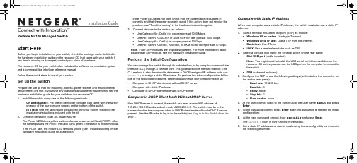
Installation GuideIf the Power LED does not light, check that the power cable is plugged incorrectly and that the power source is good. If this action does not resolve the problem, see “Troubleshooting” in the hardware installation guide.3. Connect devices to the switch, as follows:• Use Category 5e (Cat5e) for copper ports at 1000 Mbps.• Use NETGEAR AGM731F or AGM732F for fiber ports at 1000 Mbps.• Use Category 6A (Cat6a) for copper ports at 10 Gbps.• Use NETGEAR AXM761, AXM762, or AXM763 for fiber ports at 10 Gbps.Note:Fiber SFP modules are shipped separately. For more information about installing an SFP module, see the hardware installation guide.Perform the Initial ConfigurationYou can manage this switch through its web interface, or by using the command-line interface (CLI) through a console port. This guide describes the web method. The CLI method is also described to determine a DHCP-assigned IP address or to use ezconfig to assign a static IP address. To perform the initial configuration, follow one of the following procedures, depending upon how your computer is set up:• Computer in DHCP client mode without DHCP server • Computer with static IP address• Computer in DHCP client mode with DHCP serverComputer in DHCP Client Mode Without DHCP ServerIf no DHCP server is present, the switch assumes a default IP address of169.254.100.100 and a subnet mask of 255.255.0.0. The switch must be in the same subnet as the computer when in DHCP-client mode without a DHCP server present. Use this IP value to log in to the switch (see “Log in to the Switch from the Web ”).Computer with Static IP AddressWhen your computer uses a static IP address, the switch must also use a static IP address.1. Start a terminal emulation program (TEP) as follows:• Windows XP or earlier . Use HyperTerminal.• Windows Vista or later . Use a TEP from the Internet.• Macintosh . Use ZTerm.• UNIX . Use a terminal emulator such as TIP.2. Select a console port using the console switch on the rear panel:• Mini USB port (cable included).Note: You might need to install the USB serial port driver available on the resource CD before you can use the USB port on the computer to connect to the switch.• DB9 (cable not included).3. Configure the TEP to use the following settings (written below the connector onthe switch rear panel):• Baud rate . 115200 bps • Data bits . 8• Parity . none • Stop bits . 1• Flow control . none 4. At the user prompt, log in to the switch using the user name admin and pressEnter .5. At the password prompt, press Enter again (no password is needed for initialconfiguration).6. At the next command prompt, type ezconfig and press Enter .The ezconfig utility is now running in the switch.7. Set a static IP address and subnet mask using the ezconfig utility as shown inthe following example.ProSafe M7100 Managed SwitchStart HereBefore you begin installation of your switch, check the package contents listed in the hardware installation guide on the resource CD that came with your switch . If any item is missing or damaged, contact your place of purchase.The resource CD for your switch also includes the software administration guide and a command-line interface reference manual.Follow these quick steps to install your switch.Set up the SwitchPrepare the site so that the mounting, access, power source, and environmental requirements are met. If you have any questions about these requirements, see the hardware installation guide for your switch on the resource CD .1. Install the switch using one of the following methods:• On a flat surface . Put one of the rubber footpads that came with the switch on each of the four concave spaces on the bottom of the switch.• In a rack . Use the rack-mount kit supplied with your switch, following the installation instructions included with the kit.2. Connect the switch to an AC power source.The Power LED blinks yellow as it conducts a power-on self-test (POST). After the switch passes the POST, the LED turns green. The switch is now functional.If the POST fails, the Power LED remains yellow (see “Troubleshooting” in the hardware installation guide for assistance).November 2012This symbol was placed in accordance with the European Union Directive 2002/96 on the Waste Electrical and Electronic Equipment (the WEEE Directive). If disposed of within the European Union, this product should be treated and recycled in accordance with the laws of your jurisdiction implementing the WEEE Directive.©2012 by NETGEAR, Inc. All rights reserved. NETGEAR and the NETGEAR logo are registered trademarks of NETGEAR, Inc. in the United States and/or other countries. Other brand and product names are trademarks orregistered trademarks of their respective holders. Information is subject to change without notice.For the complete EU Declaration of Conformity, visit/app/answers/detail/a_id/11621/.For indoor use only in all EU countries and Switzerland.8. Use the switch IP address returned by ezconfig to log in to the switch.See Log in to the Switch from the Web .For information about how to perform extensive CLI management, see both the CLI reference manual for your switch and the software administration guide.(switch) #ezconfigEZ Configuration Utility--------------------------------Hello and Welcome!This utility will walk you thru assigning the IP address for the switch management CPU. It will allow you to save the changes at the end. After the session, simply use the newly assigned IP address to access the Web GUI using any public domain Web browser.Admin password is not defined.Do you want to assign the admin password (password length should vary in a range of 8 - 64 characters)? (Y/N/Q)The 'enable' password required for switch configuration via the command line interface is currently not configured.Do you want to assign it (password length should vary in a range of 8 - 64 characters) (Y/N Q)? nAssigning an IP address to your switch management Current IP Address Configuration --------------------------------IP Address Assignment Mode: None IP Address: 0.0.0.0Subnet mask: 0.0.0.0Default Router IP: 0.0.0.0IP address is not assigned. What do you want to do?C - Configure IP address manually.D - Assign IP address for the switch using DHCP mode(current IP address will be lost).N - Do nothing and go to the next question.Q - Quit. - Help.(C/D/N/Q/?)? cIP Address: 10.10.10.1Network mask: 255.255.255.0Default Router IP: 10.10.10.254Assigning System Name, System Location and System Contact to your switch management Current Configuration--------------------------------System Name:System Location:System Contact:Do you want to apply and save the changes (Y/N)? y Config file 'startup-config' created successfully .The configuration changes have been applied and saved.Please enter 'show running-config' to see the final configuration.Computer in DHCP Client Mode with DHCP ServerBy default, the switch is configured as a DHCP client to obtain its IP address from a DHCP server in the connected network. You need to access the switch from theserial console port.1. Make sure that the switch is connected to a DHCP server.2. Find the switch IP address assigned by the DHCP server.a. Perform steps 1 through 3 of the procedure Computer with Static IP Address .b. Type the show network command, and press Enter . A screen displaysthat shows the active switch IP address.c. Use this IP address to log in to the switch through its web management interface (see Log in to the Switch from the Web ).Log in to the Switch from the WebUse your switch's IP address to access the web-based management interface.1. Type http://<ipaddress> into the URL field of your browser.A screen similar to the following displays.2. Type admin for the user name, leave the password field blank, and clickLOGIN .The System Information screen displays. You can use the web-based management interface to configure your switch.Technical SupportAfter installing your device, locate the serial number on the label of your product and use it to register your product at https:// .You must register your product before you can use NETGEAR telephone support.NETGEAR recommends registering your product through the NETGEAR website. For product updates and web support, visit .NETGEAR recommends that you use only the official NETGEAR support resources. You can get the product manuals online at or through a link in the product’s user interface.WARNING!!Do not stack equipment, or place equipment in tight spaces, in drawers, or oncarpets. Make sure that your equipment has at least 2 inches (5 cm) of air space on all sides.。
NETGEAR Smart Switch GS516TP 安装指南说明书
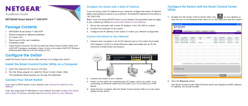
Installation GuideNETGEAR Smart Switch™ GS516TPPackage Contents•NETGEAR Smart Switch™ GS516TP•Rubber footpads for tabletop installation•AC power cord•Rack-mount kit for rack installation•Installation guide•Smart Switch resource CD that includes the Smart Control Center Utility and GS516TP Hardware Installation Guide. (A link to the online GS516TP Software Administration Manual is on the resource CD.)Configure the SwitchInstall the Smart Control Center Utility and use it to configure the switch.Install the Smart Control Center Utility on a Computer1.Insert the resource CD into your CD drive.2.Run the Setup program to install the Smart Control Center Utility.The Installation Wizard guides you through the installation.Connect Your Smart SwitchIf you have a DHCP server in your network, see Connect the Switch to Your Network.If you are using static IP addresses in your network, first see Configure the Switch with a Static IP Address, and then see Connect the Switch to Your Network. Configure the Switch with a Static IP AddressIf you are using a static IP address in your network, configure the switch IP addressbefore connecting the switch to your network. The default IP address of the switch is192.168.0.239.Note: If you are using a DHCP server in your network, this procedure does not applyto you; instead, go directly to Connect the Switch to Your Network.1.Set up the computer with a static IP address in the 192.168.0.x subnet.2.Connect the computer to the switch.3.Configure the IP address of the switch to match your network configuration.Connect the Switch to Your Network1.Connect each computer to an RJ-45 network port on the switch front panel.Use Category 5 (Cat 5) or better Ethernet cable terminated with an RJ-45connector to make these connections.2.3.Power on the switch by connecting the AC power cord to an outlet, or byconnecting an Ethernet cable from PD ports 15 or 16 (or both) to a PSEdevice.4.Verify that the computer with the Smart Control Center Utility is on the samesubnet as the switch.Configure the Switch with the Smart Control CenterUtility1.Double-click the Smart Control Center Utility icon on your desktop orclick the icon in the Windows Start menu to run the utility and view this screen.2.Click the Discover button.The Smart Control Center Utility finds the switch and displays its MAC address,IP address, and model number.May 2013NETGEAR, the NETGEAR logo, and Connect with Innovation are trademarks and/or registered trademarks of NETGEAR, Inc. and/or its subsidiaries in the United States and/or other countries. Information is subject to change without notice. © NETGEAR, Inc. All rights reserved.NETGEAR, Inc.350 East Plumeria Drive San Jose, CA 95134 USAIf the utility does not discover your switch, verify that the cable connections are secure and that the IP address configuration of the computer is in the same subnet as the switch, and click the Discover button.3.Click the row for the switch that you want to configure.4.Click the Web Browser Access buttonto view the switch Login screen.5.Enter the default password of password in lower-case letters and click theLogin button.The System Information screen displays.6.Configure the switch for your network.For more information, see the GS516TP Software Administration Manual.Troubleshooting TipsHere are some tips for correcting simple problems you might have.•Be sure to power on your computer and switch in the following sequence: 1. Turn on the switch and wait about two minutes. 2. Turn on the computer and connect to the switch. •Make sure the Ethernet cables are plugged in.For each powered-on computer connected to the switch, the corresponding switch LAN port status LED is lit.•Make sure the network settings of the computer are correct.In most cases, computers should be configured to obtain an IP address through DHCP .If your network uses static IP addresses, be sure that the switch and computer are configured with valid IP addresses. For more information, see the software administration manual.SupportThank you for selecting NETGEAR products.After installing your device, locate the serial number on the label of your product and use it to register your product at https:// .You must register your product before you can use NETGEAR telephone support. NETGEAR recommends registering your product through the NETGEAR website. For product updates and web support, visit .NETGEAR recommends that you use only the official NETGEAR support resources.For additional information about setting up, configuring, and using your smart switch, see the software administration manual . You can get the manual online at .。
NETGEAR Gigabit Ethernet Unmanaged Switch 安装指南说明书
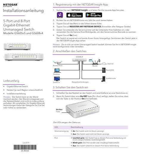
InstallationsanleitungJuli 2019Lieferumfang• Gigabit Ethernet Switch• Netzteil (je nach Region unterschiedlich)•InstallationsanleitungHinweis: Der Switch kann an der Wandmontiert werden. Der Wandmontagesatz und die Netzwerkkabel sind nicht im Lieferumfang enthalten. Wir empfehlen, für Gigabit-Ethernet-Verbindungen Kabel der Kategorie 5e (Cat 5e) oder höher zu verwenden.5-Port und 8-Port Gigabit-Ethernet Unmanaged SwitchModelle GS605v5 und GS608v41. Registrierung mit der NETGEAR Insight App1. Suchen Sie nach NETGEAR Insight , und laden Sie die neueste App herunter.2. Richten Sie ein NETGEAR Konto ein, falls Sie noch keines haben.3. Tippen Sie auf das Menü in der linken oberen Ecke.4. Tippen Sie auf REGISTER ANY NETGEAR DEVICE (Anmelden aller Netgear Geräte).5. Geben Sie entweder die Seriennummer auf der Unterseite Ihres Switches ein, oderverwenden Sie die Kamera Ihres Mobilgeräts, um den Seriennummer-Barcode zu scannen.6. Tippen Sie auf Go (Los).Der Switch ist registriert und wurde Ihrem Konto hinzugefügt. Sie können den Switch jetzt in der NETGEAR Insight App sehen.Hinweis: Da es sich um einen Unmanaged Switch handelt, können Sie ihn in NETGEAR Insight nicht konfigurieren oder verwalten.2. Anschließen des SwitchesInternetSpielkonsolePort• Leuchtet grün : Der Switch hat an diesem Port eine Verbindung mit einem eingeschalteten Gerät festgestellt.• Blinkt grün : Der Port sendet oder empfängt Datenverkehr.• Aus : Der Switch erkennt an diesem Port keine Verbindung.SupportVielen Dank, dass Sie sich für dieses NETGEAR Produkt entschieden haben. Besuchen Sie https:///support , um Ihr Produkt zu registrieren, Support und Zugriff auf die neuesten Downloads zu erhalten oder unserer Community beizutreten. Wir empfehlen, ausschließlich offizielle NETGEAR Support-Ressourcen zu nutzen.Informationen zur Einhaltung der rechtlichen Vorschriften, einschließlich der EU-Konformitätserklärung, finden Sie unter: https:///about/regulatory/.Lesen Sie das Dokument zur Einhaltungrechtlicher Vorschriften, bevor Sie das Gerät an die Stromversorgung anschließen.Verwenden Sie dieses Gerät nicht inAußenbereichen. Wenn Sie Kabel oder Geräte anschließen, die sich in Außenbereichen befinden, beachten Sie die Sicherheits- und Garantieinformationen unterhttps:///000057103.Technische DatenTechnische DatenBeschreibungBetriebstemperatur 0 °C bis 40 °C GS605v5-Netzteilausgang 5 VDC, 0,7 A GS608v4-Netzteilausgang12 VDC, 0,5 ANETGEAR, Inc.350 East Plumeria Drive San Jose, CA 95134, USA© NETGEAR, Inc., NETGEAR und das NETGEAR Logo sind Marken von NETGEAR, Inc. Jegliche nicht zu NETGEAR gehörende Marken werden nur zu Referenzzwecken verwendet.NETGEAR INTERNATIONAL LTD Floor 1, Building 3University Technology Centre Curraheen Road, Cork,T12EF21, Ireland。
NETGEAR 网络开关连接指南说明书
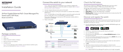
Connect the switch to your network Note: If you are using static IP addresses in your network, configure theswitch IP address before you connect the switch to a network. See Configure the switch with a static IP address .1. Connect network devices to the ports on the switch.2. Connect an RJ-45 port or SFP port on the switch to a network that includes aDHCP server.Note: In a small office or home office network, connect the switch to the LAN port of a router that, in turn, is connected to an Internet modem.If you use an SFP port, you must insert an SFP transceiver module, which is available from NETGEAR.3. Power on the switch.Check the PoE statusThe switch can supply up to 30W PoE+ (IEEE 802.3at) to each port, with a maximum PoE power budget of 190W across all active PoE+ ports.The PoE Max LED indicates the status of the PoE budget on the switch:• Off . Sufficient. More than 7W of PoE power is available.• Solid yellow . Less than 7W of PoE power is available.• Blinking yellow . At least once during the previous two minutes, less than 7Wof PoE power was available.Discover and register the switchIf the switch is connected to a WiFi router or access point and to the Internet, you can use the NETGEAR Insight app to discover the switch in your network, register the switch with NETGEAR, and activate your warranty.1. On your mobile device, visit the app store, search for NETGEAR Insight, anddownload the latest version of the app.2. Connect your mobile device to the same WiFi network as the switch.3. Open the NETGEAR Insight app.4. If you did not set up a NETGEAR account, tap Create NETGEAR Account and followthe onscreen instructions.5. Enter the email address and password for your account and tap LOG IN . After you login to your account, the switch displays in the devices list.6. Tap + in the upper right corner.7. Either use the camera on your phone to scan the serial number bar code located onthe bottom of the switch, or enter the serial number.8. Tap Go .9.Follow the onscreen instructions to add your switch to a network location.10. The switch is registered and added to your NETGEAR account. You can now view andmonitor the switch.24-Port Gigabit Ethernet PoE+ Smart Managed Pro Switch with 2 SFP PortsModel GS724TPv2Package contents• Switch • Power cord• Rubber footpads for tabletop installation • Rack-mount kit for rack installation •Installation guideNote: For more information about installation, see the hardware installation guide, which you can download from /support/.Sample connectionsNetworkInternetGS724TPv2Line ColorDescriptionBlue PoE (such as VoIP phones and security cameras)Green PoE+ (such as WiFi access points) BlackInternetWifi RouterPoE VoIP phoneSecurity CameraNETGEAR, Inc.350 East Plumeria Drive San Jose, CA 95134, USANETGEAR INTERNATIONAL LTD Floor 1, Building 3University Technology Centre Curraheen Road, Cork, T12EF21, Ireland© NETGEAR, Inc., NETGEAR and the NETGEAR Logo are trademarks of NETGEAR, Inc. Any non‑NETGEAR trademarks are used for reference purposes only.SupportThank you for purchasing this NETGEAR product. You can visithttps:///support/ to register your product, get help, access the latest downloads and user manuals, and join our community. We recommend that you use only official NETGEAR support resources.Si ce produit est vendu au Canada, vous pouvez accéder à ce document en français canadien à https:///support/download/.(If this product is sold in Canada, you can access this document in Canadian French at https:///support/download/.)For regulatory compliance information including the EU Declaration of Conformity, visit https:///about/regulatory/.See the regulatory compliance document before connecting the power supply.Do not use this device outdoors. If you connect cables or devices that are outdoors to this device, see https:///000057103 for safety and warranty information.September 2019Configure the switch with a static IP addressNote: If your network uses a DHCP server, this section does not apply . If you are using static IP addresses in your network, configure the switch IP address before you connect the switch to a network.1. Configure a computer with a static IP address in the 192.168.0.x subnet. 2. Power on the switch, and connect your computer to the switch using anEthernet cable.3. Open a web browser and enter 192.168.0.239 in the address bar.(The default IP address of the switch is 192.168.0.239.) A login page displays.4. Enter password for the password.The System Information page displays.5. Select System > Management > IP Configuration . Select the Static IPAddress radio button.6. Enter the static IP address, subnet mask, and default gateway IP address thatyou want to assign to the switch and click the Apply button.Your settings are saved.Configure the switchTo configure the switch either:• Use the local browser browser–based interface.• Install the NETGEAR Switch Discovery Tool on your Mac or a 64-bit Windows-based computer.•Install the Smart Control Center utility on your Windows-based computer.Access the local browser interface1. For initial configuration, open a web browser on a computer that is on thesame network and subnet as the switch and enter the switch’s IP address.If you are unsure how to determine the IP address of the switch, you can use the Smart Control Center utility.2. A login page displays. Enter password for the password.The System Information page displays.3. Configure the switch for your network.For information about switch configuration, see the user manual for your switch, which you can download from /support/.Other discovery and configuration methodsThe NETGEAR Switch Discovery Tool and the Smart Control Center utility let you discover the IP address and configure the switch. •NETGEAR Switch Discovery Tool . You can use a Mac or a 64-bit Windows-based computer on the same network as the switch. To download this tool, visit /support/product/netgear-switch-discovery-tool.aspx •Smart Control Center utility . You can use a Windows-based computer on the same network as the switch. To download this utility, visit /support/product/SCC .Troubleshooting tipsHere are some tips for correcting simple problems that might occur.•Be sure to power on your computer and switch in the following sequence:a. Turn on the switch and wait about two minutes.b. Turn on the computer and connect it to the switch.•Make sure the Ethernet cables are plugged in.For each powered-on computer connected to the switch, the corresponding switch LAN port status LED is lit.•Make sure the network settings of the computer are correct.In most cases, computers should be configured to obtain an IP addressthrough DHCP . If your network uses static IP addresses, be sure that the switch and computer are configured with valid IP addresses. For more i nformation, see the user manual.。
NETGEAR FS752TP Smart Switch 安装指南说明书
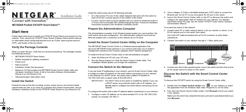
Installation GuideNETGEAR ProSafe FS752TP Smart Switch™Start HereFollow these instructions to install your FS752TP Smart Switch and connect it to the network. Then, consult the FS752TP Smart Switch Software Administration Manual for information about configuring features such as VLANs, spanning tree protocol (STP), and Quality of Service (QoS).Verify the Package ContentsWhen you open the box, verify that you received everything. The package includes the following contents:• NETGEAR FS752TP Smart Switch• Rubber footpads for tabletop installation • Power cord • Rack-mount kit• Installation Guide (this document)• Resource CD that includes the NETGEAR Smart Control Center utility andHardware Installation Guide . A link to the online Software Administration Manual is on the Resource CD.• Warranty/Support Information Card.Install the SwitchPrepare the site so that the mounting, access, power source, and environmental requirements are met. If you have any questions about these requirements, see the Hardware Installation Guide for the FS752TP Smart Switch on your Resource CD.Install the switch using one of the following methods:• On a flat surface: Put one of the rubber footpads that came with the switch oneach of the four concave spaces on the bottom of the switch.• In a rack: Use the rack-mount kit supplied with your switch to install the switch ina 19-inch (48.3-centimeter) EIA standard equipment rack. Follow the installation instructions included in the Hardware Installation Guide.Prepare the Administrative ComputerThe administrative computer is the Windows-based system you use to perform the initial switch setup and configuration. The administrative computer must have an Ethernet adapter with a connection to the network and a CD drive.Install the Smart Control Center Utility on the ComputerThe NETGEAR Smart Control Center is a Windows-based application that discovers NETGEAR Smart switches in your network and helps you to perform management operations like firmware upgrades and IP address assignment. To install the Smart Control Center utility on the administrative computer:1. Insert the Resource CD into your CD drive.2. Run the Setup program to install the Smart Control Center utility. TheInstallation Wizard guides you through the installation.Connect the Switch to the NetworkIf you use static IP addressing in your network, use the Smart Control Center utility to configure a static IP address on the switch before connecting it to your network. In the absence of a DHCP server, the switch uses a default IP address of 192.168.0.239 with a subnet mask of 255.255.255.0.IMPORTANT! The DHCP client on the switch is enabled by default. If you usea DHCP server to provide the switch with an IP address, you do not need to configure the switch before connecting it to the network. To configure the switch with a static IP address before connecting it to your network:1. Configure a static IP address on the administrative PC in the 192.168.0.0/24subnet, for example 192.168.0.1.2. Use a category 5 (Cat5) unshielded twisted-pair (UTP) cable to connect theEthernet port on the PC to any front-panel RJ-45 port on the switch.3. Launch the Smart Control Center utility on the PC to discover the switch andconfigure the appropriate static IP address for your network. For detailed information about this step, see the online FS752TP Smart Switch Software Administration Manual .To connect the switch to the network:1. Connect each PC or other network device, such as a printer or server, to anRJ-45 network port on the switch front panel.Use Cat5 UTP cable terminated with an RJ-45 connector to make these connections.2. Connect the switch to your network through a 1 Gbps uplink port.3. Connect one end of the supplied power cord to the switch and the other end toan AC power source to power on the switch.Discover the Switch with the Smart Control Center UtilityTo discover the FS752TP switch by using the Smart Control Center utility:1. Double-click the Smart Control Center icon on your desktop or selectthe application from the Windows Start menu Programs to run the utility.2. From the main Smart Control Center screen, click Discover to find your switchin the network.Make sure the switch has completed its boot cycle and is operational before you clickDiscover.FS752TPServers Computers PrintersNetworkApril 2011This symbol was placed in accordance with the European Union Directive 2002/96 on the Waste Electrical and Electronic Equipment (the WEEE Directive). If disposed of within the European Union, this product should be treated and recycled in accordance with the laws of your jurisdiction implementing the WEEE Directive.©2011 by NETGEAR, Inc. All rights reserved. NETGEAR and the NETGEAR logo are registered trademarks of NETGEAR, Inc. in the United States and/or other countries. Other brand and product names are trademarks or registered trademarks of their respective holders. Information is subject to change without notice.The Smart Control Center utility finds the switch and displays information such as its MAC Address, IP Address, and model number.If you cannot view your switch, verify that the cable connections are secure and that the IP address configuration of the administrative computer is in the same subnet as the switch. Then click the Discover button.3. Click to select the line displaying the details of your switch. If there are multipleSmart Switches in your network, be sure to select the one you want to configure.Web Browser Access ButtonDiscover Button4. Click Web Browser Access to launch a Web browser on the administrativecomputer and view the switch log in screen. The Login dialog appears.5. Enter the default password of password in lowercase letters and click Login .The System Information page appears.6. Configure the switch for your network.For information about switch features and for assistance with configuration procedures, consult the online FS752TP Smart Switch Software Administration Manual.For information about each field to view or configure, click the help iconavailable on each page of the switch user interface.Troubleshooting Tips• Make sure the FS752TP Smart Switch is operational before you attempt todiscover it.After you power up the FS752TP switch, wait at least two minutes before you click the Discover button on the Smart Control Center utility.• Make sure the Ethernet cables are securely plugged in.For each powered-on device connected to the Smart Switch with a securely plugged in Ethernet cable, the corresponding port status LED will light. • Make sure the administrative computer’s network settings are correct.In most cases, computers are configured to obtain an IP address automatically via DHCP. For help with this, refer to the FS752TP Smart Switch Software Administration Manual ; a link to the online manual is on the Resource CD.If your network uses static IP addresses, be sure the switch and computer are configured with valid IP addresses that are in the same subnet.Technical SupportThank you for selecting NETGEAR products.After installing your device, locate the serial number on the label of your product and use it to register your product at /register. Registration is required before you can use the telephone support service. Registration via our website is strongly recommended.Go to for product updates and Web support .For additional information about setting up, configuring, and using your switch, see the FS752TP Smart Switch Software Administration Manual .For complete DoC please visit the NETGEAR EU Declarations of Conformity website at: /app/answers/detail/a_id/11621/。
NETGEAR智能交换机升级工具使用介绍
NETGEAR智能交换机升级工具使用介绍
NETGEAR智能交换机有一个通用的管理工具。
通过此工具可以查看交换机的一些信息,如:当前IP,版本信息等,也可用于修改交换机IP地址,固件升级等操作,同时还是进入设置界面的一个窗口。
1.下载并安装软件。
您只需要登陆NETGEAR任意一款智能交换机技术支持页,即可下载到此软件。
如您可以访问FS728TS的技术支持页进行软件下载Version 2.05.05。
双击软件程序,出现欢迎界面,点击Next。
选择“I Accept the agreement”同意此安装协议,点击Next。
选择软件的安装目录,这里保持默认路径,点击Next。
点击Next。
点击Next。
点击Install开始进行安装。
NETGEAR 交换机安装指南说明书
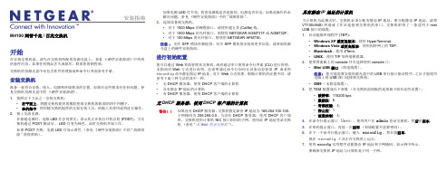
安装指南如果电源 LED 灯不亮,检查电源线是否连接好,电源是否有电。
如果此操作仍未解决问题,参见《硬件安装指南》中的“故障排除”。
3. 连接设备到交换机。
•对于 1000 Mbps 的铜缆接口,请使用超五类(Cat5e)线。
•对于 1000 Mbps 的光纤接口,则使用 NETGEAR AGM731F 或 AGM732F。
•对于 100 Mbps 的光纤接口,则使用 NETGEAR AFM735。
注意:光纤 SFP 模块单独提供。
有关SFP模块的安装的更多信息,请参阅资源光盘上的硬件安装指南。
进行初始配置您可以通过 Web 界面管理本交换机,或者通过串口使用命令行界面 (CLI) 进行管理。
本指南对 Web 方式进行说明。
也说明通过命令行如何让设备动态获取IP或者用ezconfig命令静态指定 IP 地址。
对于 Web 方式管理,根据计算机的设置不同,请参考下面三种方法的其中一种。
•无 DHCP 服务器,使用 DHCP 客户端的计算机•具有静态 IP 地址的计算机•有 DHCP 服务器,使用 DHCP 客户端的计算机无 DHCP 服务器,使用 DHCP 客户端的计算机警告!!如果没有 DHCP 服务器,交换机假定缺省 IP 地址为 169.254.100.100,子网掩码为 255.255.0.0。
当没有 DHCP 服务器,使用 DHCP 客户端时,交换机使用计算机 NIC 接口相同的子网。
使用此 IP 地址登录交换机(参见“从 Web 登录交换机”)。
具有静态 IP 地址的计算机当计算机为此模式时,交换机必须分配有静态 IP 地址。
要分配静态 IP 地址,请将VT100/ANSI 终端或工作站连接到交换机的串口。
交换机附带了一条适用于 miniUSB 接口的线缆。
1. 启动超级终端程序 (TEP):•Windows XP 或更低版本。
使用 HyperTerminal。
•Windows Vista 或更高版本。
NETGEAR 24-端口Gigabit智能管理加强型交换机(PoE+190W)说明书

Installation Guide 1. Register the switch1. From a computer or mobile device that is connected to the Internet, visit.2. Log in to your NETGEAR account.Note: If you don’t have a free NETGEAR account, you can create one.The My Products page displays.3. From the menu on the left, select Register a Product.4. In the Serial Number field, type the serial number of your switch.The serial number is 13 digits long. It is printed on the switch label.5. From the Date of Purchase menu, select the date that you purchased theswitch.6. Click the REGISTER button.Your switch is registered to your NETGEAR account.A confirmation email is sent to your NETGEAR account email address.April 2021© NETGEAR, Inc., NETGEAR and the NETGEAR Logoare trademarks of NETGEAR, Inc. Any non‑NETGEARtrademarks are used for reference purposes only.Continued on the next page. 24-port Gigabit Ethernet Smart Managed PlusSwitch with PoE+ (190W)Model GS324EPPackage contents• NETGEAR Gigabit Ethernet Smart Managed Plus Switch• Power cord (varies by region)• Rack‑mount installation kit• Rubber feet• Installation guideNote: We recommend that you use a Category 5e (Cat 5e) cable or higher-ratedcable for Gigabit Ethernet connections.2. Connect the switchSample connectionsTo use the SFP port, you must insert an SFP transceiver module, which you canpurchase from NETGEAR.This switch is designed for indoor use only. If you want to connect it to a devicelocated outdoors, the outdoor device must be properly grounded and surgeprotected, and you must install an Ethernet surge protector inline between theswitch and the outdoor device. Failure to do so can damage the switch.WARNING: Before connecting this switch to outdoor cables or devices, seehttps:///000057103 for safety and warranty information.3. Check the LEDsWhen you connect the power cord to the switch and plug it into an electricaloutlet, the LEDs indicate the status:LED DescriptionPower LED Solid green: The switch is powered on and operating normally.Off.Power is not supplied to the switch.Fan LED Solid green: The internal fan is operating normally.Solid amber.The internal fan failed.PoE Max LED(The status ofthe switch’s PoEbudget.)Off: Sufficient (more than 7W of) PoE power is available.Solid amber: Less than 7W of PoE power is available.Blinking amber: At least once during the previous two minutes, lessthan 7W of PoE power was available.Speed andactivity port LED(Upper portLED)Solid green:1000 Mbps link on the port.Blinking green: 1000 Mbps activity on the port.Solid amber: 100 Mbps or 10 Mbps link on the port.Blinking amber: 100 Mbps or 10 Mbps activity on the port.Off. No link is detected on the port.PoE port LED(Lower portLED)Solid Green: The port is delivering PoE power.Off: The port is not delivering PoE power.Solid amber: A PoE fault occurred on the port.4. Discover and access the switchThe NETGEAR Switch Discovery Tool (NSDT) lets you discover the switch in yournetwork and access the local browser interface of the switch from a Mac or aWindows-based computer.To install the NSDT, discover the switch in your network, access the switch, anddiscover the switch IP address:1. To download the tool, visithttps:///support/product/netgear-switch-discovery-tool.aspx.Download the Windows, Mac, or Linux version.2. Temporarily disable the firewall, Internet security, antivirus programs, or all ofthese on the computer that you use to configure the switch.3. Unzip the NSDT files, and click or double-click the executable file (forexample, NDST-1.2.102.exe) to install the program on your computer.You might see the tool icon appear on your Mac dock or Windows desktop.4. Reenable the security services on your computer.5. Power on the switch.6. Connect your computer to the same network as the switch.7. Open the NSDT.The initial page displays a menu and a button.8. From the Choose a Connection menu, select the network for this switch.9. Click the Start Searching button.The NSDT displays the IP addresses of the switches that it discovers.10. Click the ADMIN PAGE button for the switch.The login page or login window of the local browser user interface (UI)opens.11. Enter the default password that is printed on the switch label.Note: All port LEDs are located together on the left of the front panel.InternetPoE+ connectionsNon‑PoE connectionsNETGEAR, Inc.350 East Plumeria Drive San Jose, CA 95134, USA NETGEAR INTERNATIONAL LTD Floor 1, Building 3University Technology Centre Curraheen Road, Cork,T12EF21, Ireland12. If prompted, enter a new admin password for the switch.The Switch Information page displays, and shows the IP address assigned to the switch.13. Save the password and IP address for future use.You can now configure and monitor your switch.PoE considerationsPoE power supplied by the switch is prioritized in ascending port order (from port 1 to port 24). The switch can supply a total of 190W across all active PoE+ ports.The following table shows the standard power ranges without overrides applied, calculated with the maximum cable length of 328 feet (100 meters). If a device receives insufficient PoE power from the switch, consider using a shorter cable.PoE troubleshootingHere are some tips for correcting PoE problems that might occur:• If the PoE Max LED is solid yellow, disconnect one or more PoE devices toprevent PoE oversubscription.• For each powered device (PD) that is connected to the switch, the associatedPoE LED on the switch lights solid green. If the PoE LED lights solid yellow, aPoE fault occurred and PoE halted because of one of the conditions listed inthe following table:PoE Fault Condition Possible SolutionA PoE‑related short circuit occurred on the port.The problem is mostlikely with the attachedPD. Check the conditionof the PD, or restart thePD by disconnecting andreconnecting the PD.The PoE power demand of the PD exceeded themaximum level that the switch permits. The maximumlevel is 15.4W for a PoE connection and 30W for aPoE+ connection.The PoE current on the port exceeded theclassification limit of the PD.The PoE voltage of the port is outside the range thatthe switch permits.Restart the switch to seeif the condition resolvesitself.Support and CommunityVisit /support to get your questions answered and access the latestdownloads.You can also check out our NETGEAR Community for helpful advice at.Regulatory and LegalSi ce produit est vendu au Canada, vous pouvez accéder à ce document enfrançais canadien à https:///support/download/.(If this product is sold in Canada, you can access this document in CanadianFrench at https:///support/download/.)For regulatory compliance information including the EU Declaration ofConformity, visit https:///about/regulatory/.See the regulatory compliance document before connecting the power supply.For NETGEAR’s Privacy Policy, visit https:///about/privacy-policy.By using this device, you are agreeing to NETGEAR’s Terms and Conditions athttps:///about/terms-and-conditions. If you do not agree, returnthe device to your place of purchase within your return period.Do not use this device outdoors. The PoE source is intended for intra buildingconnection only.Mount the switch in a rackYou can mount the switch in a standard 19-inch (48.26-centimeter) network equipment rack. Use the 19-inch rack-mount installation kit supplied with the switch.1. Attach a supplied mounting bracket to each side of the switch.2. Insert the supplied screws through each bracket and into the bracketmounting holes in the switch.3. Tighten the screws with a No. 2 Phillips screwdriver to secure each bracket.4. Align the mounting holes in the brackets with the holes in the rack, and insertthe supplied two pan-head screws with nylon washers through each bracket and into the rack.5. Tighten the screws with a No. 2 Phillips screwdriver to secure the mountingbrackets to the rack.DeviceClassCompatible PoEStandardClass Description Maximum PowerSupplied by theSwitchPower Deliveredto the Device0PoE and PoE+Default power (full)15.4W0.44W–13.00W 1PoE and PoE+Very low power 4.0W0.44W–3.84W2PoE and PoE+Low power7.0W 3.84W–6.49W3PoE and PoE+Mid power15.4W 6.49W–13.00W 4PoE+High power30.0W13.0W–25.5W。
ProSAFE 48端口Gigabit Network Switch用户操作手册说明书
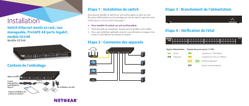
InstallationSwitch Ethernet monté en rack, non manageable, ProSAFE 48 ports Gigabit, modèle GS348Modèle GS348Etape 1 : Installation du switch Vous pouvez installer le switch sur une surface plane ou dans un rack. Pour plus d'informations sur le montage en rack du switch, reportez-vous à Montage en rack du switch à la page 2¾Pour installer le switch sur une surface plane :1. Fixez les pieds en caoutchouc fournis avec le produit sur le switch.2. Pour une ventilation optimale, assurez-vous de laisser un espace d'aumoins 5 centimètres tout autour du switch.Etape 2 : Connexion des appareilsContenu de l'emballageCordonrégion)Kit de fixation sur bâtiSwitch GS348Etape 3 : Branchement de l'alimentationEtape 4 : Vérification de l'étatVoyant d'alimentation Voyants des ports (ports 1 à 48) Activé Connexion à 1 000 Mbit/sDésactivéConnexion de 100 ou 10 Mbit/sActivité (clignotant)Pas de connexion (éteint)NETGEAR INTL LTDBuilding 3, University Technology Centre, Curraheen Road, Cork, IrlandeNETGEAR, Inc.350 East Plumeria DriveSan Jose, CA 95134, Etats-Unis© NETGEAR, Inc., NETGEAR et le logo NETGEAR sont des marquescommerciales de NETGEAR, Inc. Toutes les marques commerciales autresque NETGEAR sont utilisées à des fins de référence uniquement.Mars 2017Montage en rack du switchNous vous recommandons d'utiliser les équerres de fixation et les vis fournies avec le switch.1. A l'aide d'un tournevis cruciforme Philips n °2, fixez les équerres sur lescôtés du switch.a. Insérez les vis dans une équerre et dans les trous de montage duswitch.b. Serrez les vis pour fixer les équerres au switch.2. A l'aide d'un tournevis cruciforme Philips n °1, fixez les équerres dua. Alignez les trous de montage des équerres avec les trous du rack,puis insérez deux vis à tête cylindrique dans chaque équerre et dans le rack.b.Serrez les vis pour fixer les équerres au rack.SpécificationsAssistanceNous vous remercions pour l'achat de ce produit NETGEAR. Rendez-vous sur /support pour enregistrer votre produit, obtenir de l'aide, accéder aux téléchargements et manuels de l'utilisateur les plus récents et rejoindre notre communauté. Nous vous recommandons d'utiliser uniquement les ressources d'assistance officielles de NETGEAR.Pour consulter la déclaration de conformité actuelle pour l'UE, rendez-vous à l'adresse /app/answers/detail/a_id/11621.Pour obtenir les informations relatives à la conformité légale, visitez la page /about/regulatory/.Avant de brancher l'alimentation, reportez-vous au document de conformité légale.。
NETGEAR S350 Gigabit Smart Switch Series数据表说明书
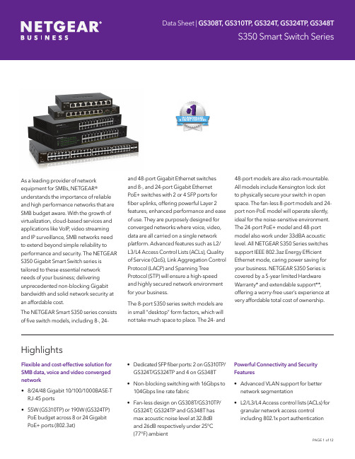
As a leading provider of network equipment for SMBs, NETGEAR® understands the importance of reliable and high performance networks that are SMB budget aware. With the growth of virtualization, cloud-based services and applications like VoIP, video streaming and IP surveillance, SMB networks need to extend beyond simple reliability to performance and security. The NETGEAR S350 Gigabit Smart Switch series is tailored to these essential network needs of your business; delivering unprecedented non-blocking Gigabit bandwidth and solid network security at an affordable cost.The NETGEAR Smart S350 series consists of five switch models, including 8-, 24- and 48-port Gigabit Ethernet switchesand 8-, and 24-port Gigabit EthernetPoE+ switches with 2 or 4 SFP ports forfiber uplinks, offering powerful Layer 2features, enhanced performance and easeof use. They are purposely designed forconverged networks where voice, video,data are all carried on a single networkplatform. Advanced features such as L2/L3/L4 Access Control Lists (ACLs), Qualityof Service (QoS), Link Aggregation ControlProtocol (LACP) and Spanning TreeProtocol (STP) will ensure a high-speedand highly secured network environmentfor your business.The 8-port S350 series switch models arein small “desktop” form factors, which willnot take much space to place. The 24- and48-port models are also rack-mountable.All models include Kensington lock slotto physically secure your switch in openspace. The fan-less 8-port models and 24-port non-PoE model will operate silently,ideal for the noise-sensitive environment.The 24-port PoE+ model and 48-portmodel also work under 33dBA acousticlevel. All NETGEAR S350 Series switchessupport IEEE 802.3az Energy EfficientEthernet mode, caring power saving foryour business. NETGEAR S350 Series iscovered by a 5-year limited HardwareWarranty* and extendable support**,offering a worry-free user’s experience atvery affordable total cost of ownership.HighlightsFlexible and cost-effective solution for SMB data, voice and video converged network• 8/24/48 Gigabit 10/100/1000BASE-T RJ-45 ports• 55W (GS310TP) or 190W (GS324TP) PoE budget across 8 or 24 Gigabit PoE+ ports (802.3at)• Dedicated SFP fiber ports: 2 on GS310TP/GS324T/GS324TP and 4 on GS348T• Non-blocking switching with 16Gbps to104Gbps line rate fabric• Fan-less design on GS308T/GS310TP/GS324T; GS324TP and GS348T hasmax acoustic noise level at 32.8dBand 26dB respectively under 25°C(77°F) ambientPowerful Connectivity and SecurityFeatures• Advanced VLAN support for betternetwork segmentation• L2/L3/L4 Access control lists (ACLs) forgranular network access controlincluding 802.1x port authenticationIN UNMANAGED & SMART SWITCHESNETGEAR quality and reliability • Industry-leading 5-year Limited Hardware Warranty*• Minimal down-time with Next- BusinessDay Replacement Warranty • Get 90-days Free Advanced Technical Support with device registrationPowerful Connectivity and Security Features (continued)• QoS (Quality of Service) for traffic prioritization including port-based, 802.1p and L2/L3/L4 DSCP-based • Auto “denial-of-service” (DoS)prevention• IGMP Snooping and Querier for multicast optimization• Rate limiting and priority queuing for better bandwidth allocation• Port mirroring for network monitoring • Energy Efficient Ethernet (IEEE 802.3az) for maximum power savings • Cable test to troubleshoot connection issues (except for GS324T/GS324TP)• Easy-to-use Web browser-basedmanagement GUI available in English, German and Japanese• SNMP v1, v2c, v3 and RMON remote monitoringSmart IT, not Big IT • Easy to manage via web-Based Management GUI or Smart Control Center (Windows PC required) formulti-switch deployment• Smart Control Center, a powerful tool for multi-switch discovery,deployment, monitoring and firmware upgrade • Network Management System (NMS300), allowing all NETGEARbusiness products to be deployed andmanaged through this single interface• Dual firmware images, improving reliability and uptime to your networkHighlightsHardware at a GlanceSoftware at a GlancePerformance at a GlanceHardware FeaturesDedicated SFP Fiber Uplinks Dedicated SFP ports provides fiber uplinks without sacrificing any downlink Gigabit port. Up to 4 SFP ports provide not only redundant uplinks, but can also build dual redundancy by a trunked uplink with link aggregation and failover, the dual- redundancy, a powerful design for the network virtualizationPoE+ Support on all ports (GS310TP and GS324TP)Flexible to plug-in or change into high-power PD devices on any port without worrying which one port to plug in and whether it will be running out of PoE+ ports.Low Acoustics Fan-less design on GS308T/GS310TP/GS324T, and maximum acoustic noise level at 32.8dB for GS324TP and 26dB for GS348T respectively at 25°C (77°F) ambient for quieter office environmentEnergy Efficient Ethernet (IEEE 802.3az)Maximum power reduction for ongoing operation cost savings. Software FeaturesAdvanced per port PoE controls Remote power management of PoE connected devices including operation sched-uling (e.g. Wireless APs, IP security cameras, secure access door locks, IoT devices…)ACL filtering to permit or deny traffic based on Provide granular network access control including L2/L3/L4 access control lists (ACLs).Robust security features:• 802.1x authentication (EAP)• Port-based security by locked MAC • DHCP Snooping Build a secured, converged network with all types of traffic by preventing external attacks and blocking malware, while allowing secure access for authorized users with RADIUS 802.1x port authentication.Comprehensive QoS features:• Port-based or 802.1p-based prioritization • Layer 3-based (DSCP) prioritization• Port-based ingress and egress rate limiting Advanced controls for optimized network performance and better delivery of mission-critical traffic such as voice and video.Auto-VoIP, Auto-Voice VLAN, and Auto-Video VLAN Automatic Voice over IP prioritization (Auto-VoIP) simplifies most complexmulti-vendor IP telephone deployments either based on protocols (SIP) or on OUI bytes (default database and user-based OUIs) in the phone source MAC address, providing the best class of service to VoIP streams (both data and signaling) over other ordinary traffic by classifying traffic, and enabling correct egress queue configuration. Similarly, Auto-Video VLAN enables IGMP snooping to minimize broadcast streams.IGMP Snooping Facilitate fast receiver joins and leaves for multicast streams. Save cost and improve network efficiency by ensuring multicast traffic only reaches designated receivers without the need of an extra multicast routerProtected Ports Ensure no exchange of unicast, broadcast, or multicast traffic between the protected ports on the switch, thereby improving the security of your converged network. This allows your sensitive phone conversations to stay private and your surveillance video clips can be forwarded to their designated storage device without leakage or alteration.DHCP Snooping Ensure IP address allocation integrity by only allowing DHCP messages from trusted DHCP servers and dropping malformed DHCP messages with a port or MAC address mismatch.Dynamic VLAN Assignment (RADIUS)IP phones and PCs can authenticate on the same port but under different VLAN assignment policies. Users are free to move around and enjoy the same level of network access regardless of their physical location on the network.Dual Firmware Images Dual firmware images for transparent firmware updates with minimum service interruption.Features and BenefitsWhy is the NETGEAR S350 Series Gigabit Ethernet Smart Switch the right choice for SMBs?As a leading provider of network equipment for SMBs, NETGEAR® understands the importance of reliable and high performance networks that are SMB budget aware. With the growth of virtualization, cloud-based services and applications like VoIP, video streaming and IP surveillance, SMB networks need to extend beyond simple reliability to performance and security. The NETGEAR S350 Gigabit Smart Switch series is tailored to these essential network needs of your business; delivering unprecedented non-blocking Gigabit bandwidth and solid network security at an affordable cost.What you can expect from NETGEAR S350 Series Switche s:• One-wire installation with 8, 12 or 24 Gigabit ports with PoE+ options (55W or 190W PoE total budget), and 2 or 4 SFP ports options provide not only redundant uplinks, but also build dual redundancy by a trunked uplink with link aggregation and failoverredundancy.• Quiet and Cost-effective Smart Layer2 switches with essential business class network needs, ideal for voice, video and dataconvergence in office application• Smart switch features include VLAN, ACL, QoS, IGMP Snooping, LACP Link aggregation, STP and SNMP for enhanced securityand reliability• Easy-to-use Web browser-based management GUI and full control through NETGEAR Smart Control Center, no need for an IT expert • 5-year hardware warranty with Next Business Day replacement, 90-day free technical supportExample ApplicationNetwork ConvergenceAccess PointsSecurity CamerasGS310TPInternetWiFi Router VoIP PhonesPCsFile Servers GS348TWireless Notebook PCsWiFi RouterMobile DevicesReadyNASLaptop ComputersT echnical Specifications GS308T GS310TP GS324T GS324TP GS348T 10M/100M/1G RJ-45 copper ports88242448PoE / PoE+ ports-8 PoE+ (55WPoE budget)-24 PoE+ (190WPoE budget)-1G SFP (fiber) ports- 2 (dedicated) 2 (dedicated) 2 (dedicated) 4 (dedicated) Performance SpecificationCPU500MHz128MB RAM32MB FLASH500MHz128MB RAM32MB FLASH800MHz512MB RAM128MB FLASH800MHz512MB RAM128MB FLASH400MHz512MB RAM128MB FLASHPacket buffer memory(Dynamically shared across only used ports)512KB512KB512KB512KB 1.5MB Forwarding modes Store-and-forwardBandwidth16 Gbps20 Gbps52 Gbps52 Gbps104 Gpbs Priority queues88448 Priority queuing Weighted Round Robin (WRR) and Strict PriorityMAC address database size(48-bit MAC addresses)8K8K16K16K16K Multicast groups256256512512512 Number of VLANs6464646464 Number of DHCP snooping bindings8K8K8K8K8K Access Control Lists (ACLs)100 shared for MAC (ingress)Packet forwarding rate(64 byte packet size) (Mpps) 11.914.838.638.677.3 Jumbo frame support (bytes)10K10K921692169216 Acoustic noise level @ 25°C (dBA) (ANSI-S10.12)Fan-less Fan-less Fan-less32.8dBA26.0dBAMean Time Between Failures (MTBF) @ 25°C2,957,592 hrs(337 yrs)1,081,119 hrs(123yrs)1,999,947 hrs(228 yrs)1,328,429 hrs(152 yrs)1,271,842 hrs(145 yrs)1G Copper Latency(64-byte; 1518-byte; 9216-byte frames)3.995µs;4.202µs;3.966µs3.995µs;4.202µs;3.966µs3.858μs;3.868μs;3.754μs3.734μs;3.749μs;3.807μs2.860μs;2.920μs;2.760μs1G Fiber Latency(64-byte; 1518-byte; 9216-byte frames)3.428µs;3.666µs;3.400µs2.899μs;2.937μs;2.860μs2.896μs;2.903μs;2.914μs1.740μs;1.720μs;1.680μsL2 Services - VLANsIEEE 802.1Q VLAN tagging YesIP-based VLANs YesMAC-based VLANs YesAuto-Voice VLAN Yes, based on OUI bytes (default database and user-based OUIs) in the phone sourceMAC addressAuto-VoIP Yes, based on protocols (SIP). Prioritzes traffic to a higher queueVoice VLAN Yes, based on either VLAN ID or 802.1p priority, packets are passed onto the connecting VoIPphone using LLDP-MED.Auto-Video VLAN YesL2 Services - Availability GS308T GS310TP GS324T GS324TP GS348T Broadcast, multicast, unknown unicast stormcontrol YesIEEE 802.3ad - LAGs (LACP)YesIEEE 802.3x (full duplex and flow control)YesIEEE 802.1D Spanning Tree Protocol YesIEEE 802.1w Rapid Spanning Tree Protocol YesIEEE 802.1s Multiple Spanning Tree Protocol YesL2 Services - Multicast FilteringIGMP snooping (v1, v2, and v3)YesIGMP snooping querier YesDHCP ServicesDHCP client YesDHCP snooping YesLink AggregationIEEE 802.3ad - LAGs (LACP)YesManual Static LAG Yes# of Static or LACP LAGs8 LAGs with max 8 members in each LAG# of Members in each LAGNetwork Monitoring and Discovery Services802.1ab LLDP YesSNMP v1, v2c, v3RMON group 1,2,3,9YesNetwork SecurityIEEE 802.1x YesGuest VLAN YesRADIUS-based VLAN assignment via .1x YesMAC-based .1x YesRADIUS accounting YesAccess Control Lists (ACLs)L2 / L3 / L4 ingressIP-based ACLs (IPv4 and IPv6)IPv4MAC-based ACLs YesTCP/UDP-based ACLs YesMAC lockdown YesMAC lockdown by the number of MACs YesControl MAC # Dynamic learned entries4096Control MAC # Static entries48IEEE 802.1x RADIUS port access authentication YesPort-based security by locked MAC addresses YesNetwork Security GS308T GS310TP GS324T GS324TP GS348T Broadcast, multicast, unknown unicast stormcontrol YesDoS attacks prevention YesQuality of Service (QoS)Port-based rate limiting Ingress andegress Ingress andegress Egress Egress EgressPort-based QoS YesDiffServ QoS YesIEEE 802.1p COS YesDestination MAC and IP YesIPv4 and v6 DSCP YesIPv4 and IPv6 T oS YesWeighted Round Robin (WRR)YesStrict priority queue technology YesAuto-VoIP VLAN / Auto-Voice VLAN Yes, based on OUI bytes (default database and user-based OUIs) in the phone source MAC address Auto-VoIP Yes, based on protocols SIP, H323 and SCCP. Prioritzes traffic to a higher queueVoice VLAN Yes, based on either VLAN ID or 802.1p priority, packets are passed onto the connecting VoIP phoneusing LLDP-MEDAuto-Video VLAN YesIEEE Network Protocols• IEEE 802.3 Ethernet• IEEE 802.3u 100BASE-T• IEEE 802.3ab 1000BASE-T• IEEE 802.3af PoE• IEEE 802.3at PoE+• IEEE 802.3az Energy Efficient Ethernet (EEE)• IEEE 802.3ad Dynamic Link Aggregation (LACP)• IEEE 802.3z Gigabit Ethernet 1000BASE-SX/LX • IEEE 802.3x Full-Duplex Flow Control• IEEE 802.1Q VLAN Tagging• IEEE 802.1AB LLDP with ANSI/TIA-1057 (LLDP-MED)• IEEE 802.1p Class of Service (CoS)• IEEE 802.1D Spanning Tree Protocol (STP)• IEEE 802.1s Multiple Spanning Tree (MSTP)• IEEE 802.1w Rapid Spanning Tree (RSTP)• IEEE 802.1x RADIUS Network Access ControlManagementPassword management YesConfigurable management VLAN YesAdmin access control via RADIUS and TACACS+YesSNTP client over UDP port 123YesSNMP v1/v2c YesSNMP v3 with multiple IP addresses YesRMON group 1,2,3,9YesPort mirroring Yes ingress and egressMany-to-one port mirroring 810262652 Web browser-based graphicaluser interface (GUI)YesManagement GS308T GS310TP GS324T GS324TP GS348T Smart Control Center (SCC) for multi-switchmanagement YesDual software (firmware) image YesCable test utility Yes Yes No No Yes TLS/HTTPS Web-based access (version)Yes (v1.2)File transfers (uploads, downloads)TFTP / HTTPHTTP upload/download (firmware)YesSyslog (RFC 3164)YesLEDsPer port Speed, Link/ActivitySpeed, Link/Activity, or PoEin differentmodeSpeed, Link/ActivitySpeed, Link/Activity, or PoEin differentmodeSpeed, Link/ActivityPer device Power Power, PoE Max Power Power, Fan, PoEMax Power, Fan Physical SpecificationsDimensions (W x D x H)158 x 101 x 30 mm(6.2 x 4.0 x 1.2 in)236 x 101 x 30 mm(9.3 x 4.0 x 1.2 in)328 x 169 x 43 mm(12.9 x 6.7 x 1.7 in)330 x 206 x 43 mm(13.0 x 8.1 x 1.7 in)440 x 206 x 43 mm(17.3 x 8.1 x 1.7 in)Weight 0.41kg(0.9 lb)0.61kg(1.34 lb)1.62kg(3.57 lb)2.69kg(5.93 lb)3.05 kg(6.72 lb)Power ConsumptionMax power (worst case, all ports used, full PoE,line-rate traffic) (Watts) 6.4W69.3W13.5W229.9W39.1W Max power without PoE (worst case, all portsused, line-rate traffic) (Watts)15.1W16.3WIddle power consumption (all ports link-downstandby) (Watts) 2.0W 3.3W 6.5W11.1W25.0WHeat Dissipation (worst case, all ports used, full PoE, line-rate traffic) (BTU/hr)Max:22.02 BTU/hrMax:236.59 BTU/hrMax:46.09 BTU/hrMax:784.88 BTU/hrMax:148.24 BTU/hrEnergy Efficient Ethernet (EEE) IEEE 802.3az Yes (deactivated by default)Fan Fan-less Fan-less Fan-less21 Environmental SpecificationsOperatingOperating temperature 0° to 40° C (32° to 104° F)0° to 45° C (32° to 113° F) Humidity (relative)95% maximum relative humidity (RH), non-condensingAltitude10,000 ft (3,000 m) maximumStorageStorage temperature –20° to 70°C (– 4° to 158°F)Humidity (relative)95% maximum relative humidity (RH), non-condensingAltitude10,000 ft (3,000 m) maximumElectromagnetic Emissions and Immunity GS308T GS310TP GS324T GS324TP GS348TCertifications CE: EN 55032:2012+AC:2013/CISPR 32:2012, EN 610003-2:2014, Class B, EN 61000-3-3:2013, EN 55024:2010VCCI: VCCI-CISPR 32:2016, Class ARCM: AS/NZS CISPR 32:2013 Class ACCC: GB4943.1-2011; YD/T993-1998; GB/T9254-2008 (Class A)FCC: 47 CFR FCC Part 15, Class A, ANSI C63.4:2014ISED: ICES-003:2016 Issue 6, Class A, ANSI C63.4:2014BSMI: CNS 13438 Class ASafetyCertifications CB report / certificate IEC 60950-1:2005 (ed.2) + A1:2009 + A2:2013UL listed (UL 1950)/cUL IEC 950/EN 60950CE LVD: EN 60950-1:2006 + A11:2009 + A1:2010 + A12:2011 + A2:2013RCM (AS/NZS) 60950.1:2015CCC (China Compulsory Certificate): GB4943.1-2011; YD/T993-1998; GB/T9254-2008 (Class A) BSMI: CNS 14336-1Warranty and SupportHardware Limited Warranty 5 years (switch)2 years(power adapter)5 years (switch)2 years(power adapter)5 years 5 years 5 yearsT echnical support via phone90 days free from date of purchase* Next-Business-Day (NBD) Replacement 5 yearsProSUPPORT OnCall 24x7 Service Packs**OnCall 24x7 extends the 90-day phone and email warranty entitled technical support for standard and advanced features to the length of the contract term.Category S1:PMB0S11-10000SPMB0S31-10000SPMB0S51-10000SCategory S2:PMB0S12-10000SPMB0S32-10000SPMB0S52-10000SCategory S2:PMB0S12-10000SPMB0S32-10000SPMB0S52-10000SCategory 1:PMB0311-10000SPMB0331-10000SPMB0351-10000SCategory 1:PMB0311-10000SPMB0331-10000SPMB0351-10000SPackage ContentsSmart SwitchüüüüüPower AdapterüüPower Cord (localized to region of sale)üüüüüRackmount KitüüüRubber footpads for tabletop installationüüüüüInstallation GuideüüüüüOrdering InformationGS308T-100NAS North America, Latin AmericaGS308T-100PES EuropeGS308T-100UKS United KingdomGS308T-100AUS Asia PacificGS308T-100JPS JapanGS308T-100INS IndiaGS308T-100PRS ChinaGS310TP-100NAS North America, Latin AmericaGS310TP-100EUS EuropeGS310TP-100AJS Asia PacificGS310TP-100INS IndiaGS310TP-100PRS ChinaGS324T-100NAS North America, Latin AmericaGS324T-100EUS EuropeGS324T-100AJS Asia PacificGS324T-100INS IndiaGS324T-100PRS ChinaGS324TP-100NAS North America, Latin AmericaGS324TP-100EUS EuropeGS324TP-100AJS APACGS324TP-100INS IndiaGS324TP-100PRS ChinaGS348T-100NAS North America, Latin AmericaGS348T-100EUS EuropeGS348T-100AJS APACGS348T-100INS IndiaGS348T-100PRS ChinaOptional Modules and AccessoriesAGM731F SFP Transceiver 1000BASE-SX (Short range, multimode)AGM732F SFP Transceiver 1000BASE-LX (Long range, single mode)AGM734-10000S SFP Transceiver 1000BASE-T Copper RJ45 GBIC* This product comes with a limited warranty that is valid only if purchased from a NETGEAR authorized reseller, and covers unmodified hardware, fans and internal power supplies – not software or external power supplies, and requires product registration at https:///business/registration within 90 days of purchase; see https://gear. com/about/warranty for details. Intended for indoor use only.** The NETGEAR OnCall 24x7 contract provides unlimited phone and email technical support for your networking product. For ProSAFE products purchased prior to 06/2014, also includes next business-day hardware replacement.† NETGEAR #1 in US Market Share according to NPD data for Unmanaged and Smart Switches, September 2019. NETGEAR #1 in Europe Market Share according to Context data for Unmanaged and Smart Switches, September 2019.NETGEAR and the NETGEAR Logo are trademarks of NETGEAR, Inc. in the United States and/or other countries. Other brand names mentioned herein are for identification purposes only and may be trademarks of their respective holder(s).NETGEAR,Inc.350E.PlumeriaDrive,SanJose,CA95134-1911USA,1-888-NETGEAR(638-4327),E-mail:****************,DS- GS308T/GS310TP/GS324T/GS324TP/GS348T-28Sept22。
NETGEAR XS712T 10G 8-Port Managed Switch 说明书
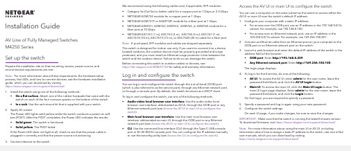
• NETGEAR AGM734 module for a copper port at 1 Gbps.
• NETGEAR AGM731F or AGM732F module for a fiber port at 1 Gbps.
• NETGEAR AXM761, AXM762, AXM763, AXM764, or AXM765 module for a fiber port at 10 Gbps.
1. Install the switch using one of the following methods: • On a flat surface. Attach one of the rubber footpads that came with the switch on each of the four concave spaces on the bottom of the switch. • In a rack. Use the rack-mount kit that is supplied with your switch.
Note: For more information about using the main UI or AV UI, including information about how to assign a static IP address to the switch, see one of the user manuals, which you can download by visiting https:///support/download/.
netgear+gs110tp+switch+用户手册说明书
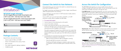
InstallationConnect the Switch to Your Network During initial setup, you must connect the switch to a network that you can access with a local WiFi connection.For Gigabit connections, use Category 5e (Cat 5e) or higher-rated Ethernet cables terminated with RJ-45 connectors.To use an SFP port, you must insert a 1G SFP transceiver module, which is available from NETGEAR.To use an SFP+ port, you must insert either a 10G SFP+ or 1G SFP transceiver module, which is available from NETGEAR. ¾To connect the switch:1. Connect devices to the network ports on the switch.2. Connect the switch a network.3. Power on the switch and wait for two or three minutes.The Power LED lights green, indicating that switch completed its startup process and is available on the network.The switch receives an IP address from a DHCP server (or a router that functions as a DHCP server) in your network. If your network does not include a DHCP server, the switch uses 192.168.0.239 as its default IP address.4. To check the port connections from the switch to the powered-ondevices that you connected, do the following:• Make sure that the Ethernet cables are plugged in correctly.• Check the left LED for each port on the switch.The left port LED lights solid green to indicate a valid connection to a powered-on device and blinks green to indicate traffic on this port.Package ContentsUnpack the box and verify the contents:• Switch model GC728X or GC728XP • Power cord (localized to the country of sale)• Rack-mount kit• Four rubber footpads for tabletop installation •Installation guideGC728XPGC728XAccess the Switch for ConfigurationThe NETGEAR Insight app lets you use your mobile device to discover,configure, manage, and monitor your switch. You can use this app to access the switch with a local WiFi connection or through the cloud.Local WiFi access . During initial configuration, you must use this method. The switch must be connected to a WiFi access point (because the switch does not provide WiFi capacity). Connect your mobile device to that access point’s WiFi network.Cloud access . After initial configuration, as long as your switch is on a network with an Internet connection, you can access the switch through the cloud. Note: You can also access the switch’s local browser–based management interface using a computer and a web browser. For more information, visit /support/product/GC728X and search for Configure the switchusing a web browser.NETGEAR Insight Managed28-Port Gigabit Ethernet Smart Cloud Switch with 2 SFP 1G & 2 SFP+ 10G Fiber Ports (GC728X)28-Port Gigabit Ethernet PoE+ Smart Cloud Switch with 2 SFP 1G & 2 SFP+ 10G Fiber Ports (GC728XP)InternetInternetInsightDecember 2017© NETGEAR, Inc., NETGEAR and the NETGEAR Logo are trademarks of NETGEAR, Inc. Any non‑NETGEAR trademarks are used for reference purposes only.NETGEAR, Inc.350 East Plumeria DriveSan Jose, CA 95134, USANETGEAR INTL LTDBuilding 3, University Technology Centre Curraheen Road, Cork, IrelandNote: You might be prompted to connect the switch to power and to an uplink. Since you already did this (see Connect the Switch to Your Network ), tap the NEXT button.The NETGEAR Insight app discovers the switch and registers it on the network that you named in Step 6.If you are using the local WiFi access method and the app does not discover the switch, make sure that your mobile device and the switch are connected to the same WiFi network.9. Select the switch to configure and manage it.You can use the NETGEAR Insight app to access the switch later to view or change the configuration settings.For more information on how to connect a NETGEAR Insight managed switch to an existing network, visit https:///000044341.PoE Troubleshooting for Model GC728XPHere are some tips for correcting simple problems that might occur:• Make sure that the PoE Max LED is off. The switch provides a totalpower budget of 390 watts. If the PoE Max LED is solid amber, disconnect one or more powered devices (PDs) to prevent PoE oversubscription. Start by disconnecting the PD from the highest-numbered port.Note: You can access the web management interface of the switch to manually override the amount of power that is reserved for each PoE port and attached PD.• Check the right LED for the port on the switch that is connected toa powered PD. The right port LED on the switch lights solid green to indicate that PoE is being delivered to the PD. If the right port LED lights solid amber, a PoE fault occurred. • For more information, see the user manual, which you can download byvisiting /support/product/GC728XP .Configure the Switch Using the NETGEAR Insight App¾To configure the switch:1. On your iOS or Android mobile device, visit the app store, search forNETGEAR Insight, and download the app.2. Connect your mobile device to the WiFi network of the access pointthat is connected to the switch.For initial configuration, you must use local WiFi access. After youcomplete initial configuration and discover the switch, you can use cloud access if the switch is connected to the Internet. 3. Open the NETGEAR Insight app on your mobile device.4. If you did not set up a NETGEAR account yet, tap CREATE NETGEARACCOUNT and follow the onscreen instructions.5. To log in to your NETGEAR account, tap LOG IN and enter yourcredentials.6. Name your network and specify a device admin password that appliesto all devices that you add to this network.7. Tap the NEXT button.8. To add the switch to your account, use one of the following options:• Enter the serial number.• Scan the serial number bar code.• Tap Switch as the device type and follow the prompts to scan thenetwork or scan the QR code.InsightSupportThank you for purchasing this NETGEAR product. You can visit/support to register your product, get help, access the latest downloads and user manuals, and join our community. We recommend that you use only official NETGEAR support resources.Si ce produit est vendu au Canada, vous pouvez accéder à ce document en français canadien à /other/.(If this product is sold in Canada, you can access this document in Canadian French at /other/.)For the current EU Declaration of Conformity, visit/app/answers/detail/a_id/11621/.For regulatory compliance information, visit /about/regulatory/.See the regulatory compliance document before providing power to the switch.Insight。
NETGEAR ProSafe Smart Switch XS712T - 安装指南说明书
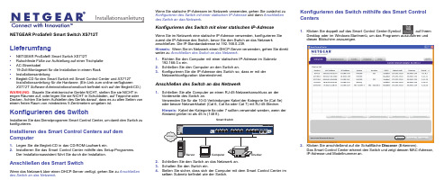
Installationsanleitung NETGEAR ProSafe® Smart Switch XS712TLieferumfang•NETGEAR ProSafe® Smart Switch XS712T•Rutschfeste Füße zur Aufstellung auf einer Tischplatte•AC-Stromkabel•19-Zoll-Montageset für die Installation in einem Rack •Installationsanleitung•Begleit-CD für den Smart Switch mit Smart Control Center und XS712T Installationsanleitung für die Hardware. (Ein Link zum online verfügbarenXS712T Software-Administrationshandbuch befindet sich auf der Begleit-CD.) WARNUNG:Stapeln Sie elektronische Geräte NICHT, stellen Sie sie NICHT in engen Räumen auf, oder legen Sie sie NICHT in Schubladen, auf Teppiche oder Decken. Achten Sie beim Aufstellen des Geräts darauf, dass es zu allen Seiten von einem freien Raum von mindestens 5 Zentimetern umgeben ist. Konfigurieren des SwitchInstallieren Sie das Dienstprogramm Smart Control Center, um damit den Switch zu konfigurieren.Installieren des Smart Control Centers auf dem Computer1.Legen Sie die Begleit-CD in das CD-ROM-Laufwerk ein.2.Installieren Sie das Smart Control Center mithilfe des Setup-Programms.Der Installationsassistent führt Sie durch die Installation.Anschließen des Smart SwitchWenn das Netzwerk über einen DHCP-Server verfügt, gehen Sie zu Anschließen des Switch an das Netzwerk.Wenn Sie statische IP-Adressen im Netzwerk verwenden, gehen Sie zunächst zuKonfigurieren des Switch mit einer statischen IP-Adresse und dann Anschließendes Switch an das Netzwerk.Konfigurieren des Switch mit einer statischen IP-AdresseWenn Sie im Netzwerk eine statische IP-Adresse verwenden, konfigurieren Siezuerst die IP-Adresse des Switch, bevor Sie den Switch an das Netzwerkanschließen. Die IP-Standardadresse ist 192.168.0.239.Hinweis:Wenn Sie im Netzwerk einen DHCP-Server verwenden, gehen Sie direktweiter zu Anschließen des Switch an das Netzwerk.1.Richten Sie den Computer mit einer statischen IP-Adresse im Subnetz192.168.0.x ein.2.Schließen Sie den Computer an den Switch an.3.Konfigurieren Sie die IP-Adresse des Switch so, dass er mit derNetzwerkkonfiguration übereinstimmt.Anschließen des Switch an das Netzwerk1.Schließen Sie alle Computer an einen RJ-45-Netzwerkanschluss an derVorderseite des Switch an.Verwenden Sie für die 10-G-Verbindungen Kabel der Kategorie 5e (Cat 5e)oder besser Netzwerkkabel (Cat 6, Cat 6a oder Cat 7) mit RJ-45-Stecker.Hinweis:Kabel der Kategorie 6a oder 7 sollten verwendet werden, wenn der2.Schließen Sie den Switch an das Netzwerk an.3.Schalten Sie den Switch ein.4.Stellen Sie sicher, dass sich der Computer mit dem Smart Control Center imselben Subnetz befindet wie der Switch.Konfigurieren des Switch mithilfe des Smart ControlCenters1.Klicken Sie doppelt auf das Smart Control Center-Symbol auf IhremDesktop oder im Windows-Startmenü, um das Programm auszuführen unddiesen Bildschirm anzuzeigen.2.Klicken Sie anschließend auf die Schaltfläche Discover (Erkennen).Das Smart Control Center erkennt den Switch und zeigt dessen MAC-Adresse,IP-Adresse und Modellnummer an.Janvier2013NETGEAR, das NETGEAR-Logo und Connect with Innovation sind Marken und/oder eingetragene Marken von NETGEAR, Inc. und/oder seiner Tochtergesellschaften in den USA und/oder anderen Ländern. Informationen können ohne vorherige Ankündigung geändert werden. © NETGEAR, Inc. Alle Rechte vorbehalten.In den Staaten der EU, EFTA und in der Schweiz nur für die Verwendung in Räumen vorgesehen.NETGEAR, Inc.350 East Plumeria Drive San Jose, CA 95134 USAWenn das Programm den Switch nicht erkennt, stellen Sie sicher, dass die Kabel richtig angeschlossen sind und dass sich die IP-Adresse des Computers im selben Subnetz befindet wie die des Switch. Klicken Sie dann erneut auf die Schaltfläche Discover (Erkennen).3.Klicken Sie auf die Leitung für den Switch, die konfiguriert werden soll.4.Klicken Sie auf Web Browser Access (Webbrowser-Zugriff), um denAnmeldebildschirm des Switch anzuzeigen.5.Geben Sie das Standardpasswort (password ) in Kleinbuchstaben ein, undklicken Sie auf Login (Anmelden).Der Bildschirm System Information (Systemdaten) wird angezeigt.6.Konfigurieren Sie den Switch für Ihr Netzwerk.Weitere Informationen finden Sie im XS712T Software-Administrationshandbuch .Tipps zur FehlerbehebungHier finden Sie Tipps zur Behebung einfacherer Probleme.•Achten Sie stets darauf, Computer und Switch in der korrekten Reihenfolgeeinzuschalten:1. Schalten Sie den Switch ein, und warten Sie dann 2 Minuten.2. Schalten Sie den Computer ein, und schließen Sie ihn an den Switch an.•Überprüfen Sie, ob die Netzwerkkabel richtig angeschlossen sind.Für jeden eingeschalteten Computer, der an den Switch angeschlossen ist, beginnt die Anzeige-LED für den LAN-Portstatus zu leuchten.•Stellen Sie sicher, dass die Netzwerkeinstellungen des Computers korrekt sind.In den meisten Fällen sollten Computer so konfiguriert sein, dass die IP-Adresse über DHCP bezogen wird.Wenn in Ihrem Netzwerk statische IP-Adressen verwendet werden, sollten Sie sicherstellen, dass der Switch und der Computer mit gültigen IP-Adressen konfiguriert wurden. Weitere Informationen finden Sie im Software-Administrationshandbuch.SupportVielen Dank, dass Sie sich für ein Produkt von NETGEAR entschieden haben.Registrieren Sie Ihr Gerät nach der Installation unter https:// . Sie benötigen dazu die Seriennummer, die sich auf dem Etikett des Produkts befindet. Die Registrierung ist Voraussetzung für die Nutzung des telefonischen Supports von NETGEAR. NETGEAR empfiehlt die Registrierung des Produkts über die NETGEAR-Website. Produkt-Updates und Support im Internet erhalten Sie unter .NETGEAR empfiehlt, nur die offiziellen Support-Seiten von NETGEAR zu nutzen.Weitere Informationen zum Einrichten, Konfigurieren und Verwenden des Smart Switch finden Sie im Software-Administrationshandbuch . Das Handbuch finden Sie unter .Die vollständige EU-Konformitätserklärung finden Sie unter: /app/answers/detail/a_id/11621/.。
- 1、下载文档前请自行甄别文档内容的完整性,平台不提供额外的编辑、内容补充、找答案等附加服务。
- 2、"仅部分预览"的文档,不可在线预览部分如存在完整性等问题,可反馈申请退款(可完整预览的文档不适用该条件!)。
- 3、如文档侵犯您的权益,请联系客服反馈,我们会尽快为您处理(人工客服工作时间:9:00-18:30)。
netgear switch用法
Netgear交换机是一种用于在局域网络中连接多台设备的网络设备。
它通过将多个设备连接到同一个网络上,实现设备之间的通信和数据
传输。
Netgear交换机可以提供更高的网络速度和更好的网络性能,同时也可以提供更大的网络容量和更灵活的网络管理。
使用Netgear交换机的步骤通常包括以下几个方面:
1.连接设备:将需要连接的设备(比如电脑、打印机、服务器等)通过网线连接到Netgear交换机的端口上。
2.配置交换机:通过登录交换机管理页面或者使用相关的配置工具,对交换机进行配置,包括设置端口、VLAN、网速等参数。
3.测试连接:连接设备后,通过测试网络连接和数据传输,确保
网络正常运作。
除了基本的连接设备和配置交换机外,还可以根据需要对Netgear 交换机进行进一步的功能拓展,比如设置QoS(服务质量)、安全设置、远程管理等。
另外,Netgear交换机也可以用于构建大型企业网络、校
园网络等复杂网络环境,提供更多的网络管理和控制功能,满足不同网络需求。
