可编程控制器罗克韦尔RSLogix5000介绍
2024年度abplcrslogix5000基础

根据通信需求配置相应的通信 模块,实现数据交换和远程控 制。
对各模块进行参数设置和地址 分配,确保系统正常运行。
9
典型硬件配置案例
1
案例一
单机控制系统。配置单个处理器模块、电源模块 和适量的I/O模块,实现对单台设备的控制。
2
案例二
多机联网控制系统。配置多个处理器模块、通信 模块和I/O模块,通过通信网络实现多台设备之 间的协同控制。
和错误提示等。
通讯工具
提供实时调试工具,可以在线监 控PLC的状态和变量值,支持断 点设置、单步执行和变量强制赋
值等操作。
2024/2/2
调试工具
提供仿真器功能,可以在计算机 上模拟PLC的运行环境和程序执 行过程,方便用户进行程序测试 和验证。
仿真器
提供多种通讯工具,支持与PLC 进行通讯和数据传输,包括串口 通讯、以太网通讯和USB通讯等 。
的安装程序。
安装过程
2024/2/2
运行安装程序,按照提示完成软件的 安装过程。可能需要输入序列号或激
活码以激活软件。
系统要求检查
确保计算机满足最低系统要求,包括 操作系统版本、处理器速度、内存和 可用硬盘空间等。
更新与补丁
安装完成后,检查是否有可用的更新 或补丁,以确保软件的最新版本和安 全性。
12
据共享。
无线连接
03
通过无线通信技术(如Wi-Fi、蓝牙等)连接设备,适用于移动
或难以布线的场合。
27
数据传输与共享
2024/2/2
数据传输方式
支持单向传输和双向传输,可根据需求选择合适的传输方式。
数据共享方式
支持多设备间的数据共享和交换,可实现设备间的协同工作和数据 整合。
AB_RSLogix5000初级使用手册
AB_RSLogix5000初级使用手册自从20世纪50年代开始,计算机技术便开始应用于工业自动化,既提高了生产效率,又降低了劳动强度,延长了工人寿命。
要实现高效率、高质量的生产,需要工业控制系统。
AB_RSLogix5000是一款广泛应用于工控领域的PLC( Programmable Logic Controller)编程工具软件,由美国ROCKWELL自动化公司研发,已经是最为成熟和广泛使用的PLC开发软件之一。
现在,随着科技创新的不断推进,越来越多的人开始学习AB_RSLogix5000的初级使用。
一、环境设置在进行AB_RSLogix5000的编程之前,我们需要对编程环境进行配置。
先安装AB_RSLogix5000编程软件,然后把PLC系统和PC通过以太网连接。
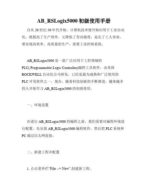
二、新建工程并配置1. 点击菜单栏“File --> New”,创建新工程。
2.选择相应的控制器,勾选相应的模块和设备,完成PLC的配置。
三、程序编写AB_RSLogix5000程序的编写采用基本的Ladder图形式进行编程,分为输入模块、输出模块和中间逻辑三个部分。
1. 输入模块的编写输入模块通常由传感器、开关等设备组成,用户需要根据硬件实际情况设置。
比如,我们可以通过配置“DINT-用电参数”来检测电机电流、电压等信息。
2. 输出模块的编写输出模块是控制器对设备输出实际信号的模块,比如我们可以通过PLC来控制灯的亮灭,完成“0”、“1”的操作。
在输出信号的过程中,可设置延时、执行次数、触发方式等参数。
这样,就可以根据实际需求进行设备控制。
3. 中间逻辑的编写在输入信号和输出信号中,中间逻辑部分起到了中转作用。
中间逻辑的编写涉及到了函数和数据块的使用,比如运用“while”、“if”等常用语句,或者“Timer”计时器,还可以对数据块进行操作。
四、调试和下载当程序编写完成之后,需要对程序进行调试,也就是在编程软件中模拟相应的操作环境,检查程序的正确性和实用性。
rslogix5000软件介绍
一、 控制器项目的创建一个首次使用,或者Firmware刷新后,或内存丢失的控制器,是不能直接在线连接的,必须将项目下载到控制器。
一般的,先在离线状态下建立一个项目,进行组态和编程,然后下载到指定的控制器。
下面,首先学习创建一个项目的操作。
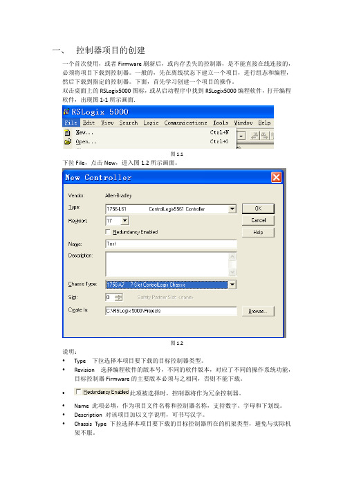
双击桌面上的RSLogix5000图标,或从启动程序中找到RSLogix5000编程软件,打开编程软件,出现图1‐1所示画面.图1.1下拉File,点击New,进入图1.2所示画面。
图1.2说明:y Type 下拉选择本项目要下载的目标控制器类型。
y Revision 选择编程软件的版本号,不同的软件版本,对应了不同的操作系统功能,目标控制器Firmware的主要版本必须与之相同,否则不能下载。
y此项被选择时,控制器将作为冗余控制器。
y Name 此项必填,作为项目文件名称和控制器名称,支持数字、字母和下划线。
y Description 对该项目加以文字说明,可书写汉字。
y Chassis Type 下拉选择本项目要下载的目标控制器所在的机架类型,避免与实际机架不服。
y Slot 指定本项目要下载的目标控制器在机架中所在槽的位置。
y Create In 指定本项目的磁盘存储文件在磁盘中的存放路径,默认值在C:\RSLogix 5000\Projects,亦可自行确定。
点击OK,进入如图1.3所示画面。
图1.3至此,一个项目被创建。
二、 本地I/O模块的建立和监控在I/O Configuration下,选中1756的背板,右击,选中New Module,出现下图所示画面。
1756机架可插放的模块在这里都能找到,亦可分类选择。
(1)数字量输入/输出模块的建立和监控数字量模块有8点、16点和32点之分,有交流和直流之分,有隔离和非隔离之分,模块用途各异,外端接线不同,不过组态过程是相似的。
点击New Module后,出现如下图所示画面。
由于要添加的是数字量模块,选择将Digital前的“+”展开,选择1756‐IB16D,这是一个16点24VDC输入模块带诊断功能,双击该模块,出现下图所示画面。
RSLogix5000培训教程

RSLogix5000培训教程RSLogix 5000是罗克韦尔自动化公司推出的一款基于Windows操作系统的集中式控制软件。
它广泛应用于工业自动化领域,许多工业企业都会在工作中使用这个软件。
因此,对RSLogix 5000软件进行培训教程将有助于工业人员更好地掌握和使用该软件,提高工作效率和质量。
首先,我们需要了解的是RSLogix 5000软件所用到的编程语言和基本概念。
RSLogix 5000支持几种编程语言,包括Ladder Diagram(梯形图)、Structured Text(结构化文本)、Function Block Diagram(功能块图)和Sequential Function Chart (序列功能图)。
每种编程语言都有它自己的语法和操作方式,根据实际应用需求选择相应的编程语言进行编程。
在使用RSLogix 5000软件时,我们需要了解基本概念,如标签、数据类型、Array(数组)、Tag UDT(用户定义的数据类型)等。
标签是一个变量的名称,可以定义为输入、输出或内部变量。
数据类型包括BOOL(布尔型)、INT(整型)、REAL (浮点型)等,其中BOOL是最常用的数据类型。
Array是由相同数据类型的元素组成的变量组合,其中每个元素都有相应的下标值。
Tag UDT是用户在程序中自定义的一个数据类型,可以包含不同的数据类型和结构体。
紧接着,我们需要了解的是如何创建一个工程和配置硬件设备。
在RSLogix 5000软件中,我们可以通过创建一个新工程来开始我们的编程工作。
在创建工程之前,我们需要选择相应的PLC类型、控制器和通信模块,并进行硬件配置。
这样,RSLogix 5000软件就可以连接到PLC并进行编程。
在完成硬件配置之后,我们可以配置主要的控制设备、输入和输出点等,这样可以保证我们的程序的准确性和稳定性。
在编写程序之前,我们还需要了解一些程序设计原则,如状态机、递归、中断服务程序等。
RSLogix5000培训教程
RSLogix5000培训教程RSLogix5000是一个广泛使用的自动化软件平台,可用于设计,实现,管理和监控各种工业自动化系统。
由于其高效性和易用性,RSLogix5000在现代制造业中占据着不可或缺的位置。
本文将介绍RSLogix5000培训教程,以帮助初学者快速入门。
1. 概述RSLogix5000软件是在RockwellAutomation公司掌握的Logix控制器系列硬件下的一款编程软件,提供了新一代的Tag 数数据和更强大的运算逻辑,能极大地提高编程效率。
其功能强大,适用范围广泛,应用于工业过程控制,自动化制造,建筑自动化,能源等领域。
2. RSLogix5000培训教程2.1 界面介绍RSLogix5000界面清晰,用户友好,并且提供了各种有用的工具和功能。
用户面板在左侧和顶部提供了更多操作选项和信息。
用户还可以在Configuration和Program等窗口中进行设置和操作。
2.2 创建新项目打开RSLogix5000软件,单击“File”菜单,在菜单中选择“New”创建新的项目。
在此窗口中,您可以选择硬件、控制、通信等选项来定制您的项目。
2.3 选择控制器类型选择控制器类型是创建新项目的第一步。
您可以从Controller Organizer树中选择控制器类型。
Controller Organizer 提供了多种常用的控制器类型,例如CompactLogix,ControlLogix等。
2.4 配置标签和I/O在创建新项目后,您需要配置您的标签和输入/输出设备(I/O)。
标签是您在编程中使用的变量名称,而I/O是您的控制器所需的输入和输出设备。
3. 编程概念编程概念是RSLogix5000培训教程的核心。
以下是一些基本概念。
3.1 程序程序是您在RSLogix5000中编写的代码。
程序是通过使用Instruction List(IL),Ladder Logic(LL),Structured Text(ST),Function Block Diagram(FBD)和Sequential Function Chart(SFC)等语言来编写的。
2024版rslogix5000软件培训ppt课件

2024/1/26
1
目 录
2024/1/26
• 软件介绍与安装 • 基本功能与操作 • 高级功能与特性 • 案例分析与实践操作 • 故障诊断与排除方法 • 总结回顾与拓展延伸
2
01
软件介绍与安装
2024/1/26
3
RSLogix5000软件概述
2024/1/26
生产线自动化改造效果评估与改进
介绍如何对生产线自动化改造的效果进行评估,以及如何进行持续改进和优化,提高生 产效率和产品质量。
21
05
故障诊断与排除方法
2024/1/26
22
常见故障类型及原因分析
软件崩溃或无法启动
可能是由于系统兼容性问题、软件bug或硬件故障等 原因导致。
程序无法下载或上传
可能是由于通信故障、硬件连接问题或程序错误等原 因导致。
2024/1/26
20
案例三:生产线自动化改造项目
生产线自动化改造需求分析
分析生产线自动化改造的需求和目标,确定改造的范围和重点。
RSLogix5000软件在生产线自动化改造中的应用
讲解如何使用RSLogix5000软件进行生产线自动化改造的规划和实施,包括设备选型、 控制系统设计、网络通信等。
2024/1/26
添加编程元素
从元素库中选择需要的编程元素,如 输入/输出模块、数据处理器、通信 接口等。
编辑编程元素
修改元素属性、设置参数、编写控制 逻辑等。
2024/1/26
元素间连接
通过连接线将不同元素连接起来,实 现数据交换和控制逻辑。
编程规范与技巧
遵循一定的编程规范,提高程序的可 读性和可维护性;掌握一些编程技巧, 提高编程效率和质量。
RSLogix5000部分培训资料

如何解决数据丢失或损坏的问题?
解决方法
尝试从最近的备份文件中恢复数据,或者联系技术支持 寻求帮助。
34
THANKS FOR WATCHING
感谢您的观看
2024/1/26
35
定时器/计数器指令
用于实现定时和计数功能,如TON( 接通延时定时器)、TOF(断开延时 定时器)等。
数据处理指令
用于数据的转换、移位、传送等操作 ,如MOV(传送指令)、SHL(左移 指令)、SHR(右移指令)等。
21
程序结构设计与优化建议
程序结构设计原则:遵循模块化、层 次化、清晰化的设计原则,提高程序
I/O模块选择
根据实际需求,选择合适的I/O模块类 型,如数字量、模拟量、特殊功能等 。
地址分配
配置参数
设置I/O模块的参数,如输入类型、输 出类型、滤波时间等,以满足实际应 用需求。
为每个I/O模块分配唯一的地址,确保 数据能够正确传输。
2024/1/26
17
网络通讯设置及优化
网络类型选择
根据实际需求,选择合适的网络类型 ,如EtherNet/IP、ControlNet、 DeviceNet等。
通讯参数设置
设置网络通讯的各项参数,如波特率 、数据位、停止位、校验位等,以确 保数据能够正确传输。
网络优化
针对网络通讯性能进行优化,如减少 网络负载、提高数据传输效率等。
故障诊断与排除
当网络通讯出现故障时,能够快速定 位并解决问题。
2024/1/26
18
CHAPTER 04
梯形图编程基础
2024/1/26
12
常用操作快捷键
粘贴
Ctrl+V
可编程控制器罗克韦尔RSLogix5000介绍
第二章RSLogix5000编程学习目标:■学会创建任务、程序、例程■深入理解标签、结构体和数组■掌握编写梯形图程序■学习I/O组态方法■掌握RSLogix5000功能块图编程122.1 编写RSLogix5000梯形图2.1.1 创建任务、程序和例程本次课程基于一个假想的工业环境。
您是一位压缩机装配项目程序开发人员。
图2-1描述了压缩机装配项目的整个工艺流程。
在该项目中,传送带上的压缩机经过三个装配站:冲压、卷边和焊接。
然后,压缩机被传送到第二个传送带并接受质量检查。
通过检查的压缩机码垛后装船运走。
图2-1 工艺流程图冲压、卷边和焊接三个装配站和传送带1由控制器P1控制,质量检查和码垛站以及传送带2由控制器P2控制。
图2-2给出了模拟各工作站运行时所用按钮和指示灯等离散量输入/输出点。
光眼检测到有部件放置到传送带上(PartSensor 由0变为1)后,站1、2和3顺序执行,然后传送带动作。
当光眼再次检测到有部件送至传送带上,上述操作再次执行,以此循环。
下面我们以时序图方式描述控制器P1的操作流程,如图2-3所示。
本实验主题:● 创建并组态一个控制器项目 ● 创建任务 ● 组态任务属性 ● 创建程序● 编辑程序排列表 ● 创建例程 ● 分配例程PartSensor 光眼检查码垛焊接卷边冲压3图2-2 各个按钮和指示灯的含义在了解了装配线工艺流程及控制器P1操作流程之后,您对项目主管说可以开始为控制器P1编程了,这让他感到很惊讶,因为以前都是在完成电气设计之后才能够编写控制程序。
在听过您的解释之后,他认为并行设计的方案是可行的。
同时,他也提醒你,如果该生产线效果良好,公司可能会再增加一条生产线,但控制器可能还是使用现有的ControlLogix 控制器,希望你在编程时考虑到这个问题。
Press 站工作中 StationActive光眼检测输入 PartSensorStake 站工作中 StationActiveWeld 站工作中StationActive光眼故障指示 Part_Sensor_Fault_Indicator传送带输出 ConveyorOutput(P1) 检查站工作中 StationActive码垛站工作中 StationActive检查通过 PartPASSED检查未通过 PartFAULT传送带输出ConveyorOutput(P2)光眼检测PartSensorPress站工作中StationActiveStake站工作中StationActiveWeld站工作中StationActive传送带输出ConveyorOutput(P1)图2-3 时序图实验步骤:1.双击桌面上图标,打开RSLogix5000软件,如图2-4所示。
Rslogix5000编程-快速入门

RsLogix5000编程-快速入门什么是RsLogix5000?RsLogix5000是一款由Rockwell Automation公司开发的自动化控制编程软件。
它是用于PLC(可编程逻辑控制器)的编程环境,可让用户编写和管理自动化系统的控制程序。
RsLogix5000的优点与其他PLC编程软件相比,RsLogix5000有以下优点:•强大而灵活的功能;•易于学习;•可以支持可视化提高编程效率;•可以根据用户的实际需求扩展功能。
RsLogix5000的应用场景RsLogix5000主要用于:•机器人控制;•系统集成自动化;•智能制造。
环境设置在开始使用RsLogix5000编程之前,需要确保计算机上已安装以下软件:•Windows 7或更高版本;•RsLogix5000版本12或更高版本。
编程步骤RsLogix5000的编程步骤如下:1.创建新项目2.创建路线3.配置模块4.编写程序5.下载程序创建新项目在RsLogix5000中,首先需要创建一个新项目作为主编程文件。
在创建新项目时,需要设置一个项目名称,选择PLC类型和CPU型号。
此外,用户还需要选择一个IO配置,在此过程中必须选择一种适合PLC的IO模块。
创建路线新项目创建后,用户需要创建一个路线。
路线是指PLC与其他组件之间的连接,如传感器和执行器。
路线的创建涉及到安装IO模块,根据实际情况进行物理布线并为每个模块分配一个地址。
配置模块与传统PLC编程不同,RsLogix5000不直接使用地址寻址。
相反,它使用标记(Tag)来代表硬件组件。
标记可以自定义,可以通过逻辑表达式引用,并且容易识别。
在配置PLC时,用户需要创建一个位置,以定义模块的输入和输出。
在创建位置时,用户需要指定每个位置的模块型号,并为每个位置分配一个任务。
任务是指PLC要执行的特定控制器逻辑,例如转发节点信号或控制执行器。
编写程序实际编写PLC程序的过程称为配置程序。
RSLogix5000软件初步介绍

12
帮助系统
帮助菜单包含下面的选择: • 有以下标题的内容:
– 内容 (按列表浏览) – 索引 – 查找 (搜寻词组或单词)
• 根据指令类型分组的指令帮助 • Release notes • PDF形式的在线手册
Confidential -- For Internal Use Only. Copyright © 2005 Rockwell Automation, Inc. All rights reserved.
重要:
不能够直接保存到软盘上.如果你这样做了,不管文 件多大,系统都会提示没有足够的空间。但我们可以 保存后,再把文件复制到软盘上
Confidential -- For Internal Use Only. Copyright © 2005 Rockwell Automation, Inc. All rights reserved.
9
工具栏
RSLogix 5000 软件包含很多工具栏, 它们都可以按照用户的 选择来移动或关闭:
标准工具栏
在线工具栏
路径工具栏
新部件工具栏 梯形图编辑工具栏
梯形图通用逻辑工具栏
书签工具栏
语言要素工具栏
Confidential -- For Internal Use Only. Copyright © 2005 Rockwell Automation, Inc. All rights reserved.
一个.l5k 工程文件 比 .acd 文件小得多
Confidential -- For Internal Use Only. Copyright © 2005 Rockwell Automation, Inc. All rights reserved.
一个快速讲解RSLogix5000仿真(中文)

RSLogix5000仿真快速讲解RSLogix Emulator 5000是一个软件模拟5000 Logix控制器的软件。
其目的是在没有硬件的情况下,模拟的真实功能PLC,. 并进行调试。
更多的信息可以参考LGEM5K-GR015A-EN-P AB出版。
As a quick introduction we’ll go through a simple example of setting up a simulation. 作为一个快速的介绍,我们通过过一个简单的例子建立的仿真。
三个主要步骤。
1.建立一个主机监控。
2.RSLinx.创建一个连接RSLinx。
3.构建一个项目相关的仿真硬件。
建立一个主机架点击开始> > > > RSLogixEmulate RSLogix5000 Chassis Monitor。
当仿真打开,只有一个空的机架。
一个RSLinx模块已经在0槽内。
在slot 1 可以根据模拟项目的需要来加入另一个RSLinx 模块来进入通讯扩展。
在这里我们搭建项目相关的硬件配置。
第一步将会增加CPU模块。
这是一个叫做Emulation Controller模块。
点击槽>创建模块。
1.选择模拟器RSLogix模仿5000控制器。
2.槽号选择23.点击加入4.在这一点上,你可能会出现一个讯息配置对话框。
配置默认值并单击“下一步”。
5.接下来的两个对话框设置,是控制器的细节。
点击“下一步”并完成对接受所有的默认值。
接下来我们将加入一些输入/输出的模块。
1.点击槽>创建模块。
2.选择1789 -SIM 32点输入/输出模拟器。
3.槽号选择3,然后点击OK。
4.A.接受缺省设置,点击下结束。
机架上将现在有两个仿真模块。
RSLinxRSLinx创建一个连接1.开始>程序下RSLinx > > >罗克韦尔软件RSLinx专业版2.点击Communications > 配置Configure Drivers.3.选择the Virtual Backplane (SoftLogix 58xx) driver现有的驱动类型列表。
RSLogix_5000介绍

Energy Storage Module Secure Digital non-volatile optional removable memory.
–
Memory configuration options
• • •
• Performance Overview (compared to L6x)
RS5K V6.00 FBD Language FlexLogix SoftLogix
RS5K V15.00 Phase Mngr/Batch Runtime I/O Addition Asian Languages Architect / Sys HW View
RS5K V17.00 Runtime Partial Import/Export Controller Change Logging FBD Adv Instructions GuardLogix SIL3 RSLA Library Mgmt Add PowerFlex Online RS5K V16.00 Concurrent Licensing Stratix Add-on Instruction RS5K Fuzzy Designer V19.50 FBD Usability Autosave/Recovery Firmware Supervisor Start Pages RS5K Kinematics V19.00 Drive Configure Delmia Integration RS5K V18.00
Enhanced SDRAM memory technology Onboard display providing enhanced controller diagnostics and runtime information USB 2.0 port replacing 9-Pin D-Shell RS232
罗克韦尔自动化 Logix 5000 控制系统参考手册说明书
Reference ManualOriginal InstructionsIntegrated ArchitectureLogix Control Systems Recommended Literature Controllers: Bulletin 1756, 1769, 5069Drives: Bulletin 20G, 20J, 2198I/O and Communication Modules: Bulletin 1715, 1756, 5069, 5094Graphic Terminals: Bulletin 2711P, 2713P, 2715PSoftware: Bulletin 9324Links to some of the most common manuals for products that are typically included in a Logix 5000™ control system. It also provides links to manuals that can help you:•Implement an EtherNet/IP network.•Develop a Logix controller-based safety system.•Use Studio 5000 Logix Designer® application to program your control system.•Use Studio 5000 View Designer® application to configure and program your operator interface.•Configure a motion solution.•Configure and use Rockwell Automation products to improve the security of your automation system. Topic PageSummary of Changes2Products Covered in this Publication2Logix 5000 Controllers Resources3Network and Communication Modules Resources4Instructions and Programming Resources4Security Resources5I/O Modules and Adapters Resources6Operator Interface Resources6Motion Resources7Drives Resources7Additional Resources92Rockwell Automation Publication IASIMP-RM001J-EN-P - September 2021Logix Control Systems Recommended Literature Reference ManualSummary of ChangesThis publication contains the following new or updated information. This list includes substantive updates only and is not intended to reflect all changes.Products Covered in this PublicationYou can find common manuals for these products in this publication.Controllers•1756 Series ControlLogix® Controllers, GuardLogix® Controllers, ControlLogix Redundancy Modules •5069 Series CompactLogix™ Controllers, Compact GuardLogix Controllers •1769 Series CompactLogix Controllers, Compact GuardLogix ControllersDrives•Kinetix® 5100, 5300, 5500, and 5700 Servo Drives •PowerFlex® 755T Drives with TotalFORCE® technologyStudio 5000 Design Environment•Studio 5000 Logix Designer® application •Studio 5000 View Designer® application •Studio 5000® Application Code ManagerI/O and Communication Modules•1756 ControlLogix I/O Modules and EtherNet/IP Communication Modules •Compact 5000™ I/O Modules and EtherNet/IP Communication Modules •FLEX 5000™ I/O Modules and EtherNet/IP Communication Modules •1715 Redundant I/O Modules •EtherNet/IP AdaptersOperator Interface•PanelView™ 5510 and PanelView 5310 Terminals•PanelView™ Plus 7 Standard and Performance TerminalsTopicPage Added ControlLogix 5580 Redundant Controllers User Manual to Logix 5000 Controllers resources 3Added Logix Designer Compare Tool User Manual to Programming resources 5Added CIP Security Proxy User Manual to Security resources5Added Studio 5000 View Designer software manuals to Operator Interface resources 6Added Kinetix 5300 Single-axis EtherNet/IP Servo Drives manuals to Drives resources7Added PowerFlex Drives with TotalFORCE Control Programming Manual - Firmware Revision 10 or later to Drives resources 7Added replacement guides to Drives resources7Logix Control Systems Recommended Literature Reference ManualOther Integrated Architecture System ProductsFor products not covered in this manual, go to the Technical Documentation Center at rok.auto/techdocs to browse documentation collections organized by product family. Or go to Literature Library at rok.auto/literature to search for documentation by catalog number, product name, or publication number.Logix 5000 Controllers ResourcesReference and task-based information to help you install, configure, and operate Logix controllers.Selection and Specifications•1756-SG001, ControlLogix System Selection Guide•1756-TD001, ControlLogix and GuardLogix Controllers Technical Data Specifications•1769-SG001, CompactLogix System Selection Guide•5069-TD002, CompactLogix and Compact GuardLogix Technical Data SpecificationsDesign Considerations•1756-RM094, Logix 5000™ Controllers Design Considerations Reference Manual•LOGIX-RM002, Estimated Logix 5000 Controller Instruction Execution Times Reference ManualManuals•ControlLogix and GuardLogix controllers user manuals-1756-UM543, ControlLogix® 5580 and GuardLogix 5580 Controllers User Manual-1756-UM015, ControlLogix 5580 Redundant Controllers User Manual-1756-UM022, GuardLogix 5570 Controllers User Manual-1756-UM001, ControlLogix System User Manual (for ControlLogix® 5570 and ControlLogix® 5560 controllers)-1756-UM535, ControlLogix 5570/5560 Redundancy User Manual•CompactLogix and Compact GuardLogix controllers user manuals-5069-UM002, CompactLogix 5480 User Manual-5069-UM001, CompactLogix 5380 and Compact GuardLogix 5380 Controllers User Manual-1769-UM021, CompactLogix 5370 Controllers User Manual-1769-UM022, Compact GuardLogix 5370 Controllers User Manual•Safety system reference manuals for GuardLogix and Compact GuardLogix controllers-1756-RM012, GuardLogix 5580 and Compact GuardLogix 5380 Controller Systems Safety Reference Manual-1756-RM099, GuardLogix 5570 and Compact GuardLogix 5370 Controller Systems Safety Reference Manual-1756-RM093, GuardLogix Controller Systems Safety Reference Manual (for GuardLogix 5570, GuardLogix 5560, and 1768 CompactGuardLogix Safety controllers using RSLogix 5000® version 20 and earlier)Rockwell Automation Publication IASIMP-RM001J-EN-P - September 20213Logix Control Systems Recommended Literature Reference ManualReplacement Guidelines•1756-RM100, Replacement Guidelines: Logix 5000 Controllers Reference ManualGuidelines for replacing the following:-ControlLogix 5560 or ControlLogix 5570 controller with a ControlLogix 5580 controller-GuardLogix 5560 or GuardLogix 5570 controller with a GuardLogix 5580 controller-CompactLogix5370L3controller to CompactLogix 5380 controllerNetwork and Communication Modules ResourcesReference and task-based information to help you design and implement an Ethernet network, and use EtherNet/IP communication modules in a Logix 5000 control system.Selection and Specifications•1756-TD003, 1756 ControlLogix Communication Modules SpecificationsDesign and Application Considerations•ENET-RM002, Ethernet Design Considerations Reference Manual•ENET-AT001, EtherNet/IP QuickConnect Application Technique•ENET-AT002, EtherNet/IP Socket Interface Application Technique•ENET-AT006, EtherNet/IP Parallel Redundancy Protocol Application Technique•ENET-AT007, EtherNet/IP Device Level Ring Application TechniqueManuals•ENET-UM006, EtherNet/IP Network Configuration User Manual-Overview of EtherNet/IP communication modules in Logix 5000 control systems; describes features and tasks that are common toEtherNet/IP network devices•ENET-UM004, ControlLogix EtherNet/IP Network Devices User Manual-Describes features and tasks that are specific to 1756 ControlLogix EtherNet/IP communication modules in Logix 5000 control systems •CNET-RM001, ControlNet to EtherNet/IP Migration Reference Manual-Provides information to migrate from an existing ControlNet® network to an EtherNet/IP™ networkInstructions and Programming ResourcesInformation to help you use Studio 5000 Logix Designer application to program your control system.Logix 5000 Controllers Instructions•1756-RM003, General Instructions Reference Manual•MOTION-RM002, Motion Instructions Reference Manual•1756-RM006, Advanced Process Control and Drives Instructions Reference Manual•1756-RM095, GuardLogix Safety Application Instruction Set Reference Manual•1756-RM087, Execution Time and Memory Use Reference Manual4Rockwell Automation Publication IASIMP-RM001J-EN-P - September 2021Logix Control Systems Recommended Literature Reference Manual Logix 5000 Controllers Common ProceduresThese manuals describe common procedures for programming and operating Logix 5000 controllers: 1756 ControlLogix, 1756 GuardLogix, 1769 CompactLogix, 1769 Compact GuardLogix, 5069 CompactLogix, and Studio 5000 Logix Emulate™.1756-PM001, Logix 5000 Controllers Common Procedures Programming Manual (provides links to the manuals in the following list)•1756-PM010, Add-On Instructions Programming Manual•1756-PM013, ASCII Strings Programming Manual•1756-PM020, Data Access Programming Manual•1756-PM002, EDS AOP Guidelines for Studio 5000 Logix Designer Programming Manual•1756-PM009, Function Block Diagram Programming Manual•1756-PM018, IEC 61131-3 Compliance Programming Manual•1756-PM019, Import/Export Project Components Programming Manual•1756-PM015, Information and Status Programming Manual•1756-PM004, I/O and Tag Data Programming Manual•1756-PM008, Ladder Diagram Programming Manual•1756-PM014, Major, Minor, and I/O Faults Programming Manual•1756-PM012, Messages Programming Manual•1756-PM017, Nonvolatile Memory Card Programming Manual•1756-PM011, Produced and Consumed Tags Programming Manual•1756-PM021, Program Parameters Programming Manual•1756-PM016, Security Programming Manual•1756-PM006, Sequential Function Charts Programming Manual•1756-PM007, Structured Text Programming Manual•1756-PM005, Tasks, Programs, and Routines Programming ManualProgramming Manuals•LOGIX-UM003, Studio 5000 Application Code Manager User Manual•LOGIX-UM006, Logix Designer and Library Object Manager User Manual•LDCT-UM001, Logix Designer Compare Tool User Manual•LOGIX-UM001, PhaseManager™ Software User Manual•1756-RM084, Import/Export Reference Manual•1756-RM085, Converting PLC-5® or SLC™ 500 Logic to Logix5550® Logic Reference ManualSecurity ResourcesResources to help you configure and use Rockwell Automation products to improve the security of your automation system.•SECURE-UM001, Security Configuration User Manual•SECURE-RM001, System Security Design Guidelines•SECURE-AT001, CIP Security™ with Rockwell Automation Products Application Technique•1783-UM013, CIP Security Proxy User ManualRockwell Automation Publication IASIMP-RM001J-EN-P - September 20215Logix Control Systems Recommended Literature Reference ManualI/O Modules and Adapters ResourcesReference and task-based information to help you install, configure, and operate I/O modules in a Logix 5000 control system. The products in this section are compatible with our newest controller platforms. To find manuals for other distributed I/O families, visit our Technical Documentation Center at rok.auto/techdocs.Selection and Specifications•1756-TD002, ControlLogix I/O Modules Technical Data Specifications•1715-TD001, 1715 Redundant I/O System Technical Data Specifications•5069-TD001, Compact 5000 I/O Modules and EtherNet/IP Adapters Technical Data Specifications•5094-TD001, FLEX 5000 I/O Modules Technical Data SpecificationsManuals•1756 ControlLogix I/O Modules-1756-UM058, ControlLogix Digital I/O Modules User Manual-1756-UM009, ControlLogix Analog I/O Modules User Manual•1715 Redundant I/O System-1715-UM001, 1715 Redundant I/O System User Manual•Compact5000I/O Modules-5069-UM007, Compact 5000 EtherNet/IP Adapters User Manual-5069-UM004, Compact 5000 Digital I/O Modules User Manual (includes standard and safety I/O)-5069-UM005, Compact 5000 Analog I/O Modules User Manual-5069-UM006, Compact 5000 Series High-speed Counter Modules User Manual-5069-UM003, Compact 5000 I/O Serial Module User Manual•FLEX 5000 I/O Modules-5094-UM005, FLEX 5000 EtherNet/IP Adapters User Manual-5094-UM001, FLEX 5000 Standard and Safety Digital I/O Modules User Manual-5094-UM002, FLEX 5000 Analog I/O Modules User Manual-5094-UM003, FLEX 5000 High-speed Counter Module User Manual-5094-UM007, FLEX 5000 Analog Isolated Current/Voltage/HART Input and Output ModulesOperator Interface ResourcesReference and task-based information to help you install, configure, and operate graphic terminals in a Logix 5000 control system. To find manuals for other PanelView products, visit our Technical Documentation Center at rok.auto/techdocs.Selection and Specifications•VIEW-SG001, Visualization Solutions Selection Guide•2715P-TD001, PanelView 5510 Terminals Technical Data Specifications•2713P-TD001, PanelView 5310 Terminals Technical Data Specifications•2711P-TD008, Bulletin 2711P PanelView Plus 7 Standard Terminals Technical Data Specifications•2711P-TD009, Bulletin 2711P PanelView Plus 7 Performance Terminals Technical Data Specifications6Rockwell Automation Publication IASIMP-RM001J-EN-P - September 2021Logix Control Systems Recommended Literature Reference ManualManuals•9343-GR001, Studio 5000 View Designer Getting Results Guide•9324-UM001, Studio 5000 View Designer User Manual•2715P-UM001, PanelView 5510 Terminals User Manual•2713P-UM001, PanelView 5310 Terminals User Manual•2711P-UM007, Bulletin 2711P PanelView Plus 7 Standard Terminals User Manual•2711P-UM008, Bulletin 2711P PanelView Plus 7 Performance Terminals User ManualMotion ResourcesReference and task-based information to help you configure and startup a motion solution.•MOTION-UM003, Integrated Motion on the EtherNet/IP Network Configuration and Startup User Manual•MOTION-RM003, Integrated Motion on the EtherNet/IP Network Reference Manual (AXIS_CIP_DRIVE attributes and integrated motion on the EtherNet/IP network control modes and methods)•MOTION-UM002, Motion Coordinate System User Manual•MOTION-AT005, Motion System Tuning Application Technique (tuning a Kinetix drive system)•IA-AT003, Integrated Architecture and CIP Sync™ Configuration Application Technique•MOTION-UM001, SERCOS and Analog Motion Configuration and Startup User ManualDrives ResourcesReference and task-based information to help you install, configure, and operate Allen-Bradley® Drives in a Logix 5000 control system. To find manuals for other Kinetix Servo Drive or PowerFlex Drive products, visit our Technical Documentation Center at rok.auto/techdocs.Selection and Specification•Kinetix EtherNet/IP Servo Drives-KNX-SG001, Kinetix Motion Control Selection Guide-KNX-TD003, Kinetix Servo Drives Specifications Technical Data-KNX-TD004, Kinetix Motion Accessories Specifications Technical Data•PowerFlex 755T AC Drives-PFLEX-SGOO2, PowerFlex Low Voltage Drive Selection Guide-750-TD100, PowerFlex 750-series Products with TotalFORCE Control Technical DataRockwell Automation Publication IASIMP-RM001J-EN-P - September 20217Logix Control Systems Recommended Literature Reference ManualManuals•Kinetix 5100 Single-axis EtherNet/IP Servo Drives-KNX-RM011, Kinetix 5100 Drive Systems Design Guide-2198-UM004, Kinetix 5100 Single-axis EtherNet/IP Servo Drives User Manual•Kinetix 5300 Single-axis EtherNet/IP Servo Drives-KNX-RM012, Kinetix 5300 Drive Systems Design Guide-2198-UM005, Kinetix 5300 Single-axis EtherNet/IP Servo Drives User Manual•Kinetix 5500 EtherNet/IP Servo Drives-KNX-RM009, Kinetix 5500 Drive System Design Guide-2198-UM001, Kinetix 5500 Servo Drives User Manual•Kinetix 5700 EtherNet/IP Servo Drives-KNX-RM010, Kinetix 5700 Drive Systems Design Guide-2198-UM002, Kinetix 5700 Servo Drives User Manual-2198-RM001, Kinetix 5700 Safe Monitor Functions Safety Reference Manual•PowerFlex 755T AC Drives-750-UM004, PowerFlex 755/755T Integrated Safety - Safe Torque Off Option Module User Manual-750-UM005, PowerFlex 755/755T Integrated Safety Functions Option Module User Manual-750-PM101, PowerFlex Drives with TotalFORCE Control Programming Manual - Firmware Revision 10 or later-750-PM100, PowerFlex Drives with TotalFORCE Control Programming Manual - Firmware Revision 6 or earlier-750-RM100, PowerFlex 750-Series Products with TotalFORCE Control Reference ManualReplacement Guidelines•Kinetix 5100 EtherNet/IP Servo Drives-2198-RM004, Kinetix 300 to Kinetix 5100 Servo Drives-2198-RM003, Ultra3000 to Kinetix 5100 Servo Drives•Kinetix 5300 EtherNet/IP Servo Drives-2198-RM005, Kinetix 350 to Kinetix 5300 Servo Drives-2198-RM006, Ultra3000 Digital Servo Drives to Kinetix 5300 Servo Drives•Kinetix 5500 EtherNet/IP Servo Drives-2093-AP001, Kinetix 2000 Multi-axis Servo Drives to Kinetix 5500 Servo Drives-2098-AP002, Ultra3000 Digital Servo Drives to Kinetix 5500 Servo Drives•Kinetix 5700 EtherNet/IP Servo Drives-2198-RM002, Kinetix 6000 Servo Drives to Kinetix 5700 Servo Drives•PowerFlex 755T AC Drives-750-RM003, PowerFlex 700AFE to PowerFlex 755TM Regenerative Bus Supply-750-RM004, PowerFlex 700S Phase II Drives to PowerFlex 755TL/TR Drives and PowerFlex 755TM Common Bus Inverters 8Rockwell Automation Publication IASIMP-RM001J-EN-P - September 2021Rockwell Automation Publication IASIMP-RM001J-EN-P - September 20219Logix Control Systems Recommended Literature Reference ManualAdditional ResourcesThese resources also provide helpful information for Logix 5000 control systems.You can view or download publications at rok.auto/literatureResourceDescriptionProduct Selection and Configuration website, rok.auto/systemtoolsProvides tools for product selection, control systems configuration, safety systems configuration, and power and motion systems.Sample Code Library, /global/sample-code/overview.page Share or download logic, HMI, and drives code.Industrial Components Preventive Maintenance, Enclosures, and Contact Ratings Specifications, publication IC-TD002Provides a quick reference tool for Allen-Bradley industrial automation controls and assemblies.Safety Guidelines for the Application, Installation, and Maintenance of Solid-State Control, publication SGI-1.1Designed to harmonize with NEMA Standards Publication No. ICS 1.1-1987 and provides general guidelines for the application, installation, and maintenance of solid-state control in the form of individual devices or packaged assemblies incorporating solid-state components.Industrial Automation Wiring and Grounding Guidelines, publication 1770-4.1Provides general guidelines for installing a Rockwell Automation industrial system.Product Certifications website, rok.auto/certifications .Provides declarations of conformity, certificates, and other certification details.Publication IASIMP-RM001J-EN-P - September 2021Supersedes Publication IASIMP-RM001I-EN-P - May 2020Copyright © 2021 Rockwell Automation, Inc. All rights reserved. Printed in the U.S.A.Rockwell Automation SupportUse these resources to access support information.Documentation FeedbackYour comments help us serve your documentation needs better. If you have any suggestions on how to improve our content, complete the form at rok.auto/docfeedback .Technical Support Center Find help with how-to videos, FAQs, chat, user forums, and product notification updates.rok.auto/support KnowledgebaseAccess Knowledgebase articles.rok.auto/knowledgebase Local Technical Support Phone Numbers Locate the telephone number for your country.rok.auto/phonesupport Technical Documentation Center Access technical documentation organized by product family.rok.auto/techdocs Literature LibrarySearch for installation instructions, manuals, brochures, and technical data publications.rok.auto/literature Product Compatibility and Download Center (PCDC)Get help determining how products interact, check features and capabilities, and find associated firmware.rok.auto/pcdcRockwell Automation maintains current product environmental certification information on its website at rok.auto/pec .Allen-Bradley, Compact 5000, CompactLogix, ControlLogix, expanding human possibility, FactoryTalk, FLEX 5000, GuardLogix, Integrated Architecture, Kinetix, Logix 5000, PanelView, PhaseManager, PLC-5, PowerFlex, Rockwell Automation, Rockwell Software, RSLogix 5000, SequenceManager, SLC, Studio 5000 Logix Designer, Studio 5000 Logix Emulate, Studio 5000 View Designer, and TotalFORCE are trademarks of Rockwell Automation, Inc.CIP Security, CIP Sync, ControlNet, DeviceNet, and EtherNet/IP are trademarks of ODVA, Inc.Trademarks not belonging to Rockwell Automation are property of their respective companies.Rockwell Otomasyon Ticaret A.Ş. Kar Plaza İş Merkezi E Blok Kat:6 34752, İçerenkÖy, İstanbul, Tel: +90 (216) 5698400 EEE YÖnetmeli ğine Uygundur。
RSLOGIX5000使用简介
10)要在 module 连接中断和不存在数据时在运行模式下产生严重故障, 请确保选定如果在运行模式下连接失败,则 Controller 将产生严重故障框。
11)单击确定,完成配置。
3.6创建Tag(标签/变量)
上面的步骤已经创建了新项目,现在使用预定义的 data type 为应用程序创建 tag。
首次创建项目时,RSLogix 5000 软件会为您创建连续的主 task。
1) 在 Controller 管理器中,双击 MainTask。
2) 在“名称”文本框中,输入描述主 task 的功能的名称。
3) 在“说明”文本框中,输入主 task 的说明。 4) 单击应用保存您所做的更改,但不关闭“属性”对话框。 5) 单击配置选项卡。 6) 从“类型”下拉列表中,选择应用程序所需的 task 类型
7) 要选择以其显示 tag 值的默认样式,请从下拉列表中 选择样式。
8) 单击确定。
9) 要编辑此 tag,双击 Program Tags 或 Controller Tags,取决于在其中创建 tag 的集合。
3.7输入梯形图Routine逻辑
通过在脱机的 routine 中输入梯形图元素开始编程项目。 1. 在 Controller 管理器中,双击要输入梯形图的 routine。 2. 要拖动工具栏中的指令,执行以下操作: A. 在“梯形元素”工具栏中,单击所需指令组的选项卡。
7. 要在指令周围回绕分支段,请将右侧的分 支段拖到指令另一侧的有效位置。 8. 要创建并行分支,右击现有分支左侧的分 支段,然后选择添加分支级别。
3.7输入梯形图Routine逻辑
rslogix5000仿真软件使用教程(2024)

与其他自动化系统集成方法
2024/1/27
OPC接口集成
rslogix5000支持OPC接口标准,可以与支持OPC接口的自 动化设备或软件进行数据交换和集成。
Modbus协议集成
通过Modbus协议,rslogix5000可以与支持Modbus协议 的设备进行通信和数据交换,实现与不同厂商设备的互联 互通。
24
自定义函数库创建及应用
自定义函数库创建
用户可以根据实际需求,创建自定义函数库,将常用的控制逻辑或算法封装成函数,方
便在多个项目中复用。
函数库管理
rslogix5000提供函数库管理功能,可以对自定义函数库进行添加、删除、修改等操作 ,实现函数库的灵活管理。
2024/1/27
函数调用与参数传递
在项目中可以直接调用自定义函数库中的函数,实现控制逻辑的快速搭建。同时,支持 函数参数的传递和修改,提高了函数的灵活性和可重用性。
3. 选择安装路径和组件,建 议保持默认设置。
2024/1/27
2. 双击安装程序,按照提示 进行安装。
4. 等待安装完成,期间可能 需要输入序列号和其他信息 。
5
授权与激活方法
在安装过程中,需要输入有效的序列号和授权信息。
如果已经安装但未激活,可以在软件界面中找到“帮助”或“激活”选项 ,按照提示进行激活操作。
23
数据监控与记录功能实现
实时数据监控
利用rslogix5000的数据监控功能,可以实 时查看和监控PLC内部的数据变化,包括寄 存器、变量、位状态等。
2024/1/27
历史数据记录
软件支持历史数据记录功能,可以记录PLC运行过 程中的关键数据变化,便于后续分析和故障排查。
2024年RSLogix5000培训教程
RSLogix5000培训教程一、引言RSLogix5000是美国罗克韦尔自动化公司推出的一款功能强大的可编程逻辑控制器(PLC)编程软件,广泛应用于工业自动化领域。
为了帮助用户更好地了解和使用RSLogix5000,本文将详细介绍RSLogix5000的基本概念、操作步骤和编程技巧,以便用户能够快速掌握并应用于实际工程中。
二、RSLogix5000基本概念1.1项目结构(1)控制器:表示一个PLC,可以添加多个控制器。
(2)程序:表示一个控制器的程序,包括程序文件和程序块。
(3)任务:表示程序中的一个执行单元,包括程序块和程序文件。
(4)程序块:表示程序中的一个功能模块,如程序、子程序、函数等。
(5)程序文件:表示程序中的一个文件,如梯形图、指令表、功能块图等。
1.2数据类型RSLogix5000提供了丰富的数据类型,以满足各种编程需求。
主要数据类型包括:(1)位数据类型:如BOOL、TE、WORD等。
(2)整数数据类型:如SINT、INT、DINT等。
(3)浮点数数据类型:如REAL、LREAL等。
(4)字符串数据类型:如STRING。
(5)时间数据类型:如TIMER、COUNTER等。
1.3I/O模块(1)离散输入/输出模块:如DI、DO。
(2)模拟输入/输出模块:如、AO。
(3)特殊模块:如温度、压力、流量等传感器模块。
三、RSLogix5000操作步骤2.1创建新项目(1)启动RSLogix5000软件。
(2)“新建”按钮,选择项目类型和控制器型号。
(3)输入项目名称和路径,“创建”按钮。
2.2配置I/O模块(1)在项目结构中,选择控制器,右键“添加I/O模块”。
(2)在I/O模块列表中,选择所需模块,“添加”按钮。
(3)配置模块参数,如通道、地质、数据类型等。
2.3编写程序(1)在项目结构中,选择程序,右键“添加程序块”。
(2)在程序块列表中,选择所需块类型,如程序、子程序、函数等。
ControlLogix5000系列大型PLC

ControlLogix5000 系列大型PLCControlLogix5000 系列大型可编程逻辑控制器(PLC)是由 Rockwell Automation 公司推出的一种工业自动化控制设备。
它基于先进的控制算法和现代化的硬件平台设计,可用于各种各样的应用场合,包括汽车制造、食品与饮料生产、半导体生产、化学合成等领域。
ControlLogix5000 系列 PLC 具有高性能、强大的控制功能、可扩展性强、易于维护等特点,已被广泛应用于全球各大工业自动化领域。
ControlLogix5000 PLC 设计特点ControlLogix5000 PLC 是一种基于冗余控制器架构的设备,它使用红外线技术来实现冗余控制器的同步交换。
PLC 内部的各个板卡采用了高速的以太网和 CAN总线技术来进行通信,以保证 PLC 的高性能和稳定性。
ControlLogix5000 PLC 支持快速的 PLC 项目生成,用户可以轻松创建和配置PLC 项目,以满足自己的应用需求。
PLC 项目开发采用了模块化设计,很大程度地简化了用户的开发工作。
另外,PLC 项目的生成工具还支持远程单元扩展,用户可以很方便地进行远程控制和监视。
ControlLogix5000 PLC 总线架构ControlLogix5000 PLC 采用了基于 ControlNet 或以太网总线协议的控制器架构。
其中,ControlNet 总线协议是一种高速、高可靠性、低延迟的控制总线,可以用于数据传输、远程输入/输出控制和可编程控制。
以太网总线协议则是一种多功能、高带宽、通用的数据通信协议,可以用于各种应用领域,如计算机网络、工业自动化、数据中心等。
ControlLogix5000 PLC 采用了基于以太网的在线控制实现,实现了 PLC 与上位机的高速报文交换。
PLC 通过 Ethernet/IP 协议与上位机通信,在实现数据交换的同时,保证了数据的实时性和稳定性。
罗克韦尔RSLOGIX5000的使用方法
罗克韦尔RSLOGIX 5000的使用方法摘要:通过示例项目讲解RSLOGIX 5000从项目的启动、实施到测试过程,深入浅出地软件的的编程方法关键词:PLC;软件;编程A description of ROCKWELL programming software RSLOGIX 5000 and its applicationAbstract:The programming method employing the ROCKWELL RSLOGIX 5000 software is briefly described with examples,including the start—up of an item,and execution and debugging of the item.1 引言RSLOGIX5000是美国AB公司开发的用于对其公司PLC产品编程的软件。
它具有以下特点:1.统一的项目查看2.灵活的梯形图编辑器3.拖放式操作4.梯形图查看选项5.定制数据监视6.状态文件分类显示7.简易的通讯配置8.强大的数据库编辑器9.查找与替换10.直观的windows界面11.项目校验快捷地更正程序错误等。
2 创建工程下面介绍如何使用RSLogix5000,首先要创建新的RSLogix5000工程文件。
具体步骤如下:打开RSLogix5000,见图1-1图1-1打开后的窗口为RSLogix5000的工程,见图1-2:首先你要给PLC的处理器定义,定义的内容有名字、类型、机架的背扳所在槽号、创建的文件路径等。
这里处理器类型选1756 L1 controllogix 5550,名字定为PLC,description定为练习,背板定为13槽,槽号0槽,路径默认。
图 1-2点击ok完成设置,显示RSLogix5000工程界面首先提出tag(标签)的概念,标签:就是实际工程中的变量,有模拟量如水位、压力、温度。
- 1、下载文档前请自行甄别文档内容的完整性,平台不提供额外的编辑、内容补充、找答案等附加服务。
- 2、"仅部分预览"的文档,不可在线预览部分如存在完整性等问题,可反馈申请退款(可完整预览的文档不适用该条件!)。
- 3、如文档侵犯您的权益,请联系客服反馈,我们会尽快为您处理(人工客服工作时间:9:00-18:30)。
第二章RSLogix5000编程学习目标:■学会创建任务、程序、例程■深入理解标签、结构体和数组■掌握编写梯形图程序■学习I/O组态方法■掌握RSLogix5000功能块图编程2.1 编写RSLogix5000梯形图2.1.1 创建任务、程序和例程本次课程基于一个假想的工业环境。
您是一位压缩机装配项目程序开发人员。
图2-1描述了压缩机装配项目的整个工艺流程。
在该项目中,传送带上的压缩机经过三个装配站:冲压、卷边和焊接。
然后,压缩机被传送到第二个传送带并接受质量检查。
通过检查的压缩机码垛后装船运走。
图2-1 工艺流程图冲压、卷边和焊接三个装配站和传送带1由控制器P1控制,质量检查和码垛站以及传送带2由控制器P2控制。
图2-2给出了模拟各工作站运行时所用按钮和指示灯等离散量输入/输出点。
光眼检测到有部件放置到传送带上(PartSensor 由0变为1)后,站1、2和3顺序执行,然后传送带动作。
当光眼再次检测到有部件送至传送带上,上述操作再次执行,以此循环。
下面我们以时序图方式描述控制器P1的操作流程,如图2-3所示。
PartSensor光眼 检查 码垛焊接 卷边 冲压本实验主题:●创建并组态一个控制器项目●创建任务●组态任务属性●创建程序●编辑程序排列表●创建例程●分配例程Press站工作中StationActive 光眼检测输入PartSensorStake站工作中StationActive Weld站工作中StationActive光眼故障指示Part_Sensor_Fault_Indicator传送带输出ConveyorOutput(P1)检查站工作中StationActive码垛站工作中StationActive检查通过PartPASSED检查未通过PartFAULT传送带输出ConveyorOutput(P2)图2-2 各个按钮和指示灯的含义在了解了装配线工艺流程及控制器P1操作流程之后,您对项目主管说可以开始为控制器P1编程了,这让他感到很惊讶,因为以前都是在完成电气设计之后才能够编写控制程序。
在听过您的解释之后,他认为并行设计的方案是可行的。
同时,他也提醒你,如果该生产线效果良好,公司可能会再增加一条生产线,但控制器可能还是使用现有的ControlLogix控制器,希望你在编程时考虑到这个问题。
光眼检测PartSensorPress站工作中StationActiveStake站工作中StationActiveWeld站工作中StationActive传送带输出ConveyorOutput(P1)图2-3 时序图实验步骤:1.双击桌面上图标,打开RSLogix5000软件,如图2-4所示。
单击New(新建)图2-4 RSLogix5000启动界面2.单击File->New创建新项目。
您会看到New Controller(新建控制器项目)界面。
起始槽号为0。
您可以直接观察ControlLogix Demo箱,确定Logix5555控制器所在槽位;也可以打开RSLinx软件,组态通讯,在RSWho中确定Logix5555控制器槽位,第二种方法显然更适用于操作员处于远程位置时。
配置好的画面如图2-5所示:图2-5 新建控制器对话框单击OK,弹出如图2-6所示画面。
缺省创建连续型任务图2-6 新建项目资源管理器现在我们已经创建了一个ControlLogix项目。
此时我们还没有添加任何与项目相关的I/O模块,项目中也没有可执行的代码(如梯形图)。
你正在离线工作,所作的任何改变都只限于软件中,并存储在计算机的硬盘中。
在进行在线操作前,这些变化并不能反映到Logix5555控制器中。
3.接下来,根据应用实例要求来组织控制器P1项目中任务、程序和例程及其操作要求。
控制器P1项目组织结构,如表2-1所示。
表2-1控制器P1项目组织操作要求:控制器P1中任务必须符合以下要求:●装配线任务(站1,2,3)--执行时间不超过500ms--根据调度连续运行●传送带任务--执行时间不超过500ms--与调度任务分时执行(两任务的优先级相同)--每50ms执行一次调度任务--执行时间不超过400ms--与传送带任务分时执行(两任务的优先级相同)--每50ms执行一次4.Logix控制器不仅支持Continuous(连续型)任务,还支持Periodic(周期型)和Event(事件型)任务。
根据上述P1的操作要求,确定控制器P1中各任务的属性,并记录到表2-2中。
表2-2 控制器P1中各任务的属性5.Logix控制器仅支持一个连续型任务,且RSLogix5000已经自动创建了连续型任务MainT ask(如图2-6所示)。
在MainT ask文件上单击右键,在弹出菜单中选择Properties (属性),将MainT ask任务名称改为Assembly,并输入相应属性值。
6.单击File->New component->T ask或在项目管理器Tasks(任务)文件夹上单击右键,在弹出菜单中选择New Task…创建新任务Conveyor,并设置相应属性,如图2-7所示,因为传送带任务要求50ms执行一次,所以选择Periodic(周期型)任务。
同理,创建新任务Periodic_Dispatcher,并设置相应属性,保存该项目。
图2-7 创建新任务Conveyor7.创建Assembly(装配线)任务的程序。
在Assembly文件夹上单击右键并在弹出菜单中选择New Program(创建新程序)。
输入程序名称Program_1_Press并设置相应属性,如图2-8所示。
同理创建Program_2_Stake,以及Program_3_Weld并设置相应属性。
图2-8创建新程序8.规划Assembly(装配线)任务的程序。
右键单击Assembly任务,从弹出的对话框中选择Properties(属性)。
从弹出属性对话框中选择Program Schedule(程序规划)选项卡。
规划后的程序如图2-9所示:图2-9规划程序9.为Assembly(装配线)任务的Program_1_Press程序创建例程。
右键单击Program_1_Press程序,在弹出菜单中选择New(新建),在弹出的对话框中输入名称Routine_Dispatch(调度例程),类型为Ladder Diagram(梯形图),作用域在Program_1_Press程序中,如图2-10所示。
该例程用于调度程序中其它的子例程。
图2-10 创建例程同理,创建Station_1_Press(冲压)例程,类型为Ladder Diagram(梯形图),范围在Program_1_Press程序中。
该例程用于控制冲压工序的时间。
10.为Assembly(装配线)任务中Program_1_Press程序指定主例程。
右键单击Program_1_Press程序,在弹出菜单中选择Properties(属性)。
在弹出的对话框中选择Configuration(组态)选项卡。
Assigned Main(指定主例程)为Routine_Dispatch(调度程序),如图2-11所示。
图2-11 指定主例程11.按照相同的步骤,用户可自行为Program_2_Stake、Program_3_Weld程序创建相应例程并设置主例程。
12.对于Conveyor和Periodic_Dispatcher任务,请按照图2-12所示执行如下操作:--创建所需程序;--创建所需例程并指定主例程。
图2-12 新建任务、程序和例程13.单击File->Save,保存该项目。
该项目所有任务、程序和例程创建完毕。
至此,您已完成创建任务、程序和例程的所有实验!2.1.2 创建标签、结构体和数组在本实验中,我们将结合应用实例继续前面的工作,创建相应的标签、结构体和数组。
Logix控制器的特点:无需手动进行I/O映射,根据控制属性,自动创建/命名标签,并且支持结构体和数组。
另外,控制器域和程序域标签分类提高了代码重用性。
本实验的主题:1.创建控制器域和程序域的标签2.创建用户自定义数据类型实验步骤:1.双击桌面上图标,打开RSLogix5000软件。
2.选择File->Open,选择上一实验所创建项目P1并打开。
3.右键单击Controller Tags(控制器标签),在弹出的菜单中选择New Tag…(新建标签)。
Tag Name类似于其它编程语言中的变量-它们均用于存储数值。
你可以根据P&ID(管道仪表图)或电气设计图中的符号名称来命名标签(T ag Name)。
您在此输入标签名称会保存在PLC中,不会因为更换用于编程的上位机而丢失。
且这些Tag Name 可供系统中的人机界面直接使用,而无须重新定义。
这都会为您的编程、文档管理和系统维护带来极大的便利。
在对话框中输入名称Call_Program_Value,数据类型INT,标签类型为Base(基本型),范围为P1(Controller),显示类型为Decimal(十进制),如图2-13所示。
图2-13 新建标签4.按照上述步骤逐个创建以下控制器域的标签,如图2-14所示,这些标签将在下一实验中用到。
图2-14 控制器域标签5.创建下面的Conveyor程序域内的标签,如图2-15所示。
图2-15 Conveyor程序域内标签6.创建下面的Station_Dispatcher(站调度)程序域的标签如图2-16所示。
图2-16 Station_Dispatcher程序域内标签7.创建下面的Program_1_Press(冲压站)程序域的标签,如图2-17所示。
图2-17 Program_1_Press程序域内标签8.将Program_1_Press(冲压站)程序域的标签复制(Ctrl+C)并粘贴(Ctrl+V)到Program_2_Stake和Program_3_Weld程序域内,无须重建标签,提高代码重用性。
在此我们注意到,在Logix控制器中,不同程序域内的标签名称是可以相同的。
9.创建用户自定义数据类型。
在控制器P1中为每个压缩机生成一个产品编号(Product ID),每个产品编号由零件编号(Part_ID)、序列号(Serial_No)和目录号(Catalog_No)三部分构成。
使用用户自定义数据结构可以更方便的管理这种数据类型的标签。
如图2-18所示,右键单击Data Type文件夹下User-Defined(用户自定义),在弹出的菜单中选择New Data Type…(新建数据类型)。
图2-18 新建用户自定义数据类型10.在弹出画面中输入自定义数据类型的Name(名称)和Members(成员),如图2-19所示。