LJD-10A打印式流速仪使用说明书
LC型容积式流量计使用说明书

容积式流量计使用说明书Shanghai Cixi Instrument Co. Ltd概 述LC 容积式流量计,系直读累积式液体流量计,LCB 型容积式流量计,是LC 型流量计的基础上增加了发讯机构,可与本厂产品《微机流量控制仪》配套,广泛用于管道中液体流量(总量)或瞬时流量的测量和自动控制。
由于它具有量程范围大,精度高,性能稳定,能测高温,高粘度液体,安装简易,操作方便等诸多优点,适用于石油开采、炼油、化工、商业、储油库等工业部门的流体计量。
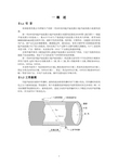
工作原理液体流量的计量是在测量室内完成的(见图1)。
在测量室内有一对椭圆齿轮,在进口和出口两端液体压差作用下,一对椭圆齿轮在转轴上不停地转动,测出其转数即可知道流经仪表液体的总量。
如图1(a )所示,一对椭圆齿轮A 、B 把进口与出口分开,在齿轮A 与计量室内壁形成一个新月形空间的液体称为“一份”(图上以阴影表示)。
齿轮A 有一转动矩,而齿轮B 上总力矩等于零。
齿轮A 带动齿轮B 转动。
图1(b )是两轮的中间位置,当移动到位置如图1(c )所示时,齿轮A 失去了转动力矩,而齿轮B 获得了转动力矩,齿轮B 带动齿轮A 转动,如图1(d )所示。
图1 工作原理图结 构LC 型容积式流量计主要由计量室、密封机构和计数机构组成。
1、计量室:仪表躯壳①(图2、图3、以下同)有铸铁制成,它的内腔与盖板④组成测量室。
测量室内有两根不锈钢轴②,一对椭圆齿轮③就套在轴上,靠流量计进出口处的压力差推动而旋转,从而不断地把进口处的液体经新月形空腔计量后送到出口处,每旋转一周,累计处四倍新月形空间的体积。
椭圆齿轮与测量室内壁的间隙很小,仅几十微米,以减少仪表的泄漏量。
2密封机构:仪表的测量室是密封的。
小口径流量计采用永久性磁性密封机构(见图2):Shanghai Cixi Instrument Co. Ltd由隔板⑧将主动永久磁铁⑥、被动永久磁铁⑦分开。
该结构灵敏度高,密封可靠;大口径流量计采用聚四氟乙烯塑料作填料密封(见图3):通过调节螺母⑧来改变弹簧⑦的压缩量,使密封衬垫⑥伸张,达到密封目的。
LRF-2000P 便携式超声波流量计 版本 13.0说明书

流量检测仪使用说明书

Flo-Tech, PFM6 流量压力检测仪使用说明书流量压力检测仪的使用要领1. 检测仪各部名称(图1)涡轮流量计各部名称(图2)2. Flo-tech检测仪参数* 为现用检测仪(1) 检测仪使用要点本检测仪操作简单,不需要特殊练习,就可以立刻使用。
为了正确的判断试验结果,有必要事先了解测试对象的液压系统和各液压执行部件,掌握必要的资料,比如:操作压力、流量、溢流阀设定压力、液压泵的最高输出压力、液压泵的性能曲线等。
①液压软管的连接检测仪如上表所示有三种机型,其软管的连接分两种类型a、PFM6-50、PFM6-85为1英寸的PT内螺纹。
b、PFM6-200上附有1英寸PT螺纹的连接器。
90°的管接头、T型管接头、阀等距离检测仪的输入端最好在30cm以上,因为这些部件将会给流体的测量带来误差。
软管的另一侧(与被测机器连接侧)通常与连接检测仪一侧为相同连接螺母,所以当管径或螺纹不同时,请利用转接器。
②操作要领检测仪的操作是简单的,但误操作将会给检测仪或被测试机器、回路带来不良影响。
使用者在使用前请读熟本使用说明书,避免误操作,以提高测试效率。
a、转换开关通常在中央位置(OFF)测试流量时请放在(FLOW)档位测试油温时请放在(TEMP)档位测试结束后,请勿必将开关拨回到OFF位置。
干电池使用过期电压下降时,仪表(流量、温度计上的冒号:)将发生闪烁。
此时,请更换干电池。
b、认真确认软管是否已正确无误地连接在检测仪的输入、输出端。
检测仪可以并列接入高压侧,但流向若是接反则不能测量正确的流量。
c、液压回路动作前,应将加载阀反时针方向旋转打开。
d、加载阀可以用手简单地进行操作,在加压和卸压时,请缓慢地进行操作。
e、液压回路动作停止之前,要将加载阀打开,确认压力是否已降到零。
在进行多项压力测试时,每一次测试结束,也都应该将加载阀先打开,然后进行下一个项目的测试。
f、安全圆片是保护检测仪和液压机器的,测试时,请密切注意压力表的读数,使之不要超过回路的最高压力。
流速测算仪说明书
流速测算仪使用说明书文章来源:/esite/detail10077395.htm目录1:技术要求2:测量原理3:仪器的操作使用4:数据的存储5:流量计算6:存储数据查询7:仪器的维护8:仪器的全套设备9: 流速仪型号、延时输入表10:仪器软件操作说明注:本说明书中的参数只供参考,使用时应按照鉴定证书的参数为准便携式流速测算仪便携式流速测算仪是专门为水文站,水文地质调查,环保监测、灌区等部门而专门研制的新型仪器。
该仪器具有耗电省、功能齐全、自动化程度高、稳定可靠,适用性强等优点。
适用于接收各种转子流速传感器所产生的信号。
一:技术指标▲流速范围:0.05~7m/s▲精度:<1.5%▲显示:汉字液晶显示,4行32位▲存储:可存储100个断面数据▲通讯:标准RS232接口▲无线:具有无线接口,可与缆道等配套使用▲工作温度:-10℃~50℃▲工作电源:7.2V\\4200mAh,可充电二: 原理流速、流量计算:测流速时,由于水力推动转子流速仪旋转,流速仪内部信号装臵产生转数信号,便携式流速测算仪接收信号,再根据下面公式计算流速: V = K •N/T + C(m/s)。
式中V:测流时段内平均流速K: 桨叶水力螺距C: 流速仪校订常数T: 测流时间(单位为S)N: 时段内信号数本仪器使用时,K、C均为校订常数,测流时,只要测出T和N,即可算出流速V。
依据流量公式Q=V•S而设计,只要计算出断面截面积S并臵入就可求得流量Q(m ³/s)注该机流量适合管道和标准小渠道和标准出水口用。
三: 仪器的操作使用:仪器开机显示如图1所示:请输入流速仪型号→1 2图1: 型号设臵本仪器共设3个操作按键,如图2所示:换屏臵数移位图2:如上所示3.1 参数设臵操作:3.1.1用臵数键和移位键将流速仪型号臵入, 黑色闪烁光标(z)在哪个位臵闪烁可按下臵数键修改该位臵数据,按一下换位键将光标移到下一位臵。
如1206B流速仪臵入12即可,(具体型号看说明书最后一页)显示如下:请输入流速仪型号→0 0图3:按“臵数”键到显示2为止请输入流速仪型号→1 2图4: 型号设臵型号臵好后按换屏键进入仪器参数设臵显示图面同时保存以上设臵(如下图)。
手持式声学多普勒流速仪操作手册

•手持式声学多普勒流速仪操作手册流速跟踪者手持式ADV 操作手册首先感谢您的购买。
我们相信你会发现该仪器作用大、精度高、性能可靠,而且使用方便。
如果你有问题或需要注释,请与我们联系。
1)建议阅读●我们建议阅读有关该仪器的运行原理。
它将提供关于原理、使用和数据分析的十分有价值的背景资料。
●如果需要关于该仪器的硬件及软件的具体资料,请查阅该仪器的操作手册。
●看该仪器操作手册的第3 部分以便获得更多的提示。
2)快速开始●打开仪器后盖将电池装入。
●按on/off 键1 秒钟开机,按住4 秒钟关机。
●从主菜单按1 可进入参数设置菜单。
o 按Enter 键可以进行多屏的功能显示转换。
o 用菜单中的条款可以改变影响数据收集的参数。
●在主菜单里按2 可以进入系统功能菜单。
o 按Enter 键可以进行多屏的功能显示转换。
o 用菜单中的条款可以进入该仪器的诊断程序。
●收集试验数据的设置。
o 从参数设置菜单中选择数据收集的方式(普通/流量)。
2o 从主菜单按3 开始数据收集。
o 随着屏幕的快速显示,用Next Station 键和Prev.Station 键,选择测量地点,用Set 键设置各种参数。
o 看仪器操作手册第4.5 部分,描写了普通测量和流量测量的过程。
3)计算机软件的安装●软件用于从仪器下载文件,给ASCⅡ文本数据文件,并且可以执行系统诊断。
●将仪器的软件CD 放入计算机光驱。
●放入后,计算机将自动显示一个安装菜单。
o 如果放入后几秒安装窗口没有出现,键入Start|Run 并且输入d:/install.exe.这里的d 指的是计算机的光驱。
●在菜单中,按FlowTracker Software Instalation 键。
●随屏幕上的安装指令操作。
●看仪器操作手册第6.1 部分可以获得详细的介绍。
4)从仪器下载数据文件●用电源/通讯电缆线连接流速仪和计算机。
●用Start|Programs|SonTek Software|FlowTracker 开始运行仪器软件.●用SonRecW 运行数据下载软件。
LJ20系列旋桨式流速仪使用说明书
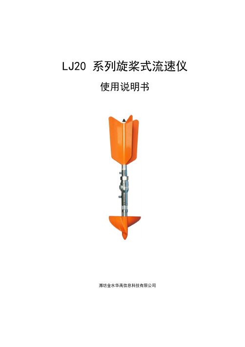
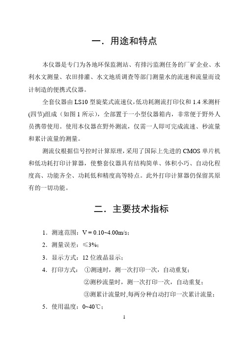
LJ20 系列旋桨式流速仪使用说明书潍坊金水华禹信息科技有限公司目次1概述 (1)1.1主要用途及适用范围 (1)1.2型号的组成及其代表意义 (1)2主要技术性能及参数 (1)3结构特征与工作原理 (2)4安装 (5)5使用、操作及维护 (6)5.1使用前的准备 (6)5.2流速与转子速率的关系 (6)5.3使用、操作及注意事项 (8)5.4维护、保养及注意事项 (8)6故障分析与排除 (11)7产品配置清单 (11)8保修及服务 (13)使用说明书1概述1.1 主要用途及适用范围LJ20 系列旋桨式流速仪是一种在水文测验中进行流速测量的常规通用型仪器,用于江河、湖泊、水库、水渠等过水断面中预定测点的时段平均流速的测量,亦可用于压力管道以及某些科学实验中进行流速测量。
LJ20 系列旋桨式流速仪执行GB/T11826-2002《转子式流速仪》等相关国家标准。
LJ20 系列旋桨式流速仪广泛适用于水文测验、水利调查、农田灌溉、径流实验等,亦可适用于水电、环保、矿山、交通、地质、科研院所、市政等行业或部门进行相关流速或流量的监测。
1.2 型号的组成及其代表意义2主要技术性能及参数1)旋桨回转直径:Φ125mmLJ20 系列旋桨式流速仪2)旋桨水力螺距b:200mm(理论值)3)起转速度v0:0.03m/s4)临界速度v k:约0.13m/s(以实际检定值为准。
据统计分析,v k远小于上述值。
)5)测速范围:0.05m/s~15m/s6)输出信号:磁激式开关接点通断信号7)信号数/转子转数:1/20(LJ20A 型)(每20 转1 个信号)1/1(LJ20C 型)(每 1 转1 个信号)8)开关接点容量:DC U≤24VI≤120mA9)接点工作次数:1×10710)全线相对均方差m:|m|≤1.5% (用于v≥v k时)11)相对误差δ:|δ|≤5%(用于v <v k时)12)工作水体环境:水温0℃~+40℃水深0.2m~50m悬移质含沙量≤50kg/m313)贮存环境:温度-25℃~+55℃湿度≤90%3结构特征与工作原理LJ20 系列旋桨式流速仪由旋桨、旋转支承部件、身架部件、干簧管部件、尾翼部件等组成(参见图1)。
手持式多普勒流速流量仪使用说明书
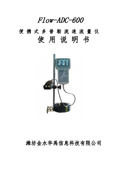
Flow-ADC-600便携式多普勒流速流量仪使用说明书潍坊金水华禹信息科技有限公司概述简便、快捷、准确、可靠、稳定的渠道与河流测量装置一直是各国流量测量专家的追求,受科学技术自身条件的限制,始终没能解决好这一难题。
但近几年美国将声学多普勒多点剖面流速测量技术应用在这一领域后,情况得到了根本性改变。
我公司引进Flow系列声学多普勒流速测量仪设计的流量测量系统已被广泛应用到水利、环保、城市供排水的流量、流速测量中。
应用声学多普勒效应简介多普勒效应是为纪念奥地利物理学家克里斯琴.约翰.多普勒而命名的,在声学领域中,当声源与接收体(即探头和反射体)之间有相对运动时,回声的频率将有所变化,此种频率的变化称之为频移,即多普勒效应。
现代社会中有大量应用这一物理原理而设计生产的仪表,如最常见的彩色多普勒超声二维结构图像仪、彩色多普勒血流图像仪,交通警测量汽车速度的微波测速仪以及水利学上的微波水表面流速仪等。
Flow-ADC-600 声学多普勒流速仪是应用当今最先进信号处理技术研发的多点、多层面流速分析仪,其最大特点是可任意按需要安装在被测河流或渠道侧面、底部或顶部,按现场情况任意设置向上、向下发射或向左、向右发射角度,从而准确测量出从水底到水面不同深层,从左到右不同距离上,根据多个流速数据、计算出平均流速。
根据现场水位的测绘能简单的测算各种规则或者非规则流体的截面面积绘制简单库容图。
大大简化了水利传统测流方法,并在准确性、稳定性,实时性上有了质的飞跃。
任意一个河流或渠道,只要有一台Flow-ADC-600测量仪,就能准确测出水的流态分布、流速数据及流量。
一、特点(1)、单只流速传感器,安装方便适合市政污下水管渠道、不满管管道、各种渠道、不规则河道、天然溪、排污口等流量测量并可隐蔽安装,可以做到长期稳定可靠工作。
(2)、既可顺流速、也可水位、水深方便统计。
(3)、大屏幕触摸屏,不仅有中文,还有配合图形,方便操作及流态分析。
超声波流量计说明书

§2.11 检查安装 ................. 52 §2.11.1 信号强度 ............ 52 §2.11.2 数据数量 ............ 53 §2.11.3 总传输时间、时差 .... 54 §2.11.4 传输时间比 .......... 54 §2.11.4 安装时注意的问题 .... 54
10
MKflo-2000F 系列中文版超声波流量计说明书
* 完备的输出信号包括集电极开路、频率信号 输出、4~20mA 电流环模拟输出等。带倍乘因 子(量程)的机内七位数长的正向、负向、 净流量及热量累积器独立工作,并可通过集 电极开路电路输出累计脉冲。
* 两路模拟输入可输入压力、温度液位信号。 配接温度变送器可实现热量测量。 * 用户选择标准校正曲线或用户实验校正曲线
何电路调整,使安装更容易简单。 * 可使用公制或英制单位,流量的单位可选用
几乎所有常用的中外通用单位,在带背光液 晶显示器上选择显示流量、流速、累积量及 日期时间等。 * 日、月、年流量累积功能可记录前 64 个运行 天、前 64 个运行月、前 5 个运行年的累积流 量;上、断电管理功能可记录前 64 次上电和 断电时间。 * 便携式流量计带有自动充电的机内电源,可 连续工作 8 小时。并备有外接直流电源输入插 座。
42 便携式电磁流速流量仪作业指导书

1.适用范围适用于指导MGG/KL-DCBⅡ型便携式电磁流速/流量仪的操作及维护。
1.1原理MGG/KL-DCBⅡ型便携式电磁流速/流量仪是基于法拉第电磁感应定律制作的。
当导电流体在沿流速传感器的交变磁场与电极中轴线垂直面运动时,导电流体切割磁力线产生感应电势,该电势被信号电极(在与导电流体平行线和磁力线相互垂直的流速传感器两侧壁上安装了两个对称的电极)所采集,此感应电势与流速大小成正比。
转换器通过该感应电势计算出流过流速传感器侧面的导电流体流速,此流速信号经流量显示仪放大,转换成与流速信号成正比的数字量信号,由此实现流速的测量。
流量显示仪将流速信号加上已经置入的水位数据及渠道基本结构参数通过显示仪内设置的水利数学模型进行运算,从而得到过水断面的水流量。
公式如下:Q(瞬时流量)=S(断面面积)*V(断面平均流速)置入(水利模型)1.2适用范围适用于指导MGG/KL-DCBⅡ型便携式电磁流速/流量仪的操作及维护。
使用人员在使用仪器前必须认真阅读本作业指导书并严格遵照执行。
1.3测量范围a)流速测量0.05m/s~10m/s(分辨率5mm/s),流量≤10000m³/s;渠底宽≤20m;渠深≤20m;边坡系数0~10;b)测量精度:±1.0%FS;1.4工作条件:介质电导:>20µs/cm介质温度:0℃~60℃环境温度:-10℃~50℃显示位数:水位5位,流速5位,流量5位注意:设备离开采样设备间前,需完整填写设备出入库记录;使用完毕后,及时清洁仪器,并完整填写设备使用记录;设备管理员负责仪器的周期检定和维修,并做好相关记录。
2.参考资料2.1 MGG/KL-DCBⅡ型便携式电磁流速/流量仪使用说明书。
3. 组装与简介3.1连接、组装测试仪将仪器电磁流速传感器、流量显示仪、侧流杆(或悬挂钢丝)等部件连接。
3.2参数设置3.2.1按键说明a)退出键:切换功能:轻按此键可使光标在设置项之间切换;退出功能:在参数设置状态下长按6s退出设置状态返回工作界面b)▲:巡加键:向前翻页或者修改参数时加1键。
流速仪说明书
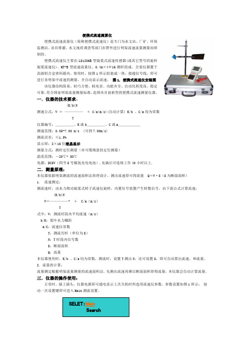
便携式流速测算仪便携式流速流量仪(简称便携式流速仪)是专门为水文站、厂矿、环保监测站、农田排灌、水文地质调查等部门在野外进行明渠流速流量测量而研制的。
便携式流速仪主要由LS1206B型旋桨式流速传感器(或其它型号的旋杯旋桨流速仪)、MT-B型流速流量仪、0.4m×4Ф16测杆组成。
全套仪器置于高级铝合金密码箱内。
使用时,按图1所示组装成一体,接通信号线,即可进行各明渠中流速的测量,并自动显示流速。
图1. 便携式流速仪安装图该仪器结构简易、轻巧方便、耗电省、功能齐全、自动化程度高、稳定可靠,符合国家明渠流量测量标准,是国内目前新型的便携式流速测量仪器。
一.仪器的技术要求:(K/b)N测速公式:V =—————+ C/a(m/s)(自动计算) K/b 、C/a均为常数T仪器编号:_____、K或b_____、C或a______测速范围:0.05-7.00 m/s (可到7.00m/s)测流误差:≤1.5%显示屏:2×16位液晶显示测量方式:测杆定位测量(亦可缆绳悬挂定位测量)温度范围:-20℃- 50℃电源:DC5V(四节5号镍氢充电电池),充满后可连续工作40小时以上.二.测量原理:本仪器依据明渠测流的流速面积法原理设计,测出流速即可得流量 Q=V·S(S为断面面积)1.流速测定:测流速时,由水力推动旋桨式转子流速仪旋转,内置信号装置产生转数信号,由下面公式计算流速:(K/b)NV=—————- + C/a(m/s)T式中:V:测流时段内平均流速(m/s)b/K:桨叶水力螺距a/C:流速仪常数T:测流历时(单位为S)N:T时段内信号数S:断面面积Q:流量本仪器使用时,K/b 、C/a均为常数,测流时,设置T测出N,还可设置S,即可自动算出流速,和流量。
2. 流量的计算:流量测定根据明渠流量测量的流速面积法,先测出流速再乘以断面面积即得流量,本仪器会自动计算流量。
三.仪器的操作使用:正常时,插上插头,仪器电源即可通电显示上次关机时所选用流速仪参数。
超声波流速仪 流速仪是如何工作的
超声波流速仪流速仪是如何工作的流速仪功能介绍1、迷你型手持主机便于用户携带和测量观测;2、大屏幕液晶显示具有连续背景光功能;3、内置完整时钟,便利用户校准和查询时间;4、配有数据读取软件,实现数据存储、打印和输出功能;5、实时显示瞬时流速和平均流速;6、测量模式分自动测量和手动测量,充分不同场合的用途。
性能特点1、测量精度高,量程宽,可测弱流,也可测强流;2、感应灵敏,辨别率高,不受启动流速限制;3、响应速度快,可测瞬时流速,也可测平均流速;4、量线性,不存在校正曲线的K、C值;5、无机械转动部件,不存在泥沙堵塞或水草、杂物缠绕等问题,较为适用于泥沙悬浮物含量高,水草等漂流物多的河流中测量。
地下水流向流速仪型号:MHY—05779随着国家进展,越来越多的工程需要建设和维护和修理。
但人们面对地下水渗流引起的潜在事故却一直没什么好方法。
如江河堤坝的管涌渗漏,矿山的涌水,道路铁路地基坍塌,地下铁路、隧道、涵洞、人防工程、地下建筑等的渗漏,目前通常只能消极面对,被动地应付,而这些问题的发生,都和地下水流动渗漏有关。
由于地下的土壤及基岩存在缝隙和空洞,在水的压力作用下,水会从高压区域流向低压区域,在流动的过程中,首先是那些细小的土壤颗粒随水流走,假如水压进一步变大并足以带动较粗颗粒时,渗流将进一步变成大,带走更多更粗的砂砾,结果事故就可能形成,当然实际过程要多而杂的多。
地下水流的流速、流向、渗透系数、水力坡度等都是紧要的地质参数,通过它们,我们就能对地质情形有一个总体的了解,对事态的进展趋势有一个总体的估量,但是地下几十米数百米,我们怎么能知道水的运动情形并测量出这些参数呢?传统的方法是打井,通过对取出的岩芯和抽水灌水,对地下水情况有一个粗略的估量,要想了解的略微细致一点,就要打多口探测井,费钱费时,结果还不很精准,随着事故的影响和损失越来越大,对潜在事故的推想和整治越来越迫切,对地下水测量提出了更高更新的要求,我们致力于这项讨论多年,研制出这款智能地下水参数测量仪,它能在单孔内就测出水的流速,流向等参数,结合其它测量手段和计算公式,能较精准地测出大部分紧要的地下水参数。
通达仪表 便携式多普勒流速仪 流量计 使用说明书
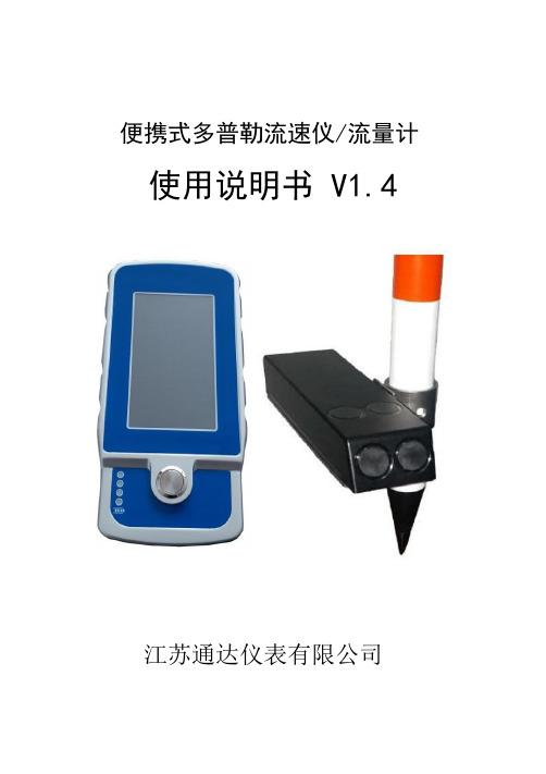
便携式多普勒流速仪/流量计使用说明书V1.4江苏通达仪表有限公司目录第1章产品概述 (1)1.1原理与特性 (1)1.1.1原理 (1)1.1.2特性 (1)1.2性能指标 (2)1.2.1手持机性能 (2)1.2.2传感器性能 (2)1.3应用领域 (3)第2章仪器组装连接 (4)2.1组装说明 (4)2.2电气连接 (5)2.3传感器寄存器表 (6)第3章手持机使用方法 (7)3.1页面说明 (7)3.2开机/关机 (9)3.3充电 (9)第1章产品概述图1-1流速仪声学多普勒流速仪是应用于河流、明渠及管道等工况的流速流量检测仪器。
其采用超声波探测技术,测量精度高、稳定性好、受环境因素影响小,无转动件、维护频次低、工作可靠性高,是便携流速流量测量的首选产品。
1.1原理与特性1.1.1原理多普勒效应,发射和接收的超声波频率差与流速建立关系,超声波发射与接收的时间差与液位建立关系,静压式液位用于需要测量液位量程较大的工况,环境温度测量用于修正超声波实际传播速度。
1.1.2特性✓传感器支持瞬时流量与累计流量功能✓能测静止水的流速✓能测非满管、满管及明渠的流量✓能测矩形、圆形、梯形、三角形截面的流量✓流速测量范围宽,0~10m/s,双向✓流速测量精度高,1mm/s误差✓超声测量液位精度高,误差1mm(2m以内)✓纯物理方法测量,免标定,免校准✓支持静压测液位✓支持温度补偿流速测量与液位测量✓ModbusRTU协议✓传感器防护等级IP68,支持长期水下工作✓便携式方案:传感器+手持机+测量杆,手提箱容纳所有配件✓手提箱尺寸:435*320*135mm1.2性能指标1.2.1手持机性能手持机尺寸187*91*30mm重量0.3kg存储温度-20℃~60℃相对湿度5%~85%(无冷凝)防护等级IP67充电方式直充待机时长持续工作8小时显示参数流速、液位、温度、流量现场显示带背光的 4.3寸触摸屏数字接口RS485接口,Modbus协议。
流速仪测流方法简述

4、部分流量的计算:
由各部分的部分平均流速与部分面积之积得到部分流量,即 qi=ViAi 式中,qi、vi、Ai分别为第i个部分的流量、平均流速和断面积。 5、断面流量及其他水力要素的计算:
完
二、断面测量与流速测量
(一)断面测量:
河道水道断面的测量,是在断面上布设一定数量的测深垂线,施测各条测深垂线的 起点距和水深并观测水位,各测深垂线处的河底高程为:
河底高程=水位-水深 测深垂线的位置,应根据断面情况布设于河床变化的转折处,并且主槽较密,滩地较稀。 测深垂线的起点距是指该测深垂线至基线上的起点桩之间的水平距离。 测定起点距的方法有多种: 断面索法,适宜中小河流,可在断面上架设过河索道,并直接读出起点距,称此法 为断面索法; 仪器测角交会法,大河上常用仪器测角交会法。常用仪器为经纬仪,平板仪、六分仪等。如 用经纬仪测量,在基线的另一端(起点距是一端)架设经纬仪,观测测深 垂线与基线之间的夹角。因基线长度已知,即可算出起点距;
1、垂线平均流速的计算:
2、部分平均流速的计算:
3、部分面积的计算:
因为断面上布设的测深垂线数目比测速垂线的数目多,故首先计算 测深垂线间的断面面积。计算方法是距岸边第一条测深垂线与岸边构 成三角形,按三角形面积公式计算(左右岸各一个);其余相邻两条测深 垂线间的断面面积按梯形面积公式计算。其次以测速垂线划分部分,将 各个部分内的测深垂线间的断面积相加得出各个部分的部分面积。若 两条测速垂线(同时也是测深垂线)间无另外的测深垂线,则该部分面积 就是这两条测深(同时是测速垂线)间的面积。
目前最先进的是用全球定位系统(GPS)定位的方法,它是利用全球定位接收天空 中的三颗人造定点卫星的特定信号来确定其在地球上处位置的坐标,优点是不受 任何天气气候的干扰,24小时均可连续施测,且快速、方便、准确。
通达仪表 TD-60手持式电波 雷达 流速仪使用说明书

-I -TD-60手持式电波(雷达)流速仪使用说明书江苏通达仪表有限公司谢致谢首先对您选择通达仪表产品表示衷心的感谢!TD-60电波流速仪是一款先进的流速测量仪器,其使用雷达技术实现简单、快捷的非接触式水面流速测量。
仪器小巧轻便,便于携带,非常适合有洪水或者急流等不易使用入水式测量仪器的现场检测。
TD-60电波流速仪集成了很多领先技术。
例如使用精密的平面窄带阵列雷达传感器、FFT数字信号处理、流速方向识别、垂直和水平角度的自动校正等;该仪器可以测量的最大流速是20m/s,检测灵敏度高。
流速仪带有彩色大屏幕液晶LCD,内嵌指引式菜单式软件,非常方便用户操作。
我们非常希望用户在使用TD-60电波流速仪之前阅读本手册,这样您将会更好的掌握如何使用这台先进的测速仪器。
本手册详细介绍了TD-60电波流速仪的使用方法、维护及注意事项等。
——江苏通达仪表有限公司全体员工-I-TD-60使用说明书✧注意事项及使用限制条款注意:江苏通达仪表有限公司的产品设计制造均安全可靠,请正确使用(按照所示文本说明),并完全遵守下列注意事项,则不会对仪器和人体造成危害。
注意本手册的使用者必须清楚此仪器及其附件可能产生的危险。
所有操作者在操作此仪器之前都应熟知本章节中的安全须知和警告。
如不遵守操作说明,则可能降低仪器的性能。
图例:说明:注意/警示涉及在运输、使用、维护过程中的注意事项,务必仔细阅读。
需注意的事项如下:✧操作环境及用电注意事项警告:不要在有或可能具有易燃易爆气体的场所中使用仪器。
注意:不要将仪器接触水面或者放入水中。
注意:不要将仪器放置于极端温度中,避免静电。
✧仪器操作注意:无论在使用、保存或运输仪器的过程中,都应小心取放,-I--II-切勿跌损。
✧电池警告:请使用章节2.4中规定的锂离子充电电池和充电器。
警告:电池电量低时请及时充电。
注意:废旧电池的丢弃需按照您的地区规定。
✧键盘按钮注意:不要过分用力按压仪器按键。
15版固定式超声波流量计说明书
一概述§1.1 引言欢迎您使用我公司研制生产的新一代UFT系列超声波流量计/超声波热量计/流量变送器。
新一代UFT系列超声波流量计/超声波热量计/流量变送器是在UFT第七版及第十一版超声波流量计的基础上,集11年专业生产制造超声波流量计的技术与经验,采用TI的MSP430FG4618低功耗单片机,最新开发的高性能、低价格、可靠性好、功能强大的全新系列产品。
新产品无论在测量精度、测量稳定性、通讯协议、使用方便性等方面都较原第7版超声波流量计有了很大的提高。
同时实现了生产过程中元器件参数无调整化,生产工艺更简单更可靠,产品一致性好,从而保证每一台出厂产品都达到最佳性能。
在软件操作菜单上继续延用第七版超声波流量计友好的用户界面,只是个别菜单的功能做了改动或增加,保证了公司的老用户非常简单容易的掌握。
新一代UFT系列超声波流量计/超声波热量计/变送器目前有四个不同式样的主板版本供用户选用,这四个版本分别称为第十二版、第十三版、第十四版和第十五版,简称为UFT12,UFT13,UFT14,UFT15。
本说明书适用于变送型(UFT12主板)、模块型(UFT13主板)、简易变送型(UFT14主板)、固定分体式(UFT13主板、UFT15主板)、固定一体式(UFT12主板、UFT13主板或UFT14主板)等型号的产品。
并对产品的安装、操作及通讯进行详细介绍。
§1.2 工作原理当超声波束在液体中传播时,液体的流动将使传播时间产生微小变化,其传播时间的变化正比于液体的流速,零流量时,两个传感器发射和接收声波所需的时间完全相同(唯一可实际测量零流量的技术),液体流动时,逆流方向的声波传输时间大于顺流方向的声波传输时间。
其关系符合下面表达式:Tup ²Tdown MD V T∆=sin2θ³F=900³π³D 2³V其中 其中q 为声束与液体流动方向的夹角 F 为瞬时流量(单位:立方米/小时) M 为声束在液体的直线传播次数 D 为管道的内径(单位:米) D 为管道内径 V 为流速(单位:米/秒) Tup 为声束在正方向上的传播时间 Tdown 为声束在逆方向上的传播时间DT=Tup-Tdown 时差§1.3 主板电气原理框图§1.4 特点新一代的UFT 系列超声波流量计/超声波热量计/流量变送器继承了原有产品的优点外,同时还具有以下特点:(1) 每个周期采样次数提高到了128次(第七版流量计每个周期采集50次) ,测量结果更稳定,能够满足绝大多数清水和污水以及多种化学液体的流量测量需求,甚至含有大量悬浮物的纸浆也可以测量。
LJD-10A打印式流速仪使用说明书
9
①仪器的拆洗: 在污水中测量,每经过一天的测量后都应在室内及时用汽油对仪器 按 LS10 型旋桨式流速仪说明书中的要求进行拆洗保养。 ②仪器不用时,应放在干燥的房间内。 ③拆卸、清洗及安装仪器以前,必须通晓仪器的结构和拆洗方法, 否则不能随便拆卸。 ④流速仪器长期存放后,在使用前必须清洗加油,检查仪器转动灵 活、信号正常后,方可使用。 ⑤若流速仪内轴承锈坏,或其它原因无法修理时应送回工厂修理并 重新率定。 ⑥较长时间不用时,应取出测流仪中的所有电池。
4
KAX ∑Q=TS( +C) T =SKAX+TSC 设:aT=SKA CT=TSC 则∑Q= aTX+ CT (m3) · · · · · · · · · · · · · · · · · · · · · · · · · · ·(8)
可见在此种条件下的累计流量主要为 aT 系数与信号数的乘积, 即X 个 aT 的累加值与 CT 6 的时间格式。 ⑤各种测量方法的系数计算及操作举例。 (a)测流速时的 av 值系数计算及具体操作。
7
由公式(3)可知: 流速 V = av =
t KAX
1 +C avi
(m/s)
若现有流速仪 K = 0.0995,C = 0.03,A = 20,X = 10,t = 0.1。 则有:av = t 0.1 = = 0.00503 KAX 20×0.0995×10
(m3/s)
Cq = SC = 0.5525×0.03 = 0.0166
将流速仪置于水深 0.39m (0.65m×0.6) 处,仪器的具体操作与测流
多普勒流量计使用说明书(单、便)

KAD 系列便携多普勒流量计~单声道在线多普勒流量计使 用 说 明 书(触摸屏)^MC量 制 00000251号目录…第一章概述----------------------------------2第二章性能参数------------------------------6第三章外形及安装尺寸------------------------6第四章传感器的安装--------------------------7第五章主机安装------------------------------10第六章按键与显示----------------------------11第七章功能/参数窗口详解---------------------12第八章一般故障及排除方法--------------------12、,;第一章概述1-1简要说明KAD系列在线超声多普勒流量计是一种根据多普勒方法进行测量的超声波流量计,它适用于测量含有大量杂质的液体和浆体。
既可以在管道外部测量液体的流量,也可以采用插入式传感器进行测量,用户可以根据现场条件选择传感器安装方式。
管外测量时无需对管道进行破损和改造。
安装和拆卸十分方便,为您省去了一笔可观的安装和拆卸费用,并且可使您的工艺不间断,这样也就将因仪表安装而造成停产的损失降到了最低。
但是管外安装时传感器必须定期维护。
而插入式测量稳定性可靠性更好,如果在条件允许情况下,采用插入式测量更为稳妥。
KAD在线超声多普勒流量计采用先进的单片机技术和超大规模集成电路,使其高度智能化,极大地提高了运行的稳定性,从而保证了仪表的精度和可靠性。
仪表的外壳采用进口全塑机箱,达到国际IP65的防护等级。
KAD在线超声多普勒流量计适用于城市污水处理厂、环保监测及矿山、油田、冶金、化工、炼油、造纸、食品等行业的城市排水、工业废水、生活污水、泥浆、纸浆、油水混合液等流量计量。
适用于钢铁、硬质塑料管等硬质管材,可以对多种管径和壁厚的管内含有悬浮固体颗粒或气泡的二相流体进行测量。
SpeedFlow速度测量仪器用户操作指南说明书

SpeedFlowMeasurement of velocityfor solidsSuperior with SolidsCONTENTS Page 1. System overview . . . . . . . . . . . . . . . . . . . . . . . . . . . . . . . . . . . . . . . . . . . . . . . . . . . . . . . . . . . . . . . . . . . . . . . 31.1 Using the optional C1-box . . . . . . . . . . . . . . . . . . . . . . . . . . . . . . . . . . . . . . . . . . . . . . . . . . . . . . . . . . . 32. Function . . . . . . . . . . . . . . . . . . . . . . . . . . . . . . . . . . . . . . . . . . . . . . . . . . . . . . . . . . . . . . . . . . . . . . . . . . . . . . 43. Safety . . . . . . . . . . . . . . . . . . . . . . . . . . . . . . . . . . . . . . . . . . . . . . . . . . . . . . . . . . .. . . . . . . . . . . . . . . . . . . . . 5Normal use . . . . . . . . . . . . . . . . . . . . . . . . . . . . . . . . . . . . . . . . . . . . . . . . . . . . . . . . . . . . . . . . . . . . . . . . 5 3.1Identification of hazards . . . . . . . . . . . . . . . . . . . . . . . . . . . . . . . . . . . . . . . . . . . . . . . . . . . . . . . . . . . . . 5 3.2Operational safety . . . . . . . . . . . . . . . . . . . . . . . . . . . . . . . . . . . . . . . . . . . . . . . . . . . . . . . . . . . . . . . . . . 5 3.3Technical statement . . . . . . . . . . . . . . . . . . . . . . . . . . . . . . . . . . . . . . . . . . . . . . . . . . . . . . . . . . . . . . . . 53.44. Mounting and installation . . . . . . . . . . . . . . . . . . . . . . . . . . . . . . . . . . . . . . . . . . . . . . . . . . . . . . . . . . . . . . . 6Supplied equipment . . . . . . . . . . . . . . . . . . . . . . . . . . . . . . . . . . . . . . . . . . . . . . . . . . . . . . . . . . . . . . . . 6 4.1Required tools . . . . . . . . . . . . . . . . . . . . . . . . . . . . . . . . . . . . . . . . . . . . . . . . . . . . . . . . . . . . . . . . . . . . . 6 4.2Mounting of the sensor . . . . . . . . . . . . . . . . . . . . . . . . . . . . . . . . . . . . . . . . . . . . . . . . . . . . . . . . . . . . . 6 4.3Mounting of the transmitter . . . . . . . . . . . . . . . . . . . . . . . . . . . . . . . . . . . . . . . . . . . . . . . . . . . . . . . . . 94.45. Electrical connection . . . . . . . . . . . . . . . . . . . . . . . . . . . . . . . . . . . . . . . . . . . . . . . . . . . . . . . . . . . . . . . . . . 106. Commissioning . . . . . . . . . . . . . . . . . . . . . . . . . . . . . . . . . . . . . . . . . . . . . . . . . . . . . . . . . . . . . . . . . . . . . . . 117. Menu structure of the SpeedFlow configuration program . . . . . . . . . . . . . . . . . . . . . . . . . . . . . . . . . . 128. System settings in detail . . . . . . . . . . . . . . . . . . . . . . . . . . . . . . . . . . . . . . . . . . . . . . . . . . . . . . . . . . . . . . . 139. Brief description of the PC operating software . . . . . . . . . . . . . . . . . . . . . . . . . . . . . . . . . . . . . . . . . . . . 15DRC tab . . . . . . . . . . . . . . . . . . . . . . . . . . . . . . . . . . . . . . . . . . . . . . . . . . . . . . . . . . . . . . . . . . . . . . . . . 15 9.1System tab . . . . . . . . . . . . . . . . . . . . . . . . . . . . . . . . . . . . . . . . . . . . . . . . . . . . . . . . . . . . . . . . . . . . . . . 16 9.29.3List tab . . . . . . . . . . . . . . . . . . . . . . . . . . . . . . . . . . . . . . . . . . . . . . . . . . . . . . . . . . . . . . . . . . . . . . . . . . 17Trend tab . . . . . . . . . . . . . . . . . . . . . . . . . . . . . . . . . . . . . . . . . . . . . . . . . . . . . . . . . . . . . . . . . . . . . . . . . 18 9.4Sensor tab . . . . . . . . . . . . . . . . . . . . . . . . . . . . . . . . . . . . . . . . . . . . . . . . . . . . . . . . . . . . . . . . . . . . . . . .189.510. Maintenance . . . . . . . . . . . . . . . . . . . . . . . . . . . . . . . . . . . . . . . . . . . . . . . . . . . . . . . . . . . . . . . . . . . . . . . . . 1911. Warranty . . . . . . . . . . . . . . . . . . . . . . . . . . . . . . . . . . . . . . . . . . . . . . . . . . . . . . . . . . . . . . . . . . . . . . . . . . . . . 1912. Troubleshooting . . . . . . . . . . . . . . . . . . . . . . . . . . . . . . . . . . . . . . . . . . . . . . . . . . . . . . . . . . . . . . . . . . . . . . 1913. Technical data . . . . . . . . . . . . . . . . . . . . . . . . . . . . . . . . . . . . . . . . . . . . . . . . . . . . . . . . . . . . . . . . . . . . . . . . 201. System overviewA complete measurement point consists of the following components:•Transmitter in DIN rail housing•Sensor accommodation for welding to the pipeline•Sensor (union nut, distance washer, sealing ring for adjusting to the wall thickness)•Operating instructions•C1-box (optional)The measuring sensor is connected to the transmitter using a shielded 4-wired cable with the length of the cable not exceeding 300 m.1.1 Using the optional C1-boxThe C1-box is a terminal block with a fuse and terminal resistor for connecting longer bus and supply lines.2. Function•The SpeedFlow is a measuring system which has been specially developed for measuring the speed of solids being transported.•The sensor uses the triboelectric effect. It is only used in metallic pipelines.•The electrodes fitted in the pipeline receive an electrical pulse from the solid particles as they pass.The received signals are evaluated using an auto-correlation process which thus calculates the speed.• A measurement point generally consists of the sensor, C1-box and the transmitter.Fig. 2: SpeedFlow sensor in the pipeline3. SafetyThe SpeedFlow measuring system has a state of the art, reliable design and and has been tested and found to be in a perfectly safe condition when it left the factory. Nevertheless the system components may present dangers to personnel and items if they are not operated correctly.The operating instructions can therefore be read in full and the safety instructions followed to the letter.If the device is not used correctly for its intended purpose the manufacturer's liability and warranty will be void.3.1 Normal use•The measuring system may only be installed in metallic pipes to measure the medium passing through them.It is not suitable for any other use or measuring system modifications.•Only genuine spare parts and accessories from SWR engineering may be used.3.2 Identification of hazards•Possible dangers when using the measuring system are highlighted in the operating instructions using the following symbols:•This symbol is used in the operating instructions to denote actions which, if they are not performed correctly may result in death or injury.Attention!• This symbol is used in the operating instructions to denote actions which may result in danger to property.3.3 Operational safety•The measuring system may only be installed by trained, authorised personnel.•In case of maintenance-work on the pipe or on components of the SpeedFlow sensor, make sure that the piping is in unpressurised condition.•Switch off the power supply before completing any maintenance work, cleaning work or inspections on the pipelines or the SpeedFlow components.•The sensor must be taken out of the pipeline before any welding work.•The components and electrical connections must be inspected for damage at regular intervals. If any signs of damage are found, they must be rectified before the devices are used again.3.4 T echnical statement•The manufacturer reserves the right to adjust technical data to technical development without notice.SWR engineering will be delighted to provide information about what the operating instructions is up to date and any amendments which have been made to it.4. Mounting and installation4.1 Supplied equipment•Transmitter in DIN rail housing•Sensor accommodation for welding to the pipeline•Sensor (union nut, distance washer, sealing ring for adjusting to the wall thickness)•Operating instructions•C1-box4.2 Required tools•Ø 20 mm-twist drill bit•32 mm open-ended spanner for union nut•Pliers for circlips (Ø 20 mm) to adjust the sensor to the wall thickness4.3 Mounting of the sensorProceed as follows to install the sensor:•Decide on the installation position on the pipe. It should be installed from the top on horizontal or angled pipelines.•Weld the sensor accommodation on to the pipe.•Drill through the pipe through the sensor (Ø 20 mm). Ensure that the borehole is not angled so that the sensor can be installed precisely later.Warning!•After drilling it is essential to check whether the drill bit has caused any burr on the borehole edges.Any burr on the pipe must be removed using a suitable tool. If the burr is not removed it may affect the sensor's calibration.•If the sensor is not installed immediately insert a dummy plug until it is installed (see also fig. 4). The dummy plug must be inserted together with the seal, two sealing rings and the circlips for shafts and secured using the union nut. Use a 32 mm open-ended spanner to tighten the union nut.Fig. 4: Installation of the sensoraccommodation and the dummy plug Distance washer 1 mmO-ring-type sealingring 19 x 2Sensor accomodationUnion nutCirclips for shaftsDummy plugqqqqqqq•Remove the dummy plug to insert the sensor.•The sensor is supplied ready-assembled for the specified wall thickness or, if no wall thickness was specified, to a wall thickness of 4 mm. Check again that it is correctly adjusted before installation (see table). If necessary the wall thickness must be remeasured with a depth gauge. The weld-on socket is93 mm long. It is important that the sensor does not project into the pipe. The sensor may be up to1 mm inside the pipe wall without this causing a measurement error.Wall thickness (mm)Position on the sensor neck Number of distance washers3.04.05.56.58.09.010.511.513.014.011223344552121212121•Now the sensor is put into the sensor accommodation and screwed with the union nut according to figure 5a.Fig. 5a: Installation of sensor accommodation and sensorSensor accommodationO-ring-type sealing ring 19 x 2Distance washer 1 mm Circlip for shafts 20 x 1.2Distance washer 1 mm Union nut Sensorqqqqq qq12 • and align it longitudinally to the pipe axis as marked on the sticker (Fig. 5b). The two sensor-rods must beinline with the flow. Then seal the measurement point with the union nut.Fig. 5b: Sensor alignment▼Flow d irectio n4.4 Mounting of the transmitter•The entire transmitter can be installed at a maximum distance of 1 km from the sensor.The housing is prepared for installation on a DIN rail to DIN EN 60715 TH35.Fig. 6: DIN rail housing for the transmitterFig. 7: Field housing for the C1-box5. Electrical connectionFig. 9: Electrical connection of the transmitter6. CommissioningCheck the following:•The correct connection between the sensor and transmitter.•The correct installation of the sensor on the internal wall of the transport pipe.If despite the above being correct the measurement is still not successful, consult SWR.Commissioning the SpeedFlowThe sensor is an absolute measuring device and must be parameterised during the commissioningprocedure. The menu functions in the supplied SpeedFlow configuration program are essentially self-explanatory. The program has been tested with all current Windows operating systems.The connection may be made using the RS 232 C interface (socket in the front panel) using the supplied cable or using the integral RS 485 interface (bus-capable) on screw terminals 11 and 12. By assigningdifferent addresses to the various transmitter the devices can be actuated in the bus using the ModBusprotocol. The following is a brief introduction as a summary.All the changed values must be saved by exiting the menu level and confirming the save function.Starting the menu After starting the SpeedFlow configuration program, open the interface (COM1to 10 can be selected). Fix the baud rate at 9600 Bd.Set the address of the transmitter (standard = 1).Current output The output values are set in menu points 3.1 to 3.8.The output value (current) is assigned to the measuring range here.Standard 0 = 4 mAMax = 20 mAThe measuring range filter is used to adjust to slower recording devices or acontinuous output at the analogue output.Alarms can be entered by the user in menu 2.Analogue output is modified in menu 3 and can be adjusted here to suit theuser's requirements. (Between 0 - 22 mA)Storage After making changes they can be saved using menu point Device Program.If you confirm Overwrite calibration the change will be made.Following the menu parameters in detail:7. Menu structure of the SpeedFlow configuration program1. Measuring range1.1 T ag no Adjust material (10 digits)1.2 Start of measuring range Range 0 (999)1.3 End of measuring range Range 0 (999)1.4 Filter value Range 0.1 ... 99.9 s2. Alarms2.1 Alarm 12.1 Alarm type Select: Min / Max / None2.2 Alarm value-10 to 110 % in physical units2.3 Alarm down time Range 0.1 ... 99.9 s2.4 Alarm hysteresis0.1 ... 99.9 %2.5 Operating mode Select: Working / Closed-circuit principle2.6 Sensor alarm Alarm for sensor error: On / Off3. Analogue output3.1 Start of range Range: 0 ... 22 mA (standard: 4 mA)3.2 End of range Range: 0 ... 22 mA (standard: 20 mA)3.3 MIN limit Range: 0 ... 22 mA (standard: 3 mA)3.4 MAX limit Range: 0 ... 22 mA (standard: 20 mA)3.5 Alarm value Range: 0 ... 22 mA (standard: 3 mA)3.6 Filter time Range: 0.1 ... 99.9 s (standard: 1 s)3.7 Calibration: 4 mA Adjust output current (4 mA calibrated)3.8 Calibration: 20 mA Adjust output current (20 mA calibrated)8. System settings in detail1. MEASURING RANGE1.1 T ag no.Freely selectable designation of the measuring medium or place,max. 10 characters1.2 Start of measuring rangeEnter the value of the required start of the measuring range.Normally 0.0.1.3 End of measuring rangeEnter the value of the required end of the measuring range.1.4 Filter valueAdjustable damping for the display in seconds.Range: 0.1 ... 99.9 s2. ALARMSEffect on the relay2.1 Alarm typeMin/Max - upper or lower limit value2.2 Alarm valueTrigger thresholdRange -10 ... 110 % of the measuring range values in physical units.2.3 Alarm down timeResponse time for how long the value must be below or above the limit valuebefore the alarm relay switches. Range: 0.1 ... 99.9 s2.4 Alarm hysteresisValue to reset the alarm.Range: 0.1 ... 99.9 % of the defined measuring range.2.5 Operating modeSelect the contact: Work or closed-circuitNO (working current) - NC (closed-circuit current)2.6 Sensor alarmAlarm for sensor errorON /OFF3. ANALOGUE OUTPUT3.1 Start of rangeValue to be set for minimum current output.(Standard 4 mA) - Range 0 ... 22 mA3.2 End of rangeValue to be set for maximum current output.(Standard 20 mA) - Range 0 ... 22 mA3.3 MIN limitMinimum current output value to be set. Range 0 ... 22 mA (standard 3 mA)3.4 MAX limitMaximum current output value to be set.Range 0 ... 22 mA (standard 20 mA)3.5 Alarm valueOutput value to be set for alarm (sensor error or internal alarm), at the same time the relay drops out.Range 0 ... 22 mA (standard 3 mA)3.6 Filter timeDamping to be set for the current output.Range 0.1 ... 99.9 s (standard 1 s)3.7 Calibration 4 mAMin. output current to be setAdjust to the external measuring system (if display is different).Adjust the output current to 4 mA using the and keys.3.8 Calibration 20 mAMax. output current to be setAdjust to the external measuring system (if display is different).Adjust the output current to 20 mA using the and keys.<><>9. Brief description of the PC operating softwareThe “SPF Service V.5.xx (E)” PC software can communicate with a sensor via RS 232 (front connector on the rail [DRC]) or via RS 485 (screw-terminal).The ModBus RTU log is used.•Interface standard is 9600 baud, 8 data bits, even parity, 1 stop bit.•Standard sensor address is 1.•Only one point-to-point connection can be established with one sensor via RS 232.• A bus system can be established via RS 485.• 1 sensor can be portrayed with the standard PC software.•Up to 10 sensors can be portrayed with an optional PC software.All settings required to operate the system can be activated via the PC software.•Interfaces and log file settings (data logger function) are activated in the System tab.•Current output, the signal’s measuring range, alarms and relay actions are set in the DRC tab.•Parameters for improving the measurement procedure are set in the Sensor menu.•The List and Trend tabs provide an overview of the measurement results from the measuring points.9.1 DRC tabSettings for customer system signals, see section 7.9.2 System tabLanguage:•German or English can be selected.Backup files:•Saving program data:Saves the settings from the PC program in a file so that they are available during the next start-up.These are automatically saved at the end of the program.•Save sensor parameters in a file / load sensor parameters from a file:Here, the measuring point parameters (DRC and sensor) can be saved into and read back from a file.•All backup files are saved in text format and can be opened with a normal text program. Communication:•COM port (COM1 to 10) of the interface used on the PC.• The baud rate for the communication must be the same on both devices.• If the baud rate for the DRC is changed, the new transmission rate will only apply after the DRC has been switched off and on again.• ModBus query rate and Timeout:Here, the intervals at which a query is sent to the connected system is set along with the time frame in which the response can be expected.Logging (PC data logger):• A log file is created for the sensor. The logs are saved as CSV files.•The decimal separator (comma or point) can be defined by CSV with decimal point.•The logging time interval can be entered as Log interval [ms].•The file name is automatically filled in with the ModBus address and serial number of the sensor in order to enable clear identification.•Automatic numbering of the files can be activated with the Auto-Increment option.The file numbers then increase each day (at midnight) and each time the program is started.•The file number can be manually adjusted with “Increase no.” or “Reset no.”.•The file path and active logging can be set in the footer.No COM-port scan (auto-start):If this option is selected, when starting, the software immediately begins with the most recently configured port and protocol settings.9.3 List tabHere, the sensor is portrayed in an overview list.Up to 10 sensors can be managed with the optional PC software.The sensor is portrayed with its main measurement value Vm and several secondary measurement values which provide information about the quality and condition of the measuring point.All values in this list are held in the log file and portrayed as trend lines (Trend tab).9.4 Trend tabAll values measured by the sensor from the overview list (List tab) are portrayed here as trends.Vm and Vcc are scaled on the left scale and all other values are scaled on the right scale.If upper and lower scale values are entered in the grey fields , these will be used - if the fields remain empty,automatic scaling will take place. With Zoom and Pos , the signal’s resolution and history can be set.9.5 Sensor tabThe measurement parameters, measurement values and quality numbers of the currently selected sensor are portrayed here. These parameters are provided as default settings or, if necessary, are selected when starting upthe sensor for the first time and permanently saved in the sensor.These parameters should only be set by trained personnel - as a rule by SWR employees - and should only be adjusted in special cases.10. Maintenance•Switch the power supply off before all maintenance and repair work on the measuring system.The transport pipe must not be operational to replace the sensor.•Repair and maintenance work may only be carried out by electricians.•The system requires no maintenance.11. WarrantyOn condition that the operating conditions are maintained and no intervention has been made on the device and the components of the system are not damaged or worn, the manufacturer provides a warranty of 1 year from the date of delivery.In the event of a defect during the warranty period, defective components will be replaced or repair at SWR's plant free of charge at discretion. Replaced parts will become SWR's property. If the parts are repaired or replaced at the customer's site at its request, the customer must pay the travelling expenses for SWR's service personnel.SWR cannot accept any liability for damage not suffered by the goods themselves and in particular SWR cannot accept liability for loss of profit or other financial damages suffered by the customer.Warning!The electrical installation may only be inspected by trained personnelProblem Cause MeasureMeasuring system does not work.POW LED not lit.RUN LED not lit.Power supply interrupted.Check the power supply.Cable break.Check the connection cables for a possible cable break.Fuse defective.Replace fuse.Device defective.Notify SWR and rectify the error as instructed on the telephone.Measuring system does not work.POW LED lit.RUN LED not lit.Microprocessor does notstart.Switch the power supply off and on again.Remove programming cable.Measuring system works.POW LED lit. RUN LED flashes quickly.No sensor communication.Sensor defective.Cable break between sensor and measuring system. Sensor connected incorrectly.Check connection cable.Sensor defective.Replace sensor.Sensor not receiving 24 Vsupply.Make sure the power supply is connected.Excessive voltage drop in thesupply cable to the sensor.Increase supply cable cross-section.Measuring systemoutputs incorrect values.Calibration incorrect.Calibration factor changed. Normal V = 1Switch output relaychatters.Hysteresis too low.Increase hysteresis. Check for fault caused by external consumer.Do not open, as otherwise the warranty claim expires!12. T echnical dataSensor Housing material Stainless steel 1.4571Protection category IP 65, dust Ex zone 20 or gas Ex zone 1 (optional)Operating temperature Sensor tip -20 ... +80 °C Optional: -20 ... +200 °C Sensor electronic: 0 ... +60 °C Max. working pressure 1 bar, optional 10 bar Sensor tip material Tungsten carbite Transmitting power Max. 5 mW Weight Approx. 1.5 kgDimensions Ø 60, Ø 20, L 320 mm (incl. rod length)Accuracy ± 1 % in calibrated rangeTransmitter Power supply 24 V DC ± 10 %Power consumption 20 W / 24 VA Protection category IP 40 to EN 60 529Operating temperature -10 ... +45 °C Dimensions 23 x 90 x 118 (W x H x D)WeightApprox. 172 g DIN rail mountingDIN 60715 TH35Connection terminals Cable cross-section 0,2 – 2,5 mm² [AWG 24-14]Current output signal 4 ... 20 mA (0 ... 20 mA), load < 500 WAlarm output Relay with switching contact - Max. 250 V AC, 1 A Data backupFlash memory (A l l r i g h t s r e s er v e d .)SWR engineering Messtechnik GmbHGutedelstraße 31 · 79418 Schliengen (Germany)Fon +49 7635 827248-0 · Fax +49 7635 827248-48 · Superior with Solids。
便携式明渠流速/流量计安装使用说明书

第2页
开流仪表有限公司
测量连接
6.1.2 充电端口:用于电磁流量显示仪内部电池充电时与充电器的连接。
(注:对电磁流量显示仪内部电池充电时,必需关闭电磁流量显示仪的工 作电源工作开关,禁止在电池充电状态下工作。)
充电连接
6.1.3 通讯端口:用于脉冲输出和 RS-232 或 RS-485 通讯端口的连接。 6.2 流速传感器的组装: 流速传感器总成由流速传感器、流速仪尾翼和插杆组成,组装方法见下图。
m3/s 或 m3/h 0~10000 0~10.000 0~1000
流量单位 流量量程 流量系数 频率上限
第5页
0(m3/s )
10000 1 1000Hz
开流仪表有限公司
5 零点自动调整 流速传感器系数 小信号切除 信号阻尼系数
6
密码设置
60S 10.000 0~20 0~99
0-999999
第6页
开流仪表有限公司
4. 频率上限:本仪表频率输出范围为 1~1000Hz,用户可在此范围内任意设置。 第 5 页:
1、 零点测量:该项参数为零点自动调整功能。本仪表在使用前如果有零点偏 差,可以通过此项参数进行零点自动调整。
2、 传感系数:该项参数为流速传感器标定系数,每一台流速传感器都有一个 唯一的传感器标定系数,该系数由实际标定得到,并在合格证上标注,仪 表使用时此系数必须按合格证上标注的系数设置。
开流仪表有限公司
MGG/KL-DCB 型便携式
明渠流速/流量计使用说明
一、概述 MGG/KL-DCB 型便携式明渠流速/流量计是一种专
为水文监测、江河流量监测、农业灌溉、市政给 排水、工业污水处理等行业流速/流量测量而设 计的一种便携式测量仪表。它采用了特殊的微功 耗设计方案,全数字信号处理技术,使得仪表测 量更加稳定可靠,测量范围宽,测量精度高,可 广泛用于水文、水利、农灌、给排水等领域需要 经常移动测量的场合。