外文翻译---FIR数字滤波器的设计
实验五FIR数字滤波器的设计
实验五FIR数字滤波器的设计FIR数字滤波器(Finite Impulse Response)是一种数字滤波器,它的输出仅由有限数量的输入样本决定。
设计FIR数字滤波器的步骤如下:1.确定滤波器的要求:首先需要明确滤波器的频率响应、截止频率、通带和阻带的幅频响应等要求。
2.选择滤波器类型:根据实际需求选择合适的滤波器类型,如低通滤波器、高通滤波器、带通滤波器或带阻滤波器等。
3.确定滤波器的阶数:根据滤波器类型和要求,确定滤波器的阶数。
通常情况下,滤波器的阶数越高,能够实现更陡峭的频率响应,但会引入更多的计算复杂度。
4.设计滤波器的理想频率响应:根据滤波器的要求和类型,设计滤波器的理想频率响应。
可以使用常用的频率响应设计方法,如窗函数法、最小最大法或线性相位法等。
这些方法可以实现平滑的频率响应或者良好的阻带衰减。
5.确定滤波器的系数:根据设计的理想频率响应,通过反变换或优化算法确定滤波器的系数。
常用的优化算法包括频域方法、时域方法、最小二乘法或最小相位法等。
6.实现滤波器:将所得的滤波器系数转化为滤波器的差分方程形式或直接计算滤波器的频域响应。
7.评估滤波器性能:使用合适的测试信号输入滤波器,并对滤波器的输出进行评估。
可以使用指标,如频率响应曲线、幅度响应误差、相位响应误差或阻带衰减等指标来评估滤波器性能。
8.优化滤波器性能:根据评估结果,进行必要的修改和优化设计,以满足滤波器的要求。
通过以上步骤,可以设计出满足需求的FIR数字滤波器。
需要注意的是,FIR数字滤波器设计的复杂度和性能需要权衡与平衡,以满足实际应用的要求。
FIR滤波原理及verilog设计
FIR滤波原理及verilog设计FIR滤波器是一种基于有限长冲激响应(Finite Impulse Response)的数字滤波器,它主要用于对数字信号进行滤波处理,例如降噪、去除杂音和频带限制等。
本文将介绍FIR滤波的原理,并给出一个基于Verilog的FIR滤波器设计。
一、FIR滤波原理:FIR滤波器是一种非递归滤波器,其输出是输入信号的线性组合。
它通过计算输入信号与一组滤波系数之间的加权和来实现滤波。
每一个滤波系数决定了输入信号在输出中所占的权重,当输入信号通过滤波器时,每一个采样点都与滤波系数进行乘法运算,并将结果相加得到输出。
Y(n)=h(0)*X(n)+h(1)*X(n-1)+h(2)*X(n-2)+…+h(N-1)*X(n-N+1)其中,Y(n)为输出信号的当前采样值,X(n)为输入信号的当前采样值,h(i)为滤波器的滤波系数,N为滤波器的阶数。
二、FIR滤波器的设计:1.滤波器的阶数N的选择:2.滤波系数h(i)的计算:滤波系数的计算是根据所需滤波器的频率响应来确定的。
常见的计算方法有窗函数法、频率采样法和最佳化法等。
具体的计算方法可以根据不同的需求进行选择。
三、基于Verilog的FIR滤波器设计:以下是一个基于Verilog的FIR滤波器设计示例,该设计以32阶FIR滤波器为例。
```verilogmodule FIR_filterinput wire clk,input wire reset,input wire signed [15:0] X,output reg signed [15:0] Yparameter N = 32;reg signed [15:0] delay_line [N-1:0];parameter signed [15:0] h [N-1:0] = {32'b0000_0000_0000_0000, /* 系数h0 */32'b0000_0000_0000_0000,/*系数h1*/...32'b0000_0000_0000_0000};/*系数h31*/if(reset) beginY<=0;for(int i=0; i<N; i=i+1) begindelay_line[i] <= 0;endendelse beginY <= (h[0] * X) + (h[1] * delay_line[0]) + ... + (h[N-1] * delay_line[N-2]);for(int i=N-1; i>0; i=i-1) begindelay_line[i] <= delay_line[i-1];enddelay_line[0] <= X;endendendmodule```在上面的Verilog代码中,FIR_filter模块包含了一个clk时钟信号、一个reset复位信号,以及输入信号X和输出信号Y。
fir滤波流程
fir滤波流程
FIR(FiniteImpulseResponse)滤波器是一种数字滤波器,它对输入信号进行滤波处理。
FIR滤波器的流程可以分为以下几个步骤:
1.定义滤波器的特性:首先,需要确定FIR滤波器的设计参数,包括滤波器的截止频率、通带和阻带的要求等。
这些参数将指导滤波器设计的具体过程。
2.选择滤波器的长度:FIR滤波器的长度由滤波器的阶数(taps的数量)决定。
阶数通常由滤波器设计的要求和计算能力等因素确定。
3.设计滤波器系数:利用设计参数和选择的滤波器长度,可以使用不同的设计方法来计算FIR滤波器的系数。
常见的设计方法包括窗口法、频率抽样法、最小最大法等。
4.输入信号:将要滤波的信号作为输入传递给FIR滤波器。
5.卷积运算:FIR滤波器的核心是卷积运算。
对输入信号和滤波器系数进行卷积运算,得到滤波后的输出信号。
卷积的过程可以通过滑动窗口的方式实现。
例如,对于一个3-tap的FIR滤波器,卷积运算的公式为:
y[n]=h[0]⋅x[n]+h[1]⋅x[n−1]+h[2]⋅x[n−2]
其中,y[n]是输出信号,x[n]是输入信号,ℎ[0],ℎ[1],ℎ[2]h[0],h[1],h[2]是滤波器系数。
6.输出信号:卷积运算得到的输出信号即为经过FIR滤波器处理后的信号。
FIR滤波器具有线性相位特性、稳定性和易于设计等优点,在
数字信号处理中得到广泛应用。
其滤波效果受到滤波器系数的选择和滤波器长度的影响,因此在设计FIR滤波器时需要仔细考虑滤波器的性能要求。
实验四FIR数字滤波器设计与软件实现
实验四FIR数字滤波器设计与软件实现
实验目的:
FIR(Finite Impulse Response)数字滤波器是一种常用的数字滤波器,本实验旨在通过设计和软件实现FIR数字滤波器,加深对数字滤波器的理解和应用。
实验材料和设备:
1.个人电脑
2. 数字信号处理软件(如MATLAB、Python等)
实验步骤:
1.确定滤波器的类型和设计要求,如低通滤波器、高通滤波器、带通滤波器等。
给定滤波器的截止频率、通带衰减和阻带衰减等参数。
2.使用指定的设计方法,如窗函数法、频率采样法等,进行FIR滤波器的设计。
根据设计要求选择合适的窗函数(如矩形窗、汉宁窗、布莱克曼窗等)或频率采样点。
3.进行FIR滤波器的软件实现。
在数字信号处理软件中,根据设计好的滤波器系数(也称为权值),通过卷积操作对输入信号进行滤波。
可以使用已有的滤波器设计函数或自行编写代码实现。
4.对输入信号进行滤波,观察滤波效果。
可以通过绘制输入信号和输出信号的时域图和频域图,分析滤波效果。
根据需要,可以对滤波器进行调整和优化。
5.根据实验结果,对滤波器的性能进行评估。
可以对比不同设计方法和参数选择的滤波器性能,分析其优缺点。
注意事项:
1.在选择滤波器的设计方法时,要根据实际需求和要求来选择。
不同方法有不同的适用范围和设计效果。
2.在进行滤波器实现时,要注意系数计算的精度和卷积操作的效率。
3.在进行滤波效果评估时,要综合考虑时域和频域等多个指标,避免单一指标的片面评价。
用窗函数法设计FIR滤波器
用窗函数法设计FIR滤波器窗函数法是一种常用的数字滤波器设计方法,特别是FIR(Finite Impulse Response)滤波器设计的一种方法。
FIR滤波器是一种非递归滤波器,可以实现信号的滤波,特定频率的增强或抑制,抗混叠等功能。
FIR滤波器设计过程可以分为两个步骤:确定滤波器的理论参数和设计窗函数。
第一步,确定滤波器的理论参数。
这些参数包括滤波器的采样频率,截止频率,通带和阻带的衰减要求等。
一般情况下,FIR滤波器的理论参数由滤波器的应用需求决定。
第二步,设计窗函数。
窗函数是用来限制FIR滤波器的单位冲激响应的长度的。
它决定了滤波器的频率响应特性和频率选择性。
窗函数可以通过Fourier级数展开来实现。
常用的窗函数有矩形窗、汉宁窗、汉明窗、布莱克曼窗等。
例如,以汉宁窗为例,下面是使用窗函数法设计FIR滤波器的具体步骤:1. 确定滤波器的理论参数。
如采样频率为fs,截止频率为fc,通带衰减要求为d1,阻带衰减要求为d22.将截止频率转化为数字频率。
由于数字信号是离散的,需要将模拟信号的截止频率转化为数字频率。
数字频率的单位为π。
3.根据截止频率和采样频率计算滤波器的长度N。
通常情况下,滤波器的长度N取一个奇数值,以确保能满足线性相位要求。
4.根据窗函数的性质确定窗函数的参数。
汉宁窗的参数为α=0.55.根据窗函数的长度N和参数α计算窗函数的系数。
例如,对于汉宁窗,窗函数的系数可通过下式计算得到:w(n) = 0.5 - 0.5 * cos(2πn/N) ,其中0≤ n ≤ N-16.根据窗函数的系数计算滤波器的单位冲激响应h(n)。
滤波器的单位冲激响应即为窗函数系数的离散时间傅里叶变换(DTFT),用于表示滤波器的频率响应特性。
7.根据滤波器的单位冲激响应h(n)可以计算出滤波器的频率响应H(f)。
频率响应可以通过滤波器的单位冲激响应h(n)的离散时间傅里叶变换(DTFT)计算得到。
8.根据设计要求来检验滤波器的频率响应特性是否满足要求。
经典滤波器设计范文

经典滤波器设计范文一、FIR滤波器设计FIR(Finite Impulse Response)滤波器是一种常用的数字滤波器,其特点是抗混叠性能好、线性相位响应、易于设计等。
FIR滤波器的设计通常分为两个步骤:滤波器的理想频率响应设计和具体的滤波器系数设计。
1.理想频率响应设计理想的低通FIR滤波器频率响应为单位脉冲响应的离散傅里叶变换,即H(e^jω) = sum(h(n)e^(-jωn)),其中h(n)为滤波器的单位脉冲响应。
通过将理想频率响应转换为时域单位脉冲响应,可以得到容纳在有限长度L的FIR滤波器中。
其中单位脉冲响应为:h(n) = (ω_0π)^-1 * sin(ω_0n)/(nπ),其中ω_0为截止频率。
2.系数设计对于FIR滤波器,系数设计是指对滤波器的单位脉冲响应进行窗函数的处理。
窗函数可以选择矩形窗、汉宁窗、海明窗等。
二、IIR滤波器设计IIR(Infinite Impulse Response)滤波器是另一种常用的数字滤波器,其特点是滤波器具有无限长度的单位脉冲响应。
与FIR滤波器不同,IIR滤波器的设计指标更多地侧重于滤波器的幅频响应与相位响应的设计。
1.巴特沃斯滤波器设计巴特沃斯滤波器是一种IIR滤波器的设计方法,其特点是在通带中具有均匀响应,即幅频特性较为平坦。
巴特沃斯滤波器设计的关键是选择滤波器阶数和截止频率。
2.预畸变滤波器设计预畸变滤波器是为了使滤波器的相频特性更加平坦而设计的,其主要应用在通信系统中。
预畸变滤波器一般采用线性相位结构,在设计时需要考虑相位补偿。
三、其他滤波器设计方法除了上述的FIR和IIR滤波器设计方法外,还有一些其他的滤波器设计方法,如小波滤波器设计、自适应滤波器设计等。
1.小波滤波器设计小波滤波器是在小波变换领域中常用的滤波器设计方法。
小波滤波器具有多尺度分析的特点,可以提供多分辨率的信号处理。
2.自适应滤波器设计自适应滤波器是根据输入信号的特性进行动态调整的一种滤波器设计方法。
fir数字滤波器设计流程
fir数字滤波器设计流程英文回答:Designing a FIR (Finite Impulse Response) digitalfilter involves several steps. I will explain the processin detail below.1. Specify the filter requirements: The first step isto clearly define the desired characteristics of the filter. This includes the filter type (low-pass, high-pass, band-pass, or band-stop), cutoff frequencies, passband ripple, stopband attenuation, and any other relevant specifications.For example, let's say I want to design a low-pass FIR filter with a cutoff frequency of 1 kHz, a passband rippleof 0.1 dB, and a stopband attenuation of 60 dB.2. Choose a filter design method: There are various methods available for FIR filter design, such as windowing, frequency sampling, and least squares. The choice of methoddepends on the desired filter characteristics and design constraints.Continuing with our example, I decide to use the windowing method for simplicity.3. Select a window function: In windowing, a window function is applied to the ideal impulse response of the filter to obtain a finite-length impulse response. Commonly used window functions include Hamming, Hanning, and Blackman.In our case, I choose the Hamming window function.4. Determine the filter length: The length of thefilter determines the trade-off between frequencyresolution and time-domain performance. Longer filters provide better frequency resolution but require more computational resources.To determine the filter length, I use a formula that takes into account the desired cutoff frequency and thewindow function.5. Generate the ideal impulse response: Using the desired filter characteristics and the determined filter length, I generate the ideal impulse response of the filter. This is done by applying the appropriate mathematical equations or algorithms.In our example, I generate the ideal impulse responseof the low-pass filter.6. Apply the window function: The next step is to apply the selected window function to the ideal impulse response. This is done by multiplying the window function with the ideal impulse response.For our low-pass filter, I multiply the Hamming window function with the ideal impulse response.7. Normalize the filter coefficients: The filter coefficients are normalized to ensure that the filter response meets the desired specifications. This istypically done by dividing the coefficients by the sum of their absolute values.In our case, I normalize the filter coefficients to ensure the passband ripple and stopband attenuation are within the specified limits.8. Implement the filter: Finally, the designed filter can be implemented in hardware or software for signal processing applications. This involves programming thefilter coefficients into a digital signal processor (DSP) or using a software library for FIR filtering.In conclusion, the process of designing a FIR digital filter involves specifying the filter requirements, choosing a design method, selecting a window function, determining the filter length, generating the ideal impulse response, applying the window function, normalizing the filter coefficients, and implementing the filter.中文回答:设计一个有限脉冲响应(FIR)数字滤波器涉及多个步骤。
实验6FIR滤波器设计

实验6FIR滤波器设计FIR(Finite Impulse Response)滤波器是一种数字滤波器,它的输出只取决于输入序列和固定的系数,没有反馈回路。
FIR滤波器在很多领域中都有广泛的应用,比如音频信号处理、图像处理等。
本实验中我们将设计一个FIR滤波器,主要包括滤波器的设计、滤波器的实现以及滤波器的性能评估。
首先,我们需要选择一个滤波器的类型和规格。
常用的滤波器类型包括低通滤波器、高通滤波器、带通滤波器和带阻滤波器等。
在本实验中,我们选择设计一个低通FIR滤波器。
接下来,我们需要确定滤波器的规格,包括截止频率、滤波器阶数和滤波器的类型等。
根据实际需求,我们选择截止频率为2kHz、滤波器阶数为64阶,滤波器类型为汉宁窗设计。
然后,我们需要确定滤波器的系数。
在本实验中,我们使用频率采样法设计滤波器。
首先,确定归一化截止频率:将实际截止频率除以采样频率,即2kHz/1MHz=0.002、然后,根据阶数和归一化截止频率计算出滤波器的系数。
在设计完成后,我们需要将滤波器转化为差分方程。
差分方程的形式为:y[n]=b0*x[n]+b1*x[n-1]+b2*x[n-2]+...+bN*x[n-N]其中y[n]是输出序列,x[n]是输入序列,b0,b1,b2,...,bN是滤波器的系数。
接下来,我们需要实现设计好的滤波器。
可以使用现有的FIR滤波器实现库,比如MATLAB中的“fir1”函数。
将输入序列输入滤波器,即可得到滤波后的输出序列。
最后,我们需要评估滤波器的性能。
常用的评估指标有幅频响应、相频响应和滤波器的群延迟等。
可以利用这些指标来评估滤波器的性能是否达到设计要求。
比如,可以绘制滤波器的幅频响应曲线来观察滤波器在不同频率下的增益情况。
综上所述,本实验主要介绍了FIR滤波器的设计、实现以及性能评估。
通过掌握FIR滤波器的设计方法和实现步骤,可以更好地应用FIR滤波器进行信号处理和滤波。
fir数字滤波器设计 开题报告

fir数字滤波器设计开题报告开题报告:FIR数字滤波器设计一、引言数字滤波器在信号处理领域扮演着重要的角色。
其中,FIR(Finite Impulse Response)数字滤波器是一种常见且广泛应用的数字滤波器。
本文将探讨FIR 数字滤波器的设计原理、算法和应用。
二、FIR数字滤波器的原理FIR数字滤波器是一类线性时不变系统,其输出仅与当前输入和过去输入的有限个采样值有关。
FIR数字滤波器的输出可以通过对输入信号的加权求和得到,其中每个加权系数称为滤波器的冲激响应。
FIR数字滤波器的冲激响应是有限长度的,因此称为有限冲激响应滤波器。
三、FIR数字滤波器的设计方法1. 窗函数法窗函数法是FIR数字滤波器设计中最常用的方法之一。
其基本思想是通过选择合适的窗函数来确定滤波器的冲激响应。
常见的窗函数有矩形窗、汉宁窗、汉明窗等。
通过对窗函数进行傅里叶变换,可以得到滤波器的频率响应。
2. 频率采样法频率采样法是一种直接设计FIR数字滤波器的方法。
该方法通过指定滤波器在频域上的理想响应,然后利用逆离散傅里叶变换将理想响应转换为冲激响应。
最后,对冲激响应进行截断,得到有限长度的冲激响应。
3. 最小二乘法最小二乘法是一种优化方法,用于设计FIR数字滤波器的冲激响应。
该方法通过最小化滤波器的输出与期望响应之间的均方误差来确定滤波器的系数。
最小二乘法可以通过求解线性方程组或应用优化算法来实现。
四、FIR数字滤波器的应用FIR数字滤波器在信号处理中有广泛的应用。
以下列举几个常见的应用领域:1. 语音处理FIR数字滤波器可以用于语音信号的降噪、去混响等处理。
通过选择合适的滤波器参数,可以去除语音信号中的噪声和回声,提高语音信号的质量。
2. 图像处理FIR数字滤波器在图像处理中也有重要的应用。
例如,可以利用FIR数字滤波器进行图像的平滑处理、边缘增强等。
通过调节滤波器的参数,可以实现不同的图像处理效果。
3. 生物医学信号处理FIR数字滤波器在生物医学信号处理中起着关键作用。
fir、iir 数字滤波器的设计与实现 概述及解释说明
fir、iir 数字滤波器的设计与实现概述及解释说明1. 引言在数字信号处理领域,滤波器是一种广泛应用的工具,用于去除或强调信号中的特定频率成分。
fir(Finite Impulse Response)和iir(Infinite Impulse Response)数字滤波器是两种常见的数字滤波器类型。
1.1 概述本文旨在介绍fir和iir数字滤波器的设计和实现方法,并比较它们的优缺点。
通过对这些内容的讨论,读者将能够了解到这两种滤波器的基本原理、设计方法以及实际应用中需要考虑的因素。
1.2 文章结构本文按照以下结构进行组织:第2节将详细介绍fir数字滤波器的设计与实现方法,包括其简介、设计方法和实现步骤。
第3节将类似地讨论iir数字滤波器,包括简介、设计方法和实现步骤。
第4节将对fir和iir数字滤波器进行对比,并讨论它们在性能、实现复杂度和工程应用方面的差异。
最后,在第5节中,我们将总结fir和iir数字滤波器的特点,并提供一些关于选择合适类型滤波器时需要考虑的要点。
1.3 目的本文的目的是帮助读者了解fir和iir数字滤波器的基本概念和工作原理,并对它们在实际应用中的设计和实现方法有一个全面的了解。
通过比较这两种滤波器的优缺点,读者将能够更好地选择适合自己需求的滤波器类型,并在实践中取得更好的效果。
以上是引言部分内容,主要说明了文章介绍fir、iir数字滤波器设计与实现的目标和结构。
2. fir数字滤波器的设计与实现2.1 fir数字滤波器简介fir(Finite Impulse Response)数字滤波器是一种常见的数字滤波器,其特点是只有有限个输入产生响应,并且在其单位冲激响应长度范围内,具有线性相位特性。
fir数字滤波器根据其系数序列进行信号的卷积运算,常用于信号处理、通信系统等领域。
2.2 fir数字滤波器设计方法fir数字滤波器设计可以采用多种方法,包括频域设计方法和时域设计方法。
实验七FIR数字滤波器设计及应用
实验七FIR数字滤波器设计及应用
FIR(Finite Impulse Response)数字滤波器是一种常用的数字信号处理技术,可用于实现信号滤波、频率选择、陷波、均衡等功能。
设计和应用FIR数字滤波器需要以下步骤:
1.确定滤波器的要求:确定滤波器的截止频率、带宽、陷波频率等参数,以及滤波器的类型(低通、高通、带通、带阻)。
2.选择滤波器的采样频率:根据信号的采样频率选择合适的滤波器采样频率,一般要满足采样频率的两倍以上。
3.设计滤波器的频率响应:根据滤波器的要求和采样频率,设计出理想的滤波器频率响应。
常用的设计方法有窗函数法、最小二乘法、频域优化法等。
4.确定滤波器的长度:根据滤波器的频率响应和性能要求,确定滤波器的长度。
一般来说,滤波器长度越长,频率响应越精确,但计算复杂度也越高。
5.编写滤波器的算法:根据设计的频率响应和滤波器长度,编写滤波器的算法代码,以实现滤波器的功能。
6.仿真和测试:通过仿真和实验测试,验证滤波器的设计和性能是否满足要求。
可以使用信号发生器生成测试信号,经过滤波器处理后,使用示波器观察滤波效果。
7.应用拓展:根据具体应用需求,可将设计好的FIR数字滤波器应用于实时信号处理、音频处理、图像处理等领域。
总之,设计和应用FIR数字滤波器需要经过滤波器要求确定、频率响
应设计、滤波器长度确定、算法编写、仿真测试等步骤,通过这些步骤可
以得到符合要求的FIR数字滤波器,并将其应用于各种实际信号处理场景。
外文翻译---FIR数字滤波器的设计
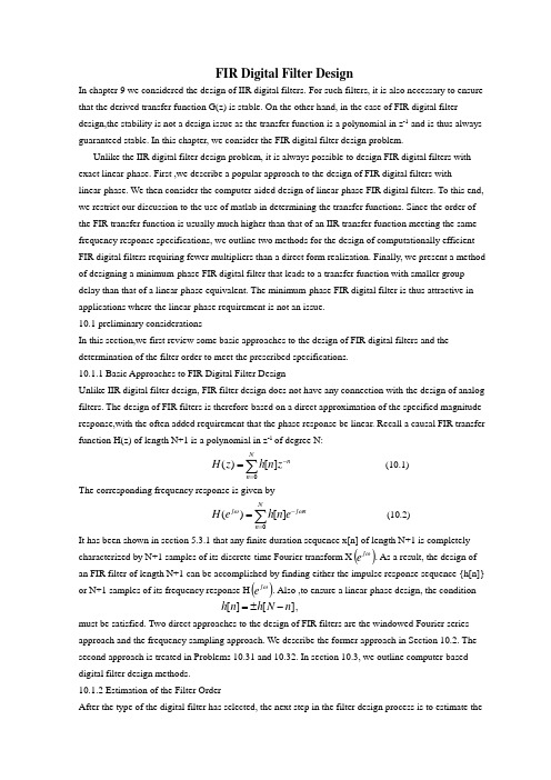
FIR Digital Filter DesignIn chapter 9 we considered the design of IIR digital filters. For such filters, it is also necessary to ensure that the derived transfer function G(z) is stable. On the other hand, in the case of FIR digital filter design,the stability is not a design issue as the transfer function is a polynomial in z -1 and is thus always guaranteed stable. In this chapter, we consider the FIR digital filter design problem.Unlike the IIR digital filter design problem, it is always possible to design FIR digital filters with exact linear-phase. First ,we describe a popular approach to the design of FIR digital filters with linear-phase. We then consider the computer-aided design of linear-phase FIR digital filters. To this end, we restrict our discussion to the use of matlab in determining the transfer functions. Since the order of the FIR transfer function is usually much higher than that of an IIR transfer function meeting the same frequency response specifications, we outline two methods for the design of computationally efficient FIR digital filters requiring fewer multipliers than a direct form realization. Finally, we present a method of designing a minimum-phase FIR digital filter that leads to a transfer function with smaller group delay than that of a linear-phase equivalent. The minimum-phase FIR digital filter is thus attractive in applications where the linear-phase requirement is not an issue. 10.1 preliminary considerationsIn this section,we first review some basic approaches to the design of FIR digital filters and the determination of the filter order to meet the prescribed specifications. 10.1.1 Basic Approaches to FIR Digital Filter DesignUnlike IIR digital filter design, FIR filter design does not have any connection with the design of analog filters. The design of FIR filters is therefore based on a direct approximation of the specified magnitude response,with the often added requirement that the phase response be linear. Recall a causal FIR transfer function H(z) of length N+1 is a polynomial in z -1 of degree N: ∑=-=Nn nzn h z H 0][)( (10.1)The corresponding frequency response is given by ∑=-=Nn nj j en h e H 0][)(ωω(10.2)It has been shown in section 5.3.1 that any finite duration sequence x[n] of length N+1 is completely characterized by N+1 samples of its discrete-time Fourier transform X ()ωj e . As a result, the design of an FIR filter of length N+1 can be accomplished by finding either the impulse response sequence {h[n]} or N+1 samples of its frequency response H ()ωj e . Also ,to ensure a linear-phase design, the condition ][][n N h n h -±=,must be satisfied. Two direct approaches to the design of FIR filters are the windowed Fourier series approach and the frequency sampling approach. We describe the former approach in Section 10.2. The second approach is treated in Problems 10.31 and 10.32. In section 10.3, we outline computer-based digital filter design methods. 10.1.2 Estimation of the Filter OrderAfter the type of the digital filter has selected, the next step in the filter design process is to estimate thefilter order should be the smallest integer greater than or equal to the estimated value. FIR Digital Filter Order EstimationFor the design of lowpass FIR digital filters, several authors have advanced formulas for estimating the minimum value of the filter order N directly from the digital filter specifications: normalized passband edge angular frequency p ω, normalizef stopband edge angular frequency s ω, peak passband ripplep δ,and peak stopband ripple s δ. We review three such formulas.Kaiser's Formula. A rather simple formula developed by Kaiser [Kai74] is given by πωωδδ2/)(6.1413)(log 2010p s s p N ---≅.We illustrate the application of the above formula in Example 10.1.Bellanger's Formula. Another simple formula advanced by Bellanger is given by [Bel81] 10.1 Preliminary Considerations 12/)(3)10(log 210---≅πωωδδp s s p N .Its application is considered in Example 10.2.Hermann's Formula. The formula due to Hermann et al.[Her73] gives a slightly more accurate value for the order and is given by πωωπωωδδδδ2/)(]2/))[(,(,2p p s p s s p s F D N ---≅∞)(,Where]6)(log 5)(log 4[log ]3)(log 2)(log 1[),(102101010210a a a a a a D p p s p p s p ++-++=∞δδδδδδδ,And]log [log 21),(1010s p s p b b F δδδδ-+=, Witha1=0.005309, a2=0.07114 ,a3=-0.4761, a4=0.00266, a5=0.5941, a6=0.4278, b1=11.01217, b2=0.51244.The formula given in Eq.(10.5) is valid for s δδ≥p . If s p δδ<, then the filter order formula to be used is obtained by interchanging p δ and s δ in Eq.(10.6a) and (10.6b).For small values of p δ and s δ, all of the above formulas provide reasonably close and accurate results. On the other hand, when the values of p δ and s δ are large, Eq.(10.5) yields a more accurate value for the order.A Comparison of FIR Filter Order FormulasNote that the filter order computed in Examples 10.1, 10.2 and 10.3, using Eqs.(10.3),(10.3),and (10.5), Respectively ,are all different. Each of these three formulas provide only an estimate of the required filter order. The frequency response of the FIR filter designed using this estimated order may or may not meet the given specifications. If the specifications are not met, it is recommended that the filter order be gradually increased until the specifications are met. Estimation of the FIR filter order using MATLAB is discussed in Section 10.5.1.An important property of each of the above three formulas is that the estimated filter order N of the FIR filter is inversely proportional to the transition band width (p s ωω-) and does not depend on the actual location of the transition band. This implies that a sharp cutoff FIR filter with a narrow transition band would be of very high order, whereas an FIR filter with a wide transition band will have a very low order.Another interesting property of Kaiser's and Bellanger's formulas is that the order depends on the product s p δδ. This implies that if the values of p δ and s δ are interchanged, the order remains the same.To compare the accuracy of the the above formulas, we estimate using each formula the order of three linear-phase lowpass FIR filters of known order, bandedges, and ripples. The specifications of the three filters are as follows:Filter No.1: 000112.0,0224.0,14375.0,10625.0====s p s p δδπωπω Filter No.2: 034.0,017.0,2875.0,2075.0====s p s p δδπωπω Filter No.3: 0137.0,0411.0,575.0,345.0====s p s p δδπωπω. The results are given in Table 10.1.Each one of the three formulas given above can also be used to estimate the order of highpass, bandpass, and bandstop FIR filters. In the case of the bandpass and bandstop filters, there are two transition bands. It has been found that here the filter order basically depends on the transition band with the smallest width. We illustrate the use of the Kasier's formula in estimating the order of a linear-phase bandpass FIR filter in Example 10.4.作者:Sanjit K.Mitra国籍:USA出处:Digital Signal Processing -A Computer-Based Approach 3eFIR数字滤波器的设计在第9章,我们考虑了IIR数字滤波器的设计。
fir数字滤波器的设计实验报告

fir数字滤波器的设计实验报告Title: Experimental Report on the Design of FIR Digital FilterIntroductionIn the field of digital signal processing, finite impulse response (FIR) filters play a crucial role in removing unwanted noise and extracting relevant information from digital signals. The design and implementation of FIR filters are essential for various applications, including audio processing, image processing, and communication systems. In this experimental report, we will discuss the design and implementation of an FIR digital filter and present the results of our experiments.Design of FIR Digital FilterThe design of an FIR digital filter involves determining the filter coefficients that will produce the desired frequency response. In this experiment, we used the window method to design a low-pass FIR filter with a cutoff frequency of 1 kHz. The filter order was chosen to be 64, which provides a good balance between the filter's frequency response and computational complexity.Implementation of FIR Digital FilterAfter designing the filter coefficients, we implemented the FIR digital filter using MATLAB. We generated a test signal consisting of a 2 kHz sine wave and added white Gaussian noise to simulate a noisy input signal. The input signal was then passed through the FIR filter, and the filtered output signal was obtained. Experimental ResultsWe analyzed the frequency response of the designed FIR filter and compared it with the ideal low-pass filter response. The frequency response of the FIR filter closely matched the desired response, demonstrating the effectiveness of the filter design. Furthermore, we observed that the filtered output signal effectively removed the high-frequency noise while preserving the low-frequency components of the input signal.ConclusionIn conclusion, the design and implementation of an FIR digital filter using the window method proved to be successful in this experiment. The experimental results demonstrated the ability of the FIR filter to remove unwanted noise and extract relevant information from digital signals. The knowledge gained from this experiment will be valuable in the practical application of FIR filters in various digital signal processing systems.In summary, the design and implementation of FIR digital filters are essential in digital signal processing. Through this experimental report, we have gained valuable insights into the design and implementation of FIR filters, as well as their practical application in removing noise and extracting relevant information from digital signals.。
实验七FIR数字滤波器设计及应用
实验七FIR数字滤波器设计及应用FIR数字滤波器设计及应用是一种常见的数字信号处理技术。
FIR (Finite Impulse Response)滤波器是一种线性时不变系统,其输出仅取决于输入和系统的过去有限数量的输入样本。
FIR滤波器的设计和应用可以实现信号的滤波、去噪、频率响应调整等功能。
以下是实验七FIR数字滤波器设计及应用的步骤:1.确定滤波器的设计要求,包括滤波器的类型(低通、高通、带通或带阻)、截止频率、通带衰减、阻带衰减等。
2. 使用数字滤波器设计软件,如MATLAB的fdatool工具箱或Python的scipy库,进行滤波器设计。
可以选择不同的设计方法,如频率采样法、窗函数法或最小最大化设计法等。
3.根据设计软件的结果,得到滤波器的系数序列。
这些系数将用于实现滤波器的数字滤波算法。
4.在应用程序中使用设计好的滤波器。
将输入信号送入滤波器,通过计算得到输出信号。
5.可以通过观察输出信号的频率响应、时域波形等进行性能评估。
根据需要,可以调整滤波器的设计参数,进行优化。
6.对于实时应用,需要将设计好的滤波器实现在硬件平台上,如FPGA或DSP芯片。
实验七FIR数字滤波器设计及应用的应用场景包括音频处理、图像处理、通信系统等。
在音频处理中,可以使用低通滤波器来去除音频信号中的高频噪声;在图像处理中,可以使用高通滤波器来增强图像的边缘信息;在通信系统中,可以使用带通滤波器来选择特定频段的信号。
总之,实验七FIR数字滤波器设计及应用是一种重要的数字信号处理技术,通过设计和应用滤波器可以对信号进行滤波、去噪和频率响应调整等操作,广泛应用于各个领域。
外文翻译---FIR滤波器设计技术
外文原文及翻译FIR滤波器设计技术摘要这份报告列举了一些设计FIR滤波器所使用的技术。
首先讨论了窗函数法和频率取样法的优点和缺点。
FIR数字滤波器也包含了许多优化设计的方法,这些优化技术减少了在频率采样时非采样频率点的误差频率。
对于用于设计数字滤波器的技术,例如matlab,进行了简明扼要的探讨。
介绍FIR滤波器的系统函数是一个1z 的多项式,因FIR滤波器的频率响应是频率的实函数,也称其为零相位滤波器。
N阶FIR滤波器的系统函数表示为(1)FIR滤波器是十分重要的,可应用于精确线性相位相应。
FIR滤波器的实现方式保证了它是一个稳定的滤波器。
FIR滤波器的设计可分为两部分:(i)近似问题(ii)实现问题解决近似问题,要通过四个步骤找出传递函数:(i)在频域内找出期望的或最理想的反应(ii)选择滤波器的阶数(FIR滤波器的长度N)(iii)选择近似结果中较好的(iv)选择一种算法寻找最优的滤波器传递函数选择部分结构处理实现传递函数的形式可能是线路图或程序。
本质上来说,有三种著名的FIR滤波器设计方法:(1)窗函数法(2)频率取样法(3)滤波器的优化设计窗函数法在该方法中,[Park87],[Rab75], [Proakis00]从理想的频率响应Hd(w)出发,一般来说,单位脉冲相应hd(n)的持续时间是无限的,所以在某种程度上说,它必须截断。
n=M-1约束着FIR滤波器的长度M。
以M-1截断的hd(n)乘以窗函数就得到了滤波器的单位脉冲响应。
矩形窗口的定义为w(n) = 1 0≦n≦M-1 (2)= 0 其它FIR滤波器的单位脉冲相应为h(n) = hd(n) w(n) (3)= hd(n) 0≦n≦M-1= 0 其它现在,多元化的窗函数w(n)与hd(n)相当于hd(w)与w(w)的卷积,其中,w (w)是窗函数的频域表示。
因此Hd(w)与w(w)的卷积为FIR数字滤波器的截断后的频率响应(4)频率响应也可以利用以下的关系式(5)由于非均匀收敛的傅里叶级数的不连续性,其自身的波纹前后有一种近似于不连续的频率响应,因此直接截断的hd(n)来获得h(n)将导致吉布斯现象。
fir滤波器计算公式
fir滤波器计算公式FIR滤波器(Finite Impulse Response Filter)是一种数字滤波器,它采用有限长度的冲激响应序列作为滤波器的系数。
FIR滤波器具有线性相位特性,可以实现任意频率响应。
其计算公式包括设计方法、频率响应、转移函数和系统函数等方面。
1.设计方法:FIR滤波器的设计方法主要有窗函数法、最小二乘法、频率采样法和优化算法等。
窗函数法是最常用的一种方法,它通过选择不同的窗函数对理想滤波器的频域响应进行窗函数逼近,从而得到FIR滤波器的系数。
2.频率响应:FIR滤波器的频率响应描述了滤波器在不同频率下的增益和相位变化情况。
一般情况下,FIR滤波器的频率响应是一个线性相位的低通、高通、带通或带阻滤波器。
频率响应可以通过滤波器的冲激响应序列进行计算,其中每个样点乘以相应的频率值,然后进行离散傅里叶变换(DFT)得到频率响应。
3.转移函数:FIR滤波器的转移函数可以通过滤波器的系数计算得到。
假设FIR滤波器的输入为x(n),输出为y(n),滤波器的系数为h(n),则滤波器的转移函数H(z)可以表示为:H(z)=h(0)+h(1)z^(-1)+h(2)z^(-2)+...+h(N)z^(-N)其中,N为滤波器的阶数。
4.系统函数:FIR滤波器的系统函数是指输入和输出之间的关系。
在时域中,FIR 滤波器的系统函数可以表示为:y(n)=h(0)x(n)+h(1)x(n-1)+h(2)x(n-2)+...+h(N)x(n-N)其中,h(n)为滤波器的系数。
FIR滤波器的计算公式主要涵盖了设计方法、频率响应、转移函数和系统函数等方面。
通过这些公式,可以对FIR滤波器的性能进行分析和设计,从而满足实际应用中的不同需求。
FIR滤波器的设计

FIR滤波器的设计FIR(Finite Impulse Response)滤波器是一种常见的数字滤波器,其特点是系统的冲击响应是有限时间内收敛到零的。
FIR滤波器的设计是一项重要的任务,通常涉及到选择滤波器的类型、截止频率和滤波器阶数等要素。
下面将介绍FIR滤波器的设计步骤及相关的技术。
FIR滤波器设计的第一步是选择滤波器的类型。
常见的FIR滤波器类型有低通、高通、带通和带阻滤波器等。
选择滤波器类型要根据具体的应用需求。
例如,对于音频信号处理,常使用低通滤波器来去除高频噪声。
对于图像处理,常使用带通滤波器来增强特定频段的图像信息。
在选择滤波器类型后,需要确定滤波器的截止频率。
截止频率是指滤波器在该频率以下或以上的信号成分被抑制的程度。
通常可以根据应用需求和信号特征来确定截止频率。
例如,对于音频信号处理,截止频率可以选择在人耳听觉范围之外的频率。
对于图像处理,截止频率可以选择在图像中较高或较低频段。
确定了滤波器类型和截止频率后,下一步是确定滤波器的阶数。
滤波器的阶数是指滤波器系统的长度,通常使用的是短时的冲激响应。
阶数的选择需要考虑到滤波器的性能需求和计算复杂度。
阶数较高的滤波器可以实现较窄的过渡带宽和更陡的滚降特性,但计算复杂度也会增加。
FIR滤波器的设计可以使用各种方法,常见的方法有窗函数法、频率取样法和最小二乘法等。
其中,窗函数法是最简单和最常用的方法之一、窗函数法的基本思想是先设计一个理想的滤波器,并通过乘以一个窗函数来控制滤波器的边界。
常用的窗函数有矩形窗、汉明窗、布莱克曼窗和凯泽窗等。
在窗函数法中,设计一个理想的滤波器通常通过频域方法来实现。
首先,在频域中定义一个理想的滤波器,即滤波器在截止频率之下或之上的振幅为1,其他频率处的振幅为0。
然后,通过将理想滤波器与选择的窗函数相乘来得到最终的滤波器。
乘积在时域的结果就是滤波器的冲激响应。
设计出滤波器的冲激响应后,就可以通过频率响应来评估滤波器的性能。
FIR数字滤波器设计实验_完整版
FIR数字滤波器设计实验_完整版FIR数字滤波器设计实验是一种以FIR(Finite Impulse Response)数字滤波器为主题的实验。
在这个实验中,我们将学习如何设计和实现一个FIR数字滤波器,以滤除特定频率范围内的噪声、增强信号或实现其他特定的信号处理功能。
以下是一个可能的FIR数字滤波器设计实验的完整版实验步骤和要求:实验目的:1.学习FIR数字滤波器的基本原理和设计方法。
2. 熟悉Matlab等数字信号处理软件的使用。
3.实践设计和实现一个FIR数字滤波器,以实现特定的信号处理功能。
实验步骤:1.确定实验所需的信号处理功能。
例如,设计一个低通滤波器以滤除高频噪声,或设计一个带通滤波器以增强特定频率范围内的信号。
2.确定数字滤波器的规格。
包括截止频率、滤波器阶数、滤波器类型(低通、高通、带通、带阻)等。
3. 使用Matlab等数字信号处理软件进行设计和仿真。
根据信号处理功能和滤波器规格,选择合适的设计方法(如窗函数法、频率采样法等),并设计出数字滤波器的系数。
4.对设计的数字滤波器进行性能评估。
通过模拟信号输入和滤波输出、频率响应曲线等方式,评估滤波器在实现信号处理功能方面的性能。
5.利用硬件平台(如DSP处理器、FPGA等)实现设计的FIR数字滤波器。
根据设计的滤波器系数,编程实现滤波器算法,并进行实时信号处理和输出。
同时,可以利用外部信号源输入不同类型的信号,进行滤波效果验证和性能测试。
6.对滤波器设计和实现进行综合分析。
根据实际效果和性能测试结果,分析滤波器设计中的优缺点,并提出改进方案。
实验要求:1.理解FIR数字滤波器的基本原理和设计方法。
2. 掌握Matlab等数字信号处理软件的使用。
3.能够根据信号处理要求和滤波器规格,选择合适的设计方法并设计出满足要求的滤波器。
4.能够通过模拟和实验验证滤波器的性能。
5.具备对滤波器设计和实现进行综合分析和改进的能力。
通过完成上述实验,学生可以深入理解FIR数字滤波器的原理和设计方法,掌握数字信号处理软件的使用,提升数字信号处理的实践能力,并了解数字滤波器在实际应用中的重要性和价值。
- 1、下载文档前请自行甄别文档内容的完整性,平台不提供额外的编辑、内容补充、找答案等附加服务。
- 2、"仅部分预览"的文档,不可在线预览部分如存在完整性等问题,可反馈申请退款(可完整预览的文档不适用该条件!)。
- 3、如文档侵犯您的权益,请联系客服反馈,我们会尽快为您处理(人工客服工作时间:9:00-18:30)。
FIR Digital Filter DesignIn chapter 9 we considered the design of IIR digital filters. For such filters, it is also necessary to ensure that the derived transfer function G(z) is stable. On the other hand, in the case of FIR digital filter design,the stability is not a design issue as the transfer function is a polynomial in z -1 and is thus always guaranteed stable. In this chapter, we consider the FIR digital filter design problem.Unlike the IIR digital filter design problem, it is always possible to design FIR digital filters with exact linear-phase. First ,we describe a popular approach to the design of FIR digital filters with linear-phase. We then consider the computer-aided design of linear-phase FIR digital filters. To this end, we restrict our discussion to the use of matlab in determining the transfer functions. Since the order of the FIR transfer function is usually much higher than that of an IIR transfer function meeting the same frequency response specifications, we outline two methods for the design of computationally efficient FIR digital filters requiring fewer multipliers than a direct form realization. Finally, we present a method of designing a minimum-phase FIR digital filter that leads to a transfer function with smaller group delay than that of a linear-phase equivalent. The minimum-phase FIR digital filter is thus attractive in applications where the linear-phase requirement is not an issue. 10.1 preliminary considerationsIn this section,we first review some basic approaches to the design of FIR digital filters and the determination of the filter order to meet the prescribed specifications. 10.1.1 Basic Approaches to FIR Digital Filter DesignUnlike IIR digital filter design, FIR filter design does not have any connection with the design of analog filters. The design of FIR filters is therefore based on a direct approximation of the specified magnitude response,with the often added requirement that the phase response be linear. Recall a causal FIR transfer function H(z) of length N+1 is a polynomial in z -1 of degree N: ∑=-=Nn nzn h z H 0][)( (10.1)The corresponding frequency response is given by ∑=-=Nn nj j en h e H 0][)(ωω(10.2)It has been shown in section 5.3.1 that any finite duration sequence x[n] of length N+1 is completely characterized by N+1 samples of its discrete-time Fourier transform X ()ωj e . As a result, the design of an FIR filter of length N+1 can be accomplished by finding either the impulse response sequence {h[n]} or N+1 samples of its frequency response H ()ωj e . Also ,to ensure a linear-phase design, the condition ][][n N h n h -±=,must be satisfied. Two direct approaches to the design of FIR filters are the windowed Fourier series approach and the frequency sampling approach. We describe the former approach in Section 10.2. The second approach is treated in Problems 10.31 and 10.32. In section 10.3, we outline computer-based digital filter design methods. 10.1.2 Estimation of the Filter OrderAfter the type of the digital filter has selected, the next step in the filter design process is to estimate thefilter order should be the smallest integer greater than or equal to the estimated value. FIR Digital Filter Order EstimationFor the design of lowpass FIR digital filters, several authors have advanced formulas for estimating the minimum value of the filter order N directly from the digital filter specifications: normalized passband edge angular frequency p ω, normalizef stopband edge angular frequency s ω, peak passband ripplep δ,and peak stopband ripple s δ. We review three such formulas.Kaiser's Formula. A rather simple formula developed by Kaiser [Kai74] is given by πωωδδ2/)(6.1413)(log 2010p s s p N ---≅.We illustrate the application of the above formula in Example 10.1.Bellanger's Formula. Another simple formula advanced by Bellanger is given by [Bel81] 10.1 Preliminary Considerations 12/)(3)10(log 210---≅πωωδδp s s p N .Its application is considered in Example 10.2.Hermann's Formula. The formula due to Hermann et al.[Her73] gives a slightly more accurate value for the order and is given by πωωπωωδδδδ2/)(]2/))[(,(,2p p s p s s p s F D N ---≅∞)(,Where]6)(log 5)(log 4[log ]3)(log 2)(log 1[),(102101010210a a a a a a D p p s p p s p ++-++=∞δδδδδδδ,And]log [log 21),(1010s p s p b b F δδδδ-+=, Witha1=0.005309, a2=0.07114 ,a3=-0.4761, a4=0.00266, a5=0.5941, a6=0.4278, b1=11.01217, b2=0.51244.The formula given in Eq.(10.5) is valid for s δδ≥p . If s p δδ<, then the filter order formula to be used is obtained by interchanging p δ and s δ in Eq.(10.6a) and (10.6b).For small values of p δ and s δ, all of the above formulas provide reasonably close and accurate results. On the other hand, when the values of p δ and s δ are large, Eq.(10.5) yields a more accurate value for the order.A Comparison of FIR Filter Order FormulasNote that the filter order computed in Examples 10.1, 10.2 and 10.3, using Eqs.(10.3),(10.3),and (10.5), Respectively ,are all different. Each of these three formulas provide only an estimate of the required filter order. The frequency response of the FIR filter designed using this estimated order may or may not meet the given specifications. If the specifications are not met, it is recommended that the filter order be gradually increased until the specifications are met. Estimation of the FIR filter order using MATLAB is discussed in Section 10.5.1.An important property of each of the above three formulas is that the estimated filter order N of the FIR filter is inversely proportional to the transition band width (p s ωω-) and does not depend on the actual location of the transition band. This implies that a sharp cutoff FIR filter with a narrow transition band would be of very high order, whereas an FIR filter with a wide transition band will have a very low order.Another interesting property of Kaiser's and Bellanger's formulas is that the order depends on the product s p δδ. This implies that if the values of p δ and s δ are interchanged, the order remains the same.To compare the accuracy of the the above formulas, we estimate using each formula the order of three linear-phase lowpass FIR filters of known order, bandedges, and ripples. The specifications of the three filters are as follows:Filter No.1: 000112.0,0224.0,14375.0,10625.0====s p s p δδπωπω Filter No.2: 034.0,017.0,2875.0,2075.0====s p s p δδπωπω Filter No.3: 0137.0,0411.0,575.0,345.0====s p s p δδπωπω. The results are given in Table 10.1.Each one of the three formulas given above can also be used to estimate the order of highpass, bandpass, and bandstop FIR filters. In the case of the bandpass and bandstop filters, there are two transition bands. It has been found that here the filter order basically depends on the transition band with the smallest width. We illustrate the use of the Kasier's formula in estimating the order of a linear-phase bandpass FIR filter in Example 10.4.作者:Sanjit K.Mitra国籍:USA出处:Digital Signal Processing -A Computer-Based Approach 3eFIR数字滤波器的设计在第9章,我们考虑了IIR数字滤波器的设计。