AEULO发热电缆用户使用手册
电缆使用说明书

电缆使用说明书电缆使用说明书电缆使用说明书本说明书仅适用于 35kv 及以下塑料绝缘电力电缆和控制电缆。
一、电缆型号、规格用户应根据国家现行颁布的电缆设计规范、规程,按照实际工程敷设环境条件,系统电压等级,负荷性质和负荷情况,并充分考虑工程发展裕度,来正确选择电缆的型号与规格。
二、产品交付验收产品到达目的地后,用户应即使进行验收,并办理签字等手续。
验收项目应包括:1、合格证(每盘、每件一份)2、质量保证书。
3、电缆的外包装物是否完好,有无破损。
4、电缆端头是否封帽,有无破损或密封不良等现象。
5、电缆盘是否明显变形、扭曲。
6、检查电缆外表是否完好,有无擦伤、擦破等现象。
7、电缆型号、规格、长度是否与货单一致。
三、电缆的装卸、运输、保管、现场放置等注意事项:1、装有电缆的电缆盘应竖直放置,严禁平方或叠放。
2、装卸电缆应逐盘叼装,严禁同时几盘吊装。
注意起重工具受力位置,不能在电缆盘边沿、侧面、加强筋位置直接受力,吊钩起吊应钩牢电缆盘中心孔;用叉车铲运时,要注意两叉臂与电缆盘两边同时受力,落地平稳。
3、装卸时使用的其重工具、钢丝绳、吊钩等,承载能力要大于电缆及包装物的总重量。
4、在车辆等运输工具上装运电缆时,电缆盘必须放稳,并用合适方法固定,防止互碰或翻倒。
5、严禁从高处推下装有电缆的电缆盘。
6、搁放电缆盘安放在平稳地方,保证电缆盘稳固,防止滚动碰撞损坏电缆和其他以外事故发生7、电缆短距离搬运,允许将电缆盘滚动,但滚动方向必须与箭头指示方向一致,否则易损坏电缆;另应采取措施,防止电缆盘滚动路径中地面上的凸起硬物挤伤电缆。
8、电缆储存,应避开有腐蚀性的气味、高温、易燃易爆等场所;电缆储存时应检查其端头密封,对分段后的电缆盘上的剩余电缆,应及时采取可靠的密封措施,防止电缆端头进水;电缆不宜长期露天存放。
四、电缆的敷设、安装电缆的敷设、安装应严格遵守GB50168-92 《电气装置安装工厂电缆线路施工及验收规范》,并应由取得资格证书的、有实际工作经验的人员担任。
电缆手册

armor, PVC sheath
力作用,但不能承受大的拉力。
交联聚乙烯绝缘钢带铠装聚乙烯护套电力电缆 To be laid underground(depth of burying: at least 0.7m above earth),
.Power cable with XLPE insulation steel tape the cable can bear certain mechanical force, but it can not bear great
Working Condition
1、Long-term working temperature by cable conductor is 90℃.
2、Max. temperature of cable conductor shall be no more than 250℃ during short circuit (the longest lasting time shall be no more than 5 seconds).
35kV及以下交联聚乙烯绝缘电力电缆 35 kV or Lower Power Cable with XLPE Insulation
本产品适用于固定敷设在交流50Hz,额定电压35kV及以 下的电力输配电线路上作输送电能用。与聚氯乙烯绝缘电力 电缆相比,交联电力电缆产品不仅具有优异的电气性能、机械 性能、耐热老化性能、耐环境应力和耐化学腐蚀性能的能力, 而且结构简单,重量轻,不受敷设落差限制,长期工作温度高 (90℃)等特点。
五、生产范围
1-导体 2-内屏蔽3-绝缘4-外屏蔽5-金属屏蔽6-填充7-绕包层8-内衬 层9-铠装层10-外护套 1.conductor 2.inner shielding 3.insulation 4.outer shielding 5.metallic shielding 6.filling 7.wrapped layer 8. inner layer 9.armored layer 10. outer sheath
Omega □FM 热电池两线温度传输器用户指南说明书

TX91Thermocouple T wo-Wire Temperature Transmitter e-mail:************** For latest product manuals:It is the policy of OMEGA Engineering, Inc. to comply with all worldwide safety and EMC/EMI regulations that apply. OMEGA is constantly pur-suing certification of its products to the European New Approach Directives. OMEGA will add the CE mark to every appropriate device upon certification. The information contained in this document is believed to be correct, but OMEGA accepts no liability for any errors it contains,and reserves the right to alter specifications without notice.WARNING: These products are not designed for use in, and should not be used for, human applications.Benelux:Managed by the United Kingdom Office Toll-Free: 0800 099 3344 TEL: +31 20 347 21 21FAX:+31206434643e-mail:*****************Czech Republic:Frystatska 184, 733 01 Karviná, Czech Republic Toll-Free: 0800-1-66342 TEL: +420-59-6311899FAX: +420-59-6311114 e-mail:*****************OMEGA’s policy is to make running changes, not model changes, whenever an improvement is possible. This affords our customers the latest in technology and engineering.OMEGA is a registered trademark of OMEGA ENGINEERING, INC.© Copyright 2010 OMEGA ENGINEERING, INC. All rights reserved. This document may not be copied, photocopied, reproduced,translated, or reduced to any electronic medium or machine-readable form, in whole or in part, without the prior written consent of OMEGA ENGINEERING, INC.RETURN REQUESTS / INQUIRIESDirect all warranty and repair requests/inquiries to the OMEGA Customer Service Department. BEFORE RETURNING ANY PRODUCT(S) TO OMEGA, PURCHASER MUST OBTAIN AN AUTHORIZED RETURN (AR) NUMBER FROM OMEGA’S CUSTOMER SERVICE DEPARTMENT (IN ORDER TO AVOID PROCESSING DELAYS). The assigned AR number should then be marked on the outside of the return package and on any correspondence. The purchaser is responsible for shipping charges, freight, insurance and proper packaging to prevent breakage in transit. Servicing Europe:FOR WARRANTY RETURNS, please have the following information available BEFORE contacting OMEGA:1.Purchase Order number under which the product wasPURCHASED,2.Model and serial number of the product under warranty, and 3.Repair instructions and/or specific problems relative to the product.FOR NON-WARRANTY REPAIRS, consult OMEGA for current repair charges. Have the followinginformation available BEFORE contacting OMEGA:1. Purchase Order number to cover the COST of the repair,2.Model and serial number of the product, and 3.Repair instructions and/or specific problems relative to the product.France:Managed by the United Kingdom Office Toll-Free: 0800 466 342 TEL: +33 (0) 161 37 29 00FAX:+33(0)130575427e-mail:**************Germany/Austria:Daimlerstrasse 26D-75392 Deckenpfronn, GermanyToll-Free: 0800 6397678 TEL: +49 (0) 7056 9398-0FAX:+49(0)70569398-29e-mail:*************United Kingdom: ISO 9001 Certified OMEGA Engineering Ltd.One Omega Drive, River Bend Technology Centre, Northbank, Irlam, ManchesterM44 5BD United Kingdom Toll-Free: 0800-488-488TEL: +44 (0) 161 777-6611FAX: +44 (0) 161 777-6622e-mail:**************.ukPage Section 1 Introduction 11.1 General Description . . . . . . . . . . . . . . . . . . . . . . . . . . . . . . . . . . .11.2 Features . . . . . . . . . . . . . . . . . . . . . . . . . . . . . . . . . . . . . . . . . . . . . .81.3 Models Available . . . . . . . . . . . . . . . . . . . . . . . . . . . . . . . . . . . . . .8 Section 2 Unpacking Instructions 9 Section 3 Installation 113.1 Mounting the TX91 . . . . . . . . . . . . . . . . . . . . . . . . . . . . . . . . . . . .103.2 Wiring the TX91 . . . . . . . . . . . . . . . . . . . . . . . . . . . . . . . . . . . . . . .16iPage Section 4 Calibration Instructions 184.1 Equipment Required . . . . . . . . . . . . . . . . . . . . . . . . . . . . . . . . . . .184.2 Set-up of Equipment . . . . . . . . . . . . . . . . . . . . . . . . . . . . . . . . . .194.3 Calibration Procedures . . . . . . . . . . . . . . . . . . . . . . . . . . . . . . . .20 Section 5 Troubleshooting Guide 25 Section 6 Accessories 26 Section 7 Specifications 27 Appendix AIntrinsically Safe Interconnection Diagram . . . . . . . . . . . . . . . . . . . . .30ii11.1 General DescriptionThe OMEGA ®TX90 Series Temperature Transmitters consist of the TX91 Miniature Two-Wire Thermocouple Transmitter and theTX92 Miniature Two-Wire RTD Transmitter. This manual is written for the OMEGA TX91 Thermocouple Transmitter.The TX91 Transmitter accepts thermocouple sensor types J, K, T,or E and will produce a standard 4-20 mA output signal propor-tional to that produced by its attached input temperature sensor.Transmission of the proportional current output may be accomplished by using copper wires.Figure 1-1. Photo of TX90 Series TransmitterFigure 1-2. General Dimensions (in inches)2(For Mounting)3The TX91 transmitter is normally powered by an unregulated DC power supply as shown in Figure 1-3. The proportionally-transmit-ted signal begins at 4 mA, at the low end of its temperature range, and increases to 20 mA, at the high end of its temperature range. (There are various temperature ranges and thermocouple types available for the TX91. To order, refer to Section 1.3 for correct Model Numbers and Range Codes.)Figure 1-3. TX91 Thermocouple TransmitterInputTHERMOCOUPLE COPPERWIRESTX91THERMOCOUPLETRANSMITTERDC SUPPLY11-44 VDCThe TX91 two-wire transmitter receives and measures signals from thermocouples and sends an output current of 4-20 mA which is directly proportional to the thermocouple millivolt input. It is designed toconnect with only two copper wire leads that will supply the voltage to operate the transmitter from a DC power supply, and also carry theoutput current. The output current is then used for recording, computingor controlling.If the TX91 is mounted inside a protection head, such as the OMEGANB1 Protection Head (see Figure 3-1), the thermocouple extension wiresare replaced by two copper wires that carry the 4-20 mA signal and DC voltage to operate the transmitter. (Refer to the OMEGA Temperature Handbook for information on NB1 Thermocouple Assembly.)45The TX91 has reverse supply polarity protection and will operate with a wide range of supply voltages (11 to 44VDC). It has an input sensor break-protection circuit that forces the output current to go upscale when the thermocouple wire opens. It also is provided with a screw terminal, where the output current can be measured without interrupting the power loop. The TX91 does NOT provide isolation between its input and the 4-20 mA output; therefore, an undergrounded thermocouple junction is suggested to prevent possible ground loops.Note that most thermocouple transmitters with 4-20 mA outputs, including the TX91, are proportional with respect to the thermocouple input voltage. However, the relationship between temperature and millivolt for all the thermocouple types is somewhat non-linear. This leads to maximum error at approximately the midpoint of the range as shown in Figure 1-4.Figure 1-4. S traight line Approximation of Curve1.2 Features• 4-20 mA output• ±0.1% full-scale accuracy (with respect to the mV input signal)• Upscale break protection• Low cost1.3 Models Available07Table 1-1. Range CodeInput TypesRange J K T E 0 to 1200°F J2K2T2E2 -40 to 1300°F J3K3T3E3 -40 to 1500°F J4K4T4E4 -40 to 1750°F J5K5E5 0 to 1000°F J6K6E6TX91 Models AvailableModel Number DescriptionTX91-(*)Thermocouple transmitter (J, K, T, or E)NB1TX-(*)NB1 thermocouple probe, 12" L, 1/4" O.D.,ungrounded junction, 304SS sheath, TX91Transmitter *Insert range code from T able 1-1For complete information on NB1 Thermocouple Probes, see the OMEGA Temperature Handbook.89received. If there are any questions about the shipment, please call the OMEGA Customer Service Department at 1-800-622-2378 or (203) 359-1660.Upon receipt of shipment, inspect the container and equipment for signs of damage. Take particular note of any evidence of rough handling in transit. Immediately report any damage to the ship-saved for their examination. After examining and removing contents,save packing material in event reshipment is necessary.3.1 Mounting the TX91The TX91 Transmitter may be:1.surface mounted,2.mounted inside a protection head (refer to figure 3-1), or3.installed into the OMEGA mounting track (part number RT) using an OMEGA mounting bracket (part number TX90-BR).Figure 3-2 shows the RT mounting track.Figure 3-3 shows the TX90-BR mounting bracket.Figure 3-4 shows a typical installation of two transmitters using the mounting bracket and mounting track.10Figure 3-1 Assembly of the TX91 Transmitter Insidean OMEGA NB1 Protection Head (in inches)11DC POWER SUPPLYLOADMOUNTING HOLESTHERMOCOUPLEFigure 3-2 RT Mounting Track (in inches)12CAUTIONHANDTIGHTEN TRANSMITTER MOUNTING SCREWS ONLY.DO NOT OVER-TIGHTEN.13Figure 3-3 TX90-BR Mounting Bracket (in inches)TX90-BR & RT 14MOUNTING TRACK (RT)MOUNTINGBRACKETTX90-BRFigure 3-4 Installation with Bracket and Track (in inches)15A milliamp monitoring instrument can be used in the circuit by connecting the monitor’s positive lead to (+PS) and the negative lead to (M). This allows monitoring the current loop without disconnecting the main wiring.3.2 Wiring the TX91 (Refer to Figure 3-5)1.Connect a DC power supply in series with the load to the (+PS) and(-PS) power terminals. Note that the load (usually a monitoringinstrument) may be connected to either the (+) or (-) power lead.2.Connect the thermocouple to the (+IN) and (-IN) input terminals.THERMOCOUPLEFigure 3-5 Wiring Diagram for the TX91 Potentiometers16174.1 Equipment Required• Precision mV source, with 0.001 mV resolution and ±0.002mVaccuracy or• Precision DVM with ±0.002mV accuracy and adjustable mV source with 0.001mV resolution• OMEGA TRC III Ice Point Reference (or stable ice bath)• Temperature Reference Probe (OMEGA P/N: TRP-(*))*Thermocouple Type: J, K, T, E• Or a Thermocouple Calibrator/Simulator1.2.184.2 Set-up of EquipmentTo prepare the ice bath:a) Fill a glass beaker with crushed ice made from distilled water.b) Fill the beaker with enough distilled water so that ice just becomes slush, but not enough to float the ice.c) Insert the reference thermocouple.Figure 4-2 shows an alternate set-up. Here, a high precision thermocouple calibrator, such the OMEGA Model CL511, replaces the DVM, ice bath, voltage source, etc.194.3 Calibration Procedures (Refer to Figure 4-1)Connect the calibration equipment according to Figure 4-1 or 4-2.The thermocouple wire (J, K, T, E) must be of the same calibration as the transmitter being calibrated. Make sure that the wiring polarities are correct. (Note that the RED thermocouple wire is NEGATIVE.)To check or adjust the calibration:1. Locate the Z (zero) and S (span) potentiometers.2. Select, from Table 4-1, the correct mV values for the Z (zero)and S (span) adjustments that correspond to the Model Number. For example, for Model TX91-J2, the Z input is -0.885mV , and the S input is 4.906 mV .20If a Thermocouple Calibrator/Simulator is used, such as the OMEGA Model CL511 Precision Calibrator, select the Temperature Input Z (zero) and S (span) values.3.Set the DC mV source to the selected Z (zero) mV value. Adjust the Z potentiometer to read4.000 mA on the monitoring instrument.4.Set the DC mV source to the selected S (span) mV value. Adjust the S potentiometer to read 20.000 mA on the monitoring instrument.5.Repeat steps 3 and 4, as required, until the readings are exactly 4.000 mA and 20.000 mA. This procedure is necessary since there is interaction between the two potentiometers.21Figure 4-1. Calibration Set-UpSPANTX91ZEROINPUTTHERMOCOUPLEWIREFigure 4-2. Calibration Set-Up. (Alternate)22230/1200°F -J2-0.855/14.9060/1300°F -J3-0.885/17.9470/1500°F -J4-0.885/14.1080/1750°F -J5-0.885/20.4060/1000°F -J6-0.885/29.5150/1200°F -T2-0.674/13.9670/300°F -T3-0.674/ 6.6470/500°F -T4-0.674/12.5720/750°F ----0/1000°F -- ---K2 -0.692/13.819-K3 -0.692/16.092-K4 -0.692/10.560-K5 -0.692/15.295-K6 -0.692/22.251-E2 -1.026/15.869-E3 -1.026/9.708-E4 -1.026/17.942-E5 -1.026/26.858-E6 -1.026/40.0561. Reversed polarity:Check the wiring using Figure 3-5 as a guide. If the temperature of the thermocouple increases while the current magnitudedecreases, the problem could caused by reversed polarity of the:a) thermocouple wiringb) power supply leadsc) monitor instrument2. Loose or broken wires:Check each terminal connection for tightness. Move each wire back and forth and note any changes in operation.3. Too high a load resistance in the output current loop or too lowa current rating on the power supply:2425a) Measure the total resistance of each device (excluding thetransmitter and power supply) in the 20 mA loop, including the resistance of the lead wires.b) Calculate the maximum allowable loop resistance using theformula:Loop Resistance (maximum) = V supply -11V0.020AFor example, a 24V power supply would give a maximum loop resistance of: 13V/0.020A = 650 ohms.c) Make sure the power supply is rated for at least 28 mA times thenumber of TX91 transmitters being powered. For example, if the supply is powering 5 transmitters, the supply should be rated for at least 140 mA.TX90-BR Mounting BracketPSU-24B Unregulated Power Supply, 24 VoltsTX82A Process Loop-Powered IndicatorRT48" Mounting Track2627GeneralSIZE: 1.75" dia. X 1.125" high (includes terminal strip) ZERO/SPAN ADJUSTMENTRANGE:±25%POWER SUPPLY VOLTAGEOPERATING RANGE:+11VDC to +44VDC, 28 mA max required pertransmitterACCURACY:±0.1% of full scale (includes effects of hysteresis,repeatability and linearity proportional to the T/C) AMBIENT TEMPERATURE:-13°F to 185°F (-25°C to 85°C)STORAGE TEMPERATURERANGE:-85°F to 193°F (-65°C to 89°C)28<0.02%/°F of span (2-5 mV span)THERMAL SPAN SHIFT:<0.01%/°F of span WEIGHT:1.5 oz (50g)OutputCURRENT OUTPUT SPAN:4-20 mA DCCURRENT OUTPUT LIMITS: 3 to 28 mA, typicalMAXIMUM LOOP RESISTANCE:(V supply – 11V)/0.020A = ohms LOAD RESISTANCE EFFECT:0.05% of span per 300 ohms change POWER SUPPLY EFFECT:0.01% of output span per volt InputSENSOR:Thermocouple IMPUT BREAK PROTECTION:Upscale IMPEDANCE:200K Ω29WARRANTY/DISCLAIMEROMEGA ENGINEERING, INC. warrants this unit to be free of defects in materials and workmanship for a period of 13 months from date of purchase. The OMEGA Warranty adds an additional one (1) month grace period to the normal one (1) year product warranty to cover handling and shipping time. This ensures that OMEGA’s customers receive maximum coverage on each product. If the unit malfunctions, it must be returned to the factory for evaluation. OMEGA’s Customer Service Department will issue an Authorized Return (AR) number immediately upon phone or written request. Upon examination by OMEGA, if the unit is found to be defective, it will be repaired or replaced at no charge. OMEGA’s WARRANTY does not apply to defects resulting from any action of the purchaser, including but not limited to mishandling, improper interfacing, operation outside of design limits, improper repair, or unauthorized modification. This WARRANTY is VOID if the unit shows evidence of having been tampered with or shows evidence of having been damaged as a result of excessive corrosion; or current, heat, moisture or vibration; improper specification; misapplication; or misuse or other operating conditions outside of OMEGA’s control. Components which wear are not warranted, including but not limited to contact points, fuses, and triacs. OMEGA is pleased to offer suggestions on the use of its various products. However, OMEGA neither assumes responsibility for any omissions or errors nor assumes liability for any damages that result from the use of its products in accordance with information provided by OMEGA, either verbal or written. OMEGA warrants only that the parts manufactured by it will be as specified and free of defects. OMEGA MAKES NO OTHER WARRANTIES OR REPRESENTATIONS OF ANY KIND WHATSOEVER, EXPRESS OR IMPLIED, EXCEPT THAT OF TITLE, AND ALL IMPLIED WARRANTIES INCLUDING ANY WARRANTY OF MERCHANTABILITY AND FITNESS FOR A PARTICULAR PURPOSE ARE HEREBY DISCLAIMED. LIMITATION OF LIABILITY: The remedies of purchaser set forth herein are exclusive, and the total liability of OMEGA with respect to this order, whether based on contract, warranty, negligence, indemnification, strict liability or otherwise, shall not exceed the purchase price of the component upon which liability is based. In no event shall OMEGA be liable for consequential, incidental or special damages.CONDITIONS: Equipment sold by OMEGA is not intended to be used, nor shall it be used: (1) as a “Basic Component” under 10 CFR 21 (NRC), used in or with any nuclear installation or activity; or (2) in medical applications or used on humans. Should any Product(s) be used in or with any nuclear installation or activity, medical application, used on humans, or misused in any way, OMEGA assumes no responsibility as set forth in our basic WARRANTY/DISCLAIMER language, and, additionally, purchaser will indemnify OMEGA and hold OMEGA harmless from any liability or damage whatsoever arising out of the use of the Product(s) in such a manner.Where Do I Find Everything I Need for Process Measurement and Control? OMEGA…Of Course!Shop online at SMTEMPERATUREⅪߜThermocouple, RTD & Thermistor Probes,Connectors, Panels & AssembliesⅪߜWire: Thermocouple, RTD & ThermistorⅪߜCalibrators & Ice Point ReferencesⅪߜRecorders, Controllers & Process MonitorsⅪߜInfrared PyrometersPRESSURE, STRAIN AND FORCEⅪߜTransducers & Strain GagesⅪߜLoad Cells & Pressure GagesⅪߜDisplacement TransducersⅪߜInstrumentation & AccessoriesFLOW/LEVELⅪߜRotameters, Gas Mass Flowmeters & Flow Computers ⅪߜAir V elocity IndicatorsⅪߜTurbine/Paddlewheel SystemsⅪߜTotalizers & Batch ControllerspH/CONDUCTIVITYⅪߜpH Electrodes, Testers & AccessoriesⅪߜBenchtop/Laboratory MetersⅪߜControllers, Calibrators, Simulators & PumpsⅪߜIndustrial pH & Conductivity Equipment DATA ACQUISITIONⅪߜData Acquisition & Engineering SoftwareⅪߜCommunications-Based Acquisition SystemsⅪߜPlug-in Cards for Apple, IBM & CompatiblesⅪߜData Logging SystemsⅪߜRecorders, Printers & PlottersHEATERSⅪߜHeating CableⅪߜCartridge & Strip HeatersⅪߜImmersion & Band HeatersⅪߜFlexible HeatersⅪߜLaboratory HeatersENVIRONMENTAL MONITORINGAND CONTROLⅪߜMetering & Control InstrumentationⅪߜRefractometersⅪߜPumps & TubingⅪߜAir, Soil & Water MonitorsⅪߜIndustrial Water & Wastewater TreatmentⅪߜpH, Conductivity & Dissolved Oxygen InstrumentsM1252/1210。
电线电缆燃烧试验仪 使用说明书
GLMDJC-1型电线电缆燃烧试验仪使用说明书武汉格莱莫检测设备有限公司警示1、操作人员使用本设备前应仔细阅读产品使用说明书,掌握易燃气体使用的安全知识,并做好相应安全防范措施;在确认没有燃气泄漏的情况下,方可进行本项试验。
2、若发现燃气泄漏,应立即停止试验,此时禁止点燃火源及开启电源开关,应打开试验设备及试验室的门窗,让燃气排到室外;在气体泄漏较少的情况下,可开启排风扇,加快排出易燃气体。
故障排除后,方可重新进行试验。
3、在开启气源前,应先将压力和流量调节阀门调至最小,然后打开贮气瓶总阀门,缓慢调节气体压力及流量至需要值4、若前后使用不同的气体,应选择相应的减压阀,并将原有残留在配气管里的气体排空,避免不同气体混合作用发生危险。
5、试验结束时,必须先关闭贮气瓶的阀门,让本生灯继续燃烧,待管内燃气燃烧完毕,再将其余的阀门关闭。
必须经常检查气体管道及连接口的密封性能,若管道老化,应及时更换,确保安全。
6、严禁接入与设备要求不符的其它任何气体一、概述DJC-1型电线电缆燃烧试验仪是武汉格莱莫检测设备有公司研发、生产的测试仪器,适用于测定单根塑料线、控制、交联、电梯、船用、矿用电缆等不延燃性能,还可做高自熄性低烟无卤阻燃聚烯烃绝缘料和105℃低烟无卤阻燃烯烃辐照绝缘料的垂直燃烧试验。
该设备依据国标GBT18380.11-2008《电缆和光缆在火焰条件下的燃烧试验第11部分:单根绝缘电线电缆火焰垂直蔓延试验试验装置》、GBT 18380.12-2008《电缆和光缆在火焰条件下的燃烧试验第12部分:单根绝缘电线电缆火焰垂直蔓延试验1KW预混合型火焰试验方法》等相关单根电线电缆垂直燃烧试验方法而设计,等效采用IEC60332-1/2部分。
本试验设备采用高压点火器自动点火,造型讲究,耐烟气腐蚀。
关键元器件采用进口件,数显时间,试验程序自动控制,使用方便,稳定可靠。
二、技术参数1.工作室尺寸:W300xH1200xD450mm,外箱尺寸为W320xH1400xD600mm;1.燃气:95%丙烷气(一般情况可采用液化石油气代替)(用户自备);2.试验倾角:45°3.火焰燃烧时间及火焰熄灭时间0-999.9s±0.1s,可连续设定,自动记录,手动暂停4.燃烧喷灯标准功率:1KW;5.箱体材料:钢板静电喷涂;6.电源电压:220V/50Hz;三、工作原理:本设备提供一个有焰燃烧源,由控制电路对火焰施加和时间及操作程序进行控制。
德国AEULO埃沃智能电供暖系统安装和使用说明书

德国AEULO埃沃智能电供暖系统安装和使用说明书本安装和使用说明书是基于《地面辐射供暖技术规程JGJ142-2004》编写,施工安装时详情请遵照此规程。
一、AEULO埃沃发热电缆基本参数工作电压:220VAC 每延长米功率:20W/m最高工作温度:95℃允许电阻误差:-5+10%最大抗拉力:1800N 电缆直径:7.5±1mm二、基本安装说明1、AEULO埃沃发热电缆建议安装在室内混凝土下、室外的沥青或者混凝土下以及AEULO埃沃快热干式安装系统。
2、AEULO埃沃发热电缆须安装在水平地基层。
在铺设表面的材料(混凝土或者沥青)时必须首先铺设垫层或者类似东西,防止发热电缆被脚直接踩踏或被设备碾压。
但是,这个垫层铺设表面材料时千万不能浇筑到混凝土或者沥青等表面材料中。
3、用专用卡钉或者扎带等材料来固定发热电缆的安装间距,否则,发热电缆会堆积,引起局部过热以致电热系统损坏。
4、表层材料和找平层需要按照说明进行铺设以免破坏发热电缆。
5、当发热电缆安装在加固网上时,不要直接踩踏发热电缆,而且需要特别的注意和保养。
6、当表层是沥青时,温度不要超过120℃,在机器浇灌沥青和夯实沥青之前,一定要用手控制发热电缆,以免电缆堆积。
7、根据电缆的参数卡,检测发热电缆的绝缘性能,电阻值和导通性。
8、在水泥地面彻底干燥之前不要运行发热电缆,一般需要20天的养护。
如果是安装在翻新的地板或者是新型的超薄材料时,时间可相对缩短。
9、AEULO埃沃发热电缆的冷热线连接处必须安装在地板下面,而不能安装在管道或建筑物的其他部件(连接处应安装在距墙面最少20cm处)。
三、AEULO埃沃发热电缆用于地面采暖的使用说明1、AEULO埃沃智能电供暖系统必须与专用的温控器同事使用(建议采用AEULO埃沃专用温控器)2、如果您想获得舒适的环境和最佳的节能效果,您选择AEULO埃沃智能电供暖系统是最佳的选择。
地板采暖是远红外线地面低温辐射供暖系统,与专用的温控器配合将获得更舒适的取暖效果。
DN1E 200 1.60mm 电线说明书

Winding wire DN1E 200 ∅ 1,60mm Mass: 500gWe offer round insulated copper wire, with one layer of enamel insulation with a diameter of Ø1,60 mm. Thanks to its excellent performance, it is an excellent choice for any professional who relies on excellent quality, reliability and convenience of use. This flexible, well-laying, weather-resistant and user-oriented product is ideal for even the most advanced production projects and any assembly, service and hobby work.Wire technical parameters:Conductor diameter ∅ 1,60mmConductor cross-section 2,00mm2Conductor diameter in SWG SWG 16Manufacturer part number BQ MPN DNE1.60/0.50Product normative classification EI/AIW Class 200 Grade 1Conductor base material Copper CuInner coat of dielectric enamel Polyester amideTHEICOuter coat of dielectric enamel Polyamidoimid coatMin. outer diameter of insulated wire ∅ 1,638mmMax. outer diameter of isolated wire ∅ 1,670mmMinimum wire elongation at break 32 %Resistance to vibration, oscilation, overload YESResistance to aggressive chemical agents YESResistance to current and thermal shocks YESFlame spreading resistance YES – self-extinguishing typeWire connection method - electrical installation Soldering, Crimping, WeldingWinding wire temperature range -65o C÷+200o CWire thermoplasticity temperature > +350o CPuncture voltage of the insulation layer > 5kVAmount of wire per package - net weight 500 gramsApproximate length of wire in the package 27 metersPackaging - way of wire confection Evenly winded onto a spoolPackaging material and dimensions - spools Polipropylene ∅ = 50mm / H = 81mmPackaging logistical security Thermo-shrinkable POF film coverWe guarantee constant availability of items in stock and immediate shipping! DN1E 200 single-enameled winding wires with BQ logo guarantee not only the world's highest product quality and the latest pro-environmental technologies, but also provide convenience and savings coming from reliability.These wires are classified as EI/AIW Class 200 Grade 1, which means a single enameled insulation composed of polyesterimide and polyamide with an operating temperature of -65o C to +200o C. The use of such a coating provides exceptional softness, overload resistance, thermal and mechanical stability and allows a significant increase in puncture voltage to > 5kV. We offer this product in 38 most popular diameters from ∅ 0,15mm / SWG 38 to ∅ 2,50mm / SWG 12The wires are made of the highest quality copper of increased purity, insulated once with a two-layer enamel based on polyesterimide with an outer polyamidoimide coat. The wires thus made are extremely durable and, by having a very low coefficient of friction of the wire surface, have excellent mechanical abrasion resistance, which allows high speed of winding on modern high-speed winders, have excellent resistance to vibration and oscillation, are resistant to all kinds of thermal overloads and are characterized by excellent resistance to aggressive chemical agents such as solvents, diluters, lyes, saturating agents , flood masses, transformer oil, cooling agents and freons. These wires are dedicated to all applications that place above-average strength and thermal requirements, for equipment operating in extremely variable conditions and temperatures, and in particular for all kinds of coils, filters, choke windings, motors, transformers, power tools, generators, chillers and for all service and hobby work. Winding wires are available in packs containing 250 grams or 500 grams of product. They are evenly and consistently wound into comfortable and fully recyclable plastic spool, with a diameter of ∅ = 50mm with an internal guide hole ∅ = 20mm and packed in a sealed cover made of transparent shrink film, which allows you to quickly find the necessary wire for mounting on the shelf of the warehouse, protects against oxidation, dust or insulation getting dirty during storage and always guarantees the final recipient the highest quality of the products when removed from the packaging.Wire parameters meet IEC Standards 60317-13, NEMA MW 35-C, ISO 9001, ISO 14001, PN-89/E-90200 (Polish standard), VDE (German standard), BASEC (UK standard), are approved for use on EU markets (standard 73/23/EEC) and CE marked (Directive 2006/95/EC) and comply with the requirements of the RoHS Environmental Directives (Act 2002/95/EU), RoHS-2(Act 2011/65/EU), RoHS-3(Act 2015/863) and comply with REACH requirements (Regulation 1907/2006).At each request of the Recipient, we issue a certificate of conformity free of charge.DN1E 200 winding wires with BQ logo can be used both for professional windings exposedto very high overloads and work in extremely harsh conditions and for simple hobby work. They are a great choice for those who value quality, reliability and comfort.。
埃勒罗 22 150.0001 能量单元使用说明书

Manuals+— User Manuals Simplified.elero 22 150.0001 Energy Unit Instruction ManualHome » elero » elero 22 150.0001 Energy Unit Instruction ManualContents1 elero 22 150.0001 Energy Unit2 Product Information3 Product Usage Instructions4 General5 Safety instructions6 Assembly7 Socket pin assignment8 Replacing the rechargeablebattery9 Cleaning10 Technical data11 Battery pack11.1 Disposal12 Documents / Resources12.1 Referenceselero 22 150.0001 Energy UnitProduct InformationThe product is an energy unit with model number 22 150.0001. It is manufactured by elero GmbH, located inSchlierbach, Germany. The energy unit is designed to work with a drive or elero Combio-868 JA DC and features a rechargeable battery and a solar cell.Technical DataModel Number: 22 150.0001Manufacturer: elero GmbHAddress: 73278 Schlierbach, GermanyWebsite: Product Usage InstructionsReplacing the Rechargeable Battery1. Unscrew the connecting cable with the Quickon connector of the drive from the energy unit and pull it out.2. Remove the energy unit from the wall holders.3. Open the power unit: On the side with the connection terminals, unscrew the cover and remove it.4. Replace the old rechargeable battery with a new one, ensuring correct polarity.5. Close the power unit by screwing the cover back on.6. Insert the energy unit back into the wall holders.7. Screw the connecting cable with the Quickon connector of the drive back into the energy unit.CleaningClean the device regularly with water and a soft cloth to ensure good efficiency. Clear away ice and snow in the winter.Disposal / Notes on Environmental ProtectionDispose of the product according to local regulations and guidelines for environmental protection.GeneralProduct contentsEnergy unit including rechargeable battery with integrated protection circuit (pre-charged, ready for use)2 wall holders and 4 plugs for slotted holes1 connector for connecting cable of drive4 screws and wall plugs (in assembly kit)Assembly instructions 13 829.4401Intended useThe elero energy unit (hereafter referred to as the “device”) consists of a solar panel for transforming sunlight into elec-trical energy and a built-in rechargeable battery that stores this energy. The energy unit may only be used to operate a single elero 12 VoltDC drive for sun shading systems.Do not combine RolSolar type drives to the energy unit, as these contain their own charging control on the circuit boardOnly combine a single unidirectional radio drive and a unidirectional radio transmitter from elero to form the energy unitExclusion of liabilityelero accepts no liability whatsoever for personal injury or damage caused by uses other than those listed above, modifications to the device, incorrect use and/or failure to observe the instructions. Liability for material defects is excluded in such cases.Safety instructionsCAUTIONGeneral safety instructions for use, including installation of sun protection systems and accessories, can be found in the “Safety instructions” leaflet supplied with each drive. Please read these assembly instructions carefully as the procedure in this manual is a prerequisite for correct use of the product.Some components of electrical/electronic systems or devices carry dangerous voltages during operation. Any intervention by unqualified personnel or failure to comply with warnings may lead to personal injury or material damage.Figures included are for illustration purposes only. The illustrations may differ from your product with respect to minor details and are provided for general information only. elero GmbH is continually striving to improve all products. As a result, the specifications, features and technology of this product may be changed at any time.The information provided is based on current information at the time of publication.No claims can be derived from the technical data, images and information in this manual.AssemblyThe solar panel is intended exclusively for outdoor installation. Never install it behind glass. Position the device so that it receives as much direct sunlight as possible. Avoid installing the solar panel where it can be exposed to shade.Ideally, the energy unit should be installed close to the drive. Do not exceed the maximum length of the connecting cable of the drive or radio receiver Combio-868 JA DC. Install the unit horizontally only.Before mounting, make sure that the end cover with snap-in function and the cover flap are securely positioned on the aluminium profile.Before mounting, make sure that the end cover with snap-in function and the cover cap are securely positioned on the aluminium profile.A. Mount the two holders as shown in the following diagram at a distance of 497 mm from each other, ifpossible on a smooth surface. For wall mounting, align the holders vertically. Before final installation, check the drill hole location for suitability (installation surface) and structural stability. If necessary, use longer screws and wall plugs than those provided. Close the fixing holes of the two wall holders with the cover caps (item ).Insert the aluminium profile of the energy unit into the wall holders. Socket pin assignment1. Unscrew the connecting cable with Quickon connector of the drive from the energy unit and pull it out.2. Remove the energy unit from the wall holders.3. Open the power unit: On the side with the connection socket, pull out the black cover cap together with theconnection socket forcefully but carefully.4. Slide the accumulator including cables and terminals out through the opening downwards.CAUTIONDanger of short circuit.Take the necessary precautions in the presence of electrical low voltages.5. Disconnect the connection terminals Wago single on the rechargeable battery and correctly reconnect themafter replacing the battery.Remove the connection terminal of the red positive terminal of the new battery.Connect the free red wire of the new battery to the positive terminal of the 5-pin connection terminal.Remove the connection terminal of the black negative terminal of the new battery.Connect the black wire of the new battery to the negative terminal of the connection terminal (black wire) (“black to black”).Use the other two terminals of the new battery as short circuit protection on the old battery.6. Carefully push the battery along with the cables and connection terminals back into the housing.7. Carefully place the end plug on the housing without pinching the cables and snap it into place.8. Insert the energy unit back into the holders.9. For optimum efficiency, align the energy unit with the panel surface as perpendicular as possible to thedirection of the incident solar rays.10. Re-insert the connector of the connecting cable of the drive (or the elero Combio-868 JA DC) into the socket ofthe energy unit and screw it on.The drive is now ready for use again.Maximum storage time of the rechargeable battery before first charging: 6 months at 20 °C. The built-in rechargeable battery will be discharged after that.CleaningClean the device regularly with water and a soft cloth to ensure good efficiency.Clear away ice and snow in the winter.Disposal / Notes on environmental protectionElectrical and electronic devices may not be disposed of with household waste. The consumer is legally obliged to return electrical and electronic equipment as well as batteries / rechargeable batteries to thedesignated public collection points or to the retailer at the end of their service life. The applicable regulations are governed by the relevant local laws. The symbol on the product, the instruction manual or the package indicates the applicable regulations.After using the unit for the final time, disconnect the battery from the housing and protect it against short circuits.By recycling or reusing old units/batteries, you are making an important contribution to protecting ourenvironment.Technical dataRechargeable battery type LiFePo4 Rated voltage [V]13.2 Max. charge voltage [V]14.4 Output [W] (peak) 4.2 ± 10% Rechargeable battery capacity [mAh]2,400 Energy [Wh]33Protection against excessive dis charge, overloading, overcharging Builtin rechargeable battery manageme nt systemDimensions [mm]523 x 50 x 83Weight (including battery) [g]1,100Protection class IP 44Ambient operating temperature [°C]20 to +60Item No.22 150.0001EU Conformityelero hereby declares that this product is in compliance with the essential requirements and other relevant provisions of European directives that are applicable in Europe. A declaration of conformity is available at the website /downloads. All illustrations are non-binding.Manufacturer’s addresselero GmbH 73278 Schlierbach GERMANY ServiceIf malfunctions have occurred or the device has been damaged despite proper handling, contact your contractor or dealer.Installation instructions and improvement of the solar yield1. Roof overhangs or similar structures E nsure that the solar panel has an unob st ructured orientation to the sky. We reco m mend an overhang less than double of the distance towards the roof overhang.2. Obstacles opposite the solar panelObstacles directly opposite the solar pan el efficiency of the system. For sufficient charging recommend a minimum distanc e according to the picture shown beside.3. Limited view of the sky Obstacles and over hangs often occur in combination. I n such a case, make sure that the unobstructed visi bility angle to the sky is at least 60°.4. Move the solar panel to the front of the building If there is too much overhang, e.g. due to a balcony, you can move the p anel to the front edge of the balcony. eler o offers extension cables in various lengt hs for this purpose. Ask your elero partner for support.Battery packWarning of hazards due to battery charging.Failure to observe the following instructions may result in fire or explosion of the battery pack.Use the battery pack only for its intended application.Protect the battery pack from heat.Protect the battery pack from water.Do not charge or use dropped or damaged battery packs.Do not connect the positive and negative terminals of the battery pack to metallic objects.Do not open the battery pack casing or make any modifications to the battery pack.The battery pack loses its performance after a prolonged operation or frequent discharging.CAUTIONDisposalOld appliances must not be disposed of with household waste!Dispose of packaging material in the collection containers for cardboard and paper.Dispose of the rechargeable battery in an environmentally friendly manner via a specialist dealer or recycling center.Dispose of old appliances at a collection point for electronic waste or at a specialist dealer.Documents / Resourceselero 22 150.0001 Energy Unit [pdf] Instruction Manual22 150.0001, 280040001, 231982501, 22 150.0001 Energy Unit, Energy UnitReferencesDrive and control technology worldwideDownloadsManuals+,。
19010361_A01(19010361《H2U-4TC(R)-XP热电偶型温度控制扩展模块用户手册》20160706)
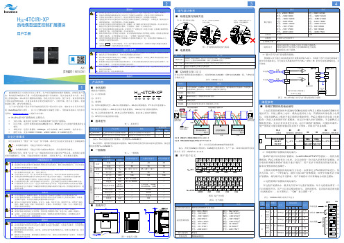
H2U-4TC(R)-XP热电偶型温度控制扩展模块用户手册A01资料编码 19010361客户信息单位地址:单位名称:邮政编码:联系人:联系电话:产品信息产品型号:机身条码(粘贴在此处):代理商名称:故障信息(维修时间与内容):维修人:保修协议◆本产品保修期为十八个月(以机身条型码信息为准。
如有特殊约定,以采购时的合同条款为准),保修期内按照使用说明书正常使用情况下,产品发生故障或损坏,我公司负责免费维修。
◆保修期内,因以下原因导致损坏,将收取一定的维修费用:a ) 因使用上的错误及自行擅自拆卸、修理、改造而导致的机器损坏;b ) 由于火灾、水灾、电压异常、其它天灾及二次灾害等造成的机器损坏;c ) 购买后由于人为摔落及运输导致的硬件损坏;d ) 不按我司提供的用户手册操作导致的机器损坏;e ) 因机器以外的障碍(如外部设备因素)而导致的故障及损坏。
◆产品发生故障或损坏时,请您正确、详细的填写《产品保修卡》中的各项内容。
◆维修费用的收取,以我公司最新调整的《维修价目表》为准。
◆本保修卡在一般情况下不予补发,诚请您务必保留此卡,并在保修时出示给维修人员。
◆在服务过程中如有问题,请及时与我司代理商或我公司联系。
◆客户购买本产品,则说明同意了本保修协议。
本协议解释权归汇川技术。
产品保修卡苏州汇川技术有限公司Suzhou Inovance Technology Co,.Ltd 地址:苏州市吴中区越溪友翔路16号全国统一服务电话:400-777-1260 邮编:215104网址:6785。
发热电缆使用说明书

发热电缆使用说明书使用本产品前,请先阅览此用户手册热电用户手册济南曼格伦电热器具有限公司缆“Man Ge run”加热电缆使用说明书感谢您选择“满格润”产品!在使用本产品前,请阁下(女士)您仔细,完整的阅读本产品的说明书以及其他相关提示。
济南万格润电器有限公司生产的“万格润”采暖电缆低温辐射采暖系统是一套为建筑供暖的系统产品。
因此,在本系统的施工、安装和调试过程中,应严格参照中华人民共和国行业标准jgj142-2022和《地面辐射供暖技术规范》j365-2022的规定。
1.地暖系统施工条件:1)设计图纸及技术方案齐全。
2)施工现场及施工用水、用电等临时设施能满足施工需要:要求场地平整干净,有杂物的要清理干净在施工前清理干净。
地面上保持干燥,无凹凸不平的地方,有水管或线管的应事先在地面上切槽埋入,或将水管或线管沿墙壁排放。
3)有防水层或防潮层要求的地面基层已施工完毕。
4)发热电缆电源引线布线地暖系统中的穿管温控器安装盒已按设计预埋要求完成,确定预埋接线盒已按设计位置埋入,盒内排放有2.5mm2电源线一路,下有一根或几根排线空管通至地面,以供发热电缆冷电源引线及地暖温控器探头线穿入到接线盒内。
现场应有临时用电供安装时使用及安装完毕后通电验收用。
5)铺设区域内其它专业的隐蔽工程已全部完成,现场符合封闭独立施工条件,本单项工程不宜与其它单项工程交叉施工。
2.地暖系统施工程序:1)检查铺设区域确认其符合施工条件。
2)清理铺设区域。
3)铺设绝热保温层。
4)铺设反射层。
5)铺设钢丝网或者直接卡钉固定发热电缆。
6)按设计图纸铺设固定发热电缆。
7)检测发热电缆的标称电阻和绝缘电阻。
8)按要求浇筑混凝土填充层(由建筑装潢施工队完成,此工序不属于电地暖工程范畴)。
9)检测发热电缆的标称电阻和绝缘电阻。
10)安装地暖温控器。
11)铺设地面装饰材料,完成地面施工(由建筑装潢施工队完成,此工序不属于电地暖工程范畴)。
3.地暖系统施工程序,具体操作:1)铺设绝热保温层――挤塑保温板(容重r20kg)铺设前先将场地打扫干净,然后将聚苯乙烯保温板铺设在平整干净的结构面上。
Warmup 电线板暖气说明书

Foil HeatersThis manual contains IMPORTANT information regarding the safe use and installation of your foil heaters. Please read through the entire manual carefully before you install or use the product.Before installing your new Warmup® Foil heater, be sure that you have the following additional parts:• The customized installation plan (or layout) • A Warmup® Thermostat• Digital ohm meter (multi-meter)• 30mA RCD• Electrical Junction box • Electrical conduit •Insulation materialWarmup® Foil mats must be fitted directly on top of the Insulation, and directly under the wood laminate flooring.Before installation always check the subfloor has adequate thermal insulation. This is particularly important where the foil heaters will be used as a primary heat source. A heat loss calculation MUST be carried out to ensure that the product will provide enough heat for your room. See page 7 for information on suitable insulation materials.2Calculate the area of the floor to be heated. This is the total floor area minus any permanent fixtures.Length x width = m ²Select the heating mat or combination of mats closest in size to the area you want to heat. See page 6 for the full range of heater sizes. . Remember Heaters cannot overlapHeaters must be connected in parallelA single thermostat can control up to handle loads up to 16 Amps.DON’T:DON’T use the foil heating mats with glued locking systems or laminatesthat have an underpad or cushion material pre-attached to its underside.DON’T install the foil heater up steps.DON’T install over floors that have traces of moisture, are uneven,have carpets or parquet floor.DON’T l eave insulating materials such as bean bags; linen or towels on the floorsurface.DON’T overlap heating mats, fold or wrinkle the foil heating mats.DON’T place heavy/sharp tools (or any other potentially damaging object) on top of the heating mats.DON’T walk unnecessarily on the foil heating mats.DON’T install mats when the room temperature is below -5ºC.DON’T install foil heating mats anywhere except inside buildings.DON’T i nstall foil mats under walls or partitions, or in areas under heavy cabinets, closets, or fixtures (toilets, sinks, tubs, etc.).DON’T install foil mats within approximately 50mm of any heat conductive buildingpart, such as cold water pipes.DON’T install foil mats within 20mm of one another, 50mm of any wall or 100mm of af ireplace or hot water pipe.DON’T install foil heating mats under wooden floor, if the floor is thicker than 18mm.DON’T use this heater directly under any floor covering other than wood or laminate. DON’T place items on the floor surface which will stop the air flow or not allow heat to rise into the room.DON’T install electrical cables or pipes under the floor with the foil heating mats.DON’T use cellulose insulation.DON’T install the heating mats direct contact with a cement or concrete slab.The heater must be installed on top of a suitable soft Insulation material.3ALWAYS:ALWAYS c heck with the manufacturer of your flooring, that their products are compatible with electric floor heating systems.ALWAYS operate the heating mat with a Warmup® floor sensor thermostat to ensure the floor does not exceed the maximum temperature of the wood laminate(usually 27°C).ALWAYS ensure all earth leads are connected to the earth ring.ALWAYS ensure that the system is operated with a Warmup® thermostat in floorsensor mode.ALWAYS connect all cold wire leads from the foil heating mats in parallelinside an electrical junction box.ALWAYS zone each room with a foil heating system with its own thermostat controller.This allows each room to be controlled individually saving you energy byonly heating the zone when required. Each Warmup® thermostat has amaximum capacity of 16 Amps.ALWAYS ensure that no sharp edges (e.g. metal-edged laminate locking systems)come in contact with the foil heating.ALWAYS install a soft insulation / underlay below the heating mats to preventdamage when the weight of the floor furniture etc is added. Make sureunavoidable wooden floor movements will not harm the foil mats .ALWAYS ensure that a heat loss calculation has been carried out and heatingrequirements have been met if you are using the Foil heating system as aprimary source of heating.ALWAYS ensure that the heaters are protected by a 30mA RCD.ALWAYS ensure that the control card at the back of the manual is completed andfixed at the main consumer unit along with any plans and electrical testrecords. As per the current BS7671 wiring regulations.ALWAYS use the foil strips provided to bridge any gaps when cutting and turning the mats. This is important to keep the earth intact.405Construction:The Warmup® Foil system is constructed using dual core fluoropolymer insulated heating cables sandwiched between two layers of specially reinforced aluminium foil.The aluminium foil along with the uniform spacing of the heating elements ensures even heat distribution. The heating elements are connected to the power supply cable, which exits the mat from one corner.The Foil Heaters must not be installed in thinset cement or in direct contact with acement or concrete slab. The heater must be installed on top of a suitable soft Insulation material . The Warmup® Insulation board may be used if additional levels of insulation are required but a soft underlay will need to be installed on top of the board.If a vapour barrier is to be installed it should be laid below the insulation and not on top of the heater.1. Wood/ Laminate flooring2. Warmup® Foil Heater3. Soft Insulation Material4. Subfloor1. Wood/ Laminate flooring2. Warmup® Foil Heater3. Underlay4. Warmup® Insulation Board5. SubfloorInstallation Examples6Model Area (m 2)Length (m)Width (m)Total Watts Amps Total Resistance WLFH-140W/140120.51400.61377.86WLFH-140W/210 1.530.52100.91251.90WLFH-140W/280240.5280 1.22188.93WLFH-140W/420360.5420 1.83125.95WLFH-140W/560480.5560 2.4394.46WLFH-140W/7005100.5700 3.0475.57WLFH-140W/8406120.5840 3.6562.98WLFH-140W/9807140.5980 4.2653.98WLFH-140W/11208160.51120 4.8747.23WLFH-140W/12609180.51260 5.4841.98WLFH-140W/140010200.51400 6.0937.79WLFH-140W/168012240.516807.3031.49Model Area (m 2)Length (m)Width (m)Total Watts Amps Total Resistance WLFH-80W/80120.5800.35661.25WLFH-80W/120 1.530.51200.52440.83WLFH-80W/160240.51600.70330.63WLFH-80W/240360.5240 1.04220.42WLFH-80W/320480.5320 1.39165.31WLFH-80W/4005100.5400 1.74132.25WLFH-80W/4806120.5480 2.09110.21WLFH-80W/5607140.5560 2.4394.46WLFH-80W/6408160.5640 2.7882.66WLFH-80W/7209180.5720 3.1373.47WLFH-80W/80010200.58003.4866.13140W80WPlease ensure that your laminate flooring is suitable for use with electric underfloor heating.Most wood / laminate floors are compatible with the Foil mats but we do not recommend using any wood flooring thicker than 18mm.Wood flooring with metallic strips as part of their locking systems are NOT compatible as these metallic strips may damage the Foil mats.Any wood floor with a pad already attached must not be used with the Warmup® Foil mats.For a wooden floors or similar the thermal resistance should not exceed 0.15m ²K/W.TopBottomThe Foil Heaters MUST NOT be installed in thinset cement or in direct contact with a cement or concrete subfloor. The heater MUST be installed on top of a suitable soft Insulation material. ThisAs with all electrical projects which are subject to Part P , all electrical work must be carried out by a certified electrician. All work must conform to the current IEE wiring regulations - BS7671.The system must be protected by a dedicated 30mA RCD at all times. For systems not exceeding 13 amps a fused spur or 30mA RCD/spur that has contact separation in all poles that pro-vides full disconnection under over-volt-age category III conditions must be used.For systems larger than 13 amps a suitable protective device that meets the current wiring regulations must be used.Connecting the thermostatThe thermostat should be installed in the room to be heated. In the case of bath-rooms or wet areas a electrician should be consulted regarding whether a suitable zone is available.The thermostat can handle a load up to16 amps. For larger installations exceeding 16 amps multiple thermostats may be required or it may be possible to use a Contactor.Once all of the connections have been made, the electrician must complete the relevant forms and display at the fuse board as per BS7671, Section 753.8A resistance tests should be carried out on the heating mat before, during and after fitting the final floor covering.Using a Multi-meter set at 2K ohms test across • Live to neutral = ohms value as listed on Page 6If you do not get the expected results or at any time you believe there may be a problem, please contact Warmup’s Technical Team for guidance.Record the readings on the control card at the back of the manual.NOTE: Ensure that the floor sensor is tested before the final floor finish has been laid. The floor sensor values can be found in the thermostat instructions. When testing the floor sensor ensure that the meter can read up to 20k ohms.Before installing, draw an installation plan showing the placement of the mats, floor sensor, and junction box or boxes.The Foil heating mats should cover at least 80-90% of the floor area of your room to be used as a primary heat source*.Choose the combination of heating mats that best enables you to cover the recommended 80-90% of your room. Plan to use the larger foil heating mats as much as possible and to use smaller mats only as gap fillers.Note: The mats are supplied with a 3 metre long electrical cold lead. If you need longer connection leads, these may be extended consult a qualified electrician.*Depending on insulation, air-flow & overall heat-loss within the room, additional heating may be required.It is important to keep an accurate record of where the mats are installed.The Foil heater MUST NOT be installed in thinset cement, or indirect contact with a cement or concrete subfloor.There must always be a soft insulation / underlay beneath thealuminium heating mats.Carefully inspect the subfloor and make sure it is clean, free ofsharp edges, protruding nails and any other materials that maydamage the heating mat.Lay the Insulation as per the manufacturer instructions.If you are using the Warmup® insulation board you will need toinstall a soft underlay on top of the boards.Remove the foil heating mat from the packaging and check themats visually for any damage.Test using a multi-meter and verify the correct resistance againstthe table on page 6. Record the readings on the control card at theback of the manual.910Roll out the foil heating mats on top of the insulation material. Keep the heating mat at least 50mm from the edges of the room. Ensure that the heating mat is completely flat. Care should be taken not to fold or crease the mats at any time during installation.Position it in such a way that the power cord will be able to reach the point where the thermostat will be connected.If fitting more than one foil heating mat ensure that the mat does must not overlap, as overheating will result. Leave a gap of at least 20mm between each mat. Secure the foil mat to the underlay using tabs of duct tape to hold the mat in position.If any of the wire has been detached from the foil mat (when the mat is cut and turned) the wire MUST be covered by the aluminium strips. The aluminium strips should also be used to bridge the gap between the sections of the mat.NOTE: This is essential in order to keep the earth circuit intact.Secure the mats to the floor with tabs of duct tape. Since the joint and the cold tail leads are slightly thicker than the rest of the mat, you will need to create a slight groove in the insulation to ensure the heating mat lays flat. Do not allow the power supply cable to cross or come into contact with the heating mat.Once the heater(s) have been laid mark each pair of coldtail leads coming from the same mat with a numbered sticker This will make it easier to identify each mat once the floor coveringis laid.Position the sensor approximately 300mm into the heated area in-between the heating wires runs on the mat.Do not allow the sensor tip to come into contact with any of the heating element wires.Warmup recommend the use of conduit when installing the floor sensor. The conduit will protect the sensor and will allow for easier replacement should there be a problem after flooring has been laid.Run the sensor cable back to the thermostat. The sensor wire MUST not cross over the foil heater wires.Test the floor sensor using a multi-meter. The floor sensor ohms reading values can be found in the thermostat instructions.11Before fitting the final floor covering test the heating mats to ensure that they have not been damaged during installation. See page 8 for details.You are now ready to lay the final floor finish. Take care not to damage the heating mats. Do not drive nails or screws into the floor or cut the floor panels on top of the heater.If the floor is not being laid immediately, all heating mats must be protected with cardboard to prevent damage. Immediately prior to the floor being laid, test the heating mat to ensure it has notbeen damaged.Once the flooring has been installed, connect the thermostatensuring that it is set to reach a maximum temperature of 27°C.A Warmup® thermostat with a floor sensor MUST be used inorder to accurately monitor the floor temperature and yourcomfort level.Always zone each room with a foil heating system with its ownthermostat controller. This allows each room to be controlledindividually saving you energy by only heating the zone whenrequired.WARNING:ELECTRICAL WORK WHICH IS SUBJECT TO PART P BUILDING REGULATIONS MUST BE CARRIEDOUT BY A QUALIFIED ELECTRICIAN.ALL WORK MUST CONFORM TO THE CURRENT IEE WIRING REGULATIONS.1213Register your Warmup ® Warranty online at Warmup ® Foil Heater is guaranteed by WARMUP PLC (“Warmup”)to be free from defects in materials and workmanship under normal use and maintenance, and is guaranteed to remain so subject to the limitations and conditions described below.The Warmup® Foil Heater is guaranteed for 15 Years from the date of purchase against manufacturing defects. The 15 year guarantees applies:1. Only if the unit is registered with Warmup within 30 days after purchase. Registration can be completed online at . In the event of a claim, proof of purchase is required, so keep your invoice and receipt - such invoice and receipt should state the exact model that has been purchased ; and2.Only if the heater has been earthed and protected by a 30mA RCD at all times. Thermostats are guaranteed for a period of 3 YEARS from the date of purchase.Neither guarantee continues if the floor covering over the heater(s) is damaged, lifted, replaced,repaired or covered with subsequent layers of flooring.This guarantee period begins on the date of purchase. Registration is confirmed only when confirmation is sent by Warmup PLC.During the period of guarantee Warmup will arrange for the heater to be repaired or (at its discretion) have parts replaced free of charge. The cost of repair or replacement is your only remedy under this remedy under this guarantee which does not affect your statutory rights. Such costs does extend to any cost other than direct costs of repair or replacement by Warmup and does not extend to costs of relaying or repairing any floor covering or floor.If the heater fails due to damage caused during installation or tiling, this guarantee does not apply. It is therefore important to check that the heater is working (as specified in the installation manual) prior to installing the final floor finish.WARMUP PLC SHALL IN NO EVENT BE LIABLE FOR INCIDENTAL OR CONSEQUENTIAL DAMAGES, INCLUDING BUT NOT LIMITEDTO EXTRA UTILITY EXPENSES OR DAMAGE TO PROPERTY. Terms and conditions applyREGISTER YOUR HEATER ONLINE AT: THE 15- YEAR ELEMENT OF THIS GUARANTEE DOES NOT EXTEND TO THERMOSTATS WHICH ARE COVERED BY A 3 YEAR GUARANTEE. THIS GUARANTEE DOES NOT AFFECT YOUR STATUTORY RIGHTS.Warmup PLC is not responsible for : 1. Damage or repairs required as a consequence of faulty installation or application. 2. Damage as a result of floods, fires, winds, lightning, accidents, corrosive atmosphere or other conditions beyond the control of Warmup PLC. 3. Use of components or accessories not compatible with this unit. 4. Products installed outside the United Kingdom. 5. Normal maintenance as described in the installation and operating manual. 6. Parts not supplied by Warmup.7. Damage or repairs required as a result of any improper use, maintenance, operation or servicing. 8. Failure to start due to interruption and /or inadequate electrical service. 9. Any damage caused by frozen or broken water pipes in the event of equipment failure. 10. Changes in the appearance of the product that does not affect its performance. SafetyNet TM Installation Guidelines : If you make a mistake and damage the new heater before laying the floor covering, return the damaged heater, to Warmup within 30 DAYS along with your original dated sales receipt. WARMUP WILL REPLACE ANY HEATER (MAXIMUM 1 HEATER) WITH ANOTHER OF THE SAME MAKE AND MODEL-FREE.PLEASE NOTE: 1. Repaired heaters carry a 5 year warranty only. Under no circumstances is Warmup responsible for the repair or replacement of any flooring.2. The SafetyNet TM Installation Guarantee does not cover any other type of damage, misuse, or improper installation due to improper adhesive or subfloor conditions. Limit of one free replacement heater per customer or installer. 3.Damage to the heater that occurs after laying the floor covering is not covered by the Safety Net TM Installation.Guarantee.14This form must be completed as part of the Warmup Guarantee. Ensure that the values are as per the instruction manual.This card must be situated close to the consumer unit in a visible place.Note: Draw a plan showing the layout of the heater.Warmup plc, 702 Tudor Estate, Abbey Road, London, NW10 7UW T: 0345 345 2288 F: 0345 345 2299 0The WARMUP word and associated logos are trade marks. © Warmup Plc. 2021 - Regd. TM Nos. 1257724, 4409934, 4409926, 5265707. E & OE.Warmup plc n 704 Tudor Estate n Abbey Road n London n NW10 7UW n UK Warmup GmbH n Ottostraße 3 n 27793 Wildeshausen n DE Warmup plc ************* Tel: *********** Fax: ***********Warmup - IM - WLFH_Foil Heater - V2.6 2021-06-18_EN。
热流道控制器用户使用说明书

热流道控制器用户使用说明书产品使用前,请仔细阅读说明书,以便正确使用,并妥善保存,以便随时参考。
断电后方可清洗仪表。
清除显示器上污渍请用软布或棉纸。
显示器易被划伤,禁止用硬物擦拭或触及。
禁止用螺丝刀或书写笔等硬物体操作面板按键,否则会损坏或划伤按键。
1.在使用前先检查控制器⑴检查控制器的配件是否齐全⑵检查电源是否安全受控⑶检查此说明书是否与控制器匹配⑷检查连接器是否安全可靠⑸检查加热器是否安全可靠⑹检查主电源是关闭的⑺检查电源是否适合控制器的工作⑻确定地线连接控制器⑼打开主电源开关⑽打开各个控制器工作开关⑾设定控制温度⑿检查控制器是否达到设定温度,且稳定2. 控制器输出⑴PID控制通过测量实际温度和设定温度进行比较,精确计算比例、微分、积分值,控制输出电压⑵自整定通过分析加热器和加热模式排除环境变化调整控制参数⑶输出模式根据电源环境确定●50赫兹●60赫兹3. 技术参数输入电压:AC 85V-250V,50/60HZ,15A负载能力:15A,150W-1650W(110V),100W-3300W(220V)输出类型:PWM传感器:热电偶(K \ J)温度范围:100℃~400℃温度稳定性:±0.5%温度控制类型:PID 控制环境温度:-10℃~50℃4.面板布局1.指示灯:状态指示灯(STATE):软启动常亮,预整定1秒闪烁,自整定0.5秒闪烁,其他状态不亮。
输出指示灯(OUT):指示输出的的状态。
自动指示灯(AUTO):指示自动模式被选择。
等待指示灯(STANDBY):指示等待模式被选择。
手动指示灯(MANUAL):指示手动模式被选择。
2.数码管:PV数码管,红色,显示测量温度和参数代码。
SV数码管,红色,显示设定值和参数代码值。
3.按键::输入键:模式键:AUTO、STANDBY、MANUAL模式转换键:增加键:减小键5.操作模式通过按SEL键1秒钟以上可以进入以下模式。
⑴自动模式:正常的PID控制,在正常的设定值上。
AEULO发热电缆安装技术手册

AEULO发热电缆安装技术手册北京埃斯沃科技进展有限公司目录埃沃AEULO 发热电缆地温辐射供暖系统一、系统概述埃沃AEULO 发热电缆低温辐射供暖系统二、系统介绍1、发热电缆低温辐射供暖系统的工作原理及组成2、埃沃AEULO 发热电缆低温辐射供暖系统的要紧优点3、埃沃AEULO 发热电缆低温辐射供暖系统的运行费用分析4、发热电缆低温辐射供暖系统的功能特点5、几种采暖方式的综合比较6、发热电缆低温辐射供暖方式的不足7、采纳发热电缆低温辐射供暖方式应注意的咨询题8、发热电缆供暖系统的应用范畴三、发热电缆低温辐射供暖系统设计指南1、设计标准和依据2、设计实例四、温度操纵设计1、温度方案选择2、温控器型号选择五、要紧辅材1、绝热层2、反射层3、钢丝网4、电缆固定材料5、填充层6、穿管材料六、电气设计1、设计依据2、设计讲明3、电气设计步骤4、低压配电设备的选型5、配电线路的设计6、电路操纵形式图图例七、施工安装与调试1、施工条件2、施工程序3、施工方法4、系统运行调试5、发热电缆的爱护6、关于实木地板铺设发热电缆的施工要求埃沃AEULO 发热电缆--管道保温系统一、系统特点二、应用范畴三、设计指南1、确定热负荷2、电缆选型3、系统设计四、安装指南1、安装要点2、安装程序埃沃AEULO 发热电缆--道路化雪系统埃沃AEULO 发热电缆--屋檐、天沟化雪系统埃沃AEULO 发热电缆-- 土壤加热系统埃沃AEULO 发热电缆-- 卫生间用发热电缆系统埃沃AEULO 发热电缆地温辐射供暖系统一、埃沃AEULO 发热电缆低温辐射供暖系统概述埃沃AEULO 发热电缆低温辐射供暖系统是以电力为能源、发热电缆为发热体,将100%的能源转换为热能,通过采暖房间的地面(或墙面、顶面)以温热辐射的形式,把热量送入房间。
传导、对流和辐射三种热量传递方式中人们对热辐射的感受最为良好,因此,发热电缆低温辐射供暖系统是 世界暖通工程界公认的最理想、y节能、谬施工、可实现分时操纵、投资费用低、治理方便、二、发热电缆低温辐射供暖系统介绍1、 发热电缆低温辐射供暖系统的工作原理及组成 1.1工作原理发热电缆低温辐射供暖系统的工作原理是发热电缆通电后,工作 温度为40〜60C ,通过地面(或墙面、顶面)作为散热面,以少部分对流换 热加热周围空气的同时,大部分热量向四周的围护结构、物体、人体以辐 射方式传递,围护结构、物体和人体吸取了辐射热后,其表面的温度升高, 从而达到提升并保持室温的目的。
Omega Engineering 产品说明书:热带电缆与预设温度器

Immediate hazards which WILL result in severe personal injury or death
Hazards or unsafe practices which COULD result in severe personal injury or death
Width inches
1 1 1 1 1
Length inches
24 48 72 96 120
Total Watts 104 209 313 418 522
Part Number 120VAC
HTWT101-002-60F HTWT101-004-60F HTWT101-006-60F HTWT101-008-60F HTWT101-010-60F
• Never handle the heating tape while it is in operation; always disconnect the heating tape from the power source and allow to cool prior to handling.
heaters. • Do not crush or apply severe physical
stress on heater or cord assembly. • Unplug heater when not in use. • Make sure there is a uniform fit prior
• The end-user is responsible for providing suitable overprotection device. It is highly recommended that a ground fault circuit breaker be used.
应用指南 - AMSC AC 高温超导电缆说明书

Applica'on Guide for AC High Temperature Superconduc'ng (HTS)CablesFebruary 5th, 2020©AMSCLEGAL NOTICEThis Applica'on Guide for HTS Cable systems was prepared by AMSC. Neither AMSC, its subsidiaries, nor any person ac'ng on behalf of either:1. Makes any warranty or representa'on, express or implied, with respect to the use of any informa'on contained in this document, or that the use of any informa'on, apparatus, method, or process disclosed in the report may not infringe privately owned rights; or2. Assumes any liabili'es with respect to the use of or damage resul'ng from the use of any informa'on, apparatus, method or process disclosed in this document.Document Revision HistoryRevision #Date Descrip'on By 0119FEB2020Ini'al Release MRIntroduc'onPurposeThis Applica'on Guide is intended for use by power system planning engineers, consultants and those in related fields, to gain a high level understanding of the applica'ons and modeling of AC High Temperature Superconduc'ng (HTS) Cables for applica'ons on u'lity scale power systems. This guide should be helpful for studies using power system simula'on soRware such as PSS/e, PSLF, DigSILENT, PowerWorld, PSCAD and similar packages.Any user of this Applica'on Guide should feel free to contact AMSC at any 'me for addi'onal guidance and support on aspect of studying applica'ons of HTS cable. Contact informa'on is provided at the end of this document.This Applica'on Guide is NOT intended for applica'ons of DC HTS Cables, industrial/commercial applica'ons, or transporta'on/military applica'ons. The level of detail provide is sufficient for simula'on accuracy on the order of cycles (i.e. 10’s of mS) in phase-domain type simula'ons. In 'me-domain simula'ons, the approaches presented are reasonable for RMS type results, but are not sufficient for sub-cycle, “waveform” type simula'ons such as EMTP or PSCAD.Please contact AMSC regarding applica'ons and levels of accuracy outside that discussed above. Technology OverviewThe key characteris'cs of HTS cables, from the perspec've of power system modelling, that differen'ate the cables for tradi'onal copper or aluminum cables are:1)High Ampacity2)Zero Resistance3)Low Inductance4)Fault Current LimiDngThe primary characteris'c of superconductor cables is the ability to carry very high levels of current at zero resistance. In general, the ampacity of the cables is limited more by ancillary equipment (breakers, bus bars, etc.) than the cables themselves. Many u'li'es assume the cables at 3000A maximum current, as that is the maximum breaker ra'ng they typical procure, but cable designs up to 5000A are available.The cables have zero resistance, rela'vely low inductance and comparable capacitance to conven'onal cables. This document provides guidance on R, X and B values for modeling.HTS Cables have “Fault Current Limi'ng” characteris'cs in the resistance of the cable, which changes from near zero, to a rela'vely high value in the event that the cable is exposed tocurrent levels above the cable’s ra'ng, such as during fault events. This change in resistance is u'lized to manage fault current levels through the cable. While the mechanics/physics of this characteris'c is outside the scope of this document, this document does provide guidance on how to correctly model the cable during fault condi'ons to capture this characteris'c. Please contact AMSC if more informa'on is desired regarding this feature of the cables.Other advantages of HTS cables that are important to the si'ng and installa'on of the cables, but are not necessarily important to the soRware simula'on and modeling of the cables are:A)High power density (i.e. small cross-secDonal area)B)Thermal IsolaDon (no heat emiJed from cables)C)Nearly undetectable Electro-MagneDc Fields (near zero EMF)D)Simplified PermiSngThe small size and lack of heat or EMF signatures are extremely helpful in the si'ng, permieng, civil works, and installa'on of the cables. From an applica'on / planning perspec've this is important in that the cables can be installed in places where conven'onal cables are not typically allowed (i.e. thermally limited duct banks, deep direc'onal bores, across bridges, etc.), however these characteris'cs do not directly impact the modeling of the cables and therefore are not heavily discussed in this document.Applica'on OverviewDue to the high ampacity and compactness of HTS cables, the primary u'lity applica'on of the cables is as a distribu'on voltage alterna've to transmission cables in urban (or otherwise space constrained) areas. This is because a distribu'on voltage HTS Cable can, in many cases, carry as much power as a transmission voltage cable. The characteris'c creates several sub-applica'on op'ons discussed in detail in this document.Other applica'ons include the replacement of many conven'onal cables with a much smaller number of HTS cables (allowing for smaller Rights-of-Way), overcoming thermal and geographical limita'ons (i.e. substa'on get-a-ways, thermally limited duct banks, direc'onal drilling under rivers/highways), and undergrounding of overhead circuits.Primary Applica'onsTransmission Power at Distribu'on VoltagesThe primary applica'ons of HTS cables take advantage of the ability of the technology to move bulk, transmission level power at distribu'on voltages because of their ability to carry high levels of current. The figure below assumes a maximum XLPE cable ampacity of 1000A (high end of typical range) and an HTS cable ampacity of 4000A (maximum commercially available non-gas insulated switchgear ra'ng).From a planning perspec've, this capability allows for three major applica'ons of HTS cables:1)Loop Applica'ons for Reliability/Resiliency ImprovementHTS cables have applica'ons that increase the reliability and resiliency of service to one or more substa'ons in urban power systems. This is generally achieved by “looping” the substa'ons together with HTS cables at the distribu'on voltage level such that the HTS cables behave as a “back-up” to the transmission system.This approach is effec've because in the event of an N-1 to N-4 type loss of transmission or transforma'on serving the load at one or more of the substa'ons, power can be transported from substa'on to substa'on via the HTS cable system; effec'vely crea'ng redundancy.This is possible in part because most urban substa'ons already have redundancy in transforma'on (typically N-1 to N-2). This applica'on of HTS cable effec'vely makes the spare transforma'on at the various sta'ons “fungible” in that the spare transforma'on at one sta'on can be u'lized to serve load at another, in the event of outage condi'ons.In another varia'on on this applica'on, addi'onal spare transforma'on could be installed at one substa'on, but u'lized (via the HTS cables) at one or more other substa'ons, helping to overcome space constraints and crea'ng strategic and opera'onal flexibility.The fault current limi'ng aspects of the HTS cables are important to this applica'on as without that feature modelled properly, the fault current levels at the interconnected substa'ons may rise to unacceptable levels.It should be noted that as this approach u'lizes the HTS cables for “back-up” or redundant purposes, meaning that the HTS cables can be placed out of service during “system normal” condi'ons. This may be recommended even in scenarios without fault current concerns as the cables may cause undesirable “loop flows” if closed in during normal condi'ons. In such cases, the cables are oRen placed into service following N-1 outage events to increase resiliency in the event of a second and subsequent outages.If simula'ons show elevated fault current levels for desired applica'ons and condi'ons even when the Fault Current Limi'ng aspects of the cable are modelled properly, this situa'on can typically be resolved with the addi'on of conven'onal reactors installed in series with the cables.That this applica'on is generally akrac've as an alterna've to improving reliability and resiliency in urban areas via conven'onal means, such as addi'onal transmission circuits and/or new or expanded substa'ons, which are extremely costly, difficult to permit and disrup've and 'me consuming to construct.2)Branch Applica'ons for Capacity IncreasesHTS cables can also be applied to increase capacity at exis'ng substa'ons or serve as the primary source to new substa'ons. Common configura'ons in this scenario involvedistribu'on voltage HTS cables effec'vely replacing transmission voltage conven'onal cables as the means to move bulk power to the new or expanded substa'on, which eliminates the need for new transforma'on (and any transmission voltage equipment) at that substa'on.This approach requires sufficient transforma'on at the substa'on(s) that serves as the source to the new or expanded substa'on and may require the installa'on of addi'onal transformers. This applica'on is generally considered if 1) the new/expanded substa'on is space constrained, and/or 2) the cable route (ROW) between the source substa'on and the new/expanded substa'on is space constrained or otherwise is not well suited for transmission voltage cables (for permieng, safety, or constructability, or other reasons). It is helpful to think of this applica'on as crea'ng “flexibility” in the loca'on of new transforma'on (i.e. new transformers can be located where there is sufficient space) with the HTS cables serving the func'on of a extend “bus” to the load substa'on. Consider the applica'on in the figure below:Image credit: Nexans S.A.The applica'on of an HTS cable described in the figure above (Ampacity project, Essen, Germany, commissioned in 2014) shows a scenario where increased capacity is desired at the urban Substa'on Dellbrugge, with that capacity to be served from the suburban Substa'on Herkules. The conven'onal solu'on would have been to run a 110kV transmission cable from Herkules to Dellbrugge and install a new transformer at Dellbrugge. However, Dellbrugge is severely space constrained and the addi'on of a new transformer would be prohibi'vely costly. The HTS cable (10kV, 2310A, 40MVA) instead allows the new transformer to be installed at Herkules (which is not space constrained) and brings the new power to Dellbrugge at the localdistribu'on voltage (10kV), removing the need to install large equipment at Dellbrugge and simplifying the permieng and cost of the new cable ROW.3)HPFF Cable Backup/Replacement for System Moderniza'onHTS cables can be applied to assist in the transi'on away from High Pressure Fluid Filled (HPFF or “Pipe-Type” cables). HPFF cables technology is rapidly becoming obsolete in the u'lity industry primarily due to the poten'al environmental hazards they create (oil spills) and a single manufacturer of such cables remains ac've. Many u'li'es that currently have HPFF cables deployed on their systems are in the process of developing strategies to eventually decommission and remove these cables from service.This effort presents challenges because HPFF cables are rela'vely current dense and replacing the cables with conven'onal XPLE cables without either 1) reducing ampacity or 2) substan'al civil works can be challenging. Furthermore, HPFF cables represent a cri'cal and substan'al part of many urban transmission networks, and the 'me required to replace the cables create extended dura'on con'ngency scenarios that can threaten the reliability of the system.HTS cables can be applied in these projects in two possible ways. One applica'on is to directly replace the HPFF cables with HTS cables using the exis'ng HPFF pipes. Because HTS cables have an even higher current density than HPFF cables, this approach may increase the ampacity of the circuit. However, this approach does not eliminate the risk to the system during the 'me it takes to replace the HPFF cables with the HTS cables, as well as the risk of the HTS cables to physically fit within the exis'ng pipes.Another applica'on is to install distribu'on voltage HTS cables in parallel with the exis'ng transmission voltage HPFF cables. This approach allows the HTS cables to act as a distribu'on voltage (but equivalent power level) “back-up” to the exis'ng cable, similar to the “Loop Applica'on” discussed earlier. This approach does require the civil construc'on of new cable ducts and possibly new Right-of-Way (RoW) for the HTS cables. However, this approach allows for construc'on and installa'on to occur without taking the HPFF cables out of service, allows for the con'nued u'liza'on of the HPFF cables, allows for a deliberate transi'on from HPFF cables to the HTS cables, and preserves the HPFF cable pipes for alterna've uses such as XLPE cable replacement without significant civil works (albeit with a lower ampacity than the original HPFF cables). Furthermore, it is very likely that such an HTS cable approach would be lower cost and less disrup've than full scale replacement of the HPFF cables with larger cable ducts to allow for similar or higher ampacity XLPE cables.Modeling HTS Cables in Power System Simula'on SoZwareAs discussed earlier, the key considera'on with the modeling of HTS cables is capturing the change in impedance of the cable during fault condi'ons (i.e. the Fault Current Limi'ng feature). This characteris'c is a fundamental difference between HTS cables and conven'onal copper or aluminum cables. The mechanics/physics that are the cause of change of impedance of HTS cables are outside the scope of this document, but the following items should be noted:1)The impedance of the HTS cables is unchanging as long as the current through thecable is below the rated current of the cable (e.g. 3000A).a.For load-flow simula'on work that does not consider fault condi'ons, theimpedance changing characteris'c of the cable can be ignored, whichsignificantly simplifies the cable model.2)For the purposes of phase-domain simula'ons (i.e. PSS/e, PSLF, PowerWorld, Cyme,etc.) the change of impedance of the HTS cables is effec'vely instantaneous upon the current in the cable exceeding the ra'ng of the cable (i.e. upon fault ini'a'on), andreturns to the original value instantaneously upon fault clearing, assuming normalprimary or backup fault clearing.a.There is no 'me delay between fault ini'aliza'on/clearing and the impedancechange; both events should occur in the same 'me step.3)In the event that a system fault is causing fault current to flow through the HTS cablefor longer than normal backup clearing dura'ons (i.e. simula'on of events moresevere than typical breaker failure events), the cable will trip offline.4)The modelling techniques discussed below are NOT appropriate for detailed, 'me-domain simula'ons, such as PSCAD or 'me-domain DigSILENT simula'ons, if accuracy in RMS current flow and wave forms through the cables are cri'cal to the simula'on results during and shortly (1 cycle) aZer fault events.The figure below describes the model of an HTS cable, subject to the comments above:The model described above shows that the cable is modelled with single, unchanging values for Inductance (reactance) and Capacitance (charging), but with two parallel branches for resistance. The resistance branches are 1) the near zero “superconduc'ng resistance” (Rs) and 2) the rela'vely large “Quenched Resistance” (Rq).The model is operated by having all components “in-service” during the normal case. During this scenario, the value of Rs is much lower than Rq causing near zero current flowing through Rq, resul'ng in a near zero-resistance circuit (but s'll featuring Inductance and Capacitance). When a fault is placed on the system, the switch in the Rs branch is opened (i.e. taken out of service or changing the resistance to an extremely high value), forcing all current through Rq,effec'vely represen'ng the cable resistance when “quenched” or non-superconduc'ng.When the fault is cleared from the system, the switch in the Rs branch is re-closed (i.e. placed in-service or changing the resistance to the original near-zero value), returning the circuit to the original, pre-fault resistance.The Inductance and Capacitance of the cable should be modelled using the typical circuit modelling approach available in the modelling package being used, except with zero resistance. For most packages, the capacitance is split into two halves, with each half located on either end of the circuit as shown above (“B/2”). Other generally accepted approaches to modeling capacitance are acceptable.To determine the actual value of the parameters (Rs, Rq, X & B), it should be noted that there are two primary configura'ons of HTS cables: Cables that are 36kV and below use a “tri-axial” configura'on, whereas cables of 69kV and above use a more conven'onal “one cable per phase” configura'on. The configura'on impacts the inductance and capacitance values, but does not impact the resistance values (Rs or Rq).The table below provides typical values for the cable parameters in ohms, mH, and uF per kilometer:MulDply values above by 1.609 for values per mileFor reference, the table below converts the parameters to units commonly used in PSS/e (p.u. on 100 MVA base), for various base voltage levels. MulDply values above by 1.609 for values per mileThe values above are typical and representa've for 3000A cables. The Rq value, in par'cular, may vary significantly and can be specified to a point.p.u. X on 100 Charging kVAR of p.u. B on 100Voltage (kV L-L)MVA Base R superconducting R quenched Current (A)Charging MVA base 12.470.01188 6.43E-050.466 2.9921.50.00021513.80.00970 5.25E-050.380 3.3026.30.000263260.00273 1.48E-050.107 6.2293.40.00093434.50.001558.40E-060.06088.261650.00165690.000475 2.10E-060.0152 3.001200.001201150.0001717.56E-070.00547 5.013320.003321380.000119 5.25E-070.00380 6.014790.004791610.0000873 3.86E-070.002797.016510.006512300.0000428 1.89E-070.0013710.013300.01333450.00001908.40E-080.00060815.029910.0299p.u. R on 100 MVA Base PSSE Inputs, per kmHTS Cable ParameterValue Unit X (<= 36kV)0.049mH/km X (>= 69kV)0.06mH/km R superconducting0.0001ohm / km R quenched0.724ohm / km C (<= 36kV)1.1uF/km C (>= 69kV)0.2uF/kmPlease contact AMSC for details and any further ques'ons.QUESTIONS?Please Contact AMSC:Michael Ross*********************+1-608-320-5693。
- 1、下载文档前请自行甄别文档内容的完整性,平台不提供额外的编辑、内容补充、找答案等附加服务。
- 2、"仅部分预览"的文档,不可在线预览部分如存在完整性等问题,可反馈申请退款(可完整预览的文档不适用该条件!)。
- 3、如文档侵犯您的权益,请联系客服反馈,我们会尽快为您处理(人工客服工作时间:9:00-18:30)。
Top brands from Germany
感谢您选用本产品 安装使用本产品前, 请仔细阅读本手册
埃沃AEULO电地暖用户手册
北京埃斯沃科技有限公司
网址:www.aeulo.com
埃沃AEULO
感谢您选用:埃沃AEULO发热电缆及其它电地暖 产品。为了确保提供完善的售后服务,请您 认真阅读本手册,填写相关手册并妥善保存。
●埃沃AEULO发热电缆不可随意裁剪
埃沃AEULO
施工使用埃沃AEULO发热电缆电地暖系统,请严格按照 遵照本手册安装使用的基础上,埃沃AEULO产品保证书才 埃沃AEULO发热电缆质保期20年,使用寿命50年,温
埃沃AEULO
埃沃AEULO
埃沃AEULO 17
埃沃AEULO 18
保护电流:30mA
埃沃AEULO
埃沃AEULO
埃沃AEULO
铺设铁丝网
按设计图纸铺设埃沃 AEULO发热电缆
埃沃AEULO
埃沃AEULO
埃沃AEULO
埃沃AEULO
埃沃AEULO
品质保证
埃沃AEULO电缆每一根都经过了严格的检测程序 埃沃AEULO发热电缆质量保证期为:20年 埃沃AEULO全力打造地暖顶尖品牌。
埃沃AEULO发热电缆及电地暖在施工、安装、调试过
JIN埃G沃KAEUULNO
AEULO发热电缆结构
2
3
1---发热体:多股高熔点合金发热丝 1
2---回路线:1.0mm2多股镀锡铜线
3---抗拉体:高强度防抗拉材料
4
5
4---绝缘体:耐高温辐照交联材料
5---绝缘体:耐高温辐照交联材料
6---保护层:PET聚酯薄膜
感谢您选用:埃沃AEULO发热电缆及其电地暖产品。 埃沃AEULO发热电缆安全舒适、经久耐用、品质卓越。
埃沃AEULO
建议发热电缆与埃沃AEULO 专用智能温控器配套使用。
AEULO
AEULO
埃沃AEULO
使用埃沃AEULO发热电缆首次运行
埃沃AEUL0电地暖系统使用建议
埃沃AEULO
●埃沃AEULO发热电缆铺设区域内,严禁穿凿、钻孔、进行 射钉作业;
7---接地线:镀锡铜绞线(1.0mm2)
7Hale Waihona Puke 68---屏蔽层:铝箔复合体(阻抗0.1Ω/m)
9---外护套层:耐高温聚氯乙烯,壁厚大
于0.8mm
8 AEULO发热电缆技术参数
AEULO
工作电压:220VAC
输出功率:20W/m
9
直径:φ7.1mm
最高表面温度:95℃
测试电压:4000V
抗拉力:900N