无线手轮修改轴选说明书
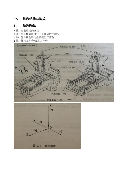
牧野Professional5使用说明书摘要(a1系列 a51 a61 a71 a81 a82 a92卧式加工中心)
B 其他 NC 功能开关(主操作盘上能够设定的功能) 下列功能在主操作盘上没有配置,可以在功能画面上操作,也可以利用柔性开关功能进
B NC 程序的启动/停止
循环[START]开关 按下该开关,启动 NC 程序。在 NC 程序启动过程中,白色指示灯灯亮灯。在 MDI、 存储器、DNC 运行、磁带模式下有效。
[FEED HOLD]开关 按下该开关,停止 NC 程序。在 NC 程序停止的过程中,白色指示灯灯亮灯。如果 按下该开关则会变成进给暂停状态。但是,M、S、T 功能仍继续动作,直至结束后 才停止。 即使在进给暂停的状态下,下列动作仍然能够继续: 主轴旋转 刀具自动更换(ATC) 托盘自动交换(APC) 供给切削油 部分固定循环
主轴锥孔 快速进给速度 切削进给速度
高度 质量
X 轴*Y 轴*Z 轴 作业面的大小 最大承载质量 主轴旋转速度
主轴锥孔 快速进给速度 切削进给速度
高度 质量
X 轴*Y 轴*Z 轴 作业面的大小 最大承载质量 主轴旋转速度
主轴锥孔 快速进给速度 切削进给速度
高度 质量
13100kg(刀具 40 把)
730*730*800m □630mm 1200kg
A 标准规格设备的主操作盘上所配备的开关
[SINGLE BLOCK]开关 将单程序块模式置于有效/无效。如果但程序块模式置于有效,程序则每执行完 一个程序块就会停止。
[BLOCK SKIP]开关 将程序块跳跃模式置于有效/无效。如果程序跳跃模式被置于有效时,在程序 中,初始部分含有[/](斜线)的程序块将被忽略。
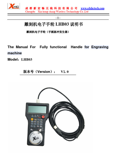
LHB03有线电子手轮说明书
Button
implementation machine
X 分中按钮
将 X 工件坐标分中
X Coordinates 1 / 2 X Coordinates 1 / 2 Button
Y 分中按钮
将 Y 工件坐标分中
Y Coordinates 1 / 2 Y Coordinates 1 / 2 Button
成 都 新 宏 畅 无 线 科 技 有 限 公 司 Chengdu Xin hong chang Wireless Technology Co.,Ltd
-3-
鼠标双击图标,开始安装驱动 Double click the icon to begin installing the driver
breakpoint
浮 动 对 刀 开 始 / 停 止 当按下该键,机床执行对刀操作:同时,YES 和 NO 提示
按钮/复位按钮
灯闪烁,需要用户再次确认是否需要进行对刀。如果按下
YES 键,则开始对刀,LCD 的对刀图标闪烁;表示正在进 Floating on the knife
行对刀操作。按下 NO,则退出对刀。 start or stop or reset
Button
当机床处于加工运行状态下,按下该按钮,机床复位,停止
加工
When you press the button, the machine Operating the knife
YES and NO LED flashing lights, requires the user to reconfirm the need for the knife;
按照安装提示,直到驱动安装完成 Please follow the computer prompts, Set up the Driver Software Until flished Set up 第 2 步:(Step 2) 打开软件:打开刚刚安装的驱动软件,然后再打开数控系统软件 NcStudio OPEN The Driver Software,then Open The NcStudio Software
海德汉TNC 620 HSCI Gen 3驱动器紧凑型数控系统说明书

TNC 620 HSCIGen 3驱动器镗铣类机床的紧凑型数控系统面向机床制造商07/2021TNC数控系统带驱动系统一般信息TNC 620•铣、钻和镗机床的紧凑型数控系统•轴数:8个控制环,其中2个可配置为主轴•用海德汉变频器系统并优选使用海德汉电机•全数字化HSCI接口和EnDat接口•尺寸紧凑•CF闪存卡•海德汉Klartext对话式和G代码(ISO)编程•标准铣、钻和镗加工循环•测头探测循环•程序段处理速度快(1.5 ms)19英寸显示屏(纵向)版•一体化的显示屏、键盘和主机(MC8410)•显示器下端为键盘•多点触摸式操作15英寸显示屏(横向)版•一体化的显示屏和主机(MC8420)•独立的键盘单元•多点触控操作系统测试海德汉数控系统、功率模块、电机和编码器通常是完整系统的组成部件。
因此,需要综合测试整个系统,而不能仅仅测试各单独设备的技术性能。
损耗件海德汉数控系统中含易损件,例如、后备电池和风扇。
标准本产品遵循的标准(ISO,EN等),请见样本中的标注。
注意Intel、Intel Xeon、Core和Celeron是Intel Corporation的注册商标。
有效性本文所述功能和技术参数适用于以下数控系统和NC数控软件版本:TNC 620,NC数控软件版本817600-08(需出口许可证)817601-08(无需出口许可证)本样本是以前样本的替代版,所有以前版本均不再有效。
如有变更,恕不另行通知。
要求有些技术参数对机床的配置有特别要求。
请注意,有些功能还需机床制造商开发专用PLC程序。
功能安全特性(FS)如果未明确区分标准部件与FS部件(FS = 功能安全特性),所介绍的信息适用于这两类部件(例如, TE 735,TE 735 FS)。
对于带功能安全特性的部件,在其产品标识的最后带标识符“(FS)”,例如,UEC 3xx (FS)2目录TNC数控系统带驱动系统2一览表4HSCI控制部件16附件23电缆概要37技术说明44数据传输和通信73安装信息77主要尺寸79一般信息101其它海德汉数控系统103主题索引104请注意技术参数表内的页码。
M70操作说明书
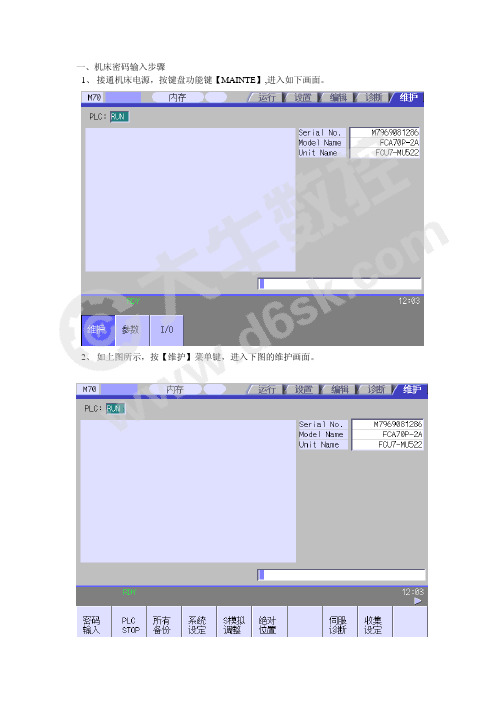
一、机床密码输入步骤1、接通机床电源,按键盘功能键【MAINTE】,进入如下画面。
2、如上图所示,按【维护】菜单键,进入下图的维护画面。
3、按【密码输入】软件,则提示要输入密码,此时在光标处输入“MPARA”并按键盘上【INPUT】键后,即完成了密码输入。
二、参数的搜索与修改1、按键盘功能键【MAINTE】,进入如下画面。
2、如上图所示,按【参数】软件,进入下图所示的参数设置画面3、接上图,选择【参数编号】软件,搜索要修改的参数,并按键盘上的【INPUT】键。
参照下图(以参数8001号为例)4、将要变动的数值输入到光标所示处,并按【INPUT】键后,即完成对该参数的修改。
三、加工程序的缓存区修改步骤功能简介:自动运转(内存、存储卡)运行时,可以停止程序段,对下一指令进行修正和变更。
另外在不发生错误时,可以不进行NC复位,直接对发生错误的程序段进行修改,然后继续运转。
1、按操作面板上的单节执行键,使程序处于单节执行状态。
按键盘上的【MONITOR】键,并通过菜单扩展键找到如下图所示的画面。
2、如上图所示,按【PRG修改】软件,进入缓存区修正界面,如下图:3、将光标移动到要修改的程序段,执行相应的修正,修改完成后按【INPUT】键即可。
4、确认程序修改无误后,则可以继续执行以下程序。
功能简介:利用程序搜索功能可以调用内存、串行设备和存储卡中的加工程序。
1、在运转画面中按【搜索】软件,进入如下搜索画面2、如上所示,选择要执行搜索的装置(存储器、串口或存储卡)。
下面以存储器搜索为例,按存储器软件,出现存储器内的程序,将光标移动要执行的文件名上,按【INPUT】键,即完成对该程序的搜索。
功能简介:程序再搜索功能是因刀具破损等原因暂时中断加工程序时,搜索到希望继续执行的加工程序段,从该程序段开始继续加工的功能。
1、在运转画面(按【MONITOR】后出现的画面),通过菜单翻页键找到如下所示画面。
2、如上图所示按【在搜索软件】,执行在搜索功能,如下图3、通过文件设定找到需要执行在搜索功能的程序,按键盘上的【INPUT】键后,即找到了上次结束前的程序段。
ZWGP系列无线电子手轮说明书

ZWGP系列无线电子手轮说明书使用本产品之前,请阅读本手册并妥善保存手册作日后参考适用于德国西门子(SIEMENS )、日本三菱(MITSUBISHI )、法那科(FANUC )、西班牙发格(FAGOR )、法国NUM 、台湾宝元、台湾新代等数控。
1、采用无线通讯频段,无线433MHZ 距离40米;2、采用自动跳频功能,同时使用32套无线手轮,互不影响;5、轴选和倍率信号支持二进制编码和格雷码等信号类型;4、支持6档轴选功能,3档倍率选择功能;6、支持5V 差分脉冲信号,非差分脉冲信号,24V 脉冲信号等多种脉冲信号类型;3、支持急停按钮功能,和3个扩展按钮开关量输出;7、低功耗设计,2节AA 电池可以使用1个月以上;注释:1、状态指示灯:电源灯(左一):OFF 档打开后,电源灯常亮; 信号灯(左二):操作手轮时,信号灯常亮;低电压报警灯(右一):电池电量过低时,报警灯闪烁或者常亮;2、使能按钮:按住使能按钮后,激活轴选和倍率信号,并且脉冲编码器输出有效;3、自定义按钮:无任何功能的按钮,控制接收器上对应的一个开关量输出;型号:ZTWGP-3:ZTWGP 接收器注释:1、状态指示灯:电源灯(左一):OFF 档打开后,电源灯常亮; 信号灯(左二):操作手轮时,信号灯常亮;低电压报警灯(右一):电池电量过低时,报警灯闪烁或者常亮;2、使能按键:按住使能按钮后,激活轴选和倍率信号,并且脉冲编码器输出有效;型号:ZTWGP:ZTWGP 接收器接收器功能介绍COM1:轴选倍率信号输出的公共端;可以接0-24V 公共信号COM2:3个自定义按钮输出的公共端;型号:ZTWGP 接收器:接收器端子定义产品功能描述注释:1、状态指示灯:电源灯(左一):OFF 档打开后,电源灯常亮; 信号灯(左二):操作手轮时,信号灯常亮;低电压报警灯(右一):电池电量过低时,报警灯闪烁或者常亮;2、正负快速移动按钮:按住“+”按钮,手轮连续发送正向脉冲; 按住“-”按钮,手轮连续发送负向脉冲;型号:ZWGP:ZWGP 接收器线号+5V 0V ABA-B-XYZ451X 10X 100X COM 红黑黄白透明白蓝黑棕黑红透明+黑蓝橙色绿黑白黑绿黑黄功能电源正极脉冲A相脉冲B相轴选X轴轴选Y轴轴选Z轴轴选4轴轴选5轴倍率1X档倍率10X档倍率100X档轴选倍率的公共信号颜色电源负极脉冲A-相脉冲B-相接收器功能介绍与端子定义无线电子手轮WGP型号规则059:产品外观:Z表示Z系列外观;9:TWGP:带急停按钮;WGP:则不带急停按钮:脉冲输出参数:01:表示5V,25毫安;A,B脉冲信号输出:100PPR03:表示5V,差分信号;A,A-;B,B-;脉冲信号输出:100PPR02:表示12V,5毫安;A,B脉冲信号输出:25PPR(适合三菱系统)04:开路输出;A,B脉冲信号.低电平,NPN输出.(适合PLC等)05:源极输出;A,B脉冲信号,高电平输出,PNP输出.(适合PLC):手轮支持的轴数量;5表示支持5轴;6表示支持6轴;:手轮轴选输出方式:A表示点对点输出;B表示编码输出:手轮倍率输出方式:A表示点对点输出;B表示编码输出:手轮支持的扩展按钮数量:3表示支持3个扩展按钮输出;:表示倍率特殊输出模式:X表示倍率信号为脉冲式输出(西门子系统专用):表示无线信号接收器的工作电压:05表示5V供电;12表示12V供电;24表示24V供电倍率编码输出1X和COM连通倍率10X: 10X和COM连通倍率100X: 倍率1X,10X都和COM连通倍率1X:型号:Z TWGP01-6 B A- 3 X脉冲输出选型指南型号参数描述适合系统电源DC5V,输出脉冲100PPR,相位输出为A,B两路脉冲序列A和B相差90;开路集电极电路,内装200欧5V上拉电阻日本法那科FANUC系统台湾中达电通TNC台湾忆图(HUST)系列国内如航天数控,华中数控,广州诺信凯恩帝KND等系列电源DC12V,输出脉冲25PPR,相位输出为A,B,两路脉冲序列A和B相差90开路集电极电路,内装2K欧12V的上拉电阻日本三菱MELDAS电子手轮(MELDAS M64;M65;E60等系统为电源DC12V,输出为DC5V)Gp01Gp02Gp03电源DC5V,输出脉冲100PPR,相位输出为A,A-,B,B-,采用5V差分脉冲信号输出适合台湾宝元,台湾新代SYNTEC系统,德国PA系统,典型如:海徳盟Higerman,海那克Higerman,广州数控GSK,开通数控 等数控系统;国外系统:西门子,NUM,西班牙法格FAGOR(NEW,8055I)等输出脉冲100PPR,相位输出为A,B两路脉冲序列A和B相差90;低电平,NPN输出日本法那科FANUC系统德国西门子等系列;适合PLC;Gp04输出脉冲100PPR,相位输出为A,B两路脉冲序列A和B相差90;高电平,PNP输出日本法那科FANUC系统德国西门子等系列;适合PLC;Gp05成都芯合成科技有限公司Chengdu XinHeCheng Technology Co .,Ltd网站:http ://www .wixhc .com客服电话:028-******** 如有印刷或翻译错误,望用户谅解。
Raveon M7系列无线电设备修改调制平衡指南说明书

Adjusting Modulation BalanceBy John Sonnenberg Raveon Technologies Corp OverviewThe M7 series of radio’s from Raveon use a transmit modulation technique called “dual-port modulation”. The transmitted signal is applied to both the VCO and to the VCTCXO in the radio’s RF synthesizer. The modulation of these two circuits must be exactly the same. When Transmitting two-level data, the balance between VCO modulation and TCXO modulation is much less critical.When transmitting 4-level modulation, the balance between VCO and TCXOmodulation must be precise. When sending 4-level data, it is highly recommended that the radio’s modulation balance be adjusted on the desired operating frequency, before the radio is installed.Modulation balance tends to change across the radio’s frequency band, so it is best to adjust it on the actual operating frequency. Raveon’s design has built-incompensation for the balance of the modulation, to keep it relatively consistent across the band. 2-Level verses 4-Level data“2-level” data, refers to a signal that digital 1s and 0s are represented by one of two different levels. On an FM radio, such as the Raveon’s M7 series, 2-level data is sent as either a positive deviation from center, or a negative deviation.2-Level ModulationTechnical BriefAN142 Rev A0For high-speed data, the digital data is encoded into 4 levels, and sent over-the-air as one of 4 frequency deviations. The 4 different levels correspond to the 4 binary combinations of two bits (00, 01, 11, and 10).4-Level ModulationIt is obvious looking at the two pictures, that the difference between signals on a 2-level signal is much greater that the distance between levels with a 4-level signal. This is why 2-leve radio system have much better communication range than 4-level systems, although their data rate is ½.Modulation BalanceBecause of the dual-port modulation method used in the M7, there is an adjustment in the M7 that effects the fidelity of the modulation. This is called the Mod Balance setting, and it is stored in register R9 of the radio.If Mod Balance is too low, the rise-time of the leading edge of the signals is too slow. If Mod Balance is too high, then the waveform will overshoot. Both phenomena will degrade the performance of the radio.Modulation balance is set at the factory, and normally should not be adjusted in the field.Only in the case where the radio is changed from two-level to 4-level modulation, or if it is a 4-level radio is changed in operating frequency, should the balance be adjusted. Mod Balance must only be adjusted by trained technicians with appropriate RFcommunication test equipment.Proper BalanceThe following screen captures illustrate properly balance 2 and 4-level waveforms. Well-balance 2-level signal Well-balance 4-level signalThese waveforms are created by causing the M7 to transmit a test pattern into an RF service monitor, and then viewing the recovered FM signal on an oscilloscope.To properly view this, it is vital that the FM service monitor, FM demodulator, and oscilloscope be DC coupled.Improper BalanceThe following screen captures illustrate what an improperly balance M7 will look like when viewing the recovered FM signal.Over-balance 4-level signal Under-balance 4-level signalOver-balance 2-level signal Under-balance 2-level signalTest EquipmentAn Agilent HP8910 or HP8921 is the ideal service monitor for testing FM deviation, and looking at the Modulation Balance. The M7 modulation is FM, so a high-quality FM modulation analyzer, FM deviation meter, or FM service monitor is required. Whatever FM deviation monitor is used, it must meet as a minimum these specifications:RF Frequency: 500MHzAudio Frequency: DC to 10KHzDe-emphasis: NoneResidual FM/noise: <50HzAn instrument with AC coupled audio cannot be used to adjust Modulation Balance. Only DC coupled instruments. It is easy to test if it is DC coupled. Simply change the frequency of the M7 by 1000Hz, and the audio output of the FM modulation analyzer should shift in DC voltage.Connect the audio-output of the FM modulation analyzer to an oscilloscope, preferably an old phosphor type, or a DSO will persistence. The oscilloscope must he DC coupled also.Setting the BalanceThis procedure is only to be used when adjusting the modulation for optimal performance on one specific frequency. After doing this procedure, the factory Modulation Balance settings are modified, and the radio should only be used on the one frequency it was compensated for.Setting the balance is done in the “Configuration” mode. See the user manual on how to enter the configuration mode. (+++ from a terminal)The balance setting is stored in register R9. Always record its setting before you begin balancing, so that you can revert back to the original setting if needed. Raveon calibrates the M7’s balance in the middle of the frequency band, using the R9 register. For the RV-M7-UC, the middle of the band is 460MHz.There are three test-patterns available to the technician to generate signals that are easy to see on an oscilloscope. The three test signals are generated with the following commands:ATTD 1(send random data)ATTD 3(send 10101.. pattern at ¼ the baud rate)ATTD 8(send 10101... pattern at the baud rate)You may want to turn the RF power down before adjusting the Modulation Balance. RF power may be set to 5 (ATPO 5), to reduce heat during this procedure. Remember after adjusting modulation, set the ATPO back to the setting as it was before turning it down.Begin by transmitting the ATTD 3 pattern, and adjusting ATR9 for best balance. Once a properly balanced 2-level signal is achieved, verify it by sending random data with the ATDT 1 command.For M7 radios that use 4-level modulation, verify that the “eye opening” is wide open. The ATR9 setting will adjust this, and while sending random data, adjust ATR9 for best eye opening.The oscilloscope must be adjusted to trigger at the 50% point in the wavefom to get a good view of the eye opening.Raveon Technologies Corporation2780 La Mirada Drive, CVista, CA 92081********************760-727-8004。
数控编程实验指导说明书(修改)
实验四数控车削仿真加工 实验五数控车削仿真加工 实验六数控车削仿真加工 (插补指令)(一) (简单固定循环加工) (螺纹加工)(三) 11 实验七数控车削仿真加工 实验八数控车削仿真加工(外园粗车循环加工)(四)••…(固定形状粗车循环加工)(五)13 15实验九 XK6325B 数控铣床KND-100M 数控系统面板及其操作 17实验十数控铣床对刀操作及工作坐标系 数控铣床刀具补偿功能的使用2022实验^一数控铣削仿真加工(插补指令)—用G01、G02/G03编写一个简单零件的外形铣削加工程序(一层一次) 实验十二数控铣削仿真加工(插补指令)—用G01、G02/G03编写一个简单零件的外形铣削加工程序(二层一次) 实验十三数控铣削仿真加工(插补指令)2729—用G01、G02/G03编写一个简单零件的外形铣削加工程序(二层二次) 实验十四 数控铣削仿真加工(钻孔循环指令)(四) 30实验十五数控铣削仿真加工(子程序调用)(五)实验一 、实验目的数控车床GSK980■数控系统面板及其操作实验一数控车床GSK980T 数控系统面板及其操作 实验二对刀操作及数控车床工作坐标系实验三数控车床刀具补偿功能的使用(1)熟悉GSK980T面板的结构和组成。
(2)掌握数控系统的六种工作方式。
(3)掌握数控系统显示状态的切换。
(4)掌握MDI运行模式。
二、实验设备及实验系统(1 )数控车床二台。
(2 )电脑一人一台。
(3)GSK980T仿真系统。
三、实验内容及步骤1、观察GSK980T数控面板的三大组成部分:LCD显示器、MDI键盘、控制面板。
2、通过切换“位置、“程序”“刀补”“报警”“设置”“参数” “诊断”观察LCD 显示内容的变化。
3、通过“手动”“手轮”“回零”“录入”“编辑”“自动”六种工作方式的切换,了解数控系统的六种工作模式。
(1)手动模式:在该模式下做如下动作:移动刀具(X、Z方向);主轴正反转、停止;冷却液开/关;手动换刀。
智能手轮使用说明书1
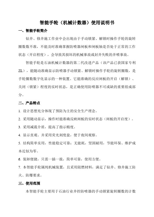
智能手轮(机械计数器)使用说明书一、智能手轮简介钻井、修井施工作业中会出现由于手动锁紧、解锁时操作手轮的旋转圈数数不准,不能及时准确掌握防喷器闸板和闸板轴是否处于正常的工作状态(开启程度),会导致其损坏的机械事故或封井失败的井喷事故。
智能手轮是石油机械计数器的第二代改进产品(该产品已获国家专利ZL),能随动准确显示防喷器手动锁紧、解锁时操作手轮的旋转圈数,是手轮圈数数字化显示的一种装置。
它能准确的反应闸板的开启(解锁)、关闭(锁紧)程度的实时状态,是正确使用防喷器不可或缺的重要组成部分。
二、产品特点1. 设计思想充分体现了预防为主的安全生产理念。
2. 采用随动显示,操作时能准确反映闸板的实时状态(闸板的开启度)。
3. 采用减震介质,提高了指示精度。
4. 显示直观、并采用荧光刻度盘,便于夜间观察。
5. 结构简单实用,性能稳定可靠;无能耗,坚固耐用,节能环保、维护成本近似为零。
6. 装卸便捷,只需一插一拔,简单可靠,使用方便。
7. 本智能手轮属纯机械装置,且采用阻燃材料,满足了钻井、修井施工防火、防爆要求。
三、使用范围本智能手轮主要用于石油行业井控防喷器的手动锁紧旋转圈数的计数装置,也可用于其他行业的手轮旋转圈数计数。
四、技术规范及型号1.型号:JZ 04 2 W2.量程:内圈36圈,外圈1(360)圈;3.引用误差:0.5%4.工作温度:-50℃~+100℃五、使用方法1. 卸下锁紧杆手轮螺母及垫片;2.将智能手轮的垫圈插座套在锁紧杆上并装上垫片,再拧锁紧杆手轮螺母;3.确认闸板开启到位,锁紧杆解锁到位;4.调零:使表盘近似处于铅垂面内,转动表壳使长、短表针重合并指向刻度盘“0”点;5.转动表壳,保持表针指“0”的状态,在此状态下将弹性插头插入垫圈插座中,智能手轮安装完成处于待命工况;6.旋转手轮时,即可随动显示手轮旋转的圈数。
六、维护保养1.每班清洁保养;2.每天早、晚对巡检一次;3.每班巡检表内的减震液的液面;4.减震液的液面高度:上限表直径的4/5,下限表直径的2/3;5.减震液的液面高度低于下限值需通过注液孔加注AF201二甲基硅油至上限位置;6.搬家时卸下表头放回仪表箱,严禁重压、碰撞、坠落等造成的损坏。
WHB04 MACH3雕刻机无线电子手轮说明书

Update Driver for MPG wireless Mach 3What do you mean by reinstall? I just have the ShuttlePro.dll that I copy to Mach3/Plugins.It is the last one that you sent me here modified: 1/13/2012If you work(zero) in a pocket/hole then you need to set the SAFE-Z so that the z-axis retracts before the others so that it does not crash.(see pic)When it is enabled then any movement of the y-axis causes the z-axis to home.When setting up for an undercut etc. it damages the tool and pulls the job out of the clamps as it goes up suddenly.I have not tried the x-axis.:MACH3 PROBLEMIt still runs away every now and again -also when the pendant is switched on after Mach3 is started, or change from STEP to CONT in Mach3 with the mouse and changes are made to MOTOR TUNING. It also still stops the config menus from opening.There are probably more problems but I try not to use it as it has cost me too many carbide cutters and material alreadyIt is unsafe as there are just too many unexpected behaviours, I am just lucky that I have not damaged a machine yet.Answer: xhc wireless tec Chengdu chinawhen enable safe high and”goto safez when stop button is hit”, our pendant will auto send stop button during reverse moving and switching band.so we advice you disable”goto safez when stop button is hit”.。
FANUC系统手轮的应用归纳
FANUC 系统手轮的应用归纳
发博人生 杜江华
一 使用手轮的参数设置 ※FS-0 900#3=1,第一手轮生效 902#0=1,第 2/3 手轮控制生效
※FS16i/FS18i 9920#3=1,手轮控制生效 9922#0=1,第 2/3 手轮控制生效
二 手轮方式选择 ※FS-0
FOXBLE
-1-
※FS16i/FS18i
通过上表对应,也就是说手轮方式选中为 G43.2=1。
在 PLC 中进行条件给定置为 1。
三 手轮进给轴选择信号 ※FS16i/FS18i
第一手轮的选择信号对应轴如下表:
四 手摇轮进给率选择信号 系 统 T 系列 MP1 G117.0 MP2 G118.0 MP1 G120.0 G19.4 M 系列 MP2 G120.1 G19.5
系
列
0 系统 FS16i/18i 系列 ※FS-0 ⑴对应倍率选择如下:
FOXBLE
-2-
⑵需要设置的参数
※FS16i/FS18i 系列 ⑴对应倍率选择如下:
⑵需要设置的参数
五 信号和硬件 信号
FOXBLE
-3-
硬件
参考文献 1. FANUC 0i-A 连接说明书硬件,BEIJING-FANUC 2. FANUC 0/00/0-Mate系统维修说明书,BEIJING-FANUC LTD, 1999 3. CNC维修教材FS16i18i21i发那科学校讲义,BEIJING-FANUC,B-10143/09 FOXBLE -4-
。
980MC2980TC2手轮接口补充说明
980MC2/980TC2手轮接口补充说明
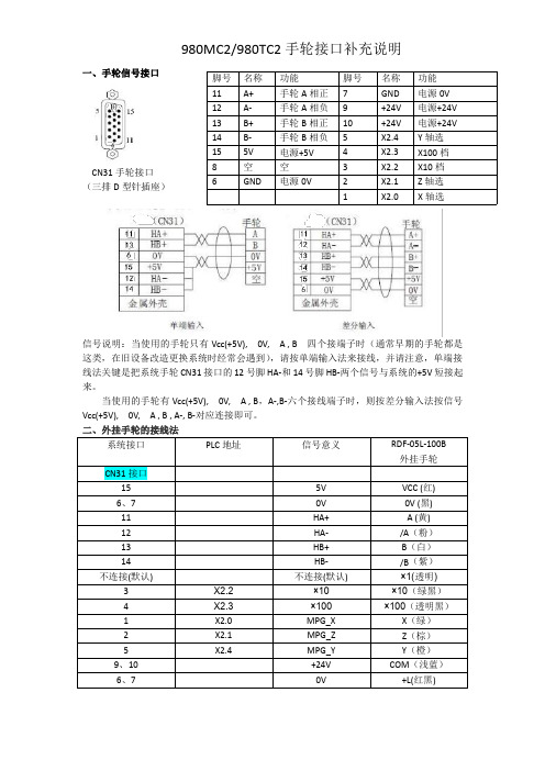
一、手轮信号接口
CN31手轮接口(三排D
型针插座)
信号说明:当使用的手轮只有Vcc(+5V),0V,A ,B 四个接端子时(通常早期的手轮都是这类,在旧设备改造更换系统时经常会遇到),请按单端输入法来接线,并请注意,单端接线法关键是把系统手轮CN31接口的12号脚HA-和14号脚HB-两个信号与系统的+5V 短接起来。
当使用的手轮有Vcc(+5V),0V,A ,B ,A-,B-六个接线端子时,则按差分输入法按信号Vcc(+5V),0V,A ,B ,A-,B-对应连接即可。
二、外挂手轮的接线法
系统接口PLC 地址
信号意义
RDF-05L-100B 外挂手轮
CN31接口
155V VCC (红)6、70V 0V (黑)11HA+A (黄)12HA-/A (粉)13HB+B (白)14HB-/B (紫)不连接(默认)
不连接(默认)
×1(透明)3X2.2×10×10(绿黑)4X2.3×100×100(透明黑)
1X2.0MPG_X X (绿)2X2.1MPG_Z Z (棕)5X2.4
MPG_Y Y (橙)9、10+24V COM (浅蓝)6、7
0V
+L(红黑)
脚号名称功能脚号名称功能11A+手轮A 相正7GND 电源0V 12A-手轮A 相负9+24V 电源+24V 13B+手轮B 相正10+24V 电源+24V 14B-手轮B 相负5X2.4Y 轴选15
5V 电源+5V 4X2.3X100档8空空3X2.2X10档6
GND
电源0V
2X2.1Z 轴选1
X2.0
X 轴选。
PlanetCNC 无线手轮用户手册说明书

PlanetCNC Wireless handwheel user manualSupported features:-Wireless communication-No additional software plug-ins needed-Display with backlight showing work, machine coordinates and override -All 9 axes supported-5 selectable jogging modes-Spindle override control-Feed override control-Machine control buttons (E-Stop, Start, Pause…)-Button function customization-Offset control buttons-Spindle and coolant control buttons-Durable rubber protection guard-Long lasting batteries (Batteries are not included!)-High quality long range easy mountable antenna with detachable cableKit includes:-Wireless handwheel with rubber guard-Antenna with extension cable-USB dongle transceiver-Metal hanger bracket and screws for mounting-Requires 2 x AA batteries (Batteries are not included!)Startup process:-Insert 2 x AA batteries-Attach cable with antenna and USB dongle.-Connect the USB dongle with your PC's USB port.-Turn ON the handwheel using ON/OFF switch-Launch PlanetCNC TNG sw and check the Jogging/Handwheel settings section.If handwheel is recognized by TNG software, Wireless Handwheel option should be enabled:Handwheel button layout:Handwheel button functionality:E-Stop button:Initiates E-Stop.Start:Starts program.Pause:Pauses program.Stop:Stops program.+Offset zero button:Sets work position offset value to zero.Work position XY zero button:Sets current XY work position to zero.Work position Z zero button:Sets current Z work position to zero.Flood ON/OFF button:Turns flood ON/OFF.Mist ON/OFF button:Turns mist ON/OFF.+Measure Height button:Initiates Measure Height procedure.Measure Tool Length button:Initiates Tool Length measurement procedure.Move To Zero XY button:Initiates Move to Zero procedure.Home button:Initiates Home procedure.+Spindle ON/OFF button:Turns spindle ON/OFF.Cycle button with axis knob selected:Toggles Machine and Work coordinates.Selects group of axes: X,Y,Z or A,B,C or U,V,W+Cycle button with feed override know selected: Toggles Feed and Traverse override.Axis, Feed override, Spindle override and Info select switch:X,Y,Z (A,B,C,U,V,W): Axis selected will move when encoder wheel is rotated.F: Feed speed and traverse override menu.S: Spindle speed override menu.C: Additional info of currently selected jogging mode or macro selection (see button customization chapter)Jogging mode select switch:Selects jogging mode from 1-5. Jogging modes are configured in PlanetCNC TNG sw under File/Settings/Jogging/Handwheel. See PlanetCNC TNG user maual for more info.Button function customization:User can customize handwheel button functionality. This can be done by configuring the Handwheel.txt file.First, create a blank Handwheel.txt file and place it in your profile root folder.How to configure this file will be described further in this document.Button HEX values:Each button of the handwheel keypad is represented by its default HEX value. These values could also be in a decimal form, but HEX gives better and more intuitive description.Each button can be represented with two types of HEX values, Lower HEX (SHIFT button is not active) and Upper HEX values (SHIFT button is active).Best to describe it is by using illustrated view:Lower HEX button values (SHIFT button not active):While holding SHIFT button, each buttons is now represented with the Upper HEX value:Now that we know LOWER and UPPER values of each button, we can easily assign new alternative functions of the handwheel buttons.BASIC Handwheel.txt file configuration:Earlier chapter can be better described with the actual command lines of the configuration file.Below are a default* program functions that will be executed when corresponding button will be activated:cmd: "Machine.Emergency_Stop" "" num=0x0001cmd: "Machine.Start" "" num=0x0002cmd: "Machine.Pause" "" num=0x0003cmd: "Machine.Work_Position.Offset.To_Zero" "" num=0x0004cmd: "Machine.Work_Position.Axis_To_Zero.XY" "" num=0x0005cmd: "Machine.Work_Position.Axis_To_Zero.Z" "" num=0x0006cmd: "Machine.Flood" "" num=0x0007cmd: "Machine.Work_Position.Measure_Height" "" num=0x0008cmd: "Machine.Tool_Offset.Measure_Length" "" num=0x0009cmd: "Machine.Move.Axis_To_Zero.XY" "" num=0x000acmd: "Machine.Spindle" "" num=0x000b*(Note that this is a default behaviour of handwheel buttons. No configuration file or configuration of it is needed to obtain it… )Lines below will execute Homing procedure, Machine Stop and Mist ON/OFF actions. Becuse upper HEX values are used, this indicates that SHIFT button needs to be pressed: Homing procedure:cmd: "Machine.Home" "" num=0x0a00+Machine Stop:cmd: "Machine.Stop" "" num=0x0300+Mist On/Off:cmd: "Machine.Mist" "" num=0x0700+So if user wishes to add an alternative functionality to a button, all it needs to be done is to add a line which would execute desired program function. Upper HEX value of button should be used.Example:We would like to execute Surface Measure procedure when we press the Start button in combination with SHIFT button.Since we will assign an alternative button functionality we need to obtain the Upper HEX button value. Earlier chapter with the layout illustration gives this information → 0x0200 Cmd line is usually the menu path of the program function. In this case this would be: Machine/Measure/SurfaceNote that path menu levels are represented with “.” and spaces in the program function name with “_” character.Command line that would help us achieve this is:cmd: "Machine.Measure.Surface" "" num=0x0200If we would like to turn ON/OFF Output 1 with the same button instead, we would write: cmd: “Machine.Outputs.Output_1” "" num=0x0200ADVANCED Handwheel.txt file configuration:Since there are not enough buttons for every possible function of tool that TNG offers, macros can be created. Macros are able to execute program functions, expression functions, parameter manipulation etc.They can be navigated and used trough the Custom menu.How to create a macro:Just as we added command lines for button alternative functions to Handwheel.txt file, in the same way we add dedicated lines to create macros.We will demonstrate three examples of macro use. Macro for program function, program function with parameter manipulation and expression function.Macro command line for program function File Open:cmd: "File.Open_..." "Open file" num=0x10001cmd: "File.Open_..."Like before, command line is the path of the program function, File/Open"Open file"Macro will be displayed under this name in the custom menu.num=0x10001This num value serves as a macro ID as also as a menu sequence number.First value 1 identifies this as a macro line, and last value 1 is its sequence number.Macro command line for expression function with parameter manipulation:cmd: "Machine.Output_PWM" "PWM" num=0x10002 param=0|10|0|100 val="[0;expr:_hw_mpg_custom]" cmd: "Machine.Output_PWM"Like before, command line is the path of the program function, Machine/Output_PWM "PWM"Macro bill be displayed under this name in the custom menu.num=0x10002This num value serves as a macro ID as also as a menu sequence number.First value 1 identifies this as a macro line, and last value 2 is its sequence number. param=0|10|0|100These are definition values of PWM signal that will be changed trough this macro. So, when the PWM signal will be modified, if will consider these definitions:0[initial value] | 10[increment value] | 0[min value] | 100[max value]val="[0;expr:_hw_mpg_custom]"0 is a number of output pin that will generate the PWM signal. Zero based numbering is used (1st pin has number zero, 2nd pin has number one etc…)Macro uses parameter _hw_mpg_custom for PWM signal value modification.Macro command line for expression function:This macro executes expression function located in the Expr.txt file.expr: "exec('#Message')" "Message" num=0x10003expr: "exec('#Message')"Since exec is an expression function, we need to use expr command at the beginning of the macro line. exec command will execute the #Message function located in our Expr.txt file.In this case, #Message function looks like this:#Messageexec(msg('Handwheel function trigger'));“Message"Macro bill be displayed under this name in the custom menu.num=0x10003This num value serves as a macro ID as also as a menu sequence number.First value 1 identifies this as a macro line, and last value 3 is a sequence number.Accessing and using the Custom menuCustom menu can be accessed using axis switch knob set at C position:At first, display will show current jogging mode info. If the handwheel encoder is rotated custom menu will be displayed.As per our configuration, three macros will be available for selection. Using a handwheel encoder, user can navigate trough the menu items:To execute the Open File or Message macro, macro should be selected in the menu and confirmed with Cycle button:To execute PWM macro, we select it in the menu and by simultaneously using a Shift button and an encoder wheel we can change the PWM duty cycle value:To actually set PWM on the output pin, we just need to confirm it with the Cycle button:。
FANUC数控系统操作手册
1版权声明佳泰数控(泉州)有限公司保留所有权力本操作手册由佳泰数控(泉州)有限公司编制,公司有权力不通知用客的情况下,修改本手册。
佳泰数控不承由于不正确使用本手册和机床的情况下,所造成的一切间接,直接或附带的损失和人员伤害。
在未经许可的情况下,不得擅自修改,复制,出售本手册,由此造成的法律纠纷,本公司概不负责。
前言感谢您使用我公司的数控机床我们以领先世界的数控技术,可靠性能,完善的售后服务,高效的技术支持,为你的发展尽一臂之力。
关于我们更多的信息佳泰数控(泉州)有限公司网址:想了解更多关于我们公司或者产品信息可以登陆。
您可以通过电话或者信件的方式,和我们的技术人员进行沟通。
你可以通过以下的途径获得我们的技术支持和售后服务电话:电子邮箱:传真:通信地址:本手册的目的:·了解熟练地使用我公司的数控机床·能对机床进行日常维护和保养·能正确地使用我公司数控机床的各项功能本手册的使用对象:·数控机床操作人员·数控编程工程师·数控机床的维护和保养人员本手册的主要内容11.操作面板说明1.1 操作面板的外观1.2 操作面板功能说明 紧急停止1.21 按下该按钮可以使机床各马达处于停止状及外部电源,机床处开启状态。
1.22 机床处于以下状态中:(A ) 所有轴(包括第四轴)停止移动。
(B ) 主轴停止转动。
(C ) 显示屏显示异警信息。
(D ) 异警红灯亮。
(E )刀库的旋转及换刀的动作停止。
1.23解除方法:将此按钮顺时针方向旋转,即可。
但是有下列几点必须要考虑: (A ) 只有在解除了紧急停止的问题来源后,才可以复归这个按钮。
(B )紧急停止的命令和状态解除后,机床必须再重新执行。
当在更换刀具的过程中,按下紧急停止按钮后所有的动作都会停止,所以可能刀库会未定位,必须让它回到正确位置。
操作模式1.24 操作前请确定好操作模式。
1.25 共有七种模式可供选择 (A )增量有四档: ×1、×10、×100、×1000。
弘欣自动四轴伺服机械手使用说明书 V2.00

5.1.10. 堆叠设置说明................................................................................................30 5.1.11. 系统设置说明................................................................................................32 5.1.12. 文件管理说明................................................................................................33 5.1.13. 维护说明........................................................................................................34 6. 7. IO 实时状态说明................................................................................................. 35 告警列表说明.......................................................................................................37
四轴伺服机械手控制系统 使用说明书
第 1 页 共 63 页
四轴伺服机械手控制系统使用名书 版本号:2.00
深圳市弘欣自动化科技有限公司
前 言
本系统在出厂前已经过严格检查。 五六轴伺服机械手控制系统购入后, 请检查本系统是否因运输不慎而造成 损伤;产品的规格、型号是否与订购产品的机种相符;有无合格标志等。如有 问题,请与本公司或供应商联系。 本系统安装须注意以下几个事项: ● 外部电源发生异常,控制系统会发生故障,为了整个系统安全工作, 请务必在控制系统外部设置安全电路。 ● 安装、配线、运行、维护前,必须熟悉本说明书内容;使用时也必须 熟悉相关的机械、电子常识及一切有关安全的注意事项。 ● 请安装与金属等阻燃物上并远离可燃物。 ● 配线作业必须由专业电工进行。 ● 确认电源断开后才能开始作业。 ● 使用环境温度为 0~50℃,不要使用在结露及冰冻的地方
KND凯恩帝数控系统说明书
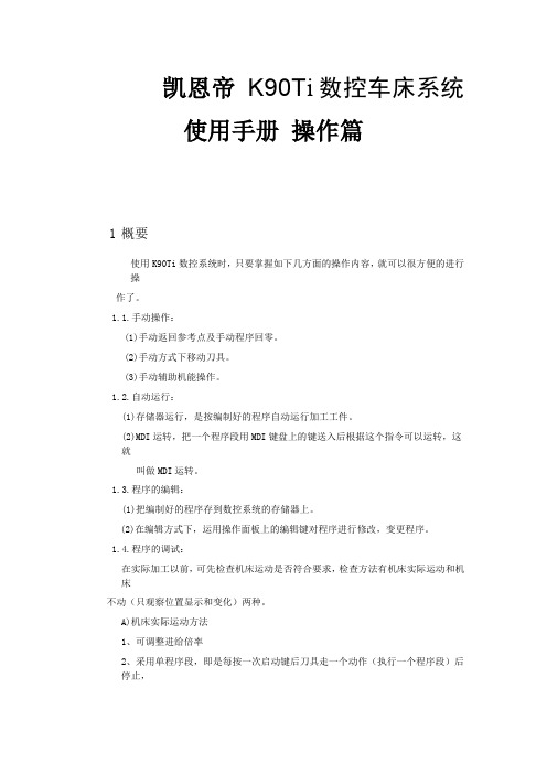
凯恩帝K90T i数控车床系统使用手册操作篇1概要使用K90Ti数控系统时,只要掌握如下几方面的操作内容,就可以很方便的进行操作了。
1.1.手动操作:(1)手动返回参考点及手动程序回零。
(2)手动方式下移动刀具。
(3)手动辅助机能操作。
1.2.自动运行:(1)存储器运行,是按编制好的程序自动运行加工工件。
(2)MDI运转,把一个程序段用MDI键盘上的键送入后根据这个指令可以运转,这就叫做MDI运转。
1.3.程序的编辑:(1)把编制好的程序存到数控系统的存储器上。
(2)在编辑方式下,运用操作面板上的编辑键对程序进行修改,变更程序。
1.4.程序的调试:在实际加工以前,可先检查机床运动是否符合要求,检查方法有机床实际运动和机床不动(只观察位置显示和变化)两种。
A)机床实际运动方法1、可调整进给倍率2、采用单程序段,即是每按一次启动键后刀具走一个动作(执行一个程序段)后停止,再按启动键后刀具走下一个动作后(执行下一个程序段)停止,这样可以检查程序。
B)机床不动,观察显示位置变化或通过图形功能,观察加工时的刀具轨道的变化。
1.5.数据的显示和设定:(1)刀具补偿的显示和设定方法。
(2)参数的显示和设定。
(3)用诊断参数判断机床的输入输出口信号状态。
1.6.显示:(1)程序的显示。
(2)位置的显示。
(3)报警信息显示及处理。
1.7.电子盘的存取。
1.8.图形功能。
2操作面板说明2.1 面板区域划分K90Ti车床系统K90Ti的LCD/MDI面板见下图:2.1.1 LCD液晶屏显示区K90Ti数控系统采用7.4英寸单色液晶屏显示。
2.1.2 前置串口、U盘接口区为了使用户的使用方便,本系统前后均有串口接口,并增加U盘功能。
2.1.3 编辑键盘区2.1.4 显示界面菜单区2.1.5 机床面板区注:1.手动方式下轴旋转后,如果按任何主轴键(正转,反转,停止,点动),都会使主轴停止。
自动方式下:主轴旋转后,指定当前旋转的反向时,报警,暂停程序执行。
MACH3电子手轮说明书
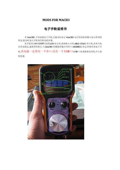
MODS FOR MACH3电子手轮说明书本MACH3专用高级电子手轮,它能实时显示MACH3运行的坐标参数与显示常用的状态.能实时显示手轮每次转动的步数.其手轮用240*320TFT高清LCD显示屏,系统核心才用ARM STM32单片机,其单片机具有高稳定,速度快等特点.与MACH3的数据传输才用串口MODBUS协议.即使用本电子手轮,其电脑一定要有一个串口.还有一个USB口,USB口是来做取电用的,不占系统资源.安装与调试:1:先将手轮的串口母口与电脑的串口公口连接,并固定好螺丝紧上,再把USB插头与电脑USB连接,并打开MACH3(V3.041).2:按(设置) (端口/针脚) 如下图中所示:先按上图所示设定,在编码器/电子手轮说明有详述.V1.84版本请重新启动MACH3.3:设置ModBus控制:超时时间在超时的时间设置说明有详述4:将脚本文件Macropump.m1s复制到C:\Mach3\macros\Mach3Mill文件夹里,如果MACH3装在其它盘,请拷在所在的文件夹下的\Mach3\macros\Mach3Mill文件夹里.5:总体设置:6: 重新启动MACH3,后按键盘上的TAB键呼出手轮图:这时转动手轮上的功能键,MACH3上的手轮图指示会相应改变.编码器/电子手轮说明:Counts/Unit是指手轮每转动N格才算一步,比如写上2,档位在0.1时,这时要转两格才进0.1. Velocity是全速时的速度,输入数字大,手摇控制的轴速度小,反之越大.超时的时间设置说明:当正确设置会显示No error提示,如出现Receive Timeout 提示,那很表示没有设置好参数或手轮没接好,请重新按每步来做.No error与Receive Timeout交替出现,则说明所设置的超时时间过小,适当改大,即可.参考值20-60之间.高级手轮使用:1 LCD屏显示说明:LCD屏分成4个区: 轴实时坐标MACH3返回状态区功能区功能键选取显示区轴实时坐标显示会与MACH3在电脑上显示同步,但精度只会0.001小于时会按四舍五入来显示2 功能键说明:共有二个功能键: MODE AXIS MPGMODE是选择每步的运行距离值, 有1 , 0.1 , 0.01 , 全速四档AXIS MPG 是选择要控制的那个轴与功能控制1 当选取电脑档位时控制权交给电脑,手轮当显示作用,正常下加工时打到这个档.2 当选取X,Y,Z,A 时就是控制对应的轴3 当选取功能档位功能区会显示出功能组,功能组相当于MACH3上的功能键,转动手轮当前红色光标会跟着改变,当指定到所要的功能时,按下手轮中间,1秒钟(有一定的延时,防止错按),当前的光标颜色变成绿色,即可.3 实时步值:这个功能是高级手轮一个特点,可以实时看每次走的步值当选取所要控制的轴后,会有一个实时步值出现实时步值是反应手轮每次转动的步值数, 按手轮中间的可以清零比如现在想控制X轴正走4mm 这时只要把MODE档位打到0.1 , AXIS打到X 再按一次手轮中键清零实时步值,慢慢正转手轮,当实时步值达到40后停止转动.这时机台会精确正加4mm4单相紧急复位键单相紧急复位是相当于MACH3紧急复位,但它是单相的(这个是特意这样安排的),所谓单相是指当按此键时,只能让MACH3停止工作,要复位只能按MACH3上的紧急复位,注意事项:当选取1mm时要注意了,因为手摇的速度是机台运行速度的几倍,所以会出现,当摇柄停下后,机台还在走的情况(可以调高MPG进给速率)!!!!!!新手一定注意了!建议新手先用0.01档或0.1档与全速档位!如果想让手摇时机台的速度加快,调MPG进给速度,方法是:用鼠标点MPG进给速率筐,这时MPG输入筐会显白,直接输入所要的速度,后按回车,(一定要记住按回车才能生效!!!).。
海德汉_HEIDENHAIN_iTNC_530_编程操作手册1012
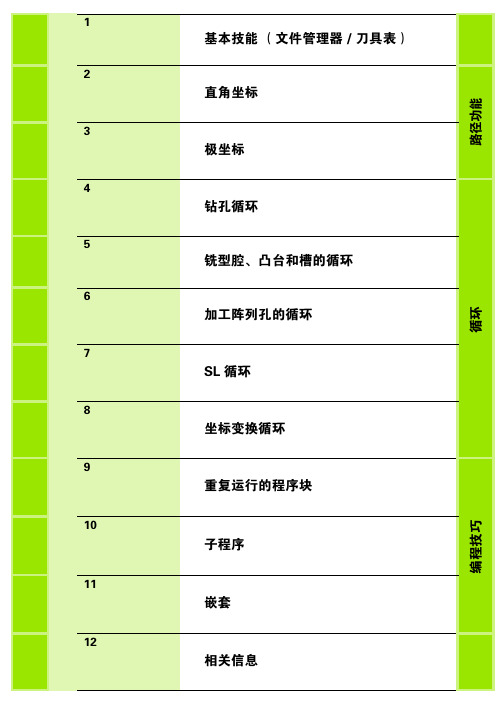
1基本技能(文件管理器/刀具表)2直角坐标路径功能3极坐标4钻孔循环循环5铣型腔、凸台和槽的循环6加工阵列孔的循环7SL 循环8坐标变换循环9重复运行的程序块编程技巧10子程序11嵌套12相关信息+Z+Z+Z基本轴旋转轴平行轴X A U Y B V ZCWX键盘TE 420TE 5301字母键盘用于输入文本和文件名,以及ISO 编程。
双处理器版本: 提供其他的按键用于Windows 操作。
2文件管理器、计算器、MOD 功能和HELP (帮助)功能3编程模式4机床操作模式5编程对话的初始化6方向键和GOTO 跳转命令7数字输入和轴选择8鼠标触摸板: 仅适用于双处理器版本124376518432765显示单元1软键区2软键选择键3软件行切换键4设置屏幕布局5加工和编程模式切换键6预留给机床制造商的软键选择键7预留给机床制造商的软键行切换键13423675123345屏幕布局编程模式显示机床操作模式显示机床操作模式(后台)编程操作模式、对话、出错信息(显示在前台)程序机床功能的软键软键区机床操作模式、对话、出错信息(显示在前台)编程模式(后台)程序或位置显示机床功能的软键机床状态软键区操作模式键操作模式功能程序编辑 编写及修改程序(RS-232-C/ V.24数据接口)试运行 静态测试 / 有图形模拟或无图形模拟几何尺寸是否相符数据是否缺失手动 移动机床轴显示坐标轴值设置原点手轮 用电子手轮移动设置原点手动数据输入定位(MDI) 输入定位步骤或输入可以立即执行的循环 将输入的程序段保存为程序程序运行-单程序段 分段运行程序,用Start(开始)按钮分别启动各段...开始程序运行-全自动 按START EXT(机床启动按钮)后连续运行程序文件管理驱动器1以太网RS-232接口 RS-422接口 TNC的硬盘当前路径或文件名3文件信息文件名:保存在当前目录下的文件及文件类型字节:以字节为单位的文件大小状态:M:“程序运行”模式下所选择的文件。
远程终端和电子手轮说明书

Remote terminals and electronic handwheelsNSMHC NSMHCDescription:• Lightweight and ergonomic• 5” TFT LCD touch screen (stylus, touch screen integrated)• Screen resolution: 480 x 272• Power supply / load: 24 V DC +/- 25%• Navigation keys and axis, feedrate and working mode selector switches • USB for fi rmware updates• Magnets for mounting on machineryOperation:• 2 potentiometers: FEED and SPEED• Manual mode control: jog / incremental / handwheel •3-position enabling switch (deadman switch):ON/ OFF / PANIC • E-stop button• Status LED: terminal and/or base load diagnostics• Axis movement in manual mode: JOG / electronic handwheel •R emote control of the machine: START / STOP / RESET.Zero preselection of the axes, block programming in MDI• Remote tool management: viewing and editing of tool tables, writing of technological data, measuring of tool length • Remote source management: visualization of the source/claw table, pre-selection and activation of source table • Confi guration of the terminal and diagnostics via the PLC and terminal • Simple and intuitive PLC user integrationDirect access to advanced CNC features while using an interface similar to that of the CNC 8065, through ISO instructions that may be directly programmed and executed via the remote terminal.HBH remote terminalsL O N G I T U D D E C A B L E E X T E N D I D OCONECTOR 23 PINESSOPORTE MAGNÉTICO700880 - 40005000XYZ 4110100567PULSADORL O N G I T U D D E C A B L E E X T E N D I D OCONECTOR 23 PINESSOPORTE MAGNÉTICO68700880 - 40005000E L E C T R O N I C H A N D W H E E L SUFO series100P / 100E seriesPortable (100P)Built-in (100E)Characteristics100 P100 EAxis selector push button yes noPulses / Turn 25Supply voltage Between 5 and 24 V DC Output signals Two A and B pulse trains shifted 90ºTurning speed 600 rpm Cable length Shielded 3 m cable with 7-pin connec1 m cable, fl at mounting faceplate and without connectorSealing IP 53 (DIN 40050)Weight1 KgOperating temperatureBetween 0 ºC and 60 ºCCharacteristicsPulses per turn 100Supply voltage 5 VOutput signals 5 V differential TTL 100 pulses / turn Turning speed 200 rpm (max. 600 rpm)Life Over 1 million turns at 200 rpmSealing IP 53 (DIN 40050)Weight 0.2 KgOperating temperatureBetween -10 ºC and 60 ºCworldwide automationATHENS BARCELONA BJERRING BRO BUCHAREST BUDAPESTCLERMONT FERRAND GOMEL GÖPPINGENGÖTEBORG ISTANBUL IZEGEM KAPELLEN KOTLIN LANGENTHAL LOG PRI BREZOVICI MILANO MOSKVA NEUCHATEL NORTHAMPTON PORTO PARDUBICE ROOSENDAAL THESSALONIKI TOIJALA TROYAN UTRECHTWIENER NEUDORF WUPPERTALUSURBIL ESKORIATZA BEIJINGMONDRAGÓNAUCKLAND DUNEDIN MELBOURNE SYDNEYBOGOTÁBUENOS AIRES CHICAGO DALLASEL SALVADOR D.F .LIMALOS ANGELES MEXICO D.F .MONTERREY N.L.MONTEVIDEO MONTREAL NEW JERSEY SANTIAGO SAO PAULO TAMPA TORONTOJOHANNESBURGBANGALORE BANGKOK CHENGDU DELHI GUANGZHOU HO CHI MINH CITY HONG KONG JAKARTAKUALA LUMPUR MANILA NANJING PUNE RAJKOT SHANGHAI SHARJAH SEOUL SINGAPORE TAICHUNG TEL-AVIV TOKYOE-mail:***********************s ub s id i a r y d i str i b u t oramericaafricaeuropeasiaoceaniaHeadquartersPlantsE P S - H A N D W H E E L S E N 0717。
elesa dd52r-e-rf 无线主轴定位装置 使用手册说明书
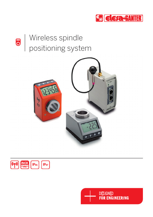
Wireless spindle positioning systemSTAINLESS STEELINO XIP 65IP 672Efficient Machine Set-UpThe system allows to save time during the format alignment process.• Once the set-up profile has been called up by PLC, UC-RF control unit transmits the target position to each DD52R-E-RF position indicator.• The current / target position is displayed on LCD display of DD52R-E-RF indicator.• The operator manually sets the position of the spindles following the arrow displayed on LCD display (clockwise/anti-clockwise rotation).• Once all the spindles are correctly set, UC-RF control unit communicates to PLC of the machine that the set-up has been completed.WIRELESS SPINDLE POSITIONING SYSTEMELESA and GANTER models all rights reserved in accordance with the law.Always mention the source when reproducing our drawings. The wireless system, consisting of UC-RF control unit and up to 36 electronic position indicators DD52R-E-RF, is designed for an efficient manual spindle positioning.DD52R-E-RF position indicators (Elesa Patent) are networked to UC-RF control unit via radio frequency (RF), so that connecting cables are not required for an easy and quick installation.Current and target positions are transmitted via RF, from and to the control unit, facilitating machine set-up.Easy installationUp to 36 position indicators can be networked (via radio frequency) to a single control unit.No cables required to connect the position indicators to the control unit.SafetyThe system can prevent the machine from starting up until the machine set-up is completed, avoiding production issues and risks for the operators.Up to 36indicators DD52R-E-RFFig.23WIRELESS SPINDLE POSITIONING SYSTEMELESA and GANTER models all rights reserved in accordance with the law.Always mention the source when reproducing our drawings.Flashing displayWhen the DD52R-E-RF indicator receives a new target position from the UC-RF, the display starts flashing as indication of a non-correct position. On the display appears the distance to the new target position; the display will stop flashing once theoperator reaches the zero, meaning the indicator has been correctly moved to the new target positionNet IDEach UC-RF and each indicator can be set on up to 100 different net IDs. This feature ensures that multiple UC-RF can coexist in the same spaceexchanging information with the correct indicators without any interference with other machines.Battery check and replacement When the battery of the indicator is almost out of power, it sends a warning to the PLC, allowing a quick battery replacement.The indicator maintains the data and positionacquired during setting whilst the battery isreplaced.System protectionThe radio-frequency communication between the UC-RF master and the DD indicators can also occur in environments where WIFI, BLUETOOTH,mobile phones etc are present. Besides, since the communication between the indicators and the UC-RF follows a proprietary ELESA protocol, it is not possible to have access to the PLC via the UC-RF.LEDFour LED’s on the UC-RF master allow theoperator to check the correct installation and data transmission.ELESA and GANTER models all rights reserved in accordance with the law.Always mention the source when reproducing our drawings.4DD52R-E-RFElectronic position indicatorsData transmission by radio frequencyBASE AND CASEHigh-resistance polyamide based (PA) technopolymer.Black base.Case in the following colours:-C2: RAL 2004 orange, glossy finish. -C3: RAL 7035 grey, glossy finish.Available on request in RAL 7021 grey-black colour (C1).Cover with perfectly sealed gasket and AISI 304 stainless steel UNI 6955 type self-tapping screws with six-lobe socket TORX ®T06 (registered trademark by TEXTRON INC.).The ultrasonic welding between the base and the case prevents separation and avoids dust and liquid penetration.BOSSAISI 304 stainless steel with Ø 20 mm H7 reamed hole, fitting to shaft by means of AISI 304 stainless steel grub screw, hexagon socket and cup end UNI 5929-85, included in the supply.WINDOWT ransparent polyamide based (PA-T) technopolymer, moulded over the case and with a perfect seal. Resistant to solvents, oils, greases and other chemical agents (avoid contact with alcohol during cleaning operations).DISPLAY-6-digit LCD of 12,0 mm height and special characters.The visualization parameters can be set and modified by the operator by means of appropriate keys:-values displayed in mm, inches or degrees-display of mode for use (absolute or incremental mode) -reading orientation (right or reverse).KEYBOARDPolyester membrane. Resistant to solvents, alcohol, acids, alkalis.INTERNAL GASKETO-ring front sealing in NBR synthetic rubber, between the case and the boss.Brass bushing with double O-ring sealing in NBR synthetic rubber inside the rear cavity of the base (DD52R-E-RF-SST-IP67).REAR GASKETFoam polyethylene, supplied.STANDARD EXECUTIONS-DD52R-E-RF-SST-IP65: completely sealed indicator with IP 65 protection class, see EN 60529 table .-DD52R-E-RF-SST-IP67: completely sealed indicator with IP 67 protection class, see EN 60529 table obtained by means of a brass bushing with double seal ring inside the rear cavity of the base.ASSEMBLY INSTRUCTIONS1. Drill a Ø 6 mm by 10 mm hole in the body of the machine with a 30 mm centre distance from the spindle to fit the rear referring pin.2. Fit the indicator onto the spindle and make sure that the referring pin fit the hole.3. Clamp the boss to the spindle by tightening the grub screw with hexagon socket and cup end, according to UNI 5929-85.ACCESSORIES ON REQUEST (TO BE ORDERED SEPARATELY) -RB52-SST : AISI 304 stainless steel reduction sleeves.-BSA52-E : die-cast zinc alloy bases for spindle locking, epoxy resin coating, black colour, matte finish. GN 302 adjustable handle with die-cast zinc alloy lever body and AISI 304 stainless steel clamping element. A Ø 6.1 mm hole to fit the referring pin of the indicator. Handle positioned either on the right or on the left. Fitting to the machine by means of two M4 cylindrical-head screws (not included in the supply).ELESA and GANTER models all rights reserved in accordance with the law. Always mention the source when reproducing our drawings.5 2/3DD52R-E-RF Electronic position indicatorsFEATURES AND APPLICATIONSDD52R-E-RF position indicators, with battery power supply, can be used on passing through shafts in any position to provide the reading of the absolute or incremental positioning of a machine component. The 6-digit display of 12,0 mm height ensures excellent readability even from a distance and from different viewing angles.The window in transparent technopolymer protects the LCD display against accidental shocks.The high protection degree, IP 65 or IP67, makes the indicator suitable for applications that require frequent washing, even with intense water jets.In the operating mode, by using the 4 function keys, it is possible to select the incremental or the absolute mode, the unit of measure (mm, inches or degrees), reset the absolute counter or load a preset source value and the preset offset value.In the programming mode, through the 4 function keys, it is possible to program the reading after one revolution of the shaft, the direction of rotation, the display orientation, the resolution (number of decimal digits displayed), the source value and the offset value, the max. speed of rotation and set the functions of the keys for the different options available.The internal battery ensures long battery life (over 3 years). A special symbol appears on the display when it is necessary to replace the battery. The replacement can be performed easily by removing the front cover (Fig.1), without disassembly of the indicator from the control shaft and without the loss of configuration parameters. QUICK POSITIONING SYSTEMDD52R-E-RF indicators (Elesa Patent) are networked to the control unit UC-RF via radio frequency (RF), constituting a wireless system for rapid positioning of the machine parts (fig.2).This system is particularly suitable for applications that require frequent format changes, facilitating the correct adjustment of the target/current position of the machine parts, also representing a safety system. In fact, even if a single DD52R-E-RF indicator is not placed in the target position, PLC doesn’t allow the beginning of the machine production cycle, thus avoiding production issues.The installation of the system is quick and easy as it does not require the use of connecting cables between the control unit and the indicators.Further technical information available in "Operating instructions".Mechanical and electrical characteristicsT ension feed Lithium battery CR2477 3.0 V Battery life 3 yearsDisplay6-digit LCD of 12 mm heightand special characters Reading scale-199999; 999999Number of decimal digits programmable (1)Unit of measure mm. inches, degreesprogrammable (1)Rotation max. speed300/600/1000 r.p.m (2)programmable (1)Precision10.000 impulses / revolution Protection class IP65 or IP67Working temperature0 to 50 °CStoring temperature-20 to +60 °CRelative humidity Max. 95% at 25°C withoutcondensationInterference protection IEC 61326-1(1) See the operating instructions.(2) Default: 600 r.p.m.Higher rotation speed to 600 r.p.m. can be mantained for short periods of time.The value of the max. speed affects the battery life.Up to 36indicatorsDD52R-E-RFFig.2ELESA and GANTER models all rights reserved in accordance with the law.Always mention the source when reproducing our drawings.63/3DD52R-E-RFElectronic position indicatorsDD52R-E-RF-SST-IP65DD52R-E-RF-SST-IP67ELESA and GANTER models all rights reserved in accordance with the law.Always mention the source when reproducing our drawings.7UC-RFControl unit for DD52R-E-RFPLC connection, data transmission via radio frequencyMATERIALABS reinforced polycarbonate, self-extinguishing.STANDARD EXECUTIONS-UC-RF ETHERNET/IP : control unit with Ethernet/IP serial interface.-UC-RF PROFINET IO : control unit with Profinet IO serial interface. -UC-RF MODBUS TCP : control unit with Modbus TCP serial interface.UC-RF control unit can manage up to 36 position indicators. DD52R-E-RF (on page ).Compatible for mounting on DIN RAIL. Two leds (green and red) for correct diagnostics.FEATURES AND APPLICATIONSUC-RF control unit, connected directly to PLC, receives the target positions and sends them to DD52R-E-RF electronic position indicators, receiving their current position (Fig.1).This system is particularly suitable for applications that require frequent format changes, facilitating the correct adjustment of the target/current position of the machine parts, also representing a safety system.In fact, even if a single DD52R-E-RF indicator is not placed in the target position, PLC doesn't allow the beginning of the machine production cycle, thus avoiding production issues.SPECIAL EXECUTION ON REQUESTControl unit with Profibus, RS485 or RS232 serial interface.Up to 36indicators DD52R-E-RFFig.1Find out more on Z D E P E G D D -R F -E N G 19ELESA S.p.A.Via Pompei 2920900 Monza (MB) Italy +39 039 28 11 1************** OTTO GANTER GmbH & Co. KG Triberger Straße 378120 Furtwangen Germany+49 7723 65 07 0*******************。
SINUMERIK 840D、840D sl:HUBITRON HBG 800 DP 无线手轮
SINUMERIK 840D、840D sl:HUBITRON HBG 800 DP 无线手轮
任务和解决方案
本应用描述了如何将HUBITRON HBG 800-DP 和HBG 800-DP FS 无线手轮与SINUMERIK 840D sl 相连以及它们是如何运行的。
因为本应用可用于两种手轮型号以及SINUMERIK 840D sl、840D、840Di sl 和840Di 型控制器,因此,在随后的描述中,我们仅介绍HBG 800-DP 和SINUMERIK 840D sl 型控制器。
在本应用示例中,HBG 800-DP 模拟了MCP310/MCP483 机床控制面板(MCP)上的部分按钮。
本应用支持由HBG 800-DP 前面板提供的HUBITRON 指定按钮。
这些薄膜按钮的使用方式如下:
∙按钮4 用于选择轴4
∙按钮16 用于选择轴5 和其它轴
∙按钮8 用于选择通道
∙按钮15 用于在与工件相关的位置显示和与机床相关的位置显示之间切换
∙按钮14 用于在工件坐标系和机床坐标系之间切换。
- 1、下载文档前请自行甄别文档内容的完整性,平台不提供额外的编辑、内容补充、找答案等附加服务。
- 2、"仅部分预览"的文档,不可在线预览部分如存在完整性等问题,可反馈申请退款(可完整预览的文档不适用该条件!)。
- 3、如文档侵犯您的权益,请联系客服反馈,我们会尽快为您处理(人工客服工作时间:9:00-18:30)。
成都芯合成
数控无线手轮配置
新型无线电子手轮适用于各种品牌数控机床系统,比如西门子,三菱,发那科,新代等等,并且新增了用户自定义编码功能,用户可以通过软件对手轮的信号输出方式进行编码设置,以此适配于不同标准的机床手轮接口。
一套无线电子手轮产品包括:电子手轮+无线接收器。
通过对接收器的配置我们可以对手轮进行轴选和脉冲编码等进行自定义,通过这种自定义的配置可以实现手轮与不同系统厂家的系统和设备的适配。
操作要求:
1.手轮型号必须是增强型无线电子手轮(STWGP,ATWGP,CTWGP 等)
2.手轮和接收器的版本必须是V51 版本及以上(可以查看产品上面的标签)
操作前准备:
1.将WGP 手轮的无线接收器外壳拆开,可以看到内部电路板上有一个USB 插口,然后使用公对公USB 线将接收器与电脑连接;
2.接收器必须连接电源,处于通电状态;
软件介绍:
1. 软件状态提示区域:
显示WGP 接收器与软件的连接情况,以及配置是否下载成功的提示
2. 轴选编码方式配置区域:
2.1 横排X.Y.Z 表示线号,竖排X.Y.Z 表示轴选
2.2 点击此按钮出现0 或1 的选择,客户根据实际轴选编码方式
的需求选择配置0 或者1
0 表示不输出,1 表示输出
3. 倍率编码方式配置区域:
3.1 横排表示线号,竖排表示倍率
3.2 点击此按钮出现0 或1 或1 脉冲的选择,客户根据实际倍
率编码方式的需求选择配置0 或者1 或1 脉冲(注:1 脉冲一横排只能选
择一个)
0 表示不输出,1 表示输出,1 脉冲表示特殊点对点脉冲信号输出
4. 脉冲输出配置区域:
点击此按钮出现100PPR 和25PPR 的选择项,根据客户的需
求选择配置100PPR 或者25PPR
PPR 表示每圈脉冲数(编码器)
5. 使能控制轴选配置区域
5.1
打勾时,配置配置方式为轴选开关被使能按键控制5.2
不打勾时,配置配置方式为轴选不被使能按键控制
(打勾表示在旋转轴选开关之前,必须按下使能按键,才能操作轴
选开关,反之不用按下使能按键)
6. 保存配置按钮
以上配置完成后点击《保存配置》按钮可将配置的方式保存为配置
文件,方便下次生产调用。
可修改文件名,点击保存即可,如下图:
7. 打开配置按钮
点击《打开配置》按钮可选择打开上面保存的配置文件,点击打开按
钮,软件自动完成此文件的配置。
如下图:
8. 标准配置快捷按钮
点击设为本公司标准SWGP-6AA 和设为标准SWGP-6BB 两个按钮,快捷
的配置标准的配置方案。
9. 下载配置按钮
点击《下载配置》按钮,可将当前软件的配置下载到产品的接收器上,
如果区域1 提示下载成功,则完成WGP 无线电子手轮配置下载。
如果区域以
提示下载失败,则配置下载未完成,请重试和检查设备情况。
10. 读取配置按钮
WGP 接收器和软件连接成功后,点击读取《配置按钮》可读取当前连接
的接收器的配置方式,当前配置会显示在软件上,可以进行查看
本文档由成都芯合成科技有限公司整理发布。
