丹弗斯变频器说明书VLT MICRO DRIVE FC51操作手册
FC51

---------------------------------------------------------------------------------------------------------------------------------屏幕右下角表示所选参数的 单位
二 屏幕说明
左侧的字体稍小的数字表示当前选择的 参数号 (参数号中“-”前的数字表示当前 参数组号,
“-”后的数字表示参数组中的 某参数号)
-----------------------------------------------------------------------------------------------------------------------------------
Author:
Page 3
4/13/2010
向上键 在参数组之间、参数之间、和参数内进行向上(或加)选择
向下键 在参数组之间、参数之间、和参数内进行向下(或减)选择
确认键 选择某参数进行修改和确认某参数的修改 返回键 返回上一层菜单或者取消当前参数的修改
手动启动键 手动启动电机,同时可以通过控制面板来控制变频器
停止键/复位 手动停止电机。
键
在有报警的情况下,通过此按键进行复位。
快捷菜单 当屏幕中三角光标位于 Quick Menu 上方时,表示当前屏幕显示 为快捷菜单。
主菜单
当屏幕中三角光标位于 Main Menu 上方时,表示当前屏幕e 1
4/13/2010
The document is the exclusive property of Vaero Co.,Ltd It can't be used or passed to a third party without a explicit authorization
丹佛斯变频器说明书

丹佛斯变频器按键功能:(DISPLAY/STATUS)键用于选择显示模式或者从快速菜单模式、菜单模式变回显示模式。
(QUICK MENU)键用于在快速菜单模式下进行参数编程。
可以从快速菜单和菜单模式之间直接转换。
(MENU)键用于对所有参数进行编程。
可以从菜单模式和快速菜单模式之间直接转换。
(CHANGE DATA)键用于在菜单模式或快速菜单模式下改变所选参数。
(CANCEL)键用于取消所选参数。
(OK)键用于确定和储存所选参数。
(+/-)键用于选择或改变所选参数。
这些键也可在显示模式下使用。
(〈〉)键用于选择参数组和在改变数字参数时移动光标。
(STOP/RESET)键用于停止电机运作或用于VLT变频器跳闸后重新复位。
(JOG)键被按下时,它会将输出频率改变为预设的频率。
(FWD/REV)键改变在操作器显示屏上用箭头指示的电机旋转方向,(START)键用于启动通过(STOP/RESET)键停动的VLT变频器。
该键始终处于有效状态,但不能超越由端子发出的停止命令。
操作步骤:1、按(MENU)键进入功能菜单。
2、按(+/-)或(〈〉)键选择参数。
3、按(CHANGE DATA)键进入数据改变模式。
4、按(+/-)键改变数据值。
5、按(OK)键存储改变的数据。
6、按(DISPLAY/STATUS)键返回到正常模式。
变频器故障内容(10VOLTLOW)警告1:低于10V(LIVE ZERO ERROR)警告/报警2:电流信号零点故障(NO MOTOR)警告/报警3:无电机(MAINS PHASE LOSS)警告/报警4:缺相(DC LINK VOLTAGE HIGH)警告5:高电压警告(DC LINK VOLTAGELOW)警告6:低电压警告(DC LINK OVERVOLT)警告7:过电压(DC LINK UNDERVOLT)警告/报警8:欠电压(INVERTER TIME)警告/报警9:逆变器过载(MOTOR TIME)警告/报警10:电机温度过高(MOTOR THERMISTOR)警告/报警11:电机过热(热敏电阻)(TORQUE LIMIT)警告/报警12:过转矩极限(OVERCURRENT)警告/报警13:过电流(EARTH FAULT)报警14:接地电流(SWITCH MODE FAULT)报警15:载波模式故障(CURR.SHORT CIRCUIT)报警16:短路(STD BUSTIMEOUT)警告/报警17:标准总线无信号(HPFB BUS TIMEOUT)警告/报警18:HPFB总线无信号(EE ERROR POWER CARD)警告19:电源卡EEPROM故障(EE ERROR CTRL CARD)警告20:控制卡EEPROM故障(AUTO MOTOR ADAPT OK)报警21:自动适配正常(BRAKE TEST FAILED)警告和报警22:制动核查中的故障(BRAKE RESISTOR FAULT)警告23:制动电阻故障(BRAKE PWR WARN 100%)警告24:制动电阻率100%(BRAKE IGBT FAULT)警告25:制动晶体管故障(HEAT SINK OVER TEMP)警告26:散热器温度过高(MISSING MOT.PHASEU)报警27:电机U相缺失(MISSING MOT.PHASE V)报警28:电机V相缺失(MISSING MOT.PHASE W)报警29:电机W相缺失(QUICK DISCHARGE NOT OK)报警30:快速放电不正常。
丹佛斯变频器说明书
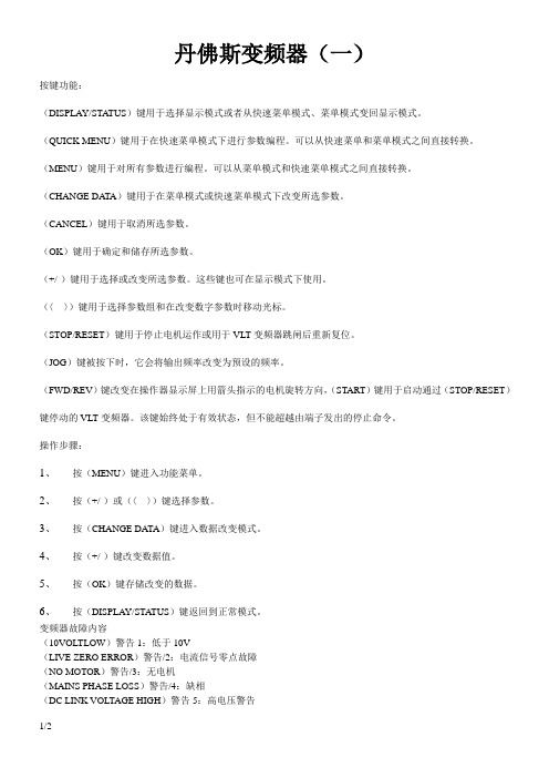
丹佛斯变频器(一)按键功能:(DISPLAY/STA TUS)键用于选择显示模式或者从快速菜单模式、菜单模式变回显示模式。
(QUICK MENU)键用于在快速菜单模式下进行参数编程。
可以从快速菜单和菜单模式之间直接转换。
(MENU)键用于对所有参数进行编程。
可以从菜单模式和快速菜单模式之间直接转换。
(CHANGE DA TA)键用于在菜单模式或快速菜单模式下改变所选参数。
(CANCEL)键用于取消所选参数。
(OK)键用于确定和储存所选参数。
(+/-)键用于选择或改变所选参数。
这些键也可在显示模式下使用。
(〈〉)键用于选择参数组和在改变数字参数时移动光标。
(STOP/RESET)键用于停止电机运作或用于VLT变频器跳闸后重新复位。
(JOG)键被按下时,它会将输出频率改变为预设的频率。
(FWD/REV)键改变在操作器显示屏上用箭头指示的电机旋转方向,(START)键用于启动通过(STOP/RESET)键停动的VLT变频器。
该键始终处于有效状态,但不能超越由端子发出的停止命令。
操作步骤:1、按(MENU)键进入功能菜单。
2、按(+/-)或(〈〉)键选择参数。
3、按(CHANGE DATA)键进入数据改变模式。
4、按(+/-)键改变数据值。
5、按(OK)键存储改变的数据。
6、按(DISPLAY/STATUS)键返回到正常模式。
变频器故障内容(10VOLTLOW)警告1:低于10V(LIVE ZERO ERROR)警告/2:电流信号零点故障(NO MOTOR)警告/3:无电机(MAINS PHASE LOSS)警告/4:缺相(DC LINK VOLTAGE HIGH)警告5:高电压警告(DC LINK VOLTAGELOW)警告6:低电压警告(DC LINK OVERVOLT)警告7:过电压(DC LINK UNDERVOLT)警告/8:欠电压(INVERTER TIME)警告/9:逆变器过载(MOTOR TIME)警告/10:电机温度过高(MOTOR THERMISTOR)警告/11:电机过热(热敏电阻)(TORQUE LIMIT)警告/12:过转矩极限(OVERCURRENT)警告/13:过电流(EARTH FAULT)14:接地电流(SWITCH MODE FAULT)15:载波模式故障(CURR.SHORT CIRCUIT)16:短路(STD BUSTIMEOUT)警告/17:总线无信号(HPFB BUS TIMEOUT)警告/18:HPFB总线无信号(EE ERROR POWER CARD)警告19:电源卡EEPROM故障(EE ERROR CTRL CARD)警告20:控制卡EEPROM故障(AUTO MOTOR ADAPT OK)21:自动适配正常(BRAKE TEST FAILED)警告和22:制动核查中的故障(BRAKE RESISTOR FAULT)警告23:制动电阻故障(BRAKE PWR WARN 100%)警告24:制动电阻率100% (BRAKE IGBT FAULT)警告25:制动晶体管故障(HEAT SINK OVER TEMP)警告26:散热器温度过高(MISSING MOT.PHASEU)27:电机U相缺失(MISSING MOT.PHASE V)28:电机V相缺失(MISSING MOT.PHASE W)29:电机W相缺失(QUICK DISCHARGE NOT OK)30:快速放电不正常。
丹佛斯变频器操作说明

韻㈣解观8 W *世幽鸽敷醐敝翻的聘擱⅛ (9NlNaVM)号哥(NO)财醃骗临的馳g≡ £中¾≡桦黜躺冀•豳釧幅劉懾e≡辭屋SO蜩鮒罪“巾昭Iil翹钿。
i⅛i⅛≡≡ι £[⅛ι^≡^≡ P 坐般鼬* Iim i≡i2,½≡δ⅛⅛ P 购鶴S≡ 釧≡'s 馳轿T≡ E 翩她≡S Z豐M I≈msι^≡⅛f∣•MK UJε 卿∏Λ播弼释牖題離鵬虞■刪圈擱進说辭Oi搁韓ΠΛKfeft删胁(S 8®跚搁)Q ■鶴搁H-認虫鱷麵口A≡3≡dσι ■■讀示屏聶LCD 删俪■ T IfflWSg!W* Ii示髓≡ra瀬/融中謬。
■瀏獗删勰分衲別细分按漑於濃騎模琳鯛參決τaι≡8smw≡ *第-厅用任持飜示操作临下SEIB鉤賊說明磯二行揀示8≡)證“第二厅前了齣或谿2那任畝況下牒爾⅛sss≡≡t≡*第三行-曲空白■它用於騎馨軾下腿细號嶋輔鮒细組頼挪*瓢厅用於弔那軾下騎般文字或側翱據軾下騎鱷细的勲或麴≡ •箭頭騎髓躋方向、並且同髒示在麴004癮鹏殡疽肄釦齡:俵勒炖肄临訓和擢劇騎於石方並閃動。
IDlSPLAY/STATUS]可選離禱蹶做凝單或義輾趣骐腮,[QUICK MENU]可症入険表軍麴-也可在驱表艱表範髒珑≡f簸iIMENuI丸丽勺礪參執也巧描及快港肄2髓»•第-行口⅛Ξfj 輒行[CHANGE DATA]可更改戎單或快逸表單⅞M式下所選擇的設定* [CANCEL]取消史改選迁:的蔘數設定- [OKJ砖認選丄參數的車改SS定4[÷A]用於選擇或改翌所選蔘数• [<>]用於選擇蔘數組和在改變數字値參戟時移動光嘿-[STOpyRESETJ可用於停止馬達連作或便愛頻器跳脫後重新幺訓祗注皂幸小014 ^⅛'2..√1⅛√Λ:7/ [STOP; RESET]淤握匸勻效狀態下按下此鍵後第二行顯示將會閃爍* [JCX3]可用於將晦出頻率改矍為頊設旳頻率(寸動頻率)。
丹佛斯变频器说明书
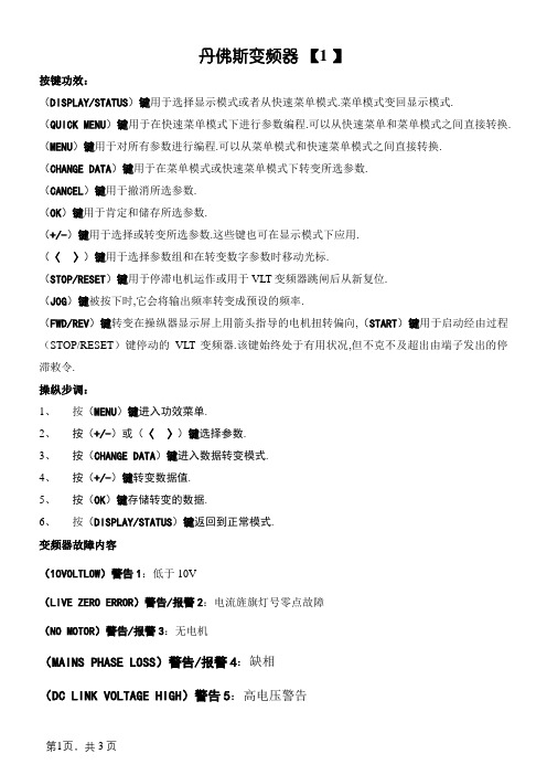
丹佛斯变频器【1 】按键功效:(DISPLAY/STATUS)键用于选择显示模式或者从快速菜单模式.菜单模式变回显示模式.(QUICK MENU)键用于在快速菜单模式下进行参数编程.可以从快速菜单和菜单模式之间直接转换. (MENU)键用于对所有参数进行编程.可以从菜单模式和快速菜单模式之间直接转换.(CHANGE DATA)键用于在菜单模式或快速菜单模式下转变所选参数.(CANCEL)键用于撤消所选参数.(OK)键用于肯定和储存所选参数.(+/-)键用于选择或转变所选参数.这些键也可在显示模式下应用.(〈〉)键用于选择参数组和在转变数字参数时移动光标.(STOP/RESET)键用于停滞电机运作或用于VLT变频器跳闸后从新复位.(JOG)键被按下时,它会将输出频率转变成预设的频率.(FWD/REV)键转变在操纵器显示屏上用箭头指导的电机扭转偏向,(START)键用于启动经由过程(STOP/RESET)键停动的VLT变频器.该键始终处于有用状况,但不克不及超出由端子发出的停滞敕令.操纵步调:1、按(MENU)键进入功效菜单.2、按(+/-)或(〈〉)键选择参数.3、按(CHANGE DATA)键进入数据转变模式.4、按(+/-)键转变数据值.5、按(OK)键存储转变的数据.6、按(DISPLAY/STATUS)键返回到正常模式.变频器故障内容(10VOLTLOW)警告1:低于10V(LIVE ZERO ERROR)警告/报警2:电流旌旗灯号零点故障(NO MOTOR)警告/报警3:无电机(MAINS PHASE LOSS)警告/报警4:缺相(DC LINK VOLTAGE HIGH)警告5:高电压警告(DC LINK VOLTAGELOW)警告6:低电压警告(DC LINK OVERVOLT)警告7:过电压(DC LINK UNDERVOLT)警告/报警8:欠电压(INVERTER TIME)警告/报警9:逆变器过载(MOTOR TIME)警告/报警10:电机温渡过高(MOTOR THERMISTOR)警告/报警11:电机过热(热敏电阻)(TORQUE LIMIT)警告/报警12:过转矩极限(OVERCURRENT)警告/报警13:过电流(EARTH FAULT)报警14:接地电流(SWITCH MODE FAULT)报警15:载波模式故障(CURR.SHORT CIRCUIT)报警16:短路(STD BUSTIMEOUT)警告/报警17:尺度总线无旌旗灯号(HPFB BUS TIMEOUT)警告/报警18:HPFB总线无旌旗灯号(EE ERROR POWER CARD)警告19:电源卡EEPROM故障(EE ERROR CTRL CARD)警告20:掌握卡EEPROM故障(AUTO MOTOR ADAPT OK)报警21:主动适配正常(BRAKE TEST FAILED)警告和报警22:制动核查中的故障(BRAKE RESISTOR FAULT)警告23:制动电阻故障(BRAKE PWR WARN 100%)警告24:制动电阻率100%(BRAKE IGBT FAULT)警告25:制动晶体管故障(HEAT SINK OVER TEMP)警告26:散热器温渡过高(MISSING MOT.PHASEU)报警27:电机U相缺掉(MISSING MOT.PHASE V)报警28:电机V相缺掉(MISSING MOT.PHASE W)报警29:电机W相缺掉(QUICK DISCHARGE NOT OK)报警30:快速放电不正常。
VLT Micro Drive FC 51 Operating Instructions
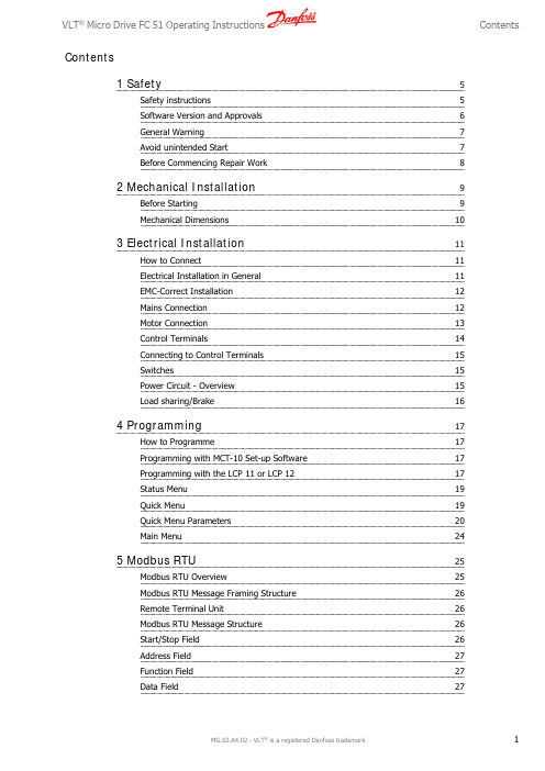
Contents1 Safety5Safety instructions5Software Version and Approvals6General Warning7Avoid unintended Start7Before Commencing Repair Work82 Mechanical Installation9Before Starting9Mechanical Dimensions103 Electrical Installation11How to Connect11Electrical Installation in General11EMC-Correct Installation12Mains Connection12Motor Connection13Control Terminals14Connecting to Control Terminals15Switches15Power Circuit - Overview15Load sharing/Brake164 Programming17How to Programme17Programming with MCT-10 Set-up Software17Programming with the LCP 11 or LCP 1217Status Menu19Quick Menu19Quick Menu Parameters20Main Menu245 Modbus RTU25Modbus RTU Overview25Modbus RTU Message Framing Structure26Remote Terminal Unit26Modbus RTU Message Structure26Start/Stop Field26Address Field27Function Field27Data Field27CRC Check Field27 Coil/Register Addressing27 How to Control the frequency converter29 Function Codes Supported by Modbus RTU29 Exception and Error Codes29 How to Access Parameters30 Parameter Handling30 Storage of Data30 IND30 Text Blocks30 Conversion Factor30 Parameter Values30 Examples30 Read Coil Status (01HEX)31 Force/Write Single Coil (05HEX)31 Force/Write Multiple Coils (0F HEX)32 Read Holding Registers (03HEX)32 Preset Single Register (06HEX)33 Preset Multiple Registers (10HEX)34 Danfoss FC Control Profile35 Control Word According to FC Profile35 Explanation of the Control Bits35 Status Word According to FC Profile (STW)37 Explanation of the Status Bits38 Bus Speed Reference Value396 Parameter Overview41Conversion Index45 Change during operation45 2-Set-up45 Type45 0-** Operation/Display46 1-** Load/Motor47 2-** Brakes48 3-** Reference/Ramps49 4-** Limits/Warnings50 5-** Digital In/Out51 6-** Analog In/Out52 7-** Controllers53 8-** Comm. and Options54 13-** Smart Logic5514-** Special Functions56 15-** Drive Information57 16-** Data Readouts587 Troubleshooting59Alarm, Warning and Extended Status Word608 Specifications61Mains Supply61 Other Specifications63 Special Conditions65 The Purpose of Derating65 Derating for Ambient Temperature65 Derating for Low Air Pressure65 Derating for Running at Low Speeds65 Options for VLT Micro Drive FC 5166Index67111.1.1High Voltage WarningThe voltage of the frequency converter is dangerous whenever it is connected to mains. Incorrect installation of the motor or frequency converter may cause damage to the equipment, serious injury or death. Consequently, it is essential to comply with the instructionsin this manual as well as local and national rules and safety regulations.1.1.2Safety instructionsPrior to using functions directly or indirectly influencing personal safety (e.g. Safe Stop , Fire Mode or other functions either forcing the motor to stop or attempting to keep it functioning) a thorough risk analysis and system test must be carried through. The system tests must include testing failure modes regarding the control signalling (analog and digital signals and serial communication.NB!Before using Fire Mode, contact Danfoss•Make sure the frequency converter is properly connected to earth.•Do not remove mains connections, motor connections or other power connections while the frequency converter is connected to power.•Protect users against supply voltage.•Protect the motor against overloading according to national and local regulations.•The earth leakage current exceeds 3.5 mA.•The [OFF] key is not a safety switch. It does not disconnect the frequency converter from mains.11.1.3Software Version and ApprovalsSoftware VersionOperating InstructionsVLT Micro DriveFC 51 SeriesThis Operating Instructionscan be used for all VLT MicroDrive FC 51 frequency con-verters with software version2.2x.The software version numbercan be read inparameter 15-43.11.1.4General WarningWarning:Touching the electrical parts may be fatal - even after the equipment has been disconnected from mains.Also make sure that other voltage inputs have been disconnected (linkage of DC intermediate circuit).Be aware that there may be high voltage on the DC link even when the LEDs are turned off.Before touching any potentially live parts of the frequency converter, wait at least 4 minutes for all sizes.Shorter time is allowed only if indicated on the nameplate for the specific unit.Leakage CurrentThe earth leakage current from the frequency converter exceeds 3.5 mA. According to IEC 61800-5-1 a reinforced Protective Earth connection must be ensured by means of a min. 10mm² Cu or an addtional PE wire - with the same cable cross section as the Mains wiring - must be terminated separately.Residual Current DeviceThis product can cause a DC current in the protective conductor. Where a residual current device (RCD) is used for extra protection,only an RCD of Type B (time delayed) shall be used on the supply side of this product. See also Danfoss Application Note on RCD, MN.90.GX.YY.Protective earthing of the frequency converter and the use of RCDs must always follow national and local regulations.Motor overload protection is possible by setting Parameter 1-90 Motor thermal protection to the value ETR trip. For the North Americanmarket: ETR functions provide class 20 motor overload protection, in accordance with NEC.Installation in high altitudes:For altitudes above 2 km, please contact Danfoss regarding PELV.1.1.5IT MainsIT MainsInstallation on isolated mains source, i.e. IT mains.Max. supply voltage allowed when connected to mains: 440 V.As an option, Danfoss offers line filters for improved harmonics performance.1.1.6Avoid unintended StartWhile the frequency converter is connected to mains, the motor can be started/stopped using digital commands, bus commands, references or via the Local Control Panel.•Disconnect the frequency converter from mains whenever personal safety considerations make it necessary to avoid unintended start of any motors.•To avoid unintended start, always activate the [OFF] key before changing parameters.11.1.7Disposal instructionEquipment containing electrical components must not be disposed of together with domestic waste.It must be separately collected with electrical and electronic waste according to local and currently valid leg-islation.1.1.8Before Commencing Repair Work1.Disconnect FC 51 from mains (and external DC supply, if present.)2.Wait for 4 minutes for discharge of the DC-link.3.Disconnect DC bus terminals and brake terminals (if present)4.Remove motor cable122.1Before Starting2.1.1ChecklistWhen unpacking the frequency converter, make sure that the unit is un-damaged and complete. Check that the packaging contains the following:•VLT Micro Drive FC 51•Quick GuideOptional: LCP and/or de-coupling plate.Illustration 2.1: Content of box.2.2Side-by-Side InstallationThe frequency converter can be mounted side-by-side for IP 20 rating units and requires 100 mm clearance above and below for cooling. Regarding surroundings in general, please see chapter 7. Specifications.Illustration 2.1: Side-by-side installation.VLT ® Micro Drive FC 51 Operating Instructions 2 Mechanical Installation22.3.1Mechanical DimensionsIllustration 2.1: Mechanical dimensions.NB!A template for drilling can be found on the flap of the packaging.Table 2.1: Mechanical Dimensions1) For LCP with potentiometer, please add 7.6 mm.NB!DIN rail mounting kit is available for M1 frame . Please use ordering number 132B0111.2 Mechanical Installation VLT ® Micro Drive FC 51 Operating Instructions233.1How to Connect3.1.1Electrical Installation in GeneralNB!All cabling must comply with national and local regulations on cable cross-sections and ambient temperature. Copper conductors required, (60-75° C) recommended.Table 3.1: Tightening of terminals.3.1.2FusesBranch circuit protection:In order to protect the installation against electrical and fire hazard, all branch circuits in an installation, switch gear, machines etc., must be short-circuited and overcurrent protected according to national/international regulations.Short circuit protection:Danfoss recommends using the fuses mentioned in the following tables to protect service personnel or other equipment in case of an internal failure in the unit or short-circuit on DC-link. The frequency converter provides full short circuit protection in case of a short-circuit on the motor or brake output.a circuit capable of supplying a maximum of 100,000 A rms (symmetrical), 480 V maximum.Overcurrent protection:Provide overload protection to avoid overheating of the cables in the installation. Overcurrent protection must always be carried out according to national regulations. Fuses must be designed for protection in a circuit capable of supplying a maximum of 100,000 A rms (symmetrical), 480 V maximum.Non UL compliance:If UL/cUL is not to be complied with, Danfoss recommends using the fuses mentioned in the below table, which will ensure compliance with EN50178/IEC61800-5-1:In case of malfunction, not following the fuse recommendation may result in damage to the frequency converter.VLT ® Micro Drive FC 51 Operating Instructions 3 Electrical Installation3Table 3.3: Fuses3.1.3EMC-Correct InstallationFollowing these guidelines is advised, where compliance with EN 61000-6-3/4, EN 55011 or EN 61800-3 First environment is required. If the installation is in EN 61800-3 Second environment , then it is acceptable to deviate from these guidelines. It is however not recommended.Good engineering practice to ensure EMC-correct electrical installation:•Use only braided screened/armoured motor cables and control cables.The screen should provide a minimum coverage of 80%.The screen material must be metal, not limited to but typically copper, aluminium, steel or lead. There are no special requirements for the mains cable.•Installations using rigid metal conduits are not required to use screened cable, but the motor cable must be installed in conduit separate from the control and mains cables. Full connection of the conduit from the drive to the motor is required. The EMC performance of flexible conduits varies a lot and information from the manufacturer must be obtained.•Connect the screen/armour/conduit to earth at both ends for motor cables and control cables.•Avoid terminating the screen/armour with twisted ends (pigtails). Such a termination increases the high frequency impedance of the screen,which reduces its effectiveness at high frequencies. Use low impedance cable clamps or glands instead.•Ensure good electrical contact between the de-coupling plate and the metal chassis of the frequency converter, see Instruction MI.02.BX.YY.•Avoid using unscreened/unarmoured motor or control cables inside cabinets housing the drive(s), where possible.3.2Mains Connection3.2.1Connecting to MainsStep 1: First mount earth cable.Step 2: Mount wires in terminals L1/L, L2 and L3/N and tighten.Illustration 3.1: Mounting of earth cable and mains wires.3 Electrical Installation VLT ® Micro Drive FC 51 Operating Instructions3For 3-phase connection, connect wires to all three terminals.For single-phase connection, connect wires to terminals L1/L and L3/N.Illustration 3.2: Three-phase and single-phase wire connections.3.3Motor Connection3.3.1How to Connect the MotorSee the chapter Specifications for correct dimensioning of motor cable cross-section and length.•Use a shielded/armored motor cable to comply with EMC emission specifications, and connect this cable to both the decoupling plate and the motor metal.•Keep motor cable as short as possible to reduce the noise level and leakage currents.For further details on mounting of the decoupling plate, please see instruction MI.02.BX.YY.All types of three-phased asynchronous standard motors can be connec-ted to the frequency converter. Normally, small motors are star-connec-ted (230/400 V, Δ/Y). Large motors are delta-connected (400/690 V, Δ/Y). Refer to motor nameplate for correct connection and voltage.Illustration 3.3: Star and delta connections.Step 1: First, mount the earth cable.Step 2: Connect wires to terminals either in star or delta-connection. Seemotor nameplate for further information.Illustration 3.4: Mounting of earth cable and motor wires.VLT ® Micro Drive FC 51 Operating Instructions3 Electrical Installation3For EMC correct installation, use optional de-coupling plate, see chapter Options for frequency converter.Illustration 3.5: Frequency converter with de-coupling plate3.4Control Terminals3.4.1Access to Control TerminalsAll control cable terminals are located underneath the terminal cover infront of the frequency converter. Remove the terminal cover using ascrewdriver.Illustration 3.6: Removing terminal cover.NB!See back of terminal cover for outlines of control terminals and switches.3 Electrical Installation VLT® Micro Drive FC 51 Operating Instructions 33.4.2Connecting to Control TerminalsThis illustration shows all control terminals of the frequency converter. Applying Start (term. 18) and an analog reference (term. 53 or 60) make thefrequency converter run.Illustration 3.7: Overview of control terminals in PNP-configuration and factory setting.3.5SwitchesNB!Do not operate switches with power on the frequency converter.Bus termination:Switch BUS TER pos. ON terminates the RS485 port, terminals 68, 69.See power circuit drawing.Default setting = Off.Illustration 3.8: S640 Bus termination.S200 Switches 1-4:Table 3.5: Settings for S200 Switches 1-4Illustration 3.9: S200 Switches 1-4.NB!Parameter 6-19 must be set according to Switch 4 po-sition.VLT ® Micro Drive FC 51 Operating Instructions3 Electrical Installation33.6Power Circuit - Overview3.6.1Power Circuit - OverviewIllustration 3.10: Diagram showing all electrical terminals.Brake not applicable for frame M1.Brake resistors are available from Danfoss.Improved power factor and EMC performance can be achieved by installing optional Danfoss line filters.Danfoss power filters can also be used for load sharing.3.6.2Load sharing/BrakeUse 6.3 mm insulated Faston Plugs designed for high voltage for DC (Load Sharing and brake).Contact Danfoss or see instruction no. MI.50.Nx.02 for load sharing and instruction no. MI.90.Fx.02 for brake.Load sharing: Connect terminals UDC- and UDC/BR+.Brake: Connect terminals BR- and UDC/BR+.Note that voltage levels of up to 850 V DC may occur between terminals UDC+/BR+ and UDC-. Not short circuit protected.3 Electrical Installation VLT ® Micro Drive FC 51 Operating Instructions344.1How to Programme4.1.1Programming with MCT-10 Set-up SoftwareThe frequency converter can be programmed from a PC via RS485 com-port by installing the MCT-10 Set-up Software.This software can either be ordered using code number 130B1000 or downloaded from the Danfoss Web site: , Business Area: Motion Controls.Please refer to manual MG.10.RX.YY.4.1.2Programming with the LCP 11 or LCP 12The LCP is divided into four functional groups:1.Numeric display.2.Menu key.3.Navigation keys.4.Operation keys and indicator lights (LEDs).Illustration 4.1: LCP 12 with potentiometer Illustration 4.2: LCP 11 without potentiometerThe display:A number of information can be read from the display.Set-up number shows the active set-up and the edit set-up. If the same set-up acts as both active and edit set-up, only that set-up number is shown (factory setting).When active and edit set-up differ, both numbers are shown in the display(Setup 12). The number flashing, indicates the edit set-up.Illustration 4.3: Indicating Set-upVLT ® Micro Drive FC 51 Operating Instructions 4 Programming4The small digits to the left are the selected parameter number.Illustration 4.4: Indicating selected par. no.The large digits in the middle of the display show the value of the se-lected parameter.Illustration 4.5: Indicating value of selected par.The right side of the display shows the unit of the selected parameter.This can be either Hz, A, V, kW, HP, %, s or RPM.Illustration 4.6: Indicating unit of selected par.Motor direction is shown to the bottom left of the display - indicatedby a small arrow pointing either clockwise or counterclockwise.Illustration 4.7: Indicating motor directionUse the [MENU] key to select one of the following menus:Status Menu:The Status Menu is either in Readout Mode or Hand on Mode . In Readout Mode the value of the currently selected readout parameter is shown in the display.In Hand on Mode the local LCP reference is displayed.Quick Menu:Displays Quick Menu parameters and their settings. Parameters in the Quick Menu can be accessed and edited from here. Most applications can be run by setting the parameters in the Quick Menus.Main Menu:Displays Main Menu parameters and their settings. All parameters can be accessed and edited here. A parameter overview is found later in this manual.Indicator lights:•Green LED: The frequency converter is on.•Yellow LED: Indicates a warning. Please see section Troubleshooting •Flashing red LED: Indicates an alarm. Please see section Troubleshooting4 ProgrammingVLT ® Micro Drive FC 51 Operating Instructions4Navigation Keys:[Back]: For moving to the previous step or layer in the navigation structure.Arrows [▲] [▼]: For maneuvering between parameter groups, parameters and within parameters.[OK]: For selecting a parameter and for accepting changes to parameter settings.Operation Keys:A yellow light above the operation keys indicates the active key.[Hand on]: Starts the motor and enables control of the frequency converter via the LCP.[Off/Reset]: The motor stops except in alarm mode. In that case the motor will be reset.[Auto on]: The frequency converter is controlled either via control terminals or serial communication.[Potentiometer] (LCP12): The potentiometer works in two ways depending on the mode in which the frequency converter is running.In Auto Mode the potentiometer acts as an extra programmable analog input.In Hand on Mode the potentiometer controls local reference.4.2Status MenuAfter power up the Status Menu is active. Use the [MENU] key to toggle between Status, Quick Menu and Main Menu.Arrows [▲] and [▼] toggles between the choices in each menu.The display indicates the status mode with a small arrow above “Status”.Illustration 4.8: Indicating Status mode4.3Quick MenuThe Quick Menu gives easy access to the most frequently used parameters.1.To enter the Quick Menu, press [MENU] key until indicator in display is placed above Quick Menu .e [▲] [▼] to select either QM1 or QM2, then press [OK].e [▲] [▼] to browse through the parameters in the Quick Menu.4.Press [OK] to select a parameter.e [▲] [▼] to change the value of a parameter setting.6.Press [OK] to accept the change.7.To exit, press either [Back] twice to enter Status , or press [Menu] once to enter Main Menu.Illustration 4.9: Indicating Quick Menu modeVLT ® Micro Drive FC 51 Operating Instructions4 Programming44.4Quick Menu Parameters4.4.1Quick Menu Parameters - Basic Settings QM1Below are descriptions of all parameters found in the Quick Menu.* = Factory setting.Option:Function:Enter motor power from nameplate data.Two sizes down, one size up from nominal VLT rating.[1]0.09 kW/0.12 HP [2]0.12 kW/0.16 HP [3]0.18kW/0.25 HP [4]0.25 kW/0.33 HP [5]0.37kW/0.50 HP [6]0.55 kW/0.75 HP [7]0.75 kW/1.00 HP [8] 1.10 kW/1.50 HP [9] 1.50 kW/2.00 HP [10] 2.20 kW/3.00 HP [11] 3.00 kW/4.00 HP [12] 3.70 kW/5.00 HP [13] 4.00 kW/5.40 HP [14] 5.50 kW/7.50 HP [15]7.50 kW/10.0 HP [16]11.00 kW/15.00 HPNB!Changing this parameter affects par. 1-22 to 1-25,1-30, 1-33 and 1-35.m.n )Range:Function:230/400 V [50 - 999 V]Enter motor voltage from nameplate data.m.n )Range:Function:50 Hz*[20-400 Hz]Enter motor frequency from nameplate data.4 Programming VLT ® Micro Drive FC 51 Operating Instructions4M-type de-pendent*[0.01 - 26.00 A]Enter motor current from nameplate data.Range:Function:M-type De-pendent*[100 - 9999 RPM]Enter motor nominal speed from nameplate data.Option:Function:Use AMT to optimize motor performance.NB!This parameter cannot be changed while motor runs.1.Stop the frequency converter – make sure motor is at standstill2.Choose [2] Enable AMT3.Apply start signal – Via LCP: Press Hand On- Or in Remote On mode: Apply start signal on terminal 18[0] *Off AMT function is disabled.[2]Enable AMTAMT function starts running.NB!To gain optimum tuning of frequency converter, run AMT on a cold motor.Range:Function:0.00*[-4999 - 4999]Enter value for minimum reference.The sum of all internal and external references are clamped (limited) to the minimum reference value, par. 3-02.Range:Function:Maximum Reference is adjustable in the range Minimum Reference - 4999.50.00*[-4999 - 4999]Enter value for Maximum Reference.The sum of all internal and external references are clamped (limited) to the maximum reference value, par. 3-03.43.00 s* [0.05 - 3600.00 s ]Enter ramp-up time from 0 Hz to rated motor frequency (f M,N) set in par. 1-23.Choose a ramp-up time ensuring that torque limit is not exceeded, see par. 4-16.Range:Function:3.00* [0.05 - 3600.00 s]Enter ramp down time from rated motor frequency (f M,N) in par. 1-23 to 0 Hz.Choose a ramp down time that does not cause over-voltage in inverter due to regenerative operationof motor. Furthermore, regenerative torque must not exceed limit set in par. 4-17.4.4.2Quick Menu Parameters - PI Basic Settings QM2The following is a brief description of the parameters for the PI Basic Settings. For a more detailed description, please see VLT Micro Drive Programming Guide, MG.02.CX.YY.Range:Function:[]Choose [3] Process Closed LoopRange:Function:[-4999 - 4999]Sets limits for set-point and feedback.Range:Function:[-4999 - 4999]Sets limits for set-point and feedback.Range:Function:[-100.00 - 100.00]Preset [0] works as set-point.Range:Function:[0.0 - 400 Hz]Lowest possible output frequency.Range:Function:[0.0 - 400.00 Hz]Highest possible output frequency.NB!Default 65 Hz should normally be reduced to 50 - 55 Hz.4[0.00 - 19.99 mA]Normally set to 0 or 4 mA.Range:Function:[0.01 - 20.00 mA]Normally (default) set to 20 mA.4 Range:Function:[-4999 - 4999]Value corresponding to P. 6-22 setting.Range:Function:[-4999 - 4999]Value corresponding to P. 6-23 setting.Range:Function:[0.01 - 10.00 s]Filter for suppressing electrical noise.Range:Function:[]Choose [2] analog input 60.Range:Function:[]Most PI controllers are “Normal”.Range:Function:[]Leave Enabled normally.Range:Function:[0.0 - 200.0 Hz]Choose expected normal running speed.Range:Function:[0.00 - 10.00]Enter the P-factor.Range:Function:[0.10 - 9999.00 s]Enter the I-factor.[0 - 400%]Only applicable with changing set-points.4.5Main MenuThe Main Menu gives access to all parameters.1.To enter the Main Menu, press [MENU] key until indicator indisplay is placed above Main Menu.e [▲] [▼] to browse through the parameter groups.3.Press [OK] to select a parameter group.e [▲] [▼] to browse through the parameters in the specificgroup.5.Press [OK] to select the parameter.e [▲] [▼] to set/change the parameter value.7.Press [OK] to accept the value.8.To exit, press either [Back] twice to enter Quick Menu, or press[Menu] once to enter Status.Illustration 4.10: Indicating Main Menu mode45 5.1Modbus RTU Overview5.1.1AssumptionsThese operating instructions assume that the installed controller supports the interfaces in this document and that all the requirements stipulated in the controller, as well as the frequency converter, are strictly observed, along with all limitations therein.5.1.2What the User Should Already KnowThe Modbus RTU (Remote Terminal Unit) is designed to communicate with any controller that supports the interfaces defined in this document. It is assumed that the user has full knowledge of the capabilities and limitations of the controller.5.1.3Modbus RTU OverviewRegardless of the type of physical communication networks, the Modbus RTU Overview describes the process a controller uses to request access to another device. This includes i.a. how it will respond to requests from another device, and how errors will be detected and reported. It also establishes a common format for the layout and contents of message fields.During communications over a Modbus RTU network, the protocol determines how each controller will learn its device address, recognise a message addressed to it, determine the kind of action to be taken, and extract any data or other information contained in the message. If a reply is required, the controller will construct the reply message and send it.Controllers communicate using a master-slave technique in which only one device (the master) can initiate transactions (called queries). The other devices (slaves) respond by supplying the requested data to the master, or by taking the action requested in the query.The master can address individual slaves, or can initiate a broadcast message to all slaves. Slaves return a message (called a response) to queries that are addressed to them individually. No responses are returned to broadcast queries from the master. The Modbus RTU protocol establishes the format for the master’s query by placing into it the device (or broadcast) address, a function code defining the requested action, any data to be sent, and an error-checking field. The slave’s response message is also constructed using Modbus protocol. It contains fields confirming the action taken, any data to be returned, and an error-checking field. If an error occurs in receipt of the message, or if the slave is unable to perform the requested action, the slave will construct an error message and send it in response, or a time-out will occur.5.1.4Frequency Converter with Modbus RTUThe frequency converter communicates in Modbus RTU format over the built-in RS-485 interface. Modbus RTU provides access to the Control Word and Bus Reference of the frequency converter.The Control Word allows the Modbus master to control several important functions of the frequency converter:•Start•Stop of the frequency converter in various ways:Coast stop Quick stop DC Brake stop Normal (ramp) stop •Reset after a fault trip•Run at a variety of preset speeds •Run in reverse•Change the active set-up•Control the frequency converter’s built-in relayThe Bus Reference is commonly used for speed control. It is also possible to access the parameters, read their values, and where possible, write values to them. This permits a range of control options, including controlling the setpoint of the frequency converter when its internal PI controller is used.5。
丹佛斯变频器说明书

丹佛斯变频器按键功能:(DISPLAY/STATUS)键用于选择显示模式或者从快速菜单模式、菜单模式变回显示模式。
(QUICK MENU)键用于在快速菜单模式下进行参数编程。
可以从快速菜单和菜单模式之间直接转换。
(MENU)键用于对所有参数进行编程。
可以从菜单模式和快速菜单模式之间直接转换。
(CHANGE DATA)键用于在菜单模式或快速菜单模式下改变所选参数。
(CANCEL)键用于取消所选参数。
(OK)键用于确定和储存所选参数。
(+/-)键用于选择或改变所选参数。
这些键也可在显示模式下使用。
(〈〉)键用于选择参数组和在改变数字参数时移动光标。
(STOP/RESET)键用于停止电机运作或用于VLT变频器跳闸后重新复位。
(JOG)键被按下时,它会将输出频率改变为预设的频率。
(FWD/REV)键改变在操作器显示屏上用箭头指示的电机旋转方向,(START)键用于启动通过(STOP/RESET)键停动的VLT变频器。
该键始终处于有效状态,但不能超越由端子发出的停止命令。
操作步骤:1、按(MENU)键进入功能菜单。
2、按(+/-)或(〈〉)键选择参数。
3、按(CHANGE DATA)键进入数据改变模式。
4、按(+/-)键改变数据值。
5、按(OK)键存储改变的数据。
6、按(DISPLAY/STATUS)键返回到正常模式。
变频器故障内容(10VOLTLOW)警告1:低于10V(LIVE ZERO ERROR)警告/报警2:电流信号零点故障(NO MOTOR)警告/报警3:无电机(MAINS PHASE LOSS)警告/报警4:缺相(DC LINK VOLTAGE HIGH)警告5:高电压警告(DC LINK VOLTAGELOW)警告6:低电压警告(DC LINK OVERVOLT)警告7:过电压(DC LINK UNDERVOLT)警告/报警8:欠电压(INVERTER TIME)警告/报警9:逆变器过载(MOTOR TIME)警告/报警10:电机温度过高(MOTOR THERMISTOR)警告/报警11:电机过热(热敏电阻)(TORQUE LIMIT)警告/报警12:过转矩极限(OVERCURRENT)警告/报警13:过电流(EARTH FAULT)报警14:接地电流(SWITCH MODE FAULT)报警15:载波模式故障(CURR.SHORT CIRCUIT)报警16:短路(STD BUSTIMEOUT)警告/报警17:标准总线无信号(HPFB BUS TIMEOUT)警告/报警18:HPFB总线无信号(EE ERROR POWER CARD)警告19:电源卡EEPROM故障(EE ERROR CTRL CARD)警告20:控制卡EEPROM故障(AUTO MOTOR ADAPT OK)报警21:自动适配正常(BRAKE TEST FAILED)警告和报警22:制动核查中的故障(BRAKE RESISTOR FAULT)警告23:制动电阻故障(BRAKE PWR WARN 100%)警告24:制动电阻率100%(BRAKE IGBT FAULT)警告25:制动晶体管故障(HEAT SINK OVER TEMP)警告26:散热器温度过高(MISSING MOT.PHASEU)报警27:电机U相缺失(MISSING MOT.PHASE V)报警28:电机V相缺失(MISSING MOT.PHASE W)报警29:电机W相缺失(QUICK DISCHARGE NOT OK)报警30:快速放电不正常。
丹佛斯变频器说明书
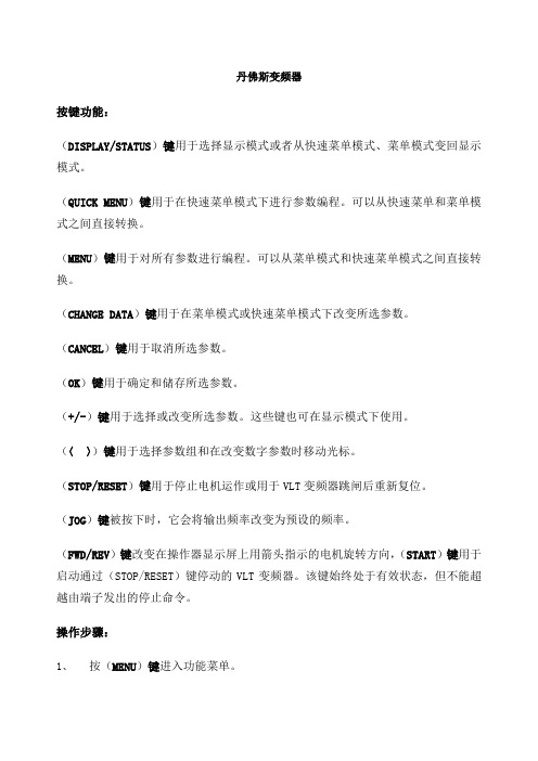
丹佛斯变频器按键功能:(DISPLAY/STATUS)键用于选择显示模式或者从快速菜单模式、菜单模式变回显示模式。
(QUICK MENU)键用于在快速菜单模式下进行参数编程。
可以从快速菜单和菜单模式之间直接转换。
(MENU)键用于对所有参数进行编程。
可以从菜单模式和快速菜单模式之间直接转换。
(CHANGE DATA)键用于在菜单模式或快速菜单模式下改变所选参数。
(CANCEL)键用于取消所选参数。
(OK)键用于确定和储存所选参数。
(+/-)键用于选择或改变所选参数。
这些键也可在显示模式下使用。
(〈〉)键用于选择参数组和在改变数字参数时移动光标。
(STOP/RESET)键用于停止电机运作或用于VLT变频器跳闸后重新复位。
(JOG)键被按下时,它会将输出频率改变为预设的频率。
(FWD/REV)键改变在操作器显示屏上用箭头指示的电机旋转方向,(START)键用于启动通过(STOP/RESET)键停动的VLT变频器。
该键始终处于有效状态,但不能超越由端子发出的停止命令。
操作步骤:1、按(MENU)键进入功能菜单。
2、按(+/-)或(〈〉)键选择参数。
3、按(CHANGE DATA)键进入数据改变模式。
4、按(+/-)键改变数据值。
5、按(OK)键存储改变的数据。
6、按(DISPLAY/STATUS)键返回到正常模式。
变频器故障内容(10VOLTLOW)警告1:低于10V(LIVE ZERO ERROR)警告/报警2:电流信号零点故障(NO MOTOR)警告/报警3:无电机(MAINS PHASE LOSS)警告/报警4:缺相(DC LINK VOLTAGE HIGH)警告5:高电压警告(DC LINK VOLTAGELOW)警告6:低电压警告(DC LINK OVERVOLT)警告7:过电压(DC LINK UNDERVOLT)警告/报警8:欠电压(INVERTER TIME)警告/报警9:逆变器过载(MOTOR TIME)警告/报警10:电机温度过高(MOTOR THERMISTOR)警告/报警11:电机过热(热敏电阻)(TORQUE LIMIT)警告/报警12:过转矩极限(OVERCURRENT)警告/报警13:过电流(EARTH FAULT)报警14:接地电流(SWITCH MODE FAULT)报警15:载波模式故障( CIRCUIT)报警16:短路(STD BUSTIMEOUT)警告/报警17:标准总线无信号(HPFB BUS TIMEOUT)警告/报警18:HPFB总线无信号(EE ERROR POWER CARD)警告19:电源卡EEPROM故障(EE ERROR CTRL CARD)警告20:控制卡EEPROM故障(AUTO MOTOR ADAPT OK)报警21:自动适配正常(BRAKE TEST FAILED)警告和报警22:制动核查中的故障(BRAKE RESISTOR FAULT)警告23:制动电阻故障(BRAKE PWR WARN 100%)警告24:制动电阻率100%(BRAKE IGBT FAULT)警告25:制动晶体管故障(HEAT SINK OVER TEMP)警告26:散热器温度过高(MISSING 报警27:电机U相缺失(MISSING V)报警28:电机V相缺失(MISSING W)报警29:电机W相缺失(QUICK DISCHARGE NOT OK)报警30:快速放电不正常。
丹弗斯FC51快速指南

1.1.1.1.相关文献注意本快速指南包含安装和运行 VLT Micro 变频器而所需的基本信息。
如果需要更多信息,您可以从下述位置下载相关的文献:/BusinessAreas/DrivesSolutions/Documentations/Technical+Documentation.htm 。
X = 修订号Y = 语言代码1.1.2.高压警告连接到主电源时,变频器带有危险电压。
如果电动机或变频器安装不当,可能导致设备损坏甚至人身伤亡。
因此,必须遵守本手册的说明以及国家和地方的规章和安全规定。
1.1.3.安全说明•确保变频器已正确接地。
•当变频器同电源相连时,请勿拔掉主电源插头、电动机插头或其它电源插头。
•防止用户接触供电电压。
•按照国家和地方法规进行电动机过载保护。
•接地漏电电流大于 3.5 mA。
•[OFF](停止)键不是安全开关。
它不能将变频器与主电源断开。
1.1.4.认证VLT Micro FC 51 快速指南 1. 快速指南MG.02.B2.41 - VLT ® 是 Danfoss 的注册商标111.1.5.一般警告警告:即使设备已断开与主电源的连接,触碰电气部件也可能会导致生命危险。
此外还应确保其它电压输入也已经断开(直流中间电路的连接)。
请注意,即使 LED 熄灭,直流回路上也可能存在高压。
在接触 VLT Micro Drive 的任何可能带电部分之前,对于所有规格,请等待至少 4分钟的时间。
仅当特定设备的铭牌上规定了更短的等待时间,才允许更短的时间。
漏电电流VLT Micro Drive FC 51 的接地漏电电流超过 3.5 mA。
根据 IEC 61800-5-1 的要求,必须借助下述方式来增强保护性接地:横截面积最小为 10mm• 的铜芯,或额外的 PE 线 - 其横截面积应与主电源电缆相同 - 必须单独终接。
漏电断路器该设备可在保护性导体中产生直流电流。
当使用漏电断路器 (RCD) 提供其他保护措施时,在本产品的输入端只能使用 B 类的 RCD(延时型)。
丹佛斯变频器说明书

丹佛斯变频器按键功能:(DISPLAY/STATUS)键用于选择显示模式或者从快速菜单模式、菜单模式变回显示模式。
(QUICK MENU)键用于在快速菜单模式下进行参数编程。
可以从快速菜单和菜单模式之间直接转换。
(MENU)键用于对所有参数进行编程。
可以从菜单模式和快速菜单模式之间直接转换。
(CHANGE DATA)键用于在菜单模式或快速菜单模式下改变所选参数。
(CANCEL)键用于取消所选参数。
(OK)键用于确定和储存所选参数。
(+/-)键用于选择或改变所选参数。
这些键也可在显示模式下使用。
(〈〉)键用于选择参数组和在改变数字参数时移动光标。
(STOP/RESET)键用于停止电机运作或用于VLT变频器跳闸后重新复位。
(JOG)键被按下时,它会将输出频率改变为预设的频率。
(FWD/REV)键改变在操作器显示屏上用箭头指示的电机旋转方向,(START)键用于启动通过(STOP/RESET)键停动的VLT变频器。
该键始终处于有效状态,但不能超越由端子发出的停止命令。
操作步骤:1、按(MENU)键进入功能菜单。
2、按(+/-)或(〈〉)键选择参数。
3、按(CHANGE DATA)键进入数据改变模式。
4、按(+/-)键改变数据值。
5、按(OK)键存储改变的数据。
6、按(DISPLAY/STATUS)键返回到正常模式。
变频器故障内容(10VOLTLOW)警告1:低于10V(LIVE ZERO ERROR)警告/报警2:电流信号零点故障(NO MOTOR)警告/报警3:无电机(MAINS PHASE LOSS)警告/报警4:缺相(DC LINK VOLTAGE HIGH)警告5:高电压警告(DC LINK VOLTAGELOW)警告6:低电压警告(DC LINK OVERVOLT)警告7:过电压(DC LINK UNDERVOLT)警告/报警8:欠电压(INVERTER TIME)警告/报警9:逆变器过载(MOTOR TIME)警告/报警10:电机温度过高(MOTOR THERMISTOR)警告/报警11:电机过热(热敏电阻)(TORQUE LIMIT)警告/报警12:过转矩极限(OVERCURRENT)警告/报警13:过电流(EARTH FAULT)报警14:接地电流(SWITCH MODE FAULT)报警15:载波模式故障(CURR.SHORT CIRCUIT)报警16:短路(STD BUSTIMEOUT)警告/报警17:标准总线无信号(HPFB BUS TIMEOUT)警告/报警18:HPFB总线无信号(EE ERROR POWER CARD)警告19:电源卡EEPROM故障(EE ERROR CTRL CARD)警告20:控制卡EEPROM故障(AUTO MOTOR ADAPT OK)报警21:自动适配正常(BRAKE TEST FAILED)警告和报警22:制动核查中的故障(BRAKE RESISTOR FAULT)警告23:制动电阻故障(BRAKE PWR WARN 100%)警告24:制动电阻率100%(BRAKE IGBT FAULT)警告25:制动晶体管故障(HEAT SINK OVER TEMP)警告26:散热器温度过高(MISSING MOT.PHASEU)报警27:电机U相缺失(MISSING MOT.PHASE V)报警28:电机V相缺失(MISSING MOT.PHASE W)报警29:电机W相缺失(QUICK DISCHARGE NOT OK)报警30:快速放电不正常。
丹佛斯变频器说明书
丹佛斯变频器按键功能:(DISPLAY/STATUS)键用于选择显示模式或者从快速菜单模式、菜单模式变回显示模式。
(QUICK MENU)键用于在快速菜单模式下进行参数编程。
可以从快速菜单和菜单模式之间直接转换。
(MENU)键用于对所有参数进行编程。
可以从菜单模式和快速菜单模式之间直接转换。
(CHANGE DATA)键用于在菜单模式或快速菜单模式下改变所选参数。
(CANCEL)键用于取消所选参数。
(OK)键用于确定和储存所选参数。
(+/-)键用于选择或改变所选参数。
这些键也可在显示模式下使用。
(〈〉)键用于选择参数组和在改变数字参数时移动光标。
(STOP/RESET)键用于停止电机运作或用于VLT变频器跳闸后重新复位。
(JOG)键被按下时,它会将输出频率改变为预设的频率。
(FWD/REV)键改变在操作器显示屏上用箭头指示的电机旋转方向,(START)键用于启动通过(STOP/RESET)键停动的VLT变频器。
该键始终处于有效状态,但不能超越由端子发出的停止命令。
操作步骤:1、按(MENU)键进入功能菜单。
2、按(+/-)或(〈〉)键选择参数。
3、按(CHANGE DATA)键进入数据改变模式。
4、按(+/-)键改变数据值。
5、按(OK)键存储改变的数据。
6、按(DISPLAY/STATUS)键返回到正常模式。
变频器故障内容(10VOLTLOW)警告1:低于10V(LIVE ZERO ERROR)警告/报警2:电流信号零点故障(NO MOTOR)警告/报警3:无电机(MAINS PHASE LOSS)警告/报警4:缺相(DC LINK VOLTAGE HIGH)警告5:高电压警告(DC LINK VOLTAGELOW)警告6:低电压警告(DC LINK OVERVOLT)警告7:过电压(DC LINK UNDERVOLT)警告/报警8:欠电压(INVERTER TIME)警告/报警9:逆变器过载(MOTOR TIME)警告/报警10:电机温度过高(MOTOR THERMISTOR)警告/报警11:电机过热(热敏电阻)(TORQUE LIMIT)警告/报警12:过转矩极限(OVERCURRENT)警告/报警13:过电流(EARTH FAULT)报警14:接地电流(SWITCH MODE FAULT)报警15:载波模式故障( CIRCUIT)报警16:短路(STD BUSTIMEOUT)警告/报警17:标准总线无信号(HPFB BUS TIMEOUT)警告/报警18:HPFB总线无信号(EE ERROR POWER CARD)警告19:电源卡EEPROM故障(EE ERROR CTRL CARD)警告20:控制卡EEPROM故障(AUTO MOTOR ADAPT OK)报警21:自动适配正常(BRAKE TEST FAILED)警告和报警22:制动核查中的故障(BRAKE RESISTOR FAULT)警告23:制动电阻故障(BRAKE PWR WARN 100%)警告24:制动电阻率100%(BRAKE IGBT FAULT)警告25:制动晶体管故障(HEAT SINK OVER TEMP)警告26:散热器温度过高(MISSING 报警27:电机U相缺失(MISSING V)报警28:电机V相缺失(MISSING W)报警29:电机W相缺失(QUICK DISCHARGE NOT OK)报警30:快速放电不正常。
FC51选型手册

● 内置射频干扰滤波器
- 节省成本和空间
3
简洁的设计 卓越的品质
真正的可靠性和最大运行时间
可并排安置,真正节省空间
紧凑 的书 本型 设计 使变 频器 可真正 并 排安装,无需降容。
最少的灰尘侵入
VLT®Micro Drive FC51系 列 变 频 器 的 设计 可避 免电 子元 器件 的强 制通风 。 印刷电路板在机内得到充分防护。
可远程安装 本地控制面板 发光显示
导航按钮
指示灯 运行按钮
两种控制面板版本 电位器可选
控制面板为实际大小 高×宽×深=85×65×20mm
(深度=28mm 配电位器)
内置智能逻辑控制器
智 能逻 辑 控制 器是一 种能使 变频 器 、电 机 和应 用 设备 共同配 合运行 的简 单 但却 非常灵巧的方法。 智 能逻 辑 控制 器能监 测任何 可被 描 述为 “ true( 真) ”或“ false( 假) ” 的参 数。
小型通用变频器
VLT®Micro Drive FC51系列变频器是一 款可 控制 22kW及 以下 交流电机 的通 用 变频器。
体积小——性能高
尽管体积小巧,调试方便,但VLT®Micro Drive FC51系列变频器即使在复杂应用场 合照样能通过参数设置实现完美运作。有约一百个参数可以设置用来优化能效和运 行。
● 过程比例积分(PI)控制器 ● 自动能量优化(AEO) ● 自动电机匹配(AMA)
- 无需外部控制器 - 降低能量消耗 - 开发电机的全部潜能
● 150%电机转矩可达一分钟 ● 跟踪启动(跟踪自由旋转的电机) ● 电子热继电器(ETR) ● 智能型逻辑控制器
- 无需功率更大的变频器 - 精益运行 运行时间更长 - 代替外部电机保护 - 多数情况下无需PLC
丹弗斯变频器说明书VLT MICRO DRIVE FC51操作手册

目录1. 安全性3安全说明3认证3一般警告3避免意外启动4开始维修工作之前42. 机械安装5开始之前5机械尺寸63. 电气安装7如何连接7一般电气安装7符合 EMC 规范的安装8主电源接线9电动机连接9控制端子10连接控制端子11开关11电路 – 概述12负载共享/制动124. 编程13如何编程13使用 MCT-10 编程13使用 LCP 11 和 LCP 12 编程13状态菜单16快捷菜单16Quick Menu(快捷菜单)参数17主菜单215. 参数概述236. 疑难解答277. 规范29主电源29其它规格31特殊条件33降容目的33根据环境温度降低额定值33在低气压时降容33低速运行时降容33 VLT Micro Drive FC 51 的选件34索引351.安全性1.1.1.高压警告连接到主电源时,变频器带有危险电压。
如果电动机或变频器安装不当,可能导致设备损坏甚至人身伤亡。
因此,必须遵守本手册的说明以及国家和地方的规章和安全规定。
1.1.2.安全说明•确保变频器已正确接地。
•当变频器同电源相连时,请勿拔掉主电源插头、电动机插头或其它电源插头。
•防止用户接触供电电压。
•按照国家和地方法规进行电动机过载保护。
•接地漏电电流大于 3.5 mA。
•[OFF](停止)键不是安全开关。
它不能将变频器与主电源断开。
1.1.3.认证1.1.4.一般警告警告:即使设备已断开与主电源的连接,触碰电气部件也可能会导致生命危险。
此外还应确保其它电压输入也已经断开(直流中间电路的连接)。
请注意,即使 LED 熄灭,直流回路上也可能存在高压。
在接触 VLT Micro Drive 的任何可能带电部分之前,对于所有规格,请等待至少 4 分钟的时间。
仅当特定设备的铭牌上规定了更短的等待时间,才允许更短的时间。
漏电电流VLT Micro Drive FC 51 的接地漏电电流超过 3.5 mA。
根据 IEC 61800-5-1 的要求,必须借助下述方式来增强保护性接地:横截面积最小为 10mm• 的铜芯,或额外的 PE 线 - 其横截面积应与主电源电缆相同 - 必须单独终接。
丹佛斯 VLT Micro Driver FC 51说明书

2.1. 开始之前
2.1.1. 检查清单
打开变频器包装时,确保设备完好无损。检查包装中是否含有下述项: • VLT Micro Drive FC 51 • 快速指南
可选:LCP 和/或去耦板。
2. 机械安装
2
2.2. 并排安装
图 2.1: 箱内物品。
Danfoss VLT Micro Drive 可以与 IP 20 规格的设备并排安装。为了实现冷却目的,其上方和下方都需要留出 100 mm 的间隙。有关环境的一般信息, 请参阅第 7 章,规范。
过电流保护: 通过提供过载保护,可以避免系统中的电缆过热。请始终根据国家的相关法规执行过电流保护。保险丝必须是专为保护以下规格的电路而设计的:最大可 提供 100,000 Arms(对称)电流和 480 V 电压。
不符合 UL: 如果不需要遵守 UL/cUL,Danfoss 建议使用表 1.3 中提到的保险丝,这样可以确保符合 EN50178 的规定: 如果不采用建议的保险丝,在发生故障时可能对变频器造成损害。
图 2.2: 并排安装。
MG.02.A2.41 - VLT ® 是 Danfoss 的注册商标
5
2. 机械安装 2.3.1. 机械尺寸
2
VLT ® Micro Drive FC 51 操作手册
图 2.3: 机械尺寸。
注意 在包装的搭盖上可以找到钻孔模板。
功率 (kW)
机架
M1 M2 M3
1 X 200-240 V
33 33 34 35
2
MG.02.A2.41 - VLT ® 是 Danfoss 的注册商标
VLT ® Micro Drive FC 51 操作手册
1. 安全性
丹佛斯变频器说明书
丹佛斯变频器按键功能:(DISPLAY/STATUS)键用于选择显示模式或者从快速菜单模式、菜单模式变回显示模式。
(QUICK MENU)键用于在快速菜单模式下进行参数编程。
可以从快速菜单和菜单模式之间直接转换。
(MENU)键用于对所有参数进行编程。
可以从菜单模式和快速菜单模式之间直接转换。
(CHANGE DATA)键用于在菜单模式或快速菜单模式下改变所选参数。
(CANCEL)键用于取消所选参数。
(OK)键用于确定和储存所选参数。
(+/-)键用于选择或改变所选参数。
这些键也可在显示模式下使用。
(〈〉)键用于选择参数组和在改变数字参数时移动光标。
(STOP/RESET)键用于停止电机运作或用于VLT变频器跳闸后重新复位。
(JOG)键被按下时,它会将输出频率改变为预设的频率。
(FWD/REV)键改变在操作器显示屏上用箭头指示的电机旋转方向,(START)键用于启动通过(STOP/RESET)键停动的VLT变频器。
该键始终处于有效状态,但不能超越由端子发出的停止命令。
操作步骤:1、按(MENU)键进入功能菜单。
2、按(+/-)或(〈〉)键选择参数。
3、按(CHANGE DATA)键进入数据改变模式。
4、按(+/-)键改变数据值。
5、按(OK)键存储改变的数据。
6、按(DISPLAY/STATUS)键返回到正常模式。
变频器故障内容(10VOLTLOW)警告1:低于10V(LIVE ZERO ERROR)警告/报警2:电流信号零点故障(NO MOTOR)警告/报警3:无电机(MAINS PHASE LOSS)警告/报警4:缺相(DC LINK VOLTAGE HIGH)警告5:高电压警告(DC LINK VOLTAGELOW)警告6:低电压警告(DC LINK OVERVOLT)警告7:过电压(DC LINK UNDERVOLT)警告/报警8:欠电压(INVERTER TIME)警告/报警9:逆变器过载(MOTOR TIME)警告/报警10:电机温度过高(MOTOR THERMISTOR)警告/报警11:电机过热(热敏电阻)(TORQUE LIMIT)警告/报警12:过转矩极限(OVERCURRENT)警告/报警13:过电流(EARTH FAULT)报警14:接地电流(SWITCH MODE FAULT)报警15:载波模式故障(CURR.SHORT CIRCUIT)报警16:短路(STD BUSTIMEOUT)警告/报警17:标准总线无信号(HPFB BUS TIMEOUT)警告/报警18:HPFB总线无信号(EE ERROR POWER CARD)警告19:电源卡EEPROM故障(EE ERROR CTRL CARD)警告20:控制卡EEPROM故障(AUTO MOTOR ADAPT OK)报警21:自动适配正常(BRAKE TEST FAILED)警告和报警22:制动核查中的故障(BRAKE RESISTOR FAULT)警告23:制动电阻故障(BRAKE PWR WARN 100%)警告24:制动电阻率100%(BRAKE IGBT FAULT)警告25:制动晶体管故障(HEAT SINK OVER TEMP)警告26:散热器温度过高(MISSING MOT.PHASEU)报警27:电机U相缺失(MISSING MOT.PHASE V)报警28:电机V相缺失(MISSING MOT.PHASE W)报警29:电机W相缺失(QUICK DISCHARGE NOT OK)报警30:快速放电不正常。
最新丹佛斯FC51中文参数手册
目录1. 安全性3安全说明3认证3一般警告3避免意外启动4开始维修工作之前52. 简介7类型代码73. 编程9如何编程9使用 MCT-10 编程9使用 LCP 11 和 LCP 12 编程9状态菜单11快捷菜单11主菜单124. 参数说明13参数组 0:操作/显示13参数组 1:负载/电动机17参数组 2:制动26参数组 3:参考值/加减速29参数组 4:极限/警告35参数组 5:数字输入/输出38参数组 6:模拟输入/输出43参数组 7:控制器49参数组 8:通讯51参数组 13:智能逻辑56参数组 14:特殊功能64参数组 15:变频器信息67参数组 16:数据读数705. 参数列表756. 疑难解答79索引80VLT ®Micro Drive FC 51目录1. 安全性VLT® Micro Drive FC 51 11.安全性1.1.1.高压警告连接到主电源时,变频器带有危险电压。
如果电动机或变频器安装不当,可能导致设备损坏甚至人身伤亡。
因此,必须遵守本手册的说明以及国家和地方的规章和安全规定。
1.1.2.安全说明•确保变频器已正确接地。
•当变频器同电源相连时,请勿拔掉主电源插头、电动机插头或其它电源插头。
•防止用户接触供电电压。
•按照国家和地方法规进行电动机过载保护。
•接地漏电电流大于 3.5 mA。
•[OFF](停止)键不是安全开关。
它不能将变频器与主电源断开。
1.1.3.认证1.1.4.一般警告警告:即使设备已断开与主电源的连接,触碰电气部件也可能会导致生命危险。
此外还应确保其它电压输入也已经断开(直流中间电路的连接)。
请注意,即使 LED 熄灭,直流回路上也可能存在高压。
在接触 VLT Micro Drive 的任何可能带电部分之前,对于所有规格,请等待至少 4分钟的时间。
仅当特定设备的铭牌上规定了更短的等待时间,才允许更短的时间。
漏电电流VLT Micro Drive FC 51 的接地漏电电流超过 3.5 mA。
- 1、下载文档前请自行甄别文档内容的完整性,平台不提供额外的编辑、内容补充、找答案等附加服务。
- 2、"仅部分预览"的文档,不可在线预览部分如存在完整性等问题,可反馈申请退款(可完整预览的文档不适用该条件!)。
- 3、如文档侵犯您的权益,请联系客服反馈,我们会尽快为您处理(人工客服工作时间:9:00-18:30)。
目录1. 安全性3安全说明3认证3一般警告3避免意外启动4开始维修工作之前42. 机械安装5开始之前5机械尺寸63. 电气安装7如何连接7一般电气安装7符合 EMC 规范的安装8主电源接线9电动机连接9控制端子10连接控制端子11开关11电路 – 概述12负载共享/制动124. 编程13如何编程13使用 MCT-10 编程13使用 LCP 11 和 LCP 12 编程13状态菜单16快捷菜单16Quick Menu(快捷菜单)参数17主菜单215. 参数概述236. 疑难解答277. 规范29主电源29其它规格31特殊条件33降容目的33根据环境温度降低额定值33在低气压时降容33低速运行时降容33 VLT Micro Drive FC 51 的选件34索引351.安全性1.1.1.高压警告连接到主电源时,变频器带有危险电压。
如果电动机或变频器安装不当,可能导致设备损坏甚至人身伤亡。
因此,必须遵守本手册的说明以及国家和地方的规章和安全规定。
1.1.2.安全说明•确保变频器已正确接地。
•当变频器同电源相连时,请勿拔掉主电源插头、电动机插头或其它电源插头。
•防止用户接触供电电压。
•按照国家和地方法规进行电动机过载保护。
•接地漏电电流大于 3.5 mA。
•[OFF](停止)键不是安全开关。
它不能将变频器与主电源断开。
1.1.3.认证1.1.4.一般警告警告:即使设备已断开与主电源的连接,触碰电气部件也可能会导致生命危险。
此外还应确保其它电压输入也已经断开(直流中间电路的连接)。
请注意,即使 LED 熄灭,直流回路上也可能存在高压。
在接触 VLT Micro Drive 的任何可能带电部分之前,对于所有规格,请等待至少 4 分钟的时间。
仅当特定设备的铭牌上规定了更短的等待时间,才允许更短的时间。
漏电电流VLT Micro Drive FC 51 的接地漏电电流超过 3.5 mA。
根据 IEC 61800-5-1 的要求,必须借助下述方式来增强保护性接地:横截面积最小为 10mm• 的铜芯,或额外的 PE 线 - 其横截面积应与主电源电缆相同 - 必须单独终接。
漏电断路器该设备可在保护性导体中产生直流电流。
当使用漏电断路器 (RCD) 提供其他保护措施时,在本产品的输入端只能使用 B 类的 RCD(延时型)。
另请参阅 Danfoss 的 RCD 应用说明,MN.90.GX.YY。
VLT Micro Drive 的保护接地和 RCD 的使用必须始终遵从国家和地方法规。
通过将参数 1-90“电动机热保护”的值设为“ETR 跳闸”,可以实现电动机过载保护。
针对北美市场:ETR 功能提供了符合 NEC 规定的第 20 类电动机过载保护。
1安装在高海拔下:当海拔超过 2km 时,请向 Danfoss Drives 咨询 PELV 事宜。
1.1.5.IT 主电源IT 主电源隔离主电源(即 IT 主电源)上的安装。
连接主电源时允许的最大供电电压:440 V。
Danfoss 提供了线路滤波器选件,用于改善谐波性能。
1.1.6.避免意外启动当变频器与主电源相连时,可以使用数字命令、总线命令、参考值或本地控制面板启动/停止电动机。
•为保证人身安全而必须避免任何电动机意外启动时,请将变频器与主电源断开。
•要避免意外启动,请始终先激活 [OFF](停止)键,然后再更改参数。
1.1.7.处理说明包含电子元件的设备不得与生活垃圾一起处理。
必须按照地方现行法规将其与电气和电子废弃物一起单独回收。
1.1.8.开始维修工作之前1.将 FC 51 与主电源以及外部直流电源(如果有的话)断开。
2.等待 4 分钟,让直流线路放电。
3.断开直流总线端子和制动端子(如果有的话)4.拆下电动机电缆1. 安全性VLT ® Micro Drive FC 51 操作手册12.机械安装2.1.开始之前2.1.1.检查清单打开变频器包装时,确保设备完好无损。
检查包装中是否含有下述项:•VLT Micro Drive FC 51•快速指南可选:LCP 和/或去耦板。
图 2.1: 箱内物品。
2.2.并排安装Danfoss VLT Micro Drive 可以与 IP 20 规格的设备并排安装。
为了实现冷却目的,其上方和下方都需要留出 100 mm 的间隙。
有关环境的一般信息,请参阅第 7 章,规范。
图 2.2: 并排安装。
VLT ®Micro Drive FC 51 操作手册 2. 机械安装22.3.1.机械尺寸图 2.3: 机械尺寸。
注意在包装的搭盖上可以找到钻孔模板。
表 2.1: 机械尺寸1) 对于带有电位计的 LCP,请增加 7.6 mm。
2 这些尺寸将在以后公布。
注意M1 备有 DIN 导轨安装套件。
请使用订购号 132B01112. 机械安装VLT ® Micro Drive FC 51 操作手册23.电气安装3.1.如何连接3.1.1.一般电气安装注意所有接线都必须符合相关国家和地方关于电缆横截面积和环境温度的法规。
必须使用铜导体,建议 (60-75° C)。
端子紧固转矩详细信息。
表 3.1: 端子紧固。
3.1.2.保险丝支路保护:为了防止整个系统发生电气和火灾危险,设备、开关装置和机器中的所有分支电路都必须根据国家/国际法规带有短路保护和过电流保护。
短路保护:Danfoss 建议使用下表介绍的保险丝,以便在变频器发生内部故障或直流线路发生短路时为维修人员或其它设备提供保护。
变频器针对电动机或制动输出端的短路现象提供了全面的短路保护。
过电流保护:通过提供过载保护,可以避免系统中的电缆过热。
请始终根据国家的相关法规执行过电流保护。
保险丝必须是专为保护以下规格的电路而设计的:最大可提供 100,000 A rms (对称)电流和 480 V 电压。
不符合 UL:如果不需要遵守 UL/cUL,Danfoss 建议使用表 1.3 中提到的保险丝,这样可以确保符合 EN50178 的规定:如果不采用建议的保险丝,在发生故障时可能对变频器造成损害。
VLT ® Micro Drive FC 51 操作手册 3. 电气安装3表 3.2: 保险丝3.1.3.符合 EMC 规范的安装如果要求符合 EN 61000-6-3/4、EN 55011 或 EN 61800-3 主要环境,建议您遵循这些指导原则。
如果在 EN 61800-3 次要环境 中安装,则允许背离这些指导原则。
但是,建议不要这样做。
通过以下的优良工程实践,可以确保电气安装符合 EMC 规范:•仅可使用屏蔽/铠装电动机电缆和控制电缆。
屏蔽丝网的最小覆盖面积应为 80%。
必须采用金属屏蔽丝网材料,不限于(但通常为)铜、铝、钢或铅。
对主电源电缆没有特殊要求。
•使用刚性金属线管进行安装时,不必使用带屏蔽的电缆,但电动机电缆必须安装在与控制电缆和主电源电缆不同的线管中。
从变频器到电动机,必须全程使用线管。
柔性线管的 EMC 性能存在很大差别,因此必须从制造商处获取有关信息。
•将屏蔽丝网/铠装/管道连接到电动机电缆以及控制电缆两端的地线。
•请不要以纽结方式(辫子状)终接屏蔽丝网/铠装层。
这种终接会增加屏蔽丝网的高频阻抗,从而降低高频时的有效性。
使用低阻抗的电缆夹或衬垫取而代之。
•确保变频器的去耦板和金属机架之间电接触良好,请参阅说明 MI.02.BX.YY •尽可能避免在安装有变频器的机柜中使用非屏蔽/非铠装的电动机电缆或控制电缆。
3. 电气安装VLT ® Micro Drive FC 51 操作手册33.2.主电源接线3.2.1.连接主电源步骤 1:先安装接地电缆。
步骤 2:将电线装入端子 L1/L、L2 和 L3/N 中,然后拧紧。
图 3.1: 安装接地电缆和主电源线。
对于三相连接,请将电线连接至所有的 3 个端子上。
对于单相连接,请将电线连接至端子 L1/L 和 L3/N 上。
图 3.2: 三相和单相接线。
3.3.电动机连接3.3.1.如何连接电动机有关正确选择电动机电缆的横截面积和长度的信息,请参阅规范章节。
•为符合 EMC 辐射规范,请使用屏蔽/铠装的电动机电缆,并将此电缆同时连接到去耦板和电动机的金属机柜上。
•为了减小噪音水平和漏电电流,请使用尽可能短的电动机电缆。
有关安装去耦板的详细信息,请参阅说明 MI.02.BX.YY。
所有类型的三相异步标准电动机都可以与变频器相连。
小功率电动机一般采用星型连接(230/400 V,Δ/Y)。
大功率电动机采用三角形接法连接(400/690 V,Δ/Y)。
有关正确的连接和电压,请参阅电动机铭牌。
图 3.3: 星形和三角形连接。
VLT ®Micro Drive FC 51 操作手册 3. 电气安装3步骤 1:首先安装接地电缆。
步骤 2:用星形或三角形接线法将电线连接至各个端子。
有关详细信息,请参阅电动机铭牌。
图 3.4: 安装接地电缆和电动机电线。
要进行符合 EMC 规范的安装,请使用去耦板选件,请参阅 VLT Micro Drive FC 51 选件章节。
图 3.5: 带去耦板的 VLT Micro Drive 3.4.控制端子3.4.1.访问控制端子所有控制电缆端子均位于变频器正面的端子盖下。
用螺丝刀拆卸端子盖。
图 3.6: 取下端子盖。
注意在端子盖的背后提供了控制端子和开关的略图。
3. 电气安装VLT® Micro Drive FC 51 操作手册33.4.2.连接控制端子该图显示了 VLT Micro Drive 的所有控制端子。
施加启动信号(端子18)和模拟参考值(端子 53 或 60)可使得变频器运行。
图 3.7: PNP 配置和出厂设置中的控制端子概述。
3.5.开关注意当变频器带电时,请勿操作这些开关。
总线端接:开关 BUS TER 位置“开”会终止 RS485 端口、端子 68、69。
请参阅电路图。
默认设置 = 关。
图 3.8: S640 总线端接。
S200 开关 1-4:表 3.3: S200 开关 1-4 的设置图 3.9: S200 开关 1-4注意参数 6-19 必须根据开关 4 的位置来设置。
VLT ® Micro Drive FC 51 操作手册3. 电气安装33.6.电路 – 概述3.6.1.电路 – 概述图 3.10: 图示显示了所有电气端子。
制动不适用于机架 M1。
制动电阻器可由 Danfoss 提供。
通过安装 Danfoss 线路滤波器选件可以改善功率因数和 EMC 性能。
Danfoss 电源滤波器还可用于负载共享。
3.6.2.负载共享/制动使用专为直流高压设计的绝缘型 6.3 mm Faston 插头(负载共享和制动)。
