铜包钢线验收标准
铜包钢镀铜层测厚标准

铜包钢镀铜层测厚标准
《铜包钢镀铜层测厚标准》
一、技术要求
1、铜包钢镀铜层厚度一般不低于零件厚度的50%;
2、铜包钢镀铜层厚度的规定:
(1)零件厚度小于2mm的,镀层厚度不低于0.1mm;
(2)零件厚度大于2mm,镀层厚度不低于0.2mm;
(3)厚度高于20mm的,镀层厚度不得超过3mm;
3、在同一个部件上,表面铜包钢铜厚度应均一,允许测量点处的镀厚允许差值不应超过5%,最大差值不超过10%;
4、铜包钢镀铜层表面光滑,有光泽,无砂眼、起皮、裂纹及不影响使用的其他缺陷。
二、测厚设备
1、测厚仪:(1)电子测厚仪;(2)凝胶测厚仪,采用具备测量装置仪器,可以准确测量出镀层厚度。
2、测量器:确保测量精度,使用角度测量器、千分尺、直尺、钳子等各种准确度高的测量器具。
三、测厚方法
1、检视:检视镀层表面的光泽度、无砂眼、起皮、裂纹、色泽等情况;
2、试样取样:从成品中取样,并将取出的被镀物应力消除,确保测量的准确性;
3、测量:按要求的位置和数量取样,测量镀层厚度,测量点数目按照成品直径的大小,取样点应均匀分布在成品表面,没有多余的测量点;
4、测量结果:根据测量结果统计出,铜包钢铜厚度的均匀性,最大镀厚度、最小镀厚度和测量点数等,并进行最终判断。
镀锡铜包钢线标准
镀锡铜包钢线标准一、适用范围:1、本标准适用于公司生产的为电子元器件之引线或通讯线缆用的镀锡铜包钢线,它是以铜包钢线为芯线,电镀锡的产品。
2、有关标准1)SJ2421-83 电子元器件用镀锡铜包钢线2)GB/T728-88 锡锭3、牌号和标记3.1牌号GTRX----软镀锡铜包钢线 GTX----硬铜包钢线G-----钢 T---------铜芯 R-----软态X表示镀层为锡基合金3.2标记由牌号、线径、镀层厚度等级及本标准编号等部份组成。
示例:直径为0.50MM,镀层厚度为H-8的镀锡铜包钢线表示方法(具体见厚度表示法)。
GTRX---0.50—H--8 QW-GC-018客户无要求时,可用简易标记:G—0.50—H-84、技术要求4.1镀锡铜包钢线应采用符合技术要求的铜包钢线材作为芯线,镀层采用锡锭应符合GB/T728-88《锡锭》的技术要求。
4.2镀锡铜包钢线之线径及其允许偏差应符合表1的要求。
表1单位:mm公称直径0.4 0.5 0.6 0.8 1.0 1.2允许偏差+0.01--0.01+0.01--0.01+0.01--0.01+0.015--0.015+0.020--0.020+0.020--0.0204.3镀锡铜包钢线的镀层厚度应符合表2的要求,也可根据客户要求生产线径和线径偏差.表2单位:um厚度等级H-8镀层厚度h 8≤h≤12剥锡前线径—剥锡后线径镀层厚度= 24.4镀锡铜包钢线表面应光洁,色泽均匀,不应有露铜、脱锡、黑斑、锈蚀、裂纹、伤痕和超过允许偏差的锡瘤、毛刺等缺陷.4.5镀锡铜包钢线在温度20℃时,根据客户的要求,导电率18%-40%之间,供客户选择。
4.6镀锡铜包钢线的机械性能应符合表3的要求.表3抗拉强度(N/mm2)延伸率反复弯折次数公称直径(mm)负荷(g)0.4 2500.5 2500.6 5000.8 10001.0 10001.2软铜包钢 300<400300<400 300<400 300<400 300<400 300<400 软铜包钢 ≥10≥10 ≥10 ≥10 ≥10 ≥10 1000软铜包钢 ≥5 ≥5 ≥5 ≥5 ≥5 ≥54.7镀锡铜包钢线应具有良好的可焊性,经加速老化后,焊接时间不大于2S 或润湿力<-0.42φmN,4.8镀锡铜包钢线应具有良好的抗老化性.纯锡层铜线在200±5℃烘烤1小时或175±5℃烘烤4小时后,无发黄发黑.老化后可焊性合格. 5.试验方法5.1按4.2条要求,镀锡铜包钢线的直径用分度值为0.01mm 千分尺在经过外观检验的样本上,距试样两端10mm 及试样的中央部位,分别在同一截面的两个相互垂直的方向上测量,取其平均值.5.2按4.4条要求,镀锡铜包钢线的表面用肉眼,在规定抽取的每轴(桶)样本单位长度上进行全面检验.5.3按4.3条要求,镀锡铜包钢线的镀层厚度采用剥锡液铜线表面镀层去掉,取试样10-20cm浸入溶液中2-5分种,看到锡层完全去掉,露出原铜包钢线,拿出来用水冲洗干净,擦干后,用千分尺测量未去镀层和已去镀层的铜包钢线,互相垂直各测量二次,测两个部位取其平均值.5.4 按4.5条求,镀锡铜包线电阻率试验方法:在规定抽取经线外观检验的每轴(桶)样本上,用双臂电桥或其他能准确测量的设备进行测量,取三个试样的计算平均值.原铜包钢线和锡锭供应商固定不变时,允许电阻率每半年检查一次.5.5 按4.6条要求镀锡铜包线的机械性能试验方法.5.5.1抗拉强度将试样固定在拉力计的试验架上,开启拉力开关,至试样拉断,读出拉力计读数F,抗拉强度σb=4F/IId2,,其中F(拉断时拉力):N,d(直径):mm.5.5.2 延伸率将试样固定在延伸测试装置上,启动延伸率拉伸开关,至拉断,直接读出延伸率读数,也可按下列方式计算:延伸率=[(后标尺长度—原标尺长度)/原标尺长度]×100%5.5.3 反复弯折(客户无要求可不做此项)反复弯折试验是沿着试样的轴向,施加表3规定的负荷,在曲率半径0.5 mm 的专用夹具上进行,以弯曲至90度,然后复原,朝相反方向弯曲至90度,再复原作为一个循环.以适当的速度反复弯曲,直至折断,取三个试样折断时的最小循环次数为弯折次数.5.6 按4.7条要求镀锡铜包钢线的可焊性试验方法5.6.1试样的制备在按规定数量抽取的每轴(桶)样本单位上,以外观检验后,截取试样100mm 长,试样不应被手指接触或受到其它污染,进行可焊性试验前,试样不进行清洁处理.5.6.2 试验方法5.6.2.1 在焊锡性试验仪上,将温度调至250±5℃,待温度平衡后,将试样浸入无铅的锡焊料中浸2秒,迅速平稳提起,试样表面应被焊料覆盖,无肉眼可风的未覆盖处,表面光洁,无锡环、锡瘤.5.6.2.2将试样在可焊性测试仪上进行测量(具体操作见可焊性测试仪操作指导书).试验结果,润湿力<-0.42φMN为合格.5.7 按4.8条要求,镀锡铜包线的抗老化试验方法将镀锡铜包钢线试样置于200±5℃的烘烤箱内烘烤1小时或175±5℃的烘箱内烘烤4小时后(烘箱内应通风),规格分别为H-2、H-3的镀锡的铜包钢线,应无明显的发黄或变黑,规格分别为H-0、H-1的镀锡铜线无此项要求。
铜线检验规范

铜线检验规范1目的为保障公司漆包线之品质,特制定本规范加以检验。
2适用范围凡本公司采购之各类漆包圆铜线均适用之(以下简称漆包线)。
3名词解释3.1 3.2 3.3 3.4 3.5NEW (易熔漆包线)聚酰胺树酯漆包线。
3.6 2 UEW 0.12mm (40#)表示线号,如0.12mm 对应为40#漆包线。
表示导体直径,不含漆膜,0.04mm~1.6mm 为常用线径。
表示绝缘漆种类。
表示漆膜厚度,分为0、1、2、3共四种,0种漆膜最厚,3种漆膜漆膜厚度对照表:国内型号国内型号4抽样方式4.1本类材料,是厂商以连续生产方式及一次配料生产,其整批特性接近,因此本公司依此物料特性,采取少量抽样,抽样数如下页表所示。
表2批总重量(Kg )抽验轴数批总重量(Kg )抽验轴数0~4521451~3000846~17523001~400010176~35034001~700012351~55047001~1000012551~1450 610000以上14第三次修订详见第7.1项2008/3/17修订次修订内容修订日期制定审核核准谭英QZ-2允收数允收数Ac=0Ac=02PEW 1PEW 3级—特厚漆膜QA-30UEWQZ-30PEW2级—厚漆膜QA-21UEW 漆膜厚度等级国际型号国际型号3.7QA 、QZ 漆包线分为1、2、3级,1级为薄漆膜,2级为厚漆膜,3级为特厚漆膜。
3.8UEW 聚胺酯漆包圆铜线(国际通用)。
QA 聚胺酯漆包圆铜线(国内通用)。
PEW 聚酯漆包圆铜线(国际通用)。
QZ 聚酯漆包圆铜线(国内通用)。
最薄。
0、1、2、3依次顺序分别较前一种薄。
1级—薄漆膜QA-12UEW QZ-1聚胺酯漆包圆铜线聚酯漆包圆铜线4.2抽验时应采用平均抽样,以免同一位置连续采样。
4.3本材料不以减量检验,NG 时可经主管决定全检或批退。
4.4当来料数量少于抽验数时,则该批材料当然全检。
4.5抽检轴数每轴取最外边15m 做相关之测试及外观检查。
铜包钢接地极标准

铜包钢接地极标准
一、装置标准
1. 铜包钢接地极应按照设计要求进行装置,并确保垂直或水平安装。
2. 铜包钢接地极的支撑点应设置合理,确保稳定支撑整个接地系统。
3. 铜包钢接地极的引出线应与被保护设备的接地端子连接牢固,接触电阻应符合相关标准。
二、紧固件使用
1. 紧固件应使用镀锌螺栓和螺母,并确保与接地极材料相匹配。
2. 螺栓应拧紧,螺母应锁紧,避免松动。
三、组合螺丝长度
1. 组合螺丝的长度应不小于设计要求,以确保铜包钢接地极的固定。
2. 组合螺丝的直径应与铜包钢接地极的直径相匹配。
四、螺栓贯穿方向
1. 垂直安装的铜包钢接地极,其螺栓应从上向下贯穿,螺母应在上方锁紧。
2. 水平安装的铜包钢接地极,其螺栓应从左向右贯穿,螺母应在左侧锁紧。
五、接触面衔接要求
1. 铜包钢接地极的接触面应平整、清洁,并涂有适量的导电膏。
2. 接触面的衔接应紧密,接触电阻应符合相关标准。
3. 对于相邻的铜包钢接地极,其接触面之间应保持一定距离,以便于后续维护和更换。
六、装置平整要求:规定铜包钢接地极装置应平整漂亮,且铜排装置时:水平段:两支撑点高度差错不大于3mm,全长不大于10mm。
垂直段应垂直无弯曲、无倾斜等缺陷。
七、防腐措施
1. 铜包钢接地极的表面应进行防腐蚀处理,以提高其使用寿命和安全性。
2. 对于暴露在外部环境的铜包钢接地极,应采取额外的防腐蚀措施,如涂刷防锈漆等。
浸锡铜包钢线检验标准
NO
制/修订日期
修订编号
制/修订内容
版本
页次
1
2023-10-11
-
新制订
A0
核准
审核
制订
1、适用范围:公司0.5*0.5浸锡铜包钢线
2、检验方式:根据GB2828抽样标准进行随机抽检。
3、检验标准
序号检验项目技术要求 Nhomakorabea检验工具
缺点定义
缺点名称
1
外观检验
无伤痕,表面光滑,色泽均匀
目 视
MA
不符
无氧化现象
目 视
MI
破损
种类、规格、标识正确
目 视
MA
错误
2
尺寸
0.5*0.5MM
卡尺
MA
不符
3
可焊性
吃锡率>95%
目 视
MA
镀层不良
4
盐雾试验
试验箱35℃±2℃、5%±0.2%盐溶液、喷雾48 小时,试验后用清水冲洗,风干后无氧化现象(15℃~28℃,
30%~85%湿度)。
盐雾试验机
MA
镀层不良
铜包钢绞线技术标准
铜包钢绞线技术条件一、1。
1 概论铜包钢绞线绳索是电气化铁路接触网上一种新型的复合型线材.1.2 铜包钢绞线绳索是本公司参照美标ASTM B227、ASTM B228与铁道三院、铁道四院电化处合作研制生产的,作为新产品,填补一项国内空白。
1。
3 本公司生产的铜包钢绞线绳索技术条件、性能指标执行Q/BSH09—2005标准。
二、原材料及工艺2.1 铜包钢绞线母材采用优质高碳65#盘条,经酸洗、拉拔、淬火、磷化、电镀、绞制而成。
材质符合GB/T4354规定.2。
2整个生产过程都是内部完成,生产中严格执行ISO9001生产质量认证体系全程检测监控。
三、分类3。
1 根据企标规定,绞线因原材料和工艺不同分为I型及II型。
I型TGJ为铜包钢绞线,II型TGTJ为铜包钢芯铜绞线。
本技术条件:I型按标称截面积介绍六种规格产品:502mm、702mm、802mm、952mm、1002mm、1202mm,具体标识为TGJ1×19—50 TGJ1×19—70 TGJ1×19-80 TGJ1×19—95TGJ1×19—100 TGJ1×19—120四、机构要求4.1 铜包钢绞线其结构一般为1×19,也可按用户要求生产。
4。
2节径比应不小于10不大于16,一般为13—15。
相邻两层中外层的节径比应小于内层的节径比。
4.3 相邻两绞向应相反。
如无特殊要求,最外层绞向应为右向.五、外观质量要求5.1 绞线及单丝表面应光洁,不得有疤痕及裂缝、漏镀及划伤等缺陷。
5.2 绞线的通条直径和捻距应均匀,切断后应不松散.5。
3绞线内单丝应紧密绞合,不得有交错、断裂和弯折。
六、单丝检验及绞线技术指标6.1 单丝检测应在绞制前进行.6.2 单丝直径测定精度为0。
01mm千分尺。
6.3单丝弯折试验按GB/T4909。
5进行弯折次/180 °≥6次。
6。
4单丝缠绕试验按GB/T2976进行在相当于自身和芯棒上缠绕6圈不开裂,不起皮。
铜包钢绞线国家标准

铜包钢绞线国家标准铜包钢绞线是一种结构特殊、性能优越的电力电缆,被广泛应用于输配电系统中。
为了保障铜包钢绞线的质量和安全性能,国家对其进行了严格的标准规定,制定了一系列相关标准,以确保产品的质量和可靠性。
本文将对铜包钢绞线的国家标准进行详细介绍,以便于相关行业人士和使用者更好地了解和应用。
首先,铜包钢绞线的国家标准主要包括产品的技术要求、试验方法、检验规则、标志、包装、运输和贮存等内容。
其中,技术要求是对产品性能和结构的详细规定,如导体的材质、绝缘层的厚度、外径和电气性能等指标;试验方法是对产品性能和质量进行检测和验证的具体方法和步骤;检验规则是对产品出厂前的检验和验收标准的详细规定,以确保产品符合国家标准和合同要求。
其次,铜包钢绞线的国家标准还包括了产品的标志、包装、运输和贮存等方面的规定。
产品的标志是对产品进行标识和识别的要求,如产品型号、规格、生产厂家、生产日期等信息;包装、运输和贮存是对产品包装、运输和贮存过程中的要求和注意事项,以确保产品在整个生产和使用过程中不受损坏和影响。
最后,铜包钢绞线的国家标准对产品的质量控制和管理提出了严格要求,如生产过程中的质量控制、产品出厂前的检验和验收、产品使用中的监测和维护等方面。
这些规定和要求的实施,可以有效地保障铜包钢绞线产品的质量和安全性能,为输配电系统的可靠运行提供了有力保障。
综上所述,铜包钢绞线的国家标准是对产品质量和安全性能的严格要求和规定,是保障产品质量和用户安全的重要保障。
相关行业人士和使用者应该严格遵守国家标准的要求,确保产品的质量和安全使用,促进输配电系统的可靠运行和安全生产。
同时,生产企业也应加强质量管理,提高产品质量,为用户提供更加可靠和安全的产品。
希望本文能够对相关行业人士和使用者有所帮助,促进铜包钢绞线产品的更好应用和推广。
铜包钢线(CCS)简介

铜包钢线(CCS)简介一,铜包钢线结构和性能铜包钢线(Copper clad steel wire,简称CCS线)是国际上近几十年开发的新产品,国外发达国家已广泛使用。
在中国,大量使用铜包钢线还是近几年的事。
铜包钢线(CCS)属双金属复合线材,它是利用两种金属各自的优点,通过特殊的生产工艺而制成的。
早在上个世纪30年代,最早由德国发明,随后在美国、英国、法国等先进国家迅速推广。
并广泛地应用于各种领域,包括电力传输系统。
1968年铜包铝、铜包钢线被应用在CATV电缆上。
1,铜包钢线结构铜包钢线是以钢线为芯体,在其表面上覆一层铜的复合线材,如图1所示结构。
铜包钢线在性能上兼备了钢的高强度、耐高温软化的机械性能和铜导电率高、接触电阻小的电性能,因而具有传导效率高,材料成本低,抗拉断力大,质量轻,耐磨损的特点。
它在电缆行业中可代替铜导体作为分配线或在通信业中用作电话用户线、高频传输电缆的导体。
图1,铜包钢线结构视图铜包钢线由钢芯线和紧密包覆其外的铜层构成,铜包钢线按导电率可分为21%IACS、30%IACS和40%IACS(IACS国际退火铜标准导电率)三种。
铜包钢线按力学性能(退火状态)可分为软态(A)、硬态(HS)和超硬态(EHS)。
铜包钢线经过深加工,还可加工成镀银铜包钢线、镀锡铜包钢或镀铅合金铜包钢线。
一般CATV电缆采用30%的软态铜包钢作内导体。
铜包钢线的表示方法:铜包钢线执行的标准:铜包钢线执行的标准有:ASTM B 22704-04《拉制硬态铜包钢线》、ASTM B 910/B910M-04《退火态铜包钢线》、ASTM B 869-04《CATV 同轴电缆用铜包钢线》和ASTM B 452-02《电子产品用铜包钢线》。
也有按GB12269-91、YD/T 722-94、BS4087-1989、ASTM B227-93、ASTM B3452-93等标准生产。
2,铜包钢线性能特点铜包钢线将钢的高强度与铜的高导电性和抗腐蚀性相结合,使它已成为通信、电力、电子行业中的理想导线。
线材类检验标准(IQC标准) 精品
1.目的本标准适用于大亚线材类来料检验项目,明确其质量验收标准,特制定本验收规范。
2.适用范围适用于(网线、电话线、USB线、同轴线、视频线、电源线)的外协加工厂的质量控制、来料检验判定依据. 3.术语和定义无4.职责和权限无5.作业程序5.1抽样依据:GB2828-2003。
5.2不合格分类:A类零缺陷;B类AQL=0.65;C类AQL=1.5。
5.3检验要求:04 包装Ⅱ级抽样目视外箱无破损、变形;产品型号、颜色与外箱标识相一致。
包装捆扎尺寸按图纸要求检验(B类)05 结构尺寸每一批次游标卡尺,投影仪符合图纸与设计要求,重点检验尺寸要加严管控,按图纸标准检验,检验项目有:1.成品线材规格,线长等;包装尺寸,需符合图纸要求;2.剖开线材,按线材规格图检验外被,绝缘及芯线尺寸规格;图中有要求对绞的,按图检验对绞绞距;3.针对插头及水晶头尺寸进行检验(水晶头尺寸如下,附图,实际图纸中不做标注)(B类)06 装配性 5 PCS/批相关配件将插头插入对应的对插头,检验装配性是否良好,插拔手感是否良好07电气性能通断测试5PCS/批线性毫欧表,LCR表,线材综合测试仪,判定标准:不能有短路,断路现象(A类)电线内阻导体阻抗符合图纸要求。
(A类)08水晶头部分每一批次目测,游标卡尺,治具1.塑料:PC料透明无破裂(A)2.金片:磷青铜,表面镀金正3U”并通过盐雾试验8H,详见《盐雾试验标准》3.水晶头厂家限定:网线8P8C,8P4C水晶头需采用意华、百川、卓新防爆水晶头,单股铜包钢线采用三叉水晶头,水晶头标志“CZT”“”“EXW“标识(旧物料用完后执行)图纸中如对水晶头有特殊要求的,则按图纸为准,电话线6P4C,6P2C水晶头对其供应商不做要求4. 尺寸标准,如图二,图三(重点检验)测试工具:卡尺,卷尺,孔规(A类)4.1图二,图三中8.357MAX尺寸可用发行给IQC的孔规进行测量(如图一)(图一)4.2网线类8P8C、8P4C水晶头规格(图二)4.3电话线类6P4C、6P2C水晶头09 ROHS测试每一批次ROHS测符合ROHS要求(A类)试仪备注:尺寸检验标准(1)必检尺寸---图纸图面有公差要求、有特殊要求检验的尺寸。
电线厂铜线进料检验标准及检验规范
伸长率(%)≥ 12 14 17 20
0.08-0.119
15
0.240-0.319
24
TR
TR
0.120-0.149
18
0.320-0.499
25
RTY
0.150-0.179
20
0.500-3.00
26
TY
0.180-0.239
21
制作单位
品保课
制作日期
修订日期
核准
审核
制作
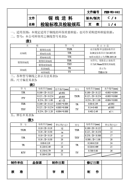
文件编号 FHN-W3-002
圆铜线
软圆铜线 硬圆铜线
三、各种型号铜线之表示方法见表1:
TXJR TJR TJX TXR TXY TR TY
绞合股数/单支线标称直径 如26支标称直径为0.16的裸 铜软绞线表示为:TJR:26/0.16 用型号、规格表示:如标直 径为0.50mm镀锡软圆铜线
表示为: TXR:0.50
四、尺寸偏差见表2:
表2
型号 TJR JTY TXR TXY
标称直径(mm) 允许偏差(mm)
0.100≤D≤0.125 ±0.002
0.125∠D≤0.254 ±0.003
0.254∠D≤1.00
±1%D
0.100≤D≤0.125 -0.003/+0.004
0.125∠D≤0.254 -0.003/+0.006
0.254∠D≤1.20 -0.004/+0.008
√
等
螺旋千分尺( 将线头的1M线剔除后,取1M铜线测量五个点,记录最大值与
7
线径
0.001㎜) 最小值,须在公范围内,(绞合铜线只测5条)
8
重量
电子磅
将电子磅调整归零,拆开铜线防护层,查看铜线实际毛重与标 签上毛重是否一致(只限非绞线产品)
CP线验收规格书
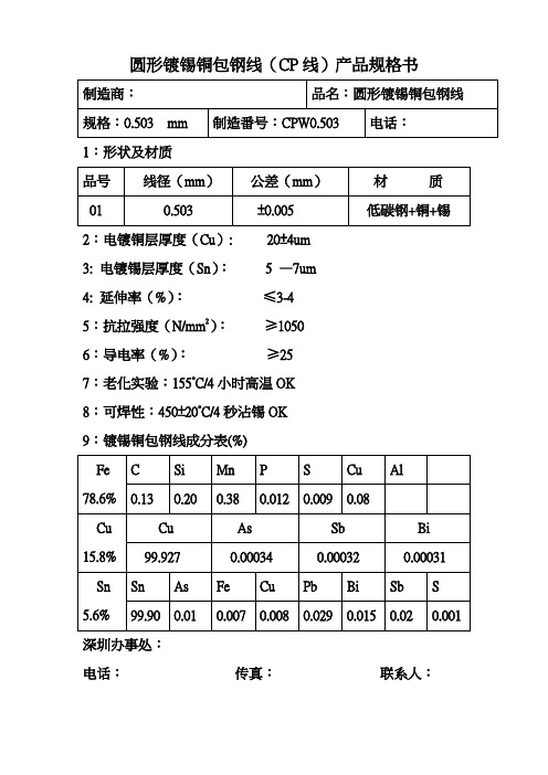
制造商:
品名:圆形镀锡铜包钢线
规格:0.503 mm
制造番号:CPW0.503
电话:
1:形状及材质
品号
线径(mm)
公差(mm)
材 质
01
0.503
±0.005
低碳钢+铜+锡
2:电镀铜层厚度(Cu): 20±4um
3: 电镀锡层厚度(Sn): 5 —7um
4: 延伸率(%):≤3-4
5:抗拉强度(N/mm2):≥1050
6:导电率(%):≥25
7:老化实验:155°C/4小时高温OK
8:可焊性:450±20°C/4秒沾锡OK
9:镀锡铜包钢线成分表(%)
Fe
78.6%
C
Si
Mn
P
S
Cu
Al
0.13
0.20
0.38
0.012
0.009
0.08
Cu
15.8%
Cu
As
Sb
Bi
99.927
电话:
1:形状及材质
品号
线径(mm)
公差(mm)
材 质
01
0.40
±0.005
低碳钢+铜+锡
2:电镀铜层厚度(Cu): 20±4um
3: 电镀锡层厚度(Sn): 5 —7um
4: 延伸率(%):≤3-4
5:抗拉强度(N/mm2):≥1000
6:导电率(%):≥25
7:老化实验:155°C/4小时高温OK
8:可焊性:450±20°C/4秒沾锡OK
9:镀锡铜包钢线成分表(%)
Fe
78.6%
C
B227 硬拉铜包钢线标准规范(中文翻译)

B227-04 硬拉铜包钢线标准规范1、范围1.1此规范包含了电气用的裸硬拉圆铜包钢线(备注1)备注1:此规范订购的线材不适合再拉。
如果需要再拉,请咨询供应商。
1.2 明确了四种等级的线材,具体如下:等级40HS,等级40EHS,等级30HS,等级30EHS。
备注2:此规范包含的等级与以下商业描述一致:等级40HS,高强度,40%传导性等级40EHS,超高强度,40%传导性等级30HS,高强度,30%传导性等级30EHS,超高强度,30%传导性1.3 用单位英寸-磅表示的值被视为是标准,圆括号中给出的值是用SI单位。
2、参考文件2.1 以下在采购时即生效的文件作为此规范的一部分供参考:2.2ASTM标准B193电子导体材料的电阻测试方法B258用于电子导体的单支圆铜线AWG尺寸的标称线径和截面积规范2.3 国际标准和技术研究所NBS 手册100——铜线表3、订单信息3.1 此规范下的材料订单应包含以下信息:3.1.1 每种尺寸和等级的数量3.1.2 线材尺寸:线径用英寸表示(参考5.1 和表1)3.1.3 等级(参考1.2和表1)3.1.4 测量伸长率方法(参考7.3和7.4)3.1.5 包装尺寸(参考14.1)3.1.6 特殊包装唛头,如果需要(第13部分)3.1.7 检测地点(第15部分)4、材料4.1 线材应由一根钢芯,同时一个均匀连续的铜紧紧包覆在钢上组成。
4.2 成品铜包钢线应符合此规范描述的要求。
5、尺寸和可允许变差5.1 尺寸用线径表示,单位为英寸,同时保留4位小数备注3:表1中线径的值精确到0.0001英寸,与规范B258中给出的标准尺寸一致。
在明确或检测线径时,用四位小数表示。
星号前的线径不在美国线规中,也是用四位小数表示的。
他们与英国标准线规的伯明翰线径规一致,被用于通信线。
明确线材尺寸的量具数量的使用未在此规范中说明,因为可能会引起争论。
NBS手册100中有更多的讨论。
5.2 表1中包括的线径范围内,线径不能超出规定线径的以下值:精确到0.1英里(0.0001英寸)规定的线径允许的变差英寸(mm)0.2043(5.189)至0.1000(2.540),包括+/-1.5%0.0999(2.537)至 0.0800(2.032),包括+/-0.0015英寸(1.5英里)(0.038mm)0.0799(2.029)至0.0600(1.524),包括+0.0010英寸(1.0英里)(0.025mm)-0.0015英寸(1.5英里)(0.038mm)0.0599(2.029)和以下值+/-0.0010英寸(1.0英里)(0.025mm)5.3任一批线材的十分之一,但是不少于五轴(或所有,如果一批少于5轴),应在3处测量。
镀锡铜包线标准

镀锡铜包钢线的镀层厚度应符合表2的要求,也可根据客户要求生产线径和线径偏差.表2单位:um剥锡前线径—剥锡后线径镀层厚度= 2镀锡铜包钢线表面应光洁,色泽均匀,不应有露铜、脱锡、黑斑、锈蚀、裂纹、伤痕和超过允许偏差的锡瘤、毛刺等缺陷.镀锡铜包钢线在温度20℃时,根据客户的要求,导电率28%-30%之间,供客户选择。
镀锡铜包钢线的机械性能应符合表3的要求.表3镀锡铜包钢线应具有良好的可焊性,经加速老化后,焊接时间不大于2S或润湿力<φmN,镀锡铜包钢线应具有良好的抗老化性.纯锡层铜线在200±5℃烘烤1小时或175±5℃烘烤4小时后,无发黄发黑.老化后可焊性合格.5.试验方法按条要求,镀锡铜包钢线的直径用分度值为0.01mm 千分尺在经过外观检验的样本上,距试样两端10mm 及试样的中央部位,分别在同一截面的两个相互垂直的方向上测量,取其平均值.按条要求,镀锡铜包钢线的表面用肉眼,在规定抽取的每轴(桶)样本单位长度上进行全面检验.按条要求,镀锡铜包钢线的镀层厚度采用剥锡液铜线表面镀层去掉,取试样10-20cm浸入溶液中2-5分种,看到锡层完全去掉,露出原铜包钢线,拿出来用水冲洗干净,擦干后,用千分尺测量未去镀层和已去镀层的铜包钢线,互相垂直各测量二次,测两个部位取其平均值.按条求,镀锡铜包线电阻率试验方法:在规定抽取经线外观检验的每轴(桶)样本上,用双臂电桥或其他能准确测量的设备进行测量,取三个试样的计算平均值.原铜包钢线和锡锭供应商固定不变时,允许电阻率每半年检查一次.5.5.1抗拉强度将试样固定在拉力计的试验架上,开启拉力开关,至试样拉断,读出拉力计读数F,抗拉强度σb=4F/IId2,,其中F(拉断时拉力):N,d(直径):mm.5.5.2 延伸率将试样固定在延伸测试装置上,启动延伸率拉伸开关,至拉断,直接读出延伸率读数,也可按下列方式计算:延伸率=[(后标尺长度—原标尺长度)/原标尺长度]×100%5.5.3 反复弯折(客户无要求可不做此项)反复弯折试验是沿着试样的轴向,施加表3规定的负荷,在曲率半径mm的专用夹具上进行,以弯曲至90度,然后复原,朝相反方向弯曲至90度,再复原作为一个循环.以适当的速度反复弯曲,直至折断,取三个试样折断时的最小循环次数为弯折次数.按条要求镀锡铜包钢线的可焊性试验方法5.6.1试样的制备在按规定数量抽取的每轴(桶)样本单位上,以外观检验后,截取试样100mm长,试样不应被手指接触或受到其它污染,进行可焊性试验前,试样不进行清洁处理. 5.6.2 试验方法5.6.2.1 在焊锡性试验仪上,将温度调至250±5℃,待温度平衡后,将试样浸入无铅的锡焊料中浸2秒,迅速平稳提起,试样表面应被焊料覆盖,无肉眼可风的未覆盖处,表面光洁,无锡环、锡瘤.5.6.2.2将试样在可焊性测试仪上进行测量(具体操作见可焊性测试仪操作指导书).试验结果,润湿力<φMN为合格.将镀锡铜包钢线试样置于200±5℃的烘烤箱内烘烤1小时或175±5℃的烘箱内烘烤4小时后(烘箱内应通风),规格分别为H-2、H-3的镀锡的铜包钢线,应无明显的发黄或变黑,规格分别为H-0、H-1的镀锡铜线无此项要求。
铜包钢

铜包钢线是发钢丝为芯,外覆铜层的双金属导线,高频电阻小,强度较大。主要用于架空通信线路,也可用于大跨越或其他腐蚀严重地区的电力线路上。
1型号、规格、线径编差、直流电阻见表1
2.主要技术指标
A:铜层厚度、抗拉强度及弯曲次数见表2
B:扭转试验铜包钢线经受定向扭转7次左右,不得出现折边及夹杂物,试件长度见见表3的规定。
8
6.00
0.23
637
6
表3
铜包钢线扭转试验的长度
标称线径mm
试验长度(mm)
1.20-Байду номын сангаас.00
200
5.00-6.00
300
±0.05
2.00
表2
铜包钢线的铜层厚度、抗拉强度及弯曲次数
标称线径mm
铜层厚度mm
≥
抗拉强度
MPa
弯曲次数
1.20
0.06
735
15
1.60
0.08
735
12
2.00
0.10
735
10
2.20
0.11
735
9
2.50
0.12
735
8
2.80
0.14
735
8
3.00
0.15
735
8
4.00
0.21
735
表1
型号、规格、线径编差、直流电阻
型号
标称线径mm
线径偏差
直流电阻(20℃)
GT
1.20
±0.04
47.30
1.60
±0.04
26.00
2.00
±0.04
ASTM B452-2002 铜包钢线标准规范(英文)
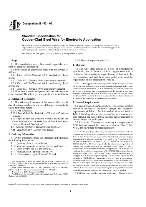
Designation:B452–02Standard Specification forCopper-Clad Steel Wire for Electronic Application1This standard is issued under thefixed designation B452;the number immediately following the designation indicates the year of original adoption or,in the case of revision,the year of last revision.A number in parentheses indicates the year of last reapproval.A superscript epsilon(e)indicates an editorial change since the last revision or reapproval.This standard has been approved for use by agencies of the Department of Defense.1.Scope1.1This specification covers bare round copper-clad steel wire for electronic application.1.2Four classes of copper-clad steel wire are covered as follows:1.2.1Class30HS—Nominal30%conductivity hard-drawn,1.2.2Class30A—Nominal30%conductivity annealed, 1.2.3Class40HS—Nominal40%conductivity hard-drawn,and1.2.4Class40A—Nominal40%conductivity annealed. 1.3The values stated in inch-pound units are to be regarded as the standard.The values given in parentheses are in SI units.2.Referenced Documents2.1The following documents of the issue in effect on the date of material purchase form a part of this specification to the extent referenced herein:2.2ASTM Standards:B193Test Method for Resistivity of Electrical Conductor Materials2B258Specification for Standard Nominal Diameters and Cross-Sectional Areas of AWG Sizes of Solid Round Wires Used as Electrical Conductors22.3National Institute of Standards and Technology: NBS Handbook100—Copper Wire Tables33.Ordering Information3.1Orders for material under this specification shall include the following information:3.1.1Quantity of each size and class,3.1.2Wire size,diameter in inches(see5.3and Table1), 3.1.3Class of wire(see1.2and Table1),3.1.4Packaging and shipping(Section10),3.1.5If inspection is required(see6.3.3),and3.1.6Place of inspection(see6.1).4.Material4.1The wire shall consist of a core of homogeneous open-hearth,electric-furnace,or basic-oxygen steel with a continuous outer cladding of copper thoroughly bonded to the core throughout and shall be of such quality as to meet the requirements of this specification(Note1).N OTE1—The copper-clad steel wire provides a high-strength conductor for use in wire and cable where greater strength is required and a lower conductivity can be tolerated.At high frequencies the reduced conductiv-ity is less pronounced due to concentration of the current in the outer periphery of the wire.Minimum thickness of6%and10%of the radius for30and40%conductivity material,respectively,has been established to facilitate the inspection of thickness onfine wires.5.General Requirements5.1Tensile Strength and Elongation—The copper-clad steel wire shall conform to the tensile strength and elongation requirements of Table1.For intermediate sizes not listed in Table1,the elongation requirements of the next smaller size shall apply;in the case of tensile strength,the requirements of the next larger size shall apply.5.2Resistivity—The electrical resistivity at a temperature of 20°C shall not exceed the values prescribed in Table2.See Note2for calculating electrical resistance.N OTE2—Relationships which may be useful in connection with the values of electrical resistivity prescribed in this specification are shown in Table3.Resistivity units are based on the International Annealed Copper Standard(IACS)adopted by IEC in1913,which is1⁄58V·mm2/m at20°C for100%conductivity.The value of0.017241V·mm2/m and the value of 0.15328V·g/m2at20°C are respectively the international equivalent of volume and weight resistivity of annealed copper equal to100% conductivity.The latter term means that a copper wire1in.in length and weighing1g would have a resistance of0.15328V.This is equivalent to a resistivity value of875.20V·lb/mile2,which signifies the resistance of a copper wire1mile in length weighing1lb.It is also equivalent,for example,to1.7241µV/cm of length of a copper bar1cm2in cross section.A complete discussion of this subject is contained in NBS Handbook100. The use offive significantfigures in expressing resistivity does not imply the need for greater accuracy of measurement than that specified in Test Method B193.The use offive significantfigures is required for complete reversible conversion from one set of resistivity units to another.5.3Dimensions and Permissible Variations—The wire sizes1This specification is under the jurisdiction of ASTM Committee B01onElectrical Conductors and is the direct responsibility of Subcommittee B01.06onComposite Conductors.Current edition approved April10,2002.Published April2002.Originallypublished as B452–st previous edition B452–93(1998)e1.2Annual Book of ASTM Standards,V ol02.03.3Available from the National Institute of Standards and Technology(NIST),Gaithersburg,MD20899.Copyright©ASTM International,100Barr Harbor Drive,PO Box C700,West Conshohocken,PA19428-2959,United States.shall be expressed as the diameter of the wire in decimal fractions of an inch to the nearest0.0001in.(0.003mm)(Note 3).For diameters under0.0100in.(0.254mm),the wire shall not vary from the specified diameter by more than60.0001in.(0.003mm)and for diameters of0.0100in.(0.254mm)and over,the wire shall not vary from the specified diameter by more than61%,expressed to the nearest0.0001in.(0.003 mm).N OTE3—The values of the wire diameters in Table1are given to the nearest0.0001in.(0.003mm)and correspond to the standard sizes given in Specification B258.The use of gage numbers to specify wire sizes is not recognized in this specification because of the possibility of confusion. An excellent discussion of wire gages and related subjects is contained in NBS Handbook100.5.4Adhesion and Other Defects—The copper-clad steel wire,when tested in accordance with7.4,shall not reveal any seams,pits,slivers,or other imperfection of sufficient magni-tude to indicate inherent defects or imperfections.Examination of the wire at the break with the unaided eye(normal spectacles excepted)shall show no separation of copper from the steel.5.5Joints—Necessary joints in the wire and rods prior to final drawing shall be made in accordance with good commer-cial practice.Thefinished wire shall contain no joints or splices made atfinished size.5.6Finish—The wire shall be free from copper discontinui-ties and all imperfections not consistent with good commercial practice(see7.5).5.7Copper Thickness—The minimum copper thickness due to eccentricity shall be not less than the following:5.7.1The30%conductivity wire shall have a minimum thickness of not less than6%of the wire radius.5.7.2The40%conductivity wire shall have a minimum thickness of not less than10%of the wire radius(see7.6and Note3).6.Inspection6.1General—All tests and inspections shall be made at the place of manufacture unless otherwise agreed upon between the manufacturer and the purchaser at the time of the purchase. The manufacturer shall afford the inspector representing the purchaser all reasonable facilities to satisfy him that theTABLE1Tensile and Elongation RequirementsDiameter Cross-Sectional Area at20°C Tensile Strength,psi(kgf/mm2)Elongation,min.%in10in.(250mm)in.mm cmil in.2mm2Class30HS,min Class30A,min Class40HS,min Class40A,minClass30HS and40HSClass30A and40A0.0720 1.8351800.00407 2.63127000(89.3)50000(35.2)110000(77.3)45000(31.6) 1.515 0.0641 1.6341100.00323 2.08127000(89.3)50000(35.2)110000(77.3)45000(31.6) 1.515 0.0571 1.4532600.00256 1.65127000(89.3)50000(35.2)110000(77.3)45000(31.6) 1.515 0.0508 1.2925800.00203 1.31127000(89.3)50000(35.2)110000(77.3)45000(31.6) 1.5150.0453 1.1520500.00161 1.04127000(89.3)50000(35.2)110000(77.3)45000(31.6) 1.515 0.0403 1.0216200.001280.823127000(89.3)50000(35.2)110000(77.3)45000(31.6) 1.015 0.03590.91212900.001010.653127000(89.3)50000(35.2)110000(77.3)45000(31.6) 1.015 0.03200.81310200.0008040.519127000(89.3)50000(35.2)110000(77.3)45000(31.6) 1.0150.02850.7248120.0006380.412127000(89.3)55000(38.7)110000(77.3)50000(35.2) 1.015 0.02530.6436400.0005030.324127000(89.3)55000(38.7)110000(77.3)50000(35.2) 1.015 0.02260.5745110.0004010.259127000(89.3)55000(38.7)110000(77.3)50000(35.2) 1.015 0.02010.5114040.003170.205127000(89.3)55000(38.7)110000(77.3)50000(35.2) 1.010 0.01790.4553200.0002520.162127000(89.3)55000(38.7)110000(77.3)50000(35.2) 1.010 0.01590.4042530.0001990.128127000(89.3)55000(38.7)110000(77.3)50000(35.2) 1.010 0.01420.3612020.0001580.102127000(89.3)55000(38.7)110000(77.3)50000(35.2) 1.010 0.01260.3201590.0001250.0804127000(89.3)55000(38.7)110000(77.3)50000(35.2) 1.0100.01130.2871280.0001000.0647127000(89.3)55000(38.7)110000(77.3)50000(35.2) 1.010 0.01000.2541000.00007850.0507127000(89.3)55000(38.7)110000(77.3)50000(35.2) 1.010 0.00890.22679.20.00006220.0401127000(89.3)55000(38.7)110000(77.3)50000(35.2) 1.010 0.00800.20364.00.00005030.0324127000(89.3)55000(38.7)110000(77.3)50000(35.2) 1.010 0.00710.18050.40.00003960.025*******(89.3)55000(38.7)110000(77.3)50000(35.2) 1.010 0.00630.16039.70.00003120.020*******(89.3)55000(38.7)110000(77.3)50000(35.2) 1.010 0.00560.14231.40.00002460.0159127000(89.3)55000(38.7)110000(77.3)50000(35.2) 1.010 0.00500.12725.00.00001960.0127127000(89.3)55000(38.7)110000(77.3)50000(35.2) 1.0100.00450.11420.20.00001590.010*******(89.3)55000(38.7)110000(77.3)50000(35.2) 1.010 0.00400.10216.00.00001260.00811127000(89.3)55000(38.7)110000(77.3)50000(35.2) 1.010 0.00350.08912.20.000009620.00621127000(89.3)55000(38.7)110000(77.3)50000(35.2) 1.010 0.00310.0799.610.000007550.00487127000(89.3)55000(38.7)110000(77.3)50000(35.2) 1.010TABLE2Resistivity,max,at20°CClass of Wire V·mm2/m30HS and30A 40HS and40A 0.05862(0.058616) 0.04397(0.043970)material is being furnished in accordance with this specifica-tion(Note4).N OTE4—Cumulative results secured on the product of a single manu-facturer,indicating continued conformance to the criteria,are necessary to ensure an overall product meeting the requirements of this specification. The sample sizes and conformance criteria given for the various charac-teristics are applicable only to lots produced under these conditions. 6.1.1Unless otherwise agreed by the manufacturer and the purchaser,conformance of the wire to the various requirements listed in Section5shall be determined on samples taken from each lot of wire presented for acceptance.6.1.2The manufacturer shall,if requested prior to inspec-tion,certify that all wire in the lot was made under such conditions that the product as a whole conforms to the requirements of this specification as determined by regularly made and recorded tests.6.2Definitions:6.2.1lot—any amount of wire of one class and size pre-sented for acceptance at one time,such amount,however,not to exceed10000lb(4500kg)(Note5).N OTE5—A lot should comprise material taken from a product regularly meeting the requirements of this specification.Inspection of individual lots of less than500lb(230kg)of wire cannot be justified economically. For small lots of500lb(230kg)or less,the purchaser may agree to the manufacturer’s regular inspection of the product as a whole as evidence of acceptability of such small lots.6.2.2sample—a quantity of production units(coils,reels, etc.)selected at random from the lot for the purpose of determining conformance of the lot to the requirements of this specification.6.2.3specimen—a length of wire removed for test purposes from any individual production unit of the sample.6.3Sample Size—The number of production units in a sample(see Note4)shall be as follows:6.3.1For tensile strength,elongation,resistivity,and adhe-sion and other defects,the sample shall consist of four production units.For surfacefinish the sampling shall be in accordance with Table4.From each unit,one test specimen of sufficient length shall be removed for the performance of the required tests.6.3.2For dimensional measurements,the sample shall con-sist of a quantity of production units shown in Table5under heading“First Sample.”6.3.3For packaging inspection(when specified by the purchaser at the time of placing the order),the sample shall consist of a quantity of production units as shown in Table4.7.Test Methods7.1Tensile Strength and Elongation—The tensile strength, expressed in pounds per square inch(or kilograms-force per square millimetre),shall be obtained by dividing the maximum load carried by the specimen during the tension test,by the original cross-sectional area of the specimen.Tensile strength and elongation may be determined simultaneously on the same specimen.7.1.1For Classes30A and40A,the elongation of wire may be determined as the permanent increase in length,expressed in percent of the original length,due to the breaking of the wire in tension,measured between gage marks placed originally10 in.(250mm)apart upon the test specimen(Note6).The elongation of wire shall be determined as described above or by measurements made between the jaws of the testing machine.When the latter method is used,the zero length shall be the distance between the jaws at the start of the tension test when10%of the minimum specified breaking load has been applied and be as near10in.(250mm)as practicable,and the final length shall be the distance between the jaws at the time of rupture.The fracture shall be between gage marks in the case of specimens so marked or between the jaws of the testing machine and not closer than1in.(25mm)to either gage mark or either jaw.N OTE6—It is known that the rate of loading during tension testing affects the performance of the sample to a greater or lesser extent depending upon many factors.In general,tested values of tensile strength are increased and tested values of elongation are reduced with increase of speed of the moving head of the testing machine.In the case of tests on soft or annealed wire,however,the effects of speed of testing are not pronounced.Tests of soft wire made at speeds of moving head which under no-load conditions are not greater than12in./min(300mm/min)do not alter thefinal results of tensile strength and elongation determinations to any practical extent.In the case of hard-drawn wire,these effects are pronounced when the speed of the moving head is excessive.It is suggested that tests be made at speeds of moving head which,under no-load conditions,are not greater than3in./min(76mm/min),but in no case at a speed greater than that at which correct readings can be made.7.1.2For Classes30HS and40HS,the elongation shall be measured by means of an extensometer or other device suitable for measuring elongation in10in.(250mm),and having a vernier reading to0.01in.(0.25mm)attached to the test specimen at a tension load of approximately10%of rated strength.The elongation shall be observed while applying a tension load to the specimen and the reading when fracture occurs shall be taken as the elongation of the specimen.TestsTABLE3Equivalent Resistivity ValuesClass Volume Conduc-tivity at20°C,%IACS Resistivity Equivalents at20°CVolume MassV·mm2/m V·cmil/ftµV·in.µV·cm V·lb/mile2V·g/m240A and40HS39.2100.04397026.45 1.7312 4.39702046.30.35836 30A and30HS29.4130.05861635.26 2.3078 5.86162727.80.47772 TABLE4Sampling for Surface Finish and Packaging InspectionNo.of Units in Lot No.of Unitsin Sample,nAllowable No.of Defective Units,c1to30,incl All0 31to50,incl300 51to100,incl370 101to200,incl400 201to300,incl701 301to500,incl1002 501to800,incl1303 Over8001554in which the elongation is less than specified,but in which the fracture has occurred within 1in.(25mm)of the jaws or extensometer clamps,shall be disregarded.7.2Resistivity —The electrical resistivity of the material shall be determined in accordance with Test Method B 193.7.3Dimensional Measurements —Dimensional measure-ments shall be made with a micrometer caliper equipped with a vernier graduated in 0.0001in.(0.0025mm).Each coil shall be gaged at three places,one near each end and one near the middle.From each spool approximately 12ft (3600mm)shall be unreeled and the wire gaged in six places between the second (600th mm)and twelfth foot (3600th mm)from the end.7.4Torsion Test —The wire shall withstand without fracture not less than 20torsions in a length equivalent to 100times the nominal diameter of the specimen.All twists shall be made in the same direction.The rate of applying the twists shall be approximately 15/min.Specimens shall be twisted to destruc-tion and shall meet the requirements of 5.4of this specification.7.5Finish —Surface finish inspection shall be made with the unaided eye (normal spectacles excepted).7.6Copper Thickness —Determination of the minimum copper thickness shall be done by microscopical examination of the polished end or by standard stripping methods or by any other suitable method agreed upon between the manufacturer and the purchaser.8.Conformance Criteria (See Note 4)8.1Any lot of wire,the samples of which comply with the conformance criteria of this section,shall be considered as complying with the requirements of Section 5.Individual production units that fail to meet one or more of the require-ments shall be rejected.Failure of a sample group from a lot to meet one or more of the following criteria shall constitute cause for rejection of the lot.The conformance criteria for each of the prescribed properties given in Section 5are as follows:8.2Tensile Strength and Elongation (for all Classes)—The lot shall be considered conforming,if the values of the four specimens are not less than the appropriate values in Table 1.8.3Resistivity —The electrical resistivity of each of the four specimens shall conform to the requirements of Table 2.Failure to meet these requirements shall constitute failure to meet the resistivity conformance criterion of 5.2.8.4Dimensions —The dimensions of the first sample (Table 4)shall conform to the requirements of 5.3.If there are no failures,the lot shall be considered as conforming to these requirements.If there are failures,but the number of these donot exceed the allowable defect number c 2(Table 5)for the respective number of units in the sample,a second sample equal to n 2shall be taken and the total defects of the n 1+n 2units shall not exceed the allowable defect number c 2.Failure to meet this requirement shall constitute failure to meet the dimensional conformance criterion.8.5Adhesion —Adhesion of the copper cladding to the steel of each of the four specimens shall conform to the require-ments of 5.4.Failure of more than two specimens shall constitute failure to meet the adhesion criterion.If more than two specimens fail to meet the adhesion criterion,four addi-tional specimens from the lot shall be tested,all of which shall conform to the adhesion criterion.However,any individual production unit from which the specimen failed to meet the adhesion criterion shall be rejected.8.6Finish —The finish of the samples taken in accordance with Table 5shall conform to the requirements of 5.6.The number of units in the sample showing surface defects not consistent with commercial practice shall not exceed the allowable defect number c,in Table 5.Failure to meet this requirement shall constitute failure to meet the finish conform-ance criterion.8.7Packaging —Conformance to the packaging require-ments specified by the purchaser shall be determined in accordance with Table 5.The number of units in the sample showing nonconformance to the requirements shall not exceed the allowable defect number c ,in Table 4.Failure to meet this requirement shall constitute failure to meet the packaging conformance criterion.9.Density9.1For the purpose of calculating mass/unit length,cross sections,etc.,the density of the wire shall be taken as shown below at 20°C for the material covered by this specification (Note 7).ProductEnglish Units Metric Units 30%conductivity 0.2944lb/in 38.15g/mm 340%conductivity0.2975lb/in 38.24g/mm 3N OTE 7—The term mass per unit length is used in this standard as being more technically correct.It replaces the term weight.10.Packaging and Shipping10.1The package size shall be agreed upon by the manu-facturer and the purchaser in the placing of individual orders (Note 8).The wire shall be protected against damage in ordinary handling and shipping.N OTE 8—Attention is called to the desirability for agreement betweenTABLE 5Sampling for Dimensional MeasurementsNo.of Units in LotFirst SampleSecond SampleNo.of Units in Sample,n 1Allowable No.of Defects in Sample,c 1No.of Units in Sample,n 2n 1+n 2Allowable No.of Defects in Both Samples,c 21to 14,incl All 0.........15to 50,incl 140.........51to 100,incl 19023421101to 200,incl 24046702201to 400,incl 290761053401to 800,incl 3301121454Over 800341161504the manufacturer and the purchaser on package sizes which will be sufficiently large and yet not so heavy or bulky that the wire may likely be damaged in handling.11.Keywords11.1clad steel electrical conductor;copper electrical conductor—copper-clad steel;copper-clad steel electrical con-ductor;electrical conductor;hard drawn copper-clad steel wire; steel wire—copper-cladASTM International takes no position respecting the validity of any patent rights asserted in connection with any item mentioned in this ers of this standard are expressly advised that determination of the validity of any such patent rights,and the risk of infringement of such rights,are entirely their own responsibility.This standard is subject to revision at any time by the responsible technical committee and must be reviewed everyfive years and if not revised,either reapproved or withdrawn.Your comments are invited either for revision of this standard or for additional standards and should be addressed to ASTM International Headquarters.Your comments will receive careful consideration at a meeting of the responsible technical committee,which you may attend.If you feel that your comments have not received a fair hearing you should make your views known to the ASTM Committee on Standards,at the address shown below.This standard is copyrighted by ASTM International,100Barr Harbor Drive,PO Box C700,West Conshohocken,PA19428-2959, United States.Individual reprints(single or multiple copies)of this standard may be obtained by contacting ASTM at the above address or at610-832-9585(phone),610-832-9555(fax),or service@(e-mail);or through the ASTM website().。
铜包钢检测标准_铜包钢检测报告
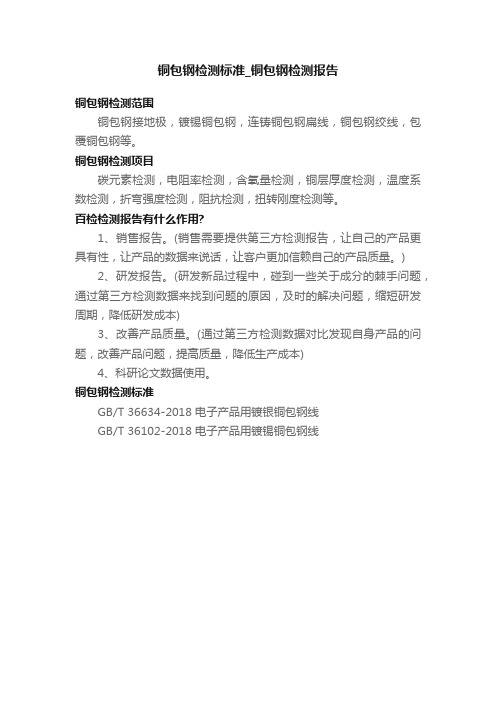
铜包钢检测标准_铜包钢检测报告
铜包钢检测范围
铜包钢接地极,镀锡铜包钢,连铸铜包钢扁线,铜包钢绞线,包覆铜包钢等。
铜包钢检测项目
碳元素检测,电阻率检测,含氧量检测,铜层厚度检测,温度系数检测,折弯强度检测,阻抗检测,扭转刚度检测等。
百检检测报告有什么作用?
1、销售报告。
(销售需要提供第三方检测报告,让自己的产品更具有性,让产品的数据来说话,让客户更加信赖自己的产品质量。
)
2、研发报告。
(研发新品过程中,碰到一些关于成分的棘手问题,通过第三方检测数据来找到问题的原因,及时的解决问题,缩短研发周期,降低研发成本)
3、改善产品质量。
(通过第三方检测数据对比发现自身产品的问题,改善产品问题,提高质量,降低生产成本)
4、科研论文数据使用。
铜包钢检测标准
GB/T 36634-2018 电子产品用镀银铜包钢线
GB/T 36102-2018 电子产品用镀锡铜包钢线。
电线电缆验收要求及相关标准
电线电缆验收要求及相关标准一、电线进场验收标准1。
验收依据:1.1《建筑电气施工质量验收规范》GB50303-2002;1.2《北京市建筑工程资料管理规程》DBJ01-51-2003;2。
产品质量证明文件要求:2。
1电线应有出厂质量证明文件:包括:合格证(合格证有生产许可证编号和“CCC”认证标识)、检测报告、“CCC’认证证书;2。
2电线质量证明文件应为原件,如果是复印件,复印件和原件内容一致,并加盖原件存放单位公章,注明原件存放处,并有经办人签字和时间;2.3生产厂家要有企业法人营业执照。
3.验收标准:3.1电线绝缘皮标识清楚,标识间距不大于1米,要标明生产厂名、规格型号、额定电压和“CCC”认证标识;标识要字迹清晰,用浸有汽油或酒精的棉布以1m/s的速度匀速连续擦拭五次,字迹仍清晰可辩;3.2检测电线线径和绝缘皮厚度(用卡尺或千分尺),参考数据见附表1; 3.3测量线皮绝缘电阻值,将电线浸在水中24小时,用750V绝缘摇表摇测,阻值大于0.5MΩ;3。
4线芯不能松动;3。
5检测电线长度,将电线展开拉直用皮尺量,将实际长度和标识长度对比; 3。
6称重,抽检整盘线的重量,参考数据见附表1。
二、电缆进场验收标准1.验收依据:1.1《建筑电气施工质量验收规范》GB50303-2002;1.2《北京市建筑工程资料管理规程》DBJ01-51-2003;2.产品质量证明文件要求:2.1电缆应有出厂质量证明文件:包括:合格证、厂家检测报告;2。
2电缆质量证明文件应为原件,如果是复印件,复印件和原件内容一致,并加盖原件存放单位公章,注明原件存放处,并有经办人签字和时间;2。
3生产厂家要有企业法人营业执照、生产许可证。
3。
验收标准:3。
1电缆绝缘皮标识清楚,标识间距不大于1米,要标明生产厂名、规格型号和米数;标识要字迹清晰,用浸有汽油或酒精的棉布以1m/s的速度匀速连续擦拭五次,字迹仍清晰可辩;3.2检查线芯股数和单股线芯的直径;3.3预分支电缆验收时要注意分支电缆的长度、分支之间的长度、吊钩到第一个分支的长度及预分支电缆的分支方向(上分支或下分支),且每根预分支电缆均要附图。
电线、电缆现场验收标准
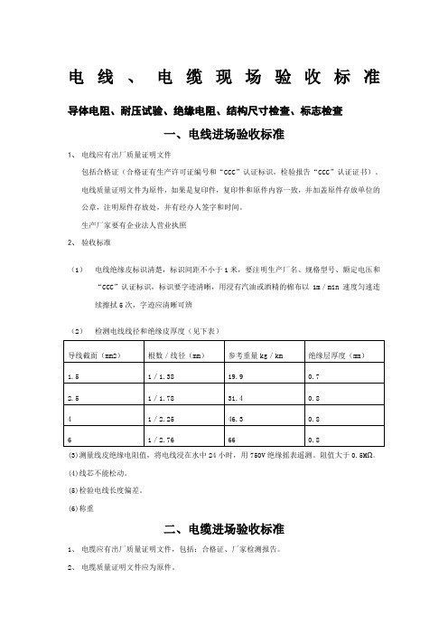
电线、电缆现场验收标准导体电阻、耐压试验、绝缘电阻、结构尺寸检查、标志检查
一、电线进场验收标准
1、电线应有出厂质量证明文件
包括合格证(合格证有生产许可证编号和“CCC”认证标识,检验报告“CCC”认证证书)。
电线质量证明文件为原件,如果是复印件,复印件和原件内容一致,并加盖原件存放单位的公章,注明原件存放处,并有经办人签字和时间。
生产厂家要有企业法人营业执照
2、验收标准
(1)电线绝缘皮标识清楚,标识间距不小于1米,要注明生产厂名、规格型号、额定电压和“CCC”认证标识,标识要字迹清晰,用浸有汽油或酒精的棉布以1m/min速度匀速连续擦拭5次,字迹应清晰可辨
(2)检测电线线径和绝缘皮厚度(见下表)
(3)测量线皮绝缘电阻值,将电线浸在水中24小时,用750V绝缘摇表遥测。
阻值大于0.5MΩ。
(4)线芯不能松动。
(5)检验电线长度偏差。
(6)称重
二、电缆进场验收标准
1、电缆应有出厂质量证明文件,包括:合格证、厂家检测报告。
2、电缆质量证明文件应为原件。
3、电缆绝缘皮标识清楚,标识间距不大于1米,要标明生产厂名、规格型号和米数,标识要字
迹清晰,用浸有汽油或酒精的棉布以1m/s的速度匀速连续擦拭5次,字迹仍清晰可辨。
4、检查线芯的股数和单股线芯的直径(见下表)
5、测量电缆绝缘皮的绝缘电阻值,用1000V绝缘摇表摇测,阻值大于10MΩ。
- 1、下载文档前请自行甄别文档内容的完整性,平台不提供额外的编辑、内容补充、找答案等附加服务。
- 2、"仅部分预览"的文档,不可在线预览部分如存在完整性等问题,可反馈申请退款(可完整预览的文档不适用该条件!)。
- 3、如文档侵犯您的权益,请联系客服反馈,我们会尽快为您处理(人工客服工作时间:9:00-18:30)。
J—0012010-7-9
二、原材料检测项目:
原材料材质:钢材采用上海宝钢生产的优质低碳钢线作为主要材料。
三、成品检测项目: 1、外观:
1.1 无伤痕,表面光滑,色泽均匀。
1.2 无氧化现象。
1.3 种类、规格、标示正确。
1.4 检测方法:目视。
2、成品完成线径:
2.1 标准:线径范围:见附件 2.2 检验仪器:千分尺。
3、伸长率:用校验合格之伸长率试验机对伸长率作检验 3.1 标准::见附件。
3.2 检验仪器:伸长仪。
3.3.2伸长率值为测试样品拉断后试验夹指针所对应之数字或所显示之数值为该样品之3.3.3试验时标点25cmm为试验段,若在25cm两端支点拉断,则测试无效,此时需要重作试 品管课
1 of 3左雄伟
起稿
页数一、适用范围: 铜包钢线
验,直至在中间拉断为有效;
3.3.4伸长率=(拉伸后总长度-原标距)/原标距*100
3.3测试方法:
3.3.1取约40cm长一条线材试料,在其中标点25cm作为试验段;
伸长率
惠州市惠宇电子有限公司样品品质承认书
编号日期
单位
J—0012010-7-9
锡层厚度导电率电阻值伸长率(mm)(%↑)(Ω↓)(%↑)±0.0021514.6310±0.0021512.0910±0.0021510.1612±0.002158.6612±0.002157.4712±0.00215 6.5012±0.00215 5.7212±0.00215 5.0612±0.00215 4.5212±0.00215 4.0512±0.00215 3.6612±0.00215 3.5512±0.00215 3.3212±0.00215 3.0212±0.00215 2.7712±0.00215 2.5412±0.002
15
2.34
12
-0.003-0.003规格0.0030.0030.003正公差(mm)0.003负公差(mm)-0.003-0.003-0.003-0.003-0.0030.210.22(mm)0.100.180.190.150.130.0030.0030.003
-0.003-0.003-0.003
-0.003-0.0030.003-0.003-0.0030.0030.0030.0030.14-0.0030.160.170.003-0.003-0.0030.003附件 铜包钢退火、镀锡线检验标准
0.110.120.003惠州市惠宇电子有限公司页数 3 of 3日期
起稿
左雄伟
编号0.200.2030.0030.0030.003样品品质承认书
单位
品管课
0.230.240.25
J—0012010-7-9
系数系数(dt)(dt)1.0330.9851.0280.9811.0240.9771.0200.9731.0160.9701.0120.9661.0080.9621.0040.9591.0000.9550.9960.9510.9920.9480.989
0.944
5.2测试方法:
6.1 成品包装根据客户要求,每轴成品必须使用PE膜。
6.2 每轴成品上必须附标签,标签上注明品名规格,制造日期,净重,作业者。
(dt)(t)℃(t)℃0 1.0851224(t)℃ 6、包装:
6.3 检查方法:目视。
11 1.037
23
5. 电阻值:
取约1m 之线材为试料,并加以整直,将样品线两夹入电阻电桥测试仪红黑两夹,读取 电阻值.5.1标准:见附件35
10 1.04122349 1.04521338 1.05020327 1.05419316 1.05818305 1.06317294 1.06716283 1.07215272 1.07614261 1.0811325温度系数温度温度日期
起稿
左雄伟
编号页数 2 of 3惠州市惠宇电子有限公司导电率(%)=样品品质承认书4.导电率
4.2测试方法:
电阻值,从温度系数表中查出对应的温度系数(见下表),求其导电率;4.3计算方法:
单位
品管课
取约1m之线材为试料,并加以整直,将样品线两夹入电阻电桥测试仪红黑两夹,读取4.4温度系数见下表4.1标准:见附件线径*线径*3.14/4*电阻值/温度系数
1.7241
(1.7241为常数)。