上海飞奥 TGM系列%20气体涡轮流量计[1]
上海飞奥燃气调压站

正常供气时常用支路工作(主路),备用支 路进出口阀门开启,切断阀开启,调压器处 于关闭状态。
当主路调压器出现故障造成出口压力超过切 断压力时,主路切断阀将主路切断。管路压 力下降,当压力降至备用支路调压器器启动 压力时,备用支路自动启动,保障正常供气。
为了进一步说明,下面举一个栗子 本站各压力设定值如下: 主路调压器出口压力设定为 3.5MPa, 备用支路调压器出口压力设定为 3.4MPa 主路切断阀切断压力设定在 3.9MPa 备用支路切断阀切断压力设定在 4.0MPa 安全阀启跳压力为进口6.0MPa,出口6.4MPa
正常供气时主路工作,保持 的压力供气,当 主路调压器出现故障,造成出口压力逐渐升 高,压力升至 3.9MPa时,则主路切断阀自动 切断,此时两路均处于关闭状态,由于下游 继续用气,出口管路的压力将逐渐下降,当 压力降至3.4MPa时,备用支路自动启动,保 持出口3.4MPa的压力继续供气。此工艺不但 能保证燃气调压管线超压切断和自动切换, 而且在下游超大气量用气,常用支路的输出 气量不能满足需要,出口压力降至3.4MPa时, 备用支路也能自动启动,此时两路同时供气, 以保证用气需求。
上海飞奥燃气调压站 RX12000简介
RX系列燃气调压站 RX型燃气箱式调压站集燃气过滤,调压,计量及相关电子设 备于一体。具有高精度,高可靠性,占地面积小,安装维护 方便,可靠性高等特点。 RX型燃气箱式调压站有“2+1” 型(2路调压通路+1路旁 通)、“2+0”型(2路调压通路)、“1+1” 型(2路调压通 路+1路旁通)三种结构。 RX型燃气箱式调压站的进口处由绝缘接头、进口压力表和调 试球阀等组成;每个调压通路均由进口截断阀(、过滤器、 调压器(内装式紧急切断阀)、出口压力表、调试球阀和出 口截断阀等组成;手动旁通路由进口截断阀、手动调节阀和 出口针阀等组成;出口处由绝缘接头、安全放散阀和调试球 阀等组成。
Omega FL500系列流量计及开关组合说明书
1®®®®®®®®®®®®®®FL500 SeriesOperator’s ManualIn-Line Flowmeters and Switch Kits2Servicing North America:USA:One Omega Drive, Box 4047ISO 9001 CertifiedStamford, CT 06907-0047Tel: (203) 359-1660FAX: (203) 359-7700e-mail:**************Canada:976 BergarLaval (Quebec) H7L 5A1Tel: (514) 856-6928FAX: (514) 856-6886e-mail:****************For immediate technical or application assistance:USA and Canada:Sales Service: 1-800-826-6342 / 1-800-TC-OMEGA SMCustomer Service: 1-800-622-2378 / 1-800-622-BEST SMEngineering Service: 1-800-872-9436 / 1-800-USA-WHEN SM TELEX: 996404 EASYLINK: 62968934 CABLE: OMEGA Mexico and Latin America:Tel: (95) 800-TC-OMEGA SM FAX: (95) 203-359-7807En Espan ˜ol: (203) 359-1660 ext: 2203e-mail:*****************Servicing Europe:Benelux:Postbus 8034, 1180 LA Amstelveen, The Netherlands Tel: (31) 20 6418405FAX: (31) 20 6434643Toll Free in Benelux: 06 0993344e-mail:************Czech Republic:Ostravska 767, 733 01 Karvina Tel: 42 (69) 6311899FAX: 42 (69) 6311114e-mail:***************France:9, rue Denis Papin, 78190 Trappes Tel: 33 0130-621-400FAX: 33 0130-699-120Toll Free in France: 05-4-06342e-mail:****************Germany/Austria:Daimlerstrasse 26, D-75392 Deckenpfronn, GermanyTel: 49 (07056) 3017FAX: 49 (07056) 8540Toll Free in Germany: 0130 11 21 66e-mail:*****************United Kingdom:25 Swannington Road,P.O. Box 7, Omega Drive,ISO 9002 CertifiedBroughton Astley, Leicestershire,Irlam, Manchester,LE9 6TU, England M44 5EX, England Tel: 44 (1455) 285520Tel: 44 (161) 777-6611FAX: 44 (1455) 283912FAX: 44 (161) 777-6622Toll Free in England: 0800-488-488e-mail:************OMEGAnet SMOn-Line Service Internet e-mail http://***************************It is the policy of OMEGA to comply with all worldwide safety and EMC/EMI regulations thatapply. OMEGA is constantly pursuing certification of its products to the European New Approach Directives. OMEGA will add the CE mark to every appropriate device upon certification.The information contained in this document is believed to be correct but OMEGA Engineering, Inc. accepts no liability for any errors it contains, and reserves the right to alter specifications without notice.WARNING: These products are not designed for use in, and should not be used for, patient connected applications.InstallationInlet and outlet ends are marked on the flow meter body,and an arrow on the printed scale indicates flow direction.Insite flow meters can be mounted in any convenient orientation (vertical, horizontal or anything in-between)without affecting performance. The end fittings are con-nected to the plastic body with O-ring sealed straight threads and don't need to be highly torqued to prevent leakage. These fittings accept pipe with tapered threads (NPT). Teflon tape should be used on the pipe threads and standard torques applied, to make leak-free connections.Put your wrench only on the end fitting when piping on.Do not apply wrenches on the plastic body alone when connecting to pipe.Many users find that a disconnect fitting, installed upstream of the flow meter, makes for easier removal of the flow meter, for cleaning internals. Control valves should be installed downstream of the flow meters.Two scales are provided. One for liquid and one for air/nitrogen gasses. Air/nitrogen gas meters are calibrated in SCFM. The air/nitrogen scale is calibrated at 90 PSI pressure and 70o F temperature. If the flow meter is used with air at pressures and/or temperatures that differ from the above, correction factors can be applied to a 90-psi air scale readings to get correct SCFM values. See Tables.High pressure air vented to atmosphere through the Insiteflow meter may result in erratic readings. When used to4For Electric Signallingmeter. As the magnet moves with the piston, its field trips the proximity switch. An adjustment screw changes the actuation point by moving the switch.8 Watts @ 120 VAC/100 VDC. DO NOT EXCEED 300 MILLIAMPS BELOW 26 VAC/26VDC. Switch has three wires: Black for normally open, blue for normally closed, and white for common.NOTE: Switch has a 25% of full scale operating band. Within the band, the switch activates. Above and below the band, the switch deactivates. Thus,one switch can be used as a deviation alarm.Model FL-505, FL-510, and FL-515 flow meters can be equipped with one or two electric switches so that any flowrate within the range of the meter can be made totrigger a signal (or signals).Switch settings are easily adjusted. They are supplied in kit form for installation in the field.Order No. FL-500-R I .Model FL-530, FL-540 and FL-550 require switch kit #FL-500-R2.Each switch kit consists of a ring shaped ceramicmagnet that fits around the flow meter piston, and aproximity switch in a housing that clamps to the body of the flowStep 1. Install the magnet. You must disassemble the flow meter to do this. Follow instructions found under theheading “Maintenance” on page 3. Remove piston from the shaft and place the magnet between piston and spring.Be sure that the piston is installed as in the drawing,and the spring is seated on the magnet and piston.Insert into tube and replace outlet end fittings.Step 2. Install the foam gasket. It has an adhesive on one side, covered with a protective paper. Peel off and press the gasket firmly into place on the switch housing.Step 3. Install the switch housing on the flow meter body.(A) If you are installing only one switch, push thecapscrews through the switch housing tabs, and thread them into the half-collars, as shown. Use the washers provided. The nuts may be discarded.(B) If you are installing two switches, match up the tabs on the two switch housings and push the capscrews through both collar tabs. Put the nuts on the threaded ends of the capscrews and tighten. Use the washers provided. (The half-collars and extra magnet may be discarded.)SWITCH INSTALLATIONNOTE: There is no “wrong orientation” of the switchhousing. If you are installing two switch housings, they can both be oriented the same way, as in the photo, or one “up”and the other “down”. Install to suit your needs in wiring and switch adjustment.SETTING THE SWITCH POINTSWith flow meter installed:Simply adjust the amount of flow to move the piston to the level on the indicator where a switch signal is desired, then turn the switch adjustment screw until switch actuates.(Switch moves toward the adjustment screw head as you turn it clockwise. Use an ohmmeter to determine actua-tion.) Repeat for second switch, if you are using two switches.With flow meter NOT installed:Simulate flow by pushing the eraser-end of a pencil (or a similar tool) through the inlet end of the tube, contacting the float, and moving it against the spring pressure until the knife edge of the float is at the desired reading on the scale. (If your unit has a 1/2 in. pipe fitting, remove it to gain better access.) Then, turn the switch adjustment screw till the switch actuates. (Switch moves toward the adjustment screw head as you turn it clockwise. Use an ohmmeter to determine actuation.) Repeat for a second switch, if you are using two switches.When connecting the switch wires, leave enough lead length (as a pigtail) to allow full travel of the switch.5Direct all warranty and repair requests/inquiries to the OMEGA Customer Service Department. BEFORE RETURNING ANY PRODUCT(S) TO OMEGA, PURCHAS ER MUS T OBTAIN AN AUTHORIZED RETURN (AR) NUMBER FROM OMEGA’S CUS TOMER S ERVICE DEPARTMENT (IN ORDER TO AVOID PROCESSING DELAYS). The assigned AR number should then be marked on the outside of the return package and on any correspondence.The purchaser is responsible for shipping charges, freight, insurance and proper packaging to prevent breakage in transit.FOR WARRANTY RETURNS, please have the following information available BEFORE contacting OMEGA:1.P.O. number under which the product wasPURCHASED,2.Model and serial number of the product underwarranty, and3.Repair instructions and/or specific problemsrelative to the product.FOR NON-WARRANTY REPAIRS,consult OMEGA for current repair charges. Have the following information available BEFORE contacting OMEGA: 1. P.O. number to cover the COSTof the repair,2.Model and serial number of product, and3.Repair instructions and/or specific problemsrelative to the product.OMEGA’s policy is to make running changes, not model changes, whenever an improvement is possible. This affords our customers the latest in technology and engineering.OMEGA is a registered trademark of OMEGA ENGINEERING, INC.© Copyright 1996 OMEGA ENGINEERING, INC. All rights reserved. This document may not be copied, photocopied, reproduced, translated, or reduced to any electronic medium or machine-readable form, in whole or in part, without prior written consent of OMEGA ENGINEERING, INC.67M2473/0796Where Do I Find Everything I Need for Process Measurement and Control?OMEGA…Of Course!TEMPERATUREⅪߜThermocouple, RTD & Thermistor Probes, Connectors, Panels & AssembliesⅪߜWire: Thermocouple, RTD & Thermistor ⅪߜCalibrators & Ice Point ReferencesⅪߜRecorders, Controllers & Process Monitors ⅪߜInfrared PyrometersPRESSURE, STRAIN AND FORCEⅪߜTransducers & Strain Gauges ⅪߜLoad Cells & Pressure Gauges ⅪߜDisplacement Transducers ⅪߜInstrumentation & AccessoriesFLOW/LEVELⅪߜRotameters, Gas Mass Flowmeters & Flow Computers ⅪߜAir Velocity IndicatorsⅪߜTurbine/Paddlewheel Systems ⅪߜTotalizers & Batch ControllerspH/CONDUCTIVITYⅪߜpH Electrodes, Testers & Accessories ⅪߜBenchtop/Laboratory MetersⅪߜControllers, Calibrators, Simulators & Pumps ⅪߜIndustrial pH & Conductivity Equipment DATA ACQUISITIONⅪߜData Acquisition & Engineering Software ⅪߜCommunications-Based Acquisition Systems ⅪߜPlug-in Cards for Apple, IBM & Compatibles ⅪߜDatalogging SystemsⅪߜRecorders, Printers & Plotters HEATERSⅪߜHeating CableⅪߜCartridge & Strip Heaters ⅪߜImmersion & Band Heaters ⅪߜFlexible Heaters ⅪߜLaboratory HeatersENVIRONMENTALMONITORING AND CONTROLⅪߜMetering & Control Instrumentation ⅪߜRefractometers ⅪߜPumps & TubingⅪߜAir, Soil & Water MonitorsⅪߜIndustrial Water & Wastewater TreatmentⅪߜpH, Conductivity & Dissolved Oxygen InstrumentsMANUAL M-2473/0896FL500MAN 200.1M 10/96 8。
MF5000 系列气体质量流量计 说明书

© 2011 Siargo Ltd.使用说明书(VA.3)SIARGO MEMS FLOW SENSOR PRODUCTS气体质量流量计MF5000系列1注意事项MF 5000系列气体质量流量计目录使用需知注意事项目录一、概述二、产品分类形式及选型说明三、产品结构与工作原理四、技术指标五、安装说明六、功能说明七、检定八、安全、维护及故障排除九、运输及储存十、开箱及检查十一、客户服务及技术支持附录:应用说明112334556778888 2选型方式按照如下规则确定:MF5000系列气体质量流量计是矽翔微机电系统有限公司结合微机电系统(MEMS )流量传感芯片技术和计算机自适应技术历经多年,开发出的智能化全电子式气体质量流量仪表。
主要技术性能处于国际领先水平,具有高灵敏度、高精度、大量程比等特点;针对工业环境,融合了多种抗干扰措施的电磁兼容设计;且具有多种信号输出,能通过通讯接口实现网络管理功能;本产品在性能、安装、维护方面也具有其独特的优越性,可广泛应用于石油、燃气、化工、冶炼、能源等各个领域。
执行标准为:Q/77453766-11-2009。
参照执行标准: ISO14511;GB/T 20727-2006。
00000360号。
采用微机电系统芯片加工技术和大规模集成电路的生产技术及材料生长技术,传感器的尺寸缩小到了微米量级,使该流量计的灵敏度大大提高。
在单个芯片上实现了多传感器集成,使该流量计的量程比(范围度)大大提高。
传感器零点稳定度较之传统的热式质量流量计有极大的改善。
结合二次仪表的微电脑智能技术,使流量计重复性好,实现了计量准确可靠。
技术进步带来的结构简化,使流量计较之传统的机械式仪表,压力损失大幅度减小,极大地降低了能源消耗。
采用LCD 显示瞬时流量和累积流量,清晰直观,读数方便。
产品融合了电磁兼容设计技术,具有更高抗干扰能力。
流量计带有RS485通讯模块,配合上位计算机网络可实现集中管理。
浅谈天然气计量中的二次仪表
浅谈天然气计量中的二次仪表作者:吴静文章来源:网络论文点击数:19 更新时间:2007-7-22 20:01:26一、二次仪表的产生背景及其由来人们对自然界的认识很大程度上取决于检测和仪表。
流量的检测计量一直是工业生产中过程控制的重要组成部分之一,它与国民经济、国防建设、工业生产、科学研究有密切的关系。
特别是在能源高度紧张、工业生产自动化程度愈来愈高的当今世界,世界各国都在加紧开发新能源来代替传统的煤、石油等一次能源。
与此同时,天然气工业得到了蓬勃发展,伴随着天然气在各国一次能源中的比重不断上升,天然气的计量引起了人们的特别关注,在天然气的采集、处理、储存、运输和分配过程中,需要数以百万计的流量计,其中有些流量计涉及到的结算金额数字巨大,对测量准确度和可靠性要求特别高。
天然气的计量关系到每个用气的公司、个人的切身经济利益。
由于天然气是一种可压缩性流体,作为一次检测仪表的流量计本身仅仅能够检测工况下的气体体积量,无法给出统一状态下的气体体积量,给天然气的贸易计量带来很大的不便。
为了更准确的计量,必须有一种可以在线检测气体的温度、压力和流量信号,并进行压缩因子自动修正和流量自动跟踪补偿,将工况体积量转换成标准状态体积量的仪器,在这种背景下就产生了体积修正仪。
二、体积修正仪的主要功能体积修正仪主要用来在线检测气体的温度、压力、流量等信号,并进行压缩因子自动修正和流量自动跟踪补偿,将工况体积量转换成标准状态体积量的仪表[1]。
具体转换原理为:1、在线检测温度、压力信号;2、检测气体成分(或根据实际情况、设定天然气的气体组分),然后通过温度、压力信号、气体成分计算出压缩因子[2];3、接受流量计发出的流量脉冲信号,并根据流量计的出厂校准曲线对流量计的脉冲信号进行自动修正;4、最后通过气体状态方程计算出标准状态下的流量值,并直接显示计算结果进而达到商业计量的需要。
此外,作为一种现场检测仪表,随着自动化水平和现场总线技术的不断提高,要求体积修正仪具有存储、显示、通讯等功能,部分用于贸易结算的体积修正仪还要求具有打印、计算金额等功能。
Omega FPDM流量计用户指南说明书
e-mail:**************For latest product manuals: FPD M 3000 S eries FPDM3200 Series FPDM3300 Series1/2" - 2" Oval Gear Flowmeterwith MechanicalRegisterShop online at ®User’s Guide***********************Servicing North America:U.S.A.:Omega Engineering, Inc., One Omega Drive, P.O. Box 4047S tamford, CT 06907-0047 USAToll-Free: 1-800-826-6342 (USA & Canada only)Customer Service: 1-800-622-2378 (USA & Canada only)Engineering Service: 1-800-872-9436 (USA & Canada only)Tel: (203) 359-1660 Fax: (203) 359-7700e-mail:**************For Other Locations Visit /worldwideThe information contained in this document is believed to be correct, but OMEGA accepts no liability for any errors it contains, and reserves the right to alter specifications without notice.WARNING: These products are not designed for use in, and should not be used for, human applications.Installation………………………………………………………….Pre-installation checks Page 3………………………………………………………….Operating Principle Page 5………………………………………………………….Installation Procedure Page 5 Maintenance Procedure………………………………………………………….Disassembly Page 6………………………………………………………….Reassembly Page 6 Flowmeter Specifications………………………………………………………….Flowmeter Specifications Page 7-8 Service………………………………………………………….Troubleshooting Guide Page 8………………………………………………………….Exploded Diagram Page 9-10………………………………………………………….Wetted Parts Page 11-13 General………………………………………………………….Pressure Drop Graphs Page 14………………………………………………………….Dimensional Diagrams Page 15-18FLUID COMPATABILITYBefore use, confirm the fluid to beused is compatible with the meter. Re-fer to Industry fluid compatibilitycharts or consult your local represen-tative for advice.AIR PURGE / LINE PRESSURETo prevent damage caused by air purge slowly fill the meter with fluid.To reduce pressure build-up turn off theat the end of each day.STRAINERTo prevent damage from dirt or for-eign matter it is recommended that a Y or Basket type mesh strainer be installed as close aspossible to the inlet side of the me-ter.When a strainer is installed it should be regularly inspected and cleaned. Failure to keep the strainer clean will dramatically effect flow me-ter performance.Contact your local representative for ad-vice.PLEASE READ THIS SAFTEY INFORMATION CAREFULLY BEFORE USE.Read and retain this instruction manual to assist you in the operation and maintenance of this product. This Flow Meter has incorporated the oval rotor principal into its design. This has proven to be a reliable and highly accurate method of measuring flow.Exceptional repeatability and high accuracy over a wide range of fluid viscosities and flow rates are features of the oval rotor design. With a low pressure drop and high pressure rating oval rotor flow meters are suitable for both gravity and pump (in line) applications.If you have any problems with the meter, refer to the maintenance and trouble shooting sections of this manual. This manual contains connection and operating instructions for meters with Mechanical Displays If you need further assistance, contact your local representative or distributor for advice.When fluid passes through the meter the rotors turn, as shown in the diagram below.One of the rotors is fitted with a gearing pinion which (through a secondary gearing set) transfers therotation of the rotor to the Mechanical Register.INSTALLATION PROCEDURE1.It is recommended that when setting up pipe workfor meter installations, a bypass line be included in the design. This provides the facility for a meter to be removed for maintenance without interrupt ing production. (see figure above)e thread sealant on all pipe threads.3.For pump applications ensure pipe work andMeter have the appropriate working pressurerating to match the pressure output of the pump.Refer to Meter Specifications section for furtherdetails.direction.4 Install a wire mesh strainer, as close as possibleto the inlet side of the meter.Meter 1/2”- 2” 250 micron / 60 mesh5 Ensure that the meter is installed so that theflow of the liquid is in the direction of the arrows embossed on the meter body. 6.The meter can be installed in any orientation aslong as the meter shafts are in a horizontal plane.(Refer to diagram below for correct installation) The mechanical register can be removed and re orientated to a different plane if required..Note: Incorrect installation can cause premature wear of meter components.7.Do not over tighten meter connections. .8.It is important that after initial installation youfill the line slowly, high speed air purge couldcause damage to the rotors.9.Test the system for leaks.10.Check the strainer for swarf or foreign material,after the first 200 litres check periodically,particularly if the flow rate is noted to bedecreasing.1)Before reassembling check the condition of the rotors (replace if necessary). Note: there is one long and one short shaft. The short shaft is to accommodate the rotor with the gearing pinion fitted2)Replace the rotors onto the shafts at 90 degrees to each other and check their operation by turning either of the rotors.If the rotors are not in mesh correctly or do not move freely, remove one of the rotors and replace correctly at 90 degrees to the other rotor.3)Re-check the operation of the rotors4)Inspect the gears in the meter cap for wear.(Replace if required, refer to exploded diagram)5)Replace the o’ring into groove in the meter cap, if the o’ring has grown or is damaged in any way replace it with a new part.6)Replace the meter cap making sure that the gear on the rotor is meshing correctly with the gear in the meter cap. Insert the cap head s crews and tighten in a diagonal sequence 1, 4, 2, 5, 3, 6.7)Replace the cover plate inspect the o-ring, bevel gear, for wear or damage. (Replace if necessary).Ensure that the fluid supply to the meter is disconnected, and the line pressure is released before disassembly.Refer to the exploded parts diagram and parts list. 1)Remove the four screws located on the face of the register. Then remove the face plate cover including register assembly.2)Remove the four register mounting screws and remove the lower half of the register housing.3)Remove the six cover plate screws and remove the cover plate.4)Remove the six meter cap screws and remove the meter cap.5)Remove rotors.Cat 11. Conforms to Directive 97/23/EC—1. Conforms to Directive 97/23/EC—1. Conforms to Directive 97/23/EC—Cat 1 Troubleshooting GuideSeries FPDM3x04 Parts ListingSeries FPDM3x05 - FPDM3x07 Parts IdentificationK - FEP/PTFE Encapsulated SS - Stainless Steel 316Al - Aluminium AA610CA - CarbonFKM - FluoroelastomerPPS - Polyphenylene Sulphide PVDF - Polyvinylidene Flouride POM - AcetalPTFE - Polytetrafluoroethylene FFKM - Perfluoro ElastomerType M mechanical registerType M mechanical registerType M mechanical registerType M mechanical registerWARRANTY/DISCLAIMEROMEGA ENGINEERING, INC. warrants this unit to be free of defects in materials and workmanship for a period of 13 months from date of purchase. OMEGA’s WARRANTY adds an additional one (1) month grace period to the normal one (1) year product warranty to cover handling and shipping time. This ensures that OMEGA’s customers receive maximum coverage on each product.If the unit malfunctions, it must be returned to the factory for evaluation. OMEGA’s Customer Service Department will issue an Authorized Return (AR) number immediately upon phone or written request. Upon examination by OMEGA, if the unit is found to be defective, it will be repaired or replaced at no charge. OMEGA’s WARRANTY does not apply to defects resulting from any action of the purchaser, including but not limited to mishandling, improper interfacing, operation outside of design limits, improper repair, or unauthorized modification. This WARRANTY is VOID if the unit shows evidence of having been tampered with or shows evidence of having been damaged as a result of excessive corrosion; or current, heat, moisture or vibration; improper specification; misapplication; misuse or other operating conditions outside of OMEGA’s control. Components in which wear is not warranted, include but are not limited to contact points, fuses, and triacs.OMEGA is pleased to offer suggestions on the use of its various products. However, OMEGA neither assumes responsibility for any omissions or errors nor assumes liability for any damages that result from the use of its products in accordance with information provided by OMEGA, either verbal or written. OMEGA warrants only that the parts manufactured by the company will be as specified and free of defects. OMEGA MAKES NO OTHER WARRANTIES OR REPRESENTATIONS OF ANY KIND WHATSOEVER, EXPRESSED OR IMPLIED, EXCEPT THAT OF TITLE, AND ALL IMPLIED W ARRANTIES INCLUDING ANY W ARRANTY OF MERCHANTABILITY AND FITNESS FOR A PARTICULAR PURPOSE ARE HEREBY DISCLAIMED. LIMITATION OF LIABILITY: The remedies of purchaser set forth herein are exclusive, and the total liability of OMEGA with respect to this order, whether based on contract, warranty, negligence, indemnification, strict liability or otherwise, shall not exceed the purchase price of the component upon which liability is based. In no event shall OMEGA be liable for consequential, incidental or special damages.CONDITIONS: Equipment sold by OMEGA is not intended to be used, nor shall it be used: (1) as a “Basic Component” under 10 CFR 21 (NRC), used in or with any nuclear installation or activity; or (2) in medical applications or used on humans. Should any Product(s) be used in or with any nuclear installation or activity, medical application, used on humans, or misused in any way, OMEGA assumes no responsibility as set forth in our basic WARRANTY /DISCLAIMER language, and, additionally, purchaser will indemnify OMEGA and hold OMEGA harmless from any liability or damage whatsoever arising out of the use of the Product(s) in such a manner.OMEGA’s policy is to make running changes, not model changes, whenever an improvement is possible. This affords our customers the latest in technology and engineering.OMEGA is a registered trademark of OMEGA ENGINEERING, INC.© Copyright 2013 OMEGA ENGINEERING, INC. All rights reserved. This document may not be copied, photocopied, reproduced, translated, or reduced to any electronic medium or machine-readable form, in whole or in part, without the prior written consent of OMEGA ENGINEERING, INC.FOR WARRANTY RETURNS, please have the following information available BEFORE contacting OMEGA:1. P urchase Order number under which the product was PURCHASED,2. M odel and serial number of the product under warranty, and3.Repair instructions and/or specific problems relative to the product.FOR NON-WARRANTY REPAIRS, consult OMEGA for current repair charges. Have the followinginformation available BEFORE contacting OMEGA:1.Purchase Order number to cover the COST of the repair,2.Model and serial number of the product, and3.Repair instructions and/or specific problems relative to the product.RETURN REQUESTS/INQUIRIESDirect all warranty and repair requests/inquiries to the OMEGA Customer Service Department. BEFORE RETU RNING ANY PRODU CT(S) TO OMEGA, PU RCHASER MU ST OBTAIN AN AU THORIZED RETU RN (AR) NU MBER FROM OMEGA’S CU STOMER SERVICE DEPARTMENT (IN ORDER TO AVOID PROCESSING DELAYS). The assigned AR number should then be marked on the outside of the return package and on any correspondence.The purchaser is responsible for shipping charges, freight, insurance and proper packaging to prevent breakage in transit.Where Do I Find Everything I Need for Process Measurement and Control?OMEGA…Of Course!Shop online at SMTEMPERATUREM U Thermocouple, RTD & Thermistor Probes, Connectors, Panels & AssembliesM U Wire: Thermocouple, RTD & ThermistorM U Calibrators & Ice Point ReferencesM U Recorders, Controllers & Process MonitorsM U Infrared PyrometersPRESSURE, STRAIN AND FORCEM U Transducers & Strain GagesM U Load Cells & Pressure GagesM U Displacement TransducersM U Instrumentation & AccessoriesFLOW/LEVELM U Rotameters, Gas Mass Flowmeters & Flow ComputersM U Air Velocity IndicatorsM U Turbine/Paddlewheel SystemsM U Totalizers & Batch ControllerspH/CONDUCTIVITYM U pH Electrodes, Testers & AccessoriesM U Benchtop/Laboratory MetersM U Controllers, Calibrators, Simulators & PumpsM U Industrial pH & Conductivity EquipmentDATA ACQUISITIONM U Data Acquisition & Engineering SoftwareM U Communications-Based Acquisition SystemsM U Plug-in Cards for Apple, IBM & CompatiblesM U Data Logging SystemsM U Recorders, Printers & PlottersHEATERSM U Heating CableM U Cartridge & Strip HeatersM U Immersion & Band HeatersM U Flexible HeatersM U Laboratory HeatersENVIRONMENTALMONITORING AND CONTROLM U Metering & Control InstrumentationM U RefractometersM U Pumps & TubingM U Air, Soil & Water MonitorsM U Industrial Water & Wastewater TreatmentM U pH, Conductivity & Dissolved Oxygen InstrumentsM-5424/0714。
Omega FTB3000系列流量计说明书

FTB3000 SeriesPositive Displacement Meters e-mail:**************For latest product manuals:Contents1.Introduction (3)2.Specifications (5)3.Operation (7)3.1Principle (7)3.2Precautions (7)4.Installation (9)5.Maintenance (11)5.1General (11)5.2Trouble Shooting (11)5.3Spare Parts (12)1.IntroductionThe FTB3000 Series of positive displacement meters incorporates smooth oval rotors in their design. The oval rotor principle has proven to be a reliable and highly accurate method of measuring flow. Along with the smooth oval rotors, exceptional repeatability and high accuracy over a wide range of viscosities and flow rates are features of the FTB3000 Series flow meter design.The low pressure drop and high pressure rating means the Omega FTB3000 Series flow meter is suitable for both gravity and pump (in line) applications.Please take a few minutes to read through this manual before installing and operating your meter. If you have any problems with the meter, refer to the maintenance and troubleshooting sections of this manual.If you need further assistance, contact Omega’s customer service department by telephone or fax for advice.2.SpecificationsService Fluids: Clean liquids, max particle size .125" Accuracy: ± 0.25% of reading or better above 100 cstk Repeatability:± 0.05%Flow Range:w/ Mag Coil Pickup 2 to 20 GPMw/ Hall Effect Pickup 0.02 to 20 GPMK-factor: 460 pulses per gallon (approximate)Operating Temperature:w/ Mag Coil Pickup: -268°C to +232°C (-450°F to +450°F)w/ Hall Effect Pickup: -40°C to +150°C (-40°F to +302°F)Operating Pressure: 3000 PSIG standardMinimum Fluid Viscosity: 100 cstkWetted Parts: 316 SS body and gears with peek gear seats Bearings: Shielded, self lubricating 440 SS ball bearings Connections:Flange Option: 1" MNPT STDPickup Coil: Magnetic Type or Hall Effect (6 to 24 vdc power) Calibration: 10-point calibration traceable to NIST @ 100 cstks3.Operation3.1PrincipleThe FTB3000 Series of positive displacement meters use a pair of smooth oval rotors to provide a reliable and highly accurate measurement of flow. The smooth oval rotors displace a precise volume of fluid which is passed through the measurement chamber during each revolution. The smooth oval rotor design along with the viscosity of the fluid provides a complete viscous seal within the measurement chamber.The unique patented design ofOmega’s Oval Gear meterincorporates two smooth ovalrotors 90 degrees out of phase.The phase relationship of therotors is maintained by twooval timing gears which areout of the flow path. The ovaltiming gears have a pitchdiameter equal to the outsidediameter of the smooth oval rotors.The flow through the meter measurement chamber follows the path of least resistance. Therefore no liquid passes through the center cavity between the rotors. The fluid is displaced from the inlet to the outlet via the area between the smooth oval rotors and the inner diameter of the meter housing.3.2Precautions▪Before use, confirm the fluid to be used is compatible with the meter and make certain that the operating conditions conform to the meter specifications.▪To prevent damage to the meter slowly fill the system with fluid (this will prevent damage that may be caused by air purge).▪Keep the flowrate within the meter ratings.▪Remove meter from the piping, replacing with a short pipe, when cleaning the piping system by flushing. Costly damage to the meter may result if the assembly is cleaned by flushing with the meter installed.4.Installation▪Use thread sealant on all pipe threads.▪Install the meter carefully to avoid pipe strains.▪The meter must be installed on the discharge side of the pump.▪In tank-head operation, the head of the fluid must be higher than the pressure loss of the meter.▪The flow direction must conform to the arrow mark on the meter body.▪The meter must be installed in the correct orientation (see figure below).▪Connect appropriate connector from pick-up from DCS or electronics.Pickup ConnectionsStandard MAGHall Effect(Open Collector) Redi-Pulse(Open Collector)A - Signal (+)B - Common (-)A - 8 - 30 Vdc (+)B - Common (-)C - Pulse OutputA - 3.5 - 24 Vdc (+)B - Common (-)C - Pulse Output5.Maintenance5.1GeneralThe Omega FTB3000 Series flowmeters do not require routine maintenance and do not contain any field serviceable or replaceableparts.5.2Trouble ShootingRefer to the following troubleshooting guide for assistance withpossible meter malfunctions:TROUBLE CAUSE REMEDYFluid will not flow through the meter ▪Meter installedwith incorrectorientation.Re-orientate the meter.▪Line to meterblocked.Clear line to meter.▪Insufficientdifferentialpressure.Increase upstreampressure.Reduced flow through the meter ▪Line to meterpartially blocked.Clear line to meter. ▪Insufficientdifferentialpressure.Increase upstreampressure.Meter readings inaccurate ▪Fluid flowrate istoo low.See “Specifications” formin and max flowrates. ▪Fluid viscosity toolow.Check fluidspecifications.▪Air in fluid. Bleed air from system. ▪Meter drag due toincorrectinstallation.Re-adjust meterinstallation.Meter not giving pulse signal ▪Faulty pickupsensor.Replace pickup sensor.Due to the precision alignment of the Omega FTB3000 Series flowmeter internals, field repairs are not recommended. Should the meter require internal repairs, return the meter to the factory.5.3Spare PartsThe following table contains the recommended spare parts for the Omega FTB3000 Series flowmeters:Item No. Qty Part No. Part Description1 1 300-6005 MAG Coil Pickup; PC24-45G1 1 300-6026 Intrinsically Safe MAGPickup; ISM-0011 1 300-6041 MAG Redi-Pulse Pickup;RPM01S1 1 300-6052 Hall Effect Pickup; HE01S NOTE:The meter pickup must be replaced with a pickup of the same type. Refer to the meter model number for the type of pickupbeing used.M3585/0411。
飞奥调压柜参数

1820*1020*2000
50320421007
RX1000B/S
0~1000
HFA2.5D/100+NORVAL/80+DN150
一进一出,进出口下进下出
2220*1220*2080
50420191000
RX1000B/S
0~1000
HFA2.5D/100+NORVAL/80+DN150
600+200
600B+200B
一进两出下进600B前下出100B后下出
1820*1220*1910
50440120008
RX900Z/Z
600+300
600B+300B
一进两出下进600B前下出100B后下出
1820*1220*1910
50440120008
RX1000Z/Z
600+400
600B+400B
51041400200
结构型式为B+B型
RX150B/Z
100+50
100B+50B
一进两出,下进100B后侧出50B前下出
1520*820*1720
51041600200
RX200B/Z
100+100
100B+100B
一进二出,下进中压后侧出低压前下出
1620*920*1730
50240020006
50340060007
RX650Z/Z
600+50
600B+50B
一进两出,下进600B前侧出50B后侧出
1820*1220*1935
50440120010
02-TBQZ系列气体涡轮流量计
TBQZⅡ/TBQZ/TBQ型气体涡轮流量计一、概述TBQZⅡ/TBQZ/TBQ型为不带机械计数器的两大系列气体涡轮流量计,因配置流量积算仪型号不同,分TBQ型气体涡轮流量计和TBQZ型智能气体涡轮流量计。
其工作原理是:当气流进入流量计时,首先经过特殊结构的整流器并加速,在流体的作用下,涡轮克服阻力矩和磨擦力矩开始转动。
当力矩达到平衡时,转速稳定,涡轮的转速与气体流量成正比,并通过旋转的发讯盘上的磁体周期性地改变传感器磁阻,从而传感器输出与流体成正比的脉冲信号。
TBQ型直接显示工况流量和体积总量;TBQZ型和TBQZⅡ型流量计带温度、压力修正功能,将工况流量和体积总量直接转换成标准状态下的流量和总量。
流量计采用功能强大的新型微处理器,运算精确度高,性能可靠,微功耗,内外电源自动切换工作,锂电池供电可使用五年以上。
产品主要性能指标达到国际先进水平,是石油、化工、电力、冶金工业与民用锅炉等燃气计量和城市天然气、燃气调压站计量及燃气贸易计量的理想仪表。
当TBQZⅡ型配置TFC型修正仪时,可实现GPRS 或短程无线数据传输,组网方便。
产品主要性能参数符合GB/T1894-2003/ISO9951:1993标准,产品荣获国家级新产品称号。
产品执行国家检定规程JJG 1037-2008《涡轮流量计检定规程》和企业标准Q/TX11-2008《气体涡轮流量计》。
(照片)TBQ TBQZ TBQZIITBQZII-TFC-B TBQZII-TFC-G二、特点●采用德国进口仪表专用精密轴承,准确度高,稳定性好,范围度宽(20:1)。
●精心设计的流道结构,避免了气流在轴承间的流动,提高了涡轮流量计的介质适应性。
●独特的反推结构和密封结构设计,确保轴承长期可靠运行。
●采用新型检测元件来代替磁敏感线圈,既避免了磁吸力的存在,且提高了检测灵敏度,进一步降低了始动流量,并提高了产品的稳定性和可靠性。
●独立式机芯设计,互换性好、维护方便。
浙江富马仪表 FLWQ 型气体涡轮流量计 说明书
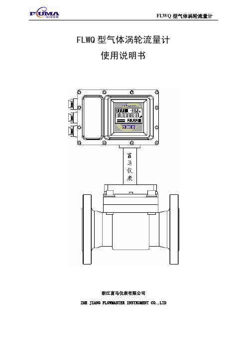
FLWQ型气体涡轮流量计 使用说明书浙江富马仪表有限公司ZHE JIANG FLOWMASTER INSTRUMENT CO.,LTD目 录A 流量计与传感器 (1)1概述 (1)2主要特征 (1)3工作原理 (1)4 产品形式与组成 (2)4.1 组成 (2)4.2 产品形式 (2)4.3 名牌 (3)4.4 安装及外形尺寸 (3)5 技术性能 (4)5.1 执行标准 (4)5.2 精度等级 (4)5.3 性能指标 (4)5.4 电气性能指标 (6)6 安装 (6)6.1 安装要求 (6)6.2 安装中须注意的其他事项 (8)7 流量计的使用 (8)7.1 环境条件 (8)7.2 流体条件 (9)7.3 隔爆型产品使用时应注意 (9)7.4 过范围保护 (9)8 维护 (9)8.1 轴承系统 (9)8.2 安全性和可靠性 (9)8.3 抗干扰能力 (9)9 供应成套性 (10)10 包装、运输及贮存 (10)B 转换器 (11)11 转换器结构 (11)11.1 测量系统 (11)11.2 转换器结构和各部件功能 (11)12 转换器工作原理 (12)13 转换器接线 (13)13.1 接线端子说明见图16和图17 (13)13.2 接线方法(图18) (14)13.3 流量计组网 (14)14 转换器面板形式和按键功能 (15)14.1 正常计量显示的面板 (15)14.2 按键功能 (16)15.3 状态切换见图25 (17)15 用户设置 (17)15.1 用户设置的主要功能 (17)15.2 进入用户设置的方法 (17)16 查阅历史数据 (20)16.1 历史数据查阅的类型 (20)16.2 进入数据查阅的方法 (20)16.3 数据查阅的界面说明见表9 (20)17障现象及其排除方法(见表10) (21)FLWQ型气体涡轮流量计使用说明书A 流量计与传感器1概述FLWQ型气体涡轮流量计是一种精确测量气体流量的速度式流量仪表。
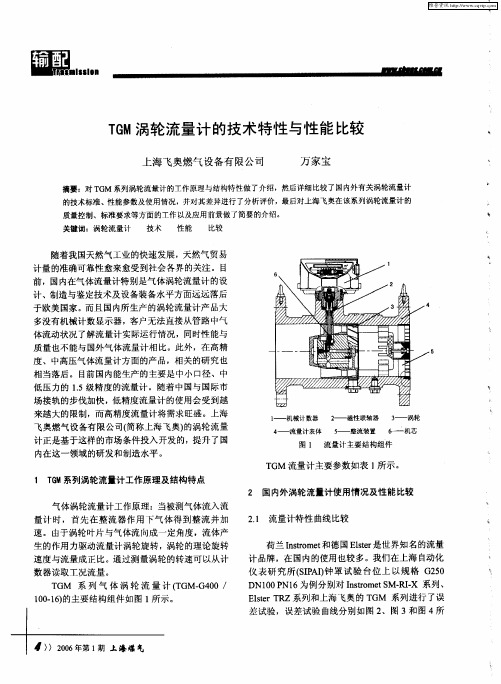
TGM涡轮流量计的技术特性与性能比较
25
蔷L 5
n5 n5 Fra bibliotek从图上我们可以看出T M— 2010 G G 5 / 的流量特 0 性 曲线与上述两种国 内使用 量最大的进 口涡轮流 量 计产 品特性 曲线 非 常接近 。 个 流量 段 Is o t 整 nt me r 产品起伏较小, 线性较平缓 , 小流量段变化也不大:
I L
.
0
4 U o u
——’’’-一
计 设计 欧洲标 准 。由于 欧洲标 准 在方 便用 户 、环 保
2 国内外涡轮流量计使用情 况及性能 比较
气 体 涡轮流 量 计工作 原理 :当被测气 体 流入 流 量 计 时 ,首 先 在 整 流 器 作 用 下 气 体 得 到 整 流 并 加 速 。由于 涡轮 叶片 与气 体流 向成 一 定角度 ,流体 产
21 流量计特性 曲线比较 .
荷兰 Is o t 德 国 Es r nt me和 r le是世 界 知 名 的流量 t
与 Is o t 比 ,Es r 品整个 流 量段 的线 性 也 nt me相 r le 产 t
.
1 . 5
较平缓,小流量段变化略大 ;T M 产 品整个流量 G
_5 2
段线性变化也不大,而小流量段变化则明显大于上 述两种 国外 品牌 ,但都在误差允许范围以内。
图 2 荷兰 is o tM.I 5 0 nt meS R . G2 0 r X DN10型产 品性能
生的作用力驱动流量计涡轮旋转 , 涡轮的理论旋转 速度 与 流量 成正 比。通 过测 量 涡轮 的转 速可 以从计
数器 读 取工 况流 量 。
计品牌,在 国内的使用也较多。我们在上海 自 动化 仪表研 究所(I I  ̄ SP ) 罩试验 台位 上 以规格 G 5 A  ̄ 20 D 0 N1 为例分别对 Is o e S R — 系列、 N10 P 6 nt m t M-I r X Es rT Z 系列 和上 海 飞奥 的 T le R t GM 系列 进行 了误 差试验 ,误差试验 曲线分别如图 2 、图 3和图 4所
OMEGA FMA-700A 和 FMA-800A 系列流量计与控制器说明书
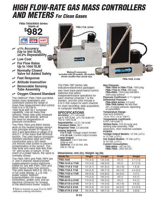
Current Consumption: FMA-800A: <45 mA DC FMA-700A: <250 mA DC
Dimensions: mm (in); Weight: kg (lb)
Model No.
FMA-78C50 208 15 m (50') interconnect cable with connectors
FPW-15
75 15 Vdc power supply**
Note: All flow ranges are specified for nitrogen or air. When used for other gases, a correlation factor is used to determine flow rate.
Power: 117 Vac ±10%, 50 to 60 Hz, 50 Watts Dimensions: 215.9 W x 123.8 H x 247.7 mm D (81⁄2 x 47⁄8 x 93⁄4") Display: 0 to 102.4%
Rate Indicators/Electronics Boxes
HIGH FLOW-RATE GAS MASS CONTROLLERS AND METERS For Clean Gases
FMA-700A/800A Series Starts at
$982
FMA-775A, $2998.
Optional†
ߜ ±1% Accuracy (Up to 500 SLM), ±0.2% Repeatability
OMEGA FPU100 Series和FPU250 Series 可变速流量计说明书
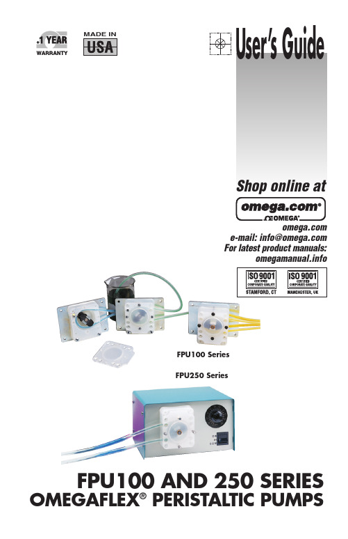
FPU100 Series FPU250 SeriesFPU100 AND 250 SERIESOMEGAFLEX ®PERISTALTIC PUMPSe-mail:**************For latest product manuals:User’sGuideShop online atINTRODUCTIONGeneral DescriptionThe OMEGA®peristaltic pump is self-priming and can handle a widevariety of viscosities (from air to heavy slurries) with positivedisplacement.The OMEGA®peristaltic pump can be used to pump fluids or gaseswithout contamination of the pump - the material contacts only thetubing. The positive displacement feature makes this pump ideal formetering applications. Each revolution of the roller assembly delivers aprecise amount of fluid.The easy changeability of the OMEGA®peristaltic pump tubing makesthis the ideal pump for diverse quick change repetitive pumping jobs.Flexible, reliable and cost efficient, the OMEGA®peristaltic pump canfill most all of your fluid movement requirements.Specifications1.Priming Unit is self-priming and will hold vacuum when turnedoff.2.Operation: Pump can run dry without damage.3.Weight: See model information chart.4.Capacity: From 3mL/min to 987mL/min (see model informationchart).5.Construction: High strength plastics and long-lasting alloy metals.6.Maximum Head Pressure: 57 feet of water.7.Maximum Suction Lift: 28 feet of water.8.Maximum System Pressure: 20 psi continuous, 25 psi intermittent.9.Certification: All motors are UL listed.10.Rating: All gearmotors are rated for 100% continuous duty.2OPERATIONAL INFORMATIONInstallation InstructionsPower Requirements: Voltage and frequency of power supply must bethe same as shown on unit.Wiring Connections: All wiring and electrical connections must complywith national electrical codes and local electrical codes.Mounting:a) Mount OEM model mounting bracket to any flat, rigid surface, usingfour #10-32 screws.b) Case enclosed model may be placed on any flat surface, assuringspace is provided at the back of the case for air circulation throughventilation holes.Mounting Location: Pump should be used in a dry location with anadequate supply of cooling air. The ambient temperature should notlocations.Instructions for Optional Timer1. Rotate the program disc in the direction of the arrows to align thecorrect time of day with the time mark.2. Set the desired switching program by pushing the switch actuatorstoward the center of the time switch. Each actuator provides a 15minute “ON” time. The now visible orange area(s) indicate theswitch “ON” period3FPU SERIESROLLER & TUBING SELECTIONUse the following color coded rollers with the appropriate tubing ID: Roller Color Tubing ID mL Per RevolutionBlack1⁄4" 3.5Black3⁄16" 2.1Red1⁄8"0.84Red1⁄6"0.21Instructions for 1/16" Tubing AssemblyInsert 1⁄16" tubing into the sleeve and pull out desired length of 1⁄16"tubing. Secure 1⁄16" tubing by placing the tie fastener approximately 1⁄4"from one end of the sleeve and tighten fastener so that 1⁄16" tubing is noteasily moved. Be careful not to collapse the inner tubing by over-tightening the tie fastener. Install the tubing with the tie fastener on theinlet side of the pump.Make sure the tie fastener is on the outside of the pumphousing and is not interfering with the roller assembly.4ASSEMBLY INSTRUCTIONS1. Assemble mounting plate (4) and pump housing (5) to gearmotor (3)with with three #10-32 x 11⁄4" long screws and one #8-32 x 7⁄8" longscrew (2).2. Slide white plastic washer (8) onto motor shaft. Press roller bracketassembly (9) onto the motor shaft with the four self-locking teethtoward the gearmotor. (As shown in the view above.)3. Insert tubing (6) into pump. housing (5) inlet and work tube intoroller race as you rotate the roller bracket assembly. See details onpage 5.4. Assemble pump cover (10) to pump housing. (5) with four #8-32 x 5⁄8"long screws (11).5TUBE INSPECTION AND REPLACEMENTTubing Inspection:Inspect all tubing regularly and replace it if deterioration occurs. Usethe following instructions to replace pump tubing.Tubing Replacement1. Disconnect the power to the pump.2. Disconnect the suction and discharge tubing from the tubing.3. Remove four screws and pump cover.4. Remove old pump tubing and discard.5. Clean roller race, removing any particles that could damage tubing.6. Position the roller bracket assembly as shown in Fig. 1.7. Push the new tubing into the inlet port anchoring the tubing ingrippers (see Fig. 2) while rotating the roller bracket assembly.8. Continue to rotate the roller bracket assembly, pushing the tubinginto the roller race.9. Finally, insert the tubing into the outer port (Fig. 4), and replace thecover and screws.6OMEGA®VARIABLE SPEED DRIVESSERIES FPU 250OMEGA®variable speed drives are powered by a DC gearmotor. Aspecially designed electronic speed control system provides smoothacceleration control over the entire flow range. The three positionon/off switch allows the user to maintain speed setting when unit isturned off or reversed. This unit is designed for continuous operation atany speed. All variable speed drives are rated for continuous duty at25°C ambient.Fuse: Replace with type AGC-1/2 Amp. Use AGC-1 Amp for dual headpump.Alternate Tubing Replacement Method for Medium and HighVariable Speed UnitsWith unit running at high RPM, pull old tubing out from outlet port ofpump. Install new tube by inserting into inlet port; continue feedingtube 1⁄4" in at a time, allowing the roller assembly to push tubing untiltube extends out from outlet port. Pull tubing from outlet port untildesired tubing extension is obtained. Run unit for about one minute toallow tube to seat properly.Depending on pump model, tubing in use and fluid beingpumped, roller assembly may stop rotating whenspeed/flow control is set at the low end range. Avoidprolonged operation in the stalled position for longer motorlife.78FPU SERIES - AC MODELS, OEM Style, Fixed SpeedFPU SERIES - DC MODELS, OEM Style, Fixed Speed910NOTES:11M1116-0404It is the policy of OMEGA Engineering, Inc. to comply with all worldwide safety and EMC/EMI regulations that apply. OMEGA is constantly pursuing certification of its products to the European New Approach Directives. OMEGA will add the CE mark to every appropriate device upon certification.The information contained in this document is believed to be correct, but OMEGA accepts no liability for any errors it contains, and reserves the right to alter specifications without notice.WARNING: These products are not designed for use in, and should not be used for, human applications.WARRANTY/DISCLAIMEROMEGA ENGINEERING, INC. warrants this unit to be free of defects in materials and workmanship for a period of 13 months from date of purchase. OMEGA’s WARRANT Y adds an additional one (1) month grace period to the normal one (1) year product warranty to cover handling and shipping time. T his ensures that OMEGA’s customers receive maximum coverage on each product.If the unit malfunctions, it must be returned to the factory for evaluation. OMEGA’s Customer Service Department will issue an Authorized Return (AR) number immediately upon phone or written request. Upon examination by OMEGA, if the unit is found to be defective, it will be repaired or replaced at no charge. OMEGA’s WARRANTY does not apply to defects resulting from any action of the purchaser, including but not limited to mishandling, improper interfacing, operation outside of design limits, improper repair, orunauthorized modification. This WARRANTY is VOID if the unit shows evidence of having been tampered with or shows evidence of having been damaged as a result of excessive corrosion; or current, heat, moisture or vibration; improper specification;misapplication; misuse or other operating conditions outside of OMEGA’s control. Components in which wear is not warranted,include but are not limited to contact points, fuses, and triacs.OMEGA is pleased to offer suggestions on the use of its various products. However, OMEGA neither assumes responsibility for any omissions or errors nor assumes liability for any damages that result from the use of its products in accordance with information provided by OMEGA, either verbal or written. OMEGA warrants only that the parts manufactured by the company will be as specified and free of defects. OMEGA MAKES NO OTHER WARRANTIES OR REPRESENTATIONS OF ANY KIND WHATSOEVER, EXPRESSED OR IMPLIED, EXCEPT THAT OF TITLE, AND ALL IMPLIED WARRANTIES INCLUDING ANY WARRANTY OF MERCHANTABILITY AND FITNESS FOR A PARTICULAR PURPOSE ARE HEREBY DISCLAIMED. LIMITATION OF LIABILITY: The remedies of purchaser set forth herein are exclusive, and the total liability of OMEGA with respect to this order, whether based on contract, warranty, negligence, indemnification, strict liability or otherwise, shall not exceed the purchase price of the component upon which liability is based. In no event shall OMEGA be liable for consequential,incidental or special damages.CONDITIONS: Equipment sold by OMEGA is not intended to be used, nor shall it be used: (1) as a “Basic Component” under 10 CFR 21 (NRC), used in or with any nuclear installation or activity; or (2) in medical applications or used on humans. Should any Product(s)be used in or with any nuclear installation or activity, medical application, used on humans, or misused in any way, OMEGA assumes no responsibility as set forth in our basic WARRANTY/ DISCLAIMER language, and, additionally, purchaser will indemnify OMEGA and hold OMEGA harmless from any liability or damage whatsoever arising out of the use of the Product(s) in such a manner.RETURN REQUESTS /INQUIRIESDirect all warranty and repair requests/inquiries to the OMEGA Customer Service Department. BEFORE RET URNING ANY PRODUCT (S) T O OMEGA, PURCHASER MUST OBT AIN AN AUT HORIZED RET URN (AR) NUMBER FROM OMEGA’S CUST OMER SERVICE DEPART MENT (IN ORDER T O AVOID PROCESSING DELAYS). T he assigned AR number should then be marked on the outside of the return package and on any correspondence.The purchaser is responsible for shipping charges, freight, insurance and proper packaging to prevent breakage in transit. FOR WARRANTY RETURNS, please have the following informa-tion available BEFORE contacting OMEGA:1.Purchase Order number under which the product was PURCHASED,2.Model and serial number of the product under warranty, and3.Repair instructions and/or specific problems relative to the product.FOR NON-WARRANTY REPAIRS,consult OMEGA for cur-rent repair charges. Have the following information avail-able BEFORE contacting OMEGA:1. Purchase Order number to cover the COST of the repair,2.Model and serial number of the product, and3.Repair instructions and/or specific problems relative to the product.OMEGA’s policy is to make running changes, not model changes, whenever an improvement is possible. This affords our customers the latest intechnology and engineering.OMEGA is a registered trademark of OMEGA ENGINEERING, INC.© Copyright 2008 OMEGA ENGINEERING, INC. All rights reserved. T his document may not be copied, photocopied, reproduced, translated, or reduced to any electronic medium or machine-readable form, in whole or in part, without the prior written consent of OMEGA ENGINEERING, INC.Servicing North America:U.S.A.:One Omega Drive, Box 4047ISO 9001 Certified Stamford, CT 06907-0047Tel: (203) 359-1660FAX: (203) 359-7700e-mail:**************Canada:976 BergarLaval (Quebec) H7L 5A1, Canada Tel: (514) 856-6928FAX: (514) 856-6886e-mail:*************For immediate technical or application assistance:U.S.A. andSales Service: 1-800-826-6342/1-800-TC-OMEGA Canada:Customer Service: 1-800-622-2378/1-800-622-BEST Engineering Service: 1-800-872-9436/1-800-USA-WHEN Mexico:En Espan ˜ol: (001) 203-359-7803e-mail:*****************FAX: (001) 203-359-7807**************.mxServicing Europe:Czech Frystatska 184, 733 01 Karviná, Czech Republic Republic:TEL: +420 (0)59 6311899FAX: +420 (0)59 6311114Tol Free: 0800-1-66342e-mail:*****************Germany/Daimlerstrasse 26, D-75392 Deckenpfronn, Germany Austria:Tel: +49 (0)7056 9398-0FAX: +49 (0)7056 9398-29TollFreeinGermany************e-mail:*************United One Omega Drive, River Bend Technology Centre Kingdom:Northbank, Irlam, ManchesterISO 9001 Certified M44 5BD United KingdomTel: +44 (0)161 777 6611FAX: +44 (0)161 777 6622Toll Free in United Kingdom: 0800-488-488e-mail:**************.uk。
TBQZ系列智能气体涡轮流量计

4.2 选型实例 已知某一供气管线实际工作压力范围为表压0.8MPa~1.2MPa, 介质温度范围为-100C~+400C,供气峰值为标准体积流量2000m3/h, 供气谷值为标准体积流量3500m3/h。经取样分析计算天然气之真 实相对密度Gr=0.591,N2摩尔百分含量为Mn=1.6%,CO2摩尔百分 含量为Mc=0.8%,当地大气压为101.325kPa,要求确定流量计之口 径。 当介质压力为0.8MPa、温度为400C时,压缩因子影响最小, 此时当处于供气峰期时,具有最大体积流量。而当介质压力为 1.2MPa、温度为100C时,压缩因子影响最大,此时当处于供气谷 期时,具有最小体积流量。
采用RS485接口与上位机联网,每台上位机可带32台流量计,且只 须两根通讯线,安装费用低;采用RS485接口与数据采集器配套, 可通过电话网络或宽带网络构成自动读表与管理系统,自动化程 度高,且便于用户集中管理。 流量计表头可180度旋转,安装使用简单方便。 本系列产品执行国家JJG-94《速度式流量计检定规程》和 Q/ZTX11-2004《气体涡轮流量计》产品企业标准。主要性能参数 符合IS09951标准的要求。 本系列产品有隔爆和本安两种防爆型式,经国家级仪器仪表防 爆安全监督检验站(NEPSI)检定认可,符合国家标准GB3836.12000、GB3836.2-2000、GB3836.4-2000的有关规定。隔爆型防爆 标志为ExdIIBT4,本安型防爆标志ExiaIICT4。
3.7 网络通信管理软件功能 流量计与数据采集器配套,可通过电话线进行传输,对网络 中的每台流量计的历史数据及参数进行读取与设置,同时通信管 理软件可实现完善的管理功能。 3.8 防爆标志:ExdIIBT4:ExiaIICT4 3.9 防护等级:IP65
青岛奥博仪表设备有限公司-气体涡轮流量计说明书
青岛奥博仪表设备有限公司目录1、用途: (1)2、工作原理: (1)3、特点: (1)4、主要技术参数: .............................1-25、仪表结构及安装方式: .......................2-36、电气特性...................................3-47、安装尺寸 (4)8、附录-现场显示型仪表操作说明................5-13一、用途:气体涡轮流量计是一种速度式仪表。
它具有精度高、重复性好、结构简单、测量范围宽、体积小、重量轻、压力损失小、维修方便等优点。
可广泛应用于石油、化工、冶金、城市燃气管网等行业。
尤其在城市燃气计量,输配管网计量以及燃气调压站计量中得到了广泛应用。
二、工作原理:3、使用条件:(1)环境温度:-20℃~50℃;(2)相对湿度:5%~95%;(3)被测介质温度:-20℃~80℃;(4)大气压力:86Kpa~106Kpa;(5)防爆等级:ibⅡBT4。
4、流量计特性曲线图:五、仪表结构及安装方式:图a图bLWQ DN≤40mm安装示意图LWQ DN≥ 50MM安装示意图1、仪表安装采用法兰连接、螺纹连接及夹装式;2、安装时气体流动方向应与传感器外壳上指示流向的箭头方向一致,且上游直管段应≥10DN,下游直管段应≥5DN(DN为管道内径);3、安装前检查仪表叶轮的灵活性,用微量气体吹向涡轮,叶轮应灵活转动、计数器工作正常,无噪音和突停、卡滞现象;4、严禁带表焊接法兰,并严格清理过滤器和流量计之间的上游直管段,直管段中不得有残留焊渣及其他杂物;5、按安装图要求安装并检查整个系统密封性,保证无气体泄露现象;6、为了检修时不影响气体的正常输送,应在传感器的安装处安装旁通管道(见图c)。
图c 传感器安装管道示意图六、电气特性:在测量系统中,累计流量的表达方式为:V=N/K;在测量系统中,瞬时流量的表达方式为:Q=(f/K)×3600;由于K值在较宽的测量范围内并非单一值,它是信号频率的函数。
OMEGA 流量计说明书

FtB-406A, shown smaller than actual size.
F
Use the FtB-400A Series turbine flow meter with the DPF701 Series flow indicator.
SPeCIFICAtIoNS
Accuracy & Linearity: ±0.5% of reading or better Repeatability: ±0.1% of reading or better temperature Range: -268 to 232°C (‑450 to 450°F) Signal output: 10 mV rms or greater into a 10 kΩ load at minimum flowrate
Suitable For Cleaning Out Of Place (COP).
The Omega FTB400-Series Sanitary
Design Turbine Flowmeter is
designed and manufactured to be
compliant with the ASME
equipment used in the production
of biopharmaceuticals. This series
includes 11 sizes, ¼” to 3” with
standard Tri-Clamp™ fittings, covering flow rates for 0.35 to 650 GPM.
Comes complete with operator’s manual and 10 point NIST calibration certificate.
上海罗托克自动化仪表 QWLJ 系列气体涡轮流量计 说明书

~l号,提醒用户更换电池。
但此时并不影响流量计的正常运行,用户应在电池欠压标志出现后的一个星期内更换电池。
在三线制供电时背景光有效,背景光亮度分三级可调。
可通过面板按键中“数据[DAT]”键进行循环调节,调节顺序依次为“亮”、“较亮”、“暗”。
2.流量计累积数据的保存流量计在断电时(无论内外部供电),所显示的累积流量都会瞬间保存在流量计的存贮单元中,以防止意外断电造成的漏计现象,且所有的运行参数也会保存。
待供电恢复流量计又将正常运行。
3.面板按键的使用面板上共四个功能键,分别为设置键[SET]、移位键[MOV]、数据键[DAT]、复位键[RST],各键功能如下:■设置键[SET]:进入流量计“设置模式”。
■移位键[MOV]:“运行模式”下用于进入“历史数据查询模式”,在“设置模式”下用于执行设置位的移位。
■数据键[DAT]:“运行模式”下用于设置背景光亮度(此时流量计已由外部三线制DC+24V供电,否则无效),在“设置模式”下执行设置位的数据设置。
■复位键[RST]:“运行模式”下用于锁定/解锁显示屏下屏的显示数据(即控制显示屏下屏数据的固定显示方式或循环显示方式),在“设置模式”下则为切换到“运行模式”(此时如果参数有所更改将会自动保存)。
4.红外遥控器(可选)的使用红外遥控器共8个按键分别为:“1”、“2”、“3”、“4”、“5”、“6”、“△”、“▽”,各键功能为:“1,5”键等同xx:xx XX-XX-XX 显示第1次的断电时间记录如果断电次数超过5次,那么第6次的断电时间记录将覆盖第1次的断电时间记录,第7次的断电时间记录将覆盖第2次的断电时间记录,以此类推。
3 第3次按MOV键2xx:xx XX-XX-XX 显示第3次的断电时间记录5第5次按MOV 键4xx:xx XX-XX-XX显示第5次的 断电时间记录7第7次按MOV 键XXXXXXXXX m3 xx:xx XX-XX-XX 按月查询此时按DAT 键将依次查询前 12个月每月的净流量 8 第8次按MOV 键 XXXXXXXXX m3 xx:xx XX-XX-XX 按日查询 此时按DAT 键将依次查询前 31天第天的净流量9第9次按MOV 键返回次序1状态以此循环按RST 键后,返回到工作模式。
气体涡街流量计工作原理参考资料
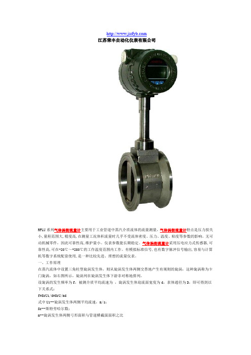
江苏荣丰自动化仪表有限公司RFLU系列气体涡街流量计主要用于工业管道中蒸汽介质流体的流量测量,气体涡街流量计特点是压力损失小,量程范围大,精度高,在测量工况体积流量时几乎不受流体密度、压力、温度、粘度等参数的影响。
无可动机械零件,因此可靠性高,维护量小。
仪表参数能长期稳定。
气体涡街流量计采用压电应力式传感器,可靠性高,可在-20℃~+250℃的工作温度范围内工作。
有模拟标准信号,也有数字脉冲信号输出,容易与计算机等数字系统配套使用,是一种比较先进、理想的流量仪表。
一、工作原理在蒸汽流体中设置三角柱型旋涡发生体,则从旋涡发生体两侧交替地产生有规则的旋涡,这种旋涡称为卡门旋涡,如右图所示,旋涡列在旋涡发生体下游非对称地排列。
设旋涡的发生频率为f,被测介质平均流速为,旋涡发生体迎流面宽度为d,表体通径为D,即可得到以下关系式:f=SrU1/d=SrU/md式中U1--旋涡发生体两侧平均流速,m/s;Sr--斯特劳哈尔数;m--旋涡发生体两侧弓形面积与管道横截面面积之比管道内体积流量qv为qv=πD2U/4=πD2mdf/4SrK=f/qv=[πD2md/4Sr]-1式中 K--流量计的仪表系数,脉冲数/m3(P/m3)。
K除与旋涡发生体、管道的几何尺寸有关外,还与斯特劳哈尔数有关。
斯特劳哈尔数为无量纲参数,它与旋涡发生体形状及雷诺数有关,图2所示为圆柱状旋涡发生体的斯特劳哈尔数与管道雷诺数的关系图。
由图可见,在ReD=2×10⁴~7×10⁶范围内,Sr可视为常数,这是仪表正常工作范围。
当测量气体流量时,VSF的流量计算式为(4)斯特劳哈尔数与雷诺数关系曲线式中 qVn,qV--分别为标准状态下(0oC或20oC,101.325kPa)和工况下的体积流量,m3/h;Pn,P--分别为标准状态下和工况下的绝对压力,Pa;Tn,T--分别为标准状态下和工况下的热力学温度,K;Zn,Z--分别为标准状态下和工况下气体压缩系数。
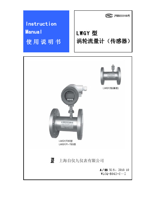
上海自仪九仪表 LWGY 型 涡轮流量计(传感器) 说明书
本产品执行标准:JB/T 9246-1999
安装和使用传感器之前请阅读本说明书,并请按照本说明书进行操作。 如果用户有不同于本说明书所述的传感器的安装、使用、要求,或改进的建议, 请与本公司联系。
1
二、选型编码
项目及内容
代
涡轮流量传感器
公称通径(mm) 4 (G 螺纹连接) 6 (G 螺纹连接) 10 (G 螺纹连接) 15 (G 螺纹连接) 25 (G 螺纹连接) 32 40 50 65 80 100 (125) 150 200
1 工作原理 放大器采用运算放大器作平衡输入放大,施密特触发整形。具有温度稳定性能好、
放大系数高、抗干扰性能好、负载能力强等特点。见图 2。
2 技术性能 z 频率范围:10~5000 Hz z 输出波形:矩形波 高电平:供电电压—2V; 低电平:<1V (负载阻抗 10kΩ时) z 供电电压:直流 12 V z 消耗电流:10 mA z 工作环境温度:-25~+50℃ z 环境相对湿度:35%~85%
注:若压力等级(公称压力)是选型编码中没有的,则公称压力代码为:“Z”,并将 公称压力和标准写明。
4
四、基本结构与工作原理
1 基本结构 传感器的基本结构如图 1 所示,主要由壳体、前导向架、轴、叶轮、后导向架、压
紧圈和带磁电感应转换器的放大器等组成。 前导向架和后导向架安装在壳体中,轴安装在导向架上,同时因导向架上有几片呈
DN4~15 DN25~DN250
A
DN4~15
1
D
3
A
B
C
C
D
T
0
1 2
3
3
4
/D /D
—(最大流量) —K
选型举例:LWGY-15A1D3C3/D 表示:涡轮流量传感器,公称通径:15mm,特征代号:普通型(硬质 合金轴+宝石轴承),材料:双相不锈钢 SUS329J1,压力等级:PN6.3MPa,精度等级:0.5 级,输出: 4~20mA 标准直流电流信号输出,显示:现场瞬时流量和累积总量显示(TBS 型),防爆等级:隔爆型。
- 1、下载文档前请自行甄别文档内容的完整性,平台不提供额外的编辑、内容补充、找答案等附加服务。
- 2、"仅部分预览"的文档,不可在线预览部分如存在完整性等问题,可反馈申请退款(可完整预览的文档不适用该条件!)。
- 3、如文档侵犯您的权益,请联系客服反馈,我们会尽快为您处理(人工客服工作时间:9:00-18:30)。
A d v . - Y I D I C I - S h a n g h a i - E d . 09-2006 1000 c o p i e s MARKETING NETWORKS
TGM EXPLORER FT
Company Profile Company Aptitude
Pietro Fiorentini spa is an international market leader offering a wide range of products and services that meets all the requirement of modern production, transportation, and distribution of natural gas.
Shanghai Fiorentini gas equipment Co., Ltd., as the engaged in research, development, design, manufacture, sales and technical service for gas reducing and metering stations Shanghai Fiorentini commits herself to working on the integrated technology of gas reducing and metering as well as the total solutions. Our product lines include:
integrated pressure reducing system: gas reducing & metering stations, medium-high pressure city gates, compressed natural gas reducing stations, and two-stage reducing stations etc.,
pressure vessels: filters, filtering separators, cyclone separators, heat exchangers, water bath heaters, insulating joints, and pig launching equipment etc.,
monitoring system: gas management information system, SCADA gas distribution monitoring system, station-control system, etc.,
valves products: pressure regulators, slam-shut valves, flow control valves, ball valves and butterfly valves etc.,measuring products: gas turbine meters, orifice meters, volume corrector, flow computer, etc.
We have also provided the suitable and perfect solutions as well as the systems to thousands of users from city, power plant, chemical and metallurgy for the different requirements of gas transmission, treatment, reducing, meter and monitoring in the various natural gas up, middle and downstream application. A part from serving the customers in China, we start to provide products and technologies to Asia-Pacific area.
Fiorentini Group, with six production premises, and many commercial branches all over the world, builds up global production and service networks, as well as in China by Shanghai Fiorentini. The expansive and developing networks provide a firm guarantee to offer the high quality services and total solutions to the customers locally and internationally.
first and meanwhile the largest joint venture for gas transmission and distribution, is always an industrial pioneer of natural gas in China.
Company Values
TGM TGM
EXPLORER FT。
