(完整)ADC参数定义
高速ADC几个关键指标的定义

高速ADC几个关键指标的定义介绍高速ADC几个指标的定义一个基本概念分贝(dB):按照对数定义的一个幅度单位。
对于电压值,dB以20log(V A/V B)给出;对于功率值,以10log(P A/P B)给出。
dBc是相对于一个载波信号的dB值;dBm是相对于1mW的dB值。
对于dBm而言,规格中的负载电阻必须是已知的(如:1mW提供给50Ω),以确定等效的电压或电流值。
静态指标定义:量化误差(Quantization Error)量化误差是基本误差,用图3所示的简单3bit ADC来说明。
输入电压被数字化,以8个离散电平来划分,分别由代码000b到111b去代表它们,每一代码跨越Vref/8的电压范围。
代码大小一般被定义为一个最低有效位(Least Significant Bit,LSB)。
若假定Vref=8V时,每个代码之间的电压变换就代表1V。
换言之,产生指定代码的实际电压与代表该码的电压两者之间存在误差。
一般来说,0.5 LSB偏移加入到输入端便导致在理想过渡点上有正负0.5LSB的量化误差。
图3 理想ADC转换特性偏移与增益误差(Offset Gain Error)器件理想输出与实际输出之差定义为偏移误差,所有数字代码都存在这种误差。
在实际中,偏移误差会使传递函数或模拟输入电压与对应数值输出代码间存在一个固定的偏移。
通常计算偏移误差方法是测量第一个数字代码转换或“零”转换的电压,并将它与理论零点电压相比较。
增益误差是预估传递函数和实际斜率的差别,增益误差通常在模数转换器最末或最后一个传输代码转换点计算。
为了找到零点与最后一个转换代码点以计算偏移和增益误差,可以采用多种测量方式,最常用的两种是代码平均法和电压抖动法。
代码平均测量就是不断增大器件的输入电压,然后检测转换输出结果。
每次增大输入电压都会得到一些转换代码,用这些代码的和算出一个平均值,测量产生这些平均转换代码的输入电压,计算出器件偏移和增益。
(完整)ADC参数定义

ADC测试参数定义、分析及策略之动态测试2007-11—08 10:50:21分类:前言混合信号技术给当今的半导体制造商们带来了很多新挑战,以前一些对数字电路只有很小影响的缺陷如今在嵌入式器件中却可能大大改变模拟电路的功能,导致器件无法使用。
为确保这些新型半导体器件达到“无缺陷”水平,需要开发新的测试策略、方法与技术。
本文将结合一个简单的混合信号器件——模数转换器(AD C)来对这些策略、技术与方法进行讨论,说明混合信号器件测试的步骤和方法。
有了这些基本认识后,就可将其扩展并应用到当前先进的嵌入式半导体器件中,如数字滤波器、音频/视频信号处理器及数字电位计等。
传统半导体器件测试包括基本参数测试(连续性、泄漏、增益等)和功能测试(将器件输出与给定输入相比较),混合信号测试还要再另外增加两个测试,即动态测试和线性测试.动态参数描述的是器件对一个特定频率或多频率时序变化信号的采样(从模拟信号中建立数字波形)和重现(利用数字输入建立模拟信号)能力。
线性参数则相反,描述的是器件内在特性,主要关注数字和模拟电路之间的关系.下面将对这两种特性分别作详细说明。
动态测试模数转换器的动态特性有时也称作传输参数,代表器件模拟信号采样和输入波形的数字再现能力,信噪比(S NR)、总谐波失真(THD)及有效位数(ENOB)等指标可使制造商对器件输出的“纯度”和数字信息精度进行量化。
新型动态测试技术产生于上世纪80年代,主要围绕数字信号处理和傅立叶变换,将时域波形和信号分别转换为频谱成分.这种技术可以同时对多个测试频率进行采样,效率和重复性非常高.图1是对一个普通ADC 器件进行快速傅立叶变换(FFT)测试的示意图,图中可以看到模拟信号在时域内转换成数字代码,然后用傅立叶变换转换成频谱。
对ADC输出进行傅立叶分析可提供宝贵的性能信息,但如果测试时条件设置不当得到的信息也会毫无意义。
为了从器件输出信号的傅立叶分析中提取有意义的性能参数,在讨论FFT结果之前首先需要考虑测试条件,其中包括输入信号完整性、采样频率、一致性及系统测量误差(假频、量化及采样抖动误差)。
ADC参数解释
ADC参数解释1.分辩率(Resolution) 指数字量变化一个最小量时模拟信号的变化量,定义为满刻度与2n的比值。
分辩率又称精度,通常以数字信号的位数来表示。
2.转换速率(Conversion Rate)是指完成一次从模拟转换到数字的AD转换所需的时间的倒数。
积分型AD的转换时间是毫秒级属低速AD,逐次比较型AD是微秒级属中速AD,全并行/串并行型AD可达到纳秒级。
采样时间则是另外一个概念,是指两次转换的间隔。
为了保证转换的正确完成,采样速率(Sample Rate)必须小于或等于转换速率。
因此有人习惯上将转换速率在数值上等同于采样速率也是可以接受的。
常用单位是ksps和Msps,表示每秒采样千/百万次(kilo / Million Samples per Second)。
3.量化误差(Quantizing Error) 由于AD的有限分辩率而引起的误差,即有限分辩率AD的阶梯状转移特性曲线与无限分辩率AD(理想AD)的转移特性曲线(直线)之间的最大偏差。
通常是1个或半个最小数字量的模拟变化量,表示为1LSB、1/2LSB。
4.偏移误差(Offset Error) 输入信号为零时输出信号不为零的值,可外接电位器调至最小。
5.满刻度误差(Full Scale Error) 满度输出时对应的输入信号与理想输入信号值之差。
6.微分非线性(Differential nonlinearity,DNL)ADC相邻两刻度之间最大的差异。
7.积分非线性(Integral nonlinearity,INL)表示了ADC器件在所有的数值点上对应的模拟值和真实值之间误差最大的那一点的误差值,也就是输出数值偏离线性最大的距离。
8.总谐波失真(Total Harmonic Distotortion缩写THD)。
ADC的选择,首先看精度和速度,然后看输入通道数,输出的接口如SPI或者并行的,差分还是单端输入的,输入范围是多少。
ADC参数解释和关键指标
第五章ADC 静态电参数测试(一)翻译整理:李雷本文要点:ADC 的电参数定义ADC 电参数测试特有的难点以及解决这些难题的技术ADC 线性度测试的各类方法ADC 数据规范(Data Sheet)样例快速测试ADC 的条件和技巧用于ADC 静态电参数测试的典型系统硬件配置关键词解释失调误差 Eo(Offset Error):转换特性曲线的实际起始值与理想起始值(零值)的偏差。
增益误差E G(Gain Error):转换特性曲线的实际斜率与理想斜率的偏差。
(在有些资料上增益误差又称为满刻度误差)线性误差Er(Linearity Error):转换特性曲线与最佳拟合直线间的最大偏差。
(NS 公司定义)或者用:准确度E A(Accuracy):转换特性曲线与理想转换特性曲线的最大偏差(AD 公司定义)。
信噪比(SNR): 基频能量和噪声频谱能量的比值。
一、ADC 静态电参数定义及测试简介模拟/数字转换器(ADC)是最为常见的混合信号架构器件。
ADC是一种连接现实模拟世界和快速信号处理数字世界的接口。
电压型ADC(本文讨论)输入电压量并通过其特有的功能输出与之相对应的数字代码。
ADC的输出代码可以有多种编码技术(如:二进制补码,自然二进制码等)。
测试ADC 器件的关键是要认识到模/数转换器“多对一”的本质。
也就是说,ADC 的多个不同的输入电压对应一个固定的输出数字代码,因此测试ADC 有别于测试其它传统的模拟或数字器件(施加输入激励,测试输出响应)。
对于 ADC,我们必须找到引起输出改变的特定的输入值,并且利用这些特殊的输入值计算出ADC 的静态电参数(如:失调误差、增益误差,积分非线性等)。
本章主要介绍ADC 静态电参数的定义以及如何测试它们。
Figure5.1:Analog-to-Digital Conversion Process. An ADC receives an analog input and outputs the digital codes that most closely represents then input magnitude relative to full scale.1.ADC 的静态电参数规范ADC的静态电参数主要验证器件的输入-输出转换曲线符合设计(理想)曲线的程度。
adc 基本概念、逻辑概念和物理概念

adc 基本概念、逻辑概念和物理概念ADC是模拟数字转换器(Analog to Digital Converter)的英文简称,它是一种将模拟信号转换为数字信号的设备或模块。
ADC在现代电子系统中起着非常重要的作用,它可以将来自传感器、麦克风、摄像头等模拟信号转换为数字信号,以便数字处理器进行处理和分析。
在本文中,我们将从基本概念、逻辑概念和物理概念三个方面来探讨ADC的工作原理和应用。
首先,我们来看一下ADC的基本概念。
ADC的基本原理是根据一定的采样频率对模拟信号进行采样,并将采样值按照一定的编码规则转换为数字信号。
其中,采样频率表示每秒钟采集模拟信号的次数,而编码规则则决定了数字信号的精度和范围。
通常来说,ADC的输出是一个n位的二进制数,其取值范围为0到2的n次方减1。
因此,ADC的精度可以通过比特数来表示,比如8位ADC的输出精度为256个离散值。
其次,我们来谈一下ADC的逻辑概念。
在数字系统中,ADC通常作为一个独立的模块,负责将模拟信号转换为数字信号。
它可以通过串行接口(如SPI、I2C)或并行接口(如并行总线)与其他数字器件进行通信。
在实际应用中,ADC的转换结果可以直接用于数字信号处理器(DSP)、微控制器(MCU)或FPGA进行进一步处理。
此外,为了提高系统的灵敏度和精度,可能还会使用ADC前置放大器、数字滤波器等辅助器件。
最后,我们来探讨ADC的物理概念。
ADC通常由模拟前端、数字处理器和接口电路等部分组成。
其中,模拟前端用于对模拟信号进行采样、滤波和放大,以保证转换的准确性和稳定性;数字处理器负责将模拟信号转换为数字信号,并进行存储、加工和输出;而接口电路用于与其他数字设备之间进行通信和数据传输。
此外,ADC的性能参数还包括转换速率、信噪比、非线性度等,这些参数直接影响了其在实际应用中的性能和稳定性。
综上所述,ADC作为一种重要的模拟数字转换设备,在现代电子系统中具有广泛的应用。
ADC分类及参数
ADC分类∙直接转换模拟数字转换器(Direct-conversion ADC),或称Flash模拟数字转换器(Flash ADC)∙循续渐近式模拟数字转换器(Successive approximation ADC)∙跃升-比较模拟数字转换器(Ramp-compare ADC)∙威尔金森模拟数字转换器(Wilkinson ADC∙集成模拟数字转换器(Integrating ADC)∙Delta编码模拟数字转换器(Delta-encoded ADC)∙管道模拟数字转换器(Pipeline ADC)∙Sigma-Delta模拟数字转换器(Sigma-delta ADC)∙时间交织模拟数字转换器(Time-interleaved ADC)∙带有即时FM段的模拟数字转换器∙时间延伸模拟数字转换器(Time stretch analog-to-digital converter, TS-ADC1、闪速型2、逐次逼近型3、Sigma-Delta型1. 闪速ADC闪速ADC是转换速率最快的一类ADC。
闪速ADC在每个电压阶跃中使用一个比较器和一组电阻。
2. 逐次逼近ADC逐次逼近转换器采用一个比较器和计数逻辑器件完成转换。
转换的第一步是检验输入是否高于参考电压的一半,如果高于,将输出的最高有效位(MSB)置为1。
然后输入值减去输出参考电压的一半,再检验得到的结果是否大于参考电压的1/4,依此类推直至所有的输出位均置―1‖或清零。
逐次逼近ADC所需的时钟周期与执行转换所需的输出位数相同。
3. Sigma-delta ADCSigma-delta ADC采用1位DAC、滤波和附加采样来实现非常精确的转换,转换精度取决于参考输入和输入时钟频率。
Sigma -delta转换器的主要优势在于其较高的分辨率。
闪速和逐次逼近ADC采用并联电阻或串联电阻,这些方法的问题在于电阻的精确度将直接影响转换结果的精确度。
尽管新式ADC采用非常精确的激光微调电阻网络,但在电阻并联中仍然不甚精确。
ADC测试参数定义、分析及策略之动态测试
ADC测试参数定义、分析及策略之动态测试2007-11-08 10:50:21分类:前言混合信号技术给当今的半导体制造商们带来了很多新挑战,以前一些对数字电路只有很小影响的缺陷如今在嵌入式器件中却可能大大改变模拟电路的功能,导致器件无法使用。
为确保这些新型半导体器件达到“无缺陷”水平,需要开发新的测试策略、方法与技术。
本文将结合一个简单的混合信号器件——模数转换器(ADC)来对这些策略、技术与方法进行讨论,说明混合信号器件测试的步骤和方法。
有了这些基本认识后,就可将其扩展并应用到当前先进的嵌入式半导体器件中,如数字滤波器、音频/视频信号处理器及数字电位计等。
传统半导体器件测试包括基本参数测试(连续性、泄漏、增益等)和功能测试(将器件输出与给定输入相比较),混合信号测试还要再另外增加两个测试,即动态测试和线性测试。
动态参数描述的是器件对一个特定频率或多频率时序变化信号的采样(从模拟信号中建立数字波形)和重现(利用数字输入建立模拟信号)能力。
线性参数则相反,描述的是器件在特性,主要关注数字和模拟电路之间的关系。
下面将对这两种特性分别作详细说明。
动态测试模数转换器的动态特性有时也称作传输参数,代表器件模拟信号采样和输入波形的数字再现能力,信噪比(SNR)、总谐波失真(THD)及有效位数(ENOB)等指标可使制造商对器件输出的“纯度”和数字信息精度进行量化。
新型动态测试技术产生于上世纪80年代,主要围绕数字信号处理和傅立叶变换,将时域波形和信号分别转换为频谱成分。
这种技术可以同时对多个测试频率进行采样,效率和重复性非常高。
图1是对一个普通ADC器件进行快速傅立叶变换(F FT)测试的示意图,图中可以看到模拟信号在时域转换成数字代码,然后用傅立叶变换转换成频谱。
对ADC输出进行傅立叶分析可提供宝贵的性能信息,但如果测试时条件设置不当得到的信息也会毫无意义。
为了从器件输出信号的傅立叶分析中提取有意义的性能参数,在讨论FFT结果之前首先需要考虑测试条件,其中包括输入信号完整性、采样频率、一致性及系统测量误差(假频、量化及采样抖动误差)。
模数转换器(ADC)的主要性能参数

成都市工业职业技术学校
模/数转换器(ADC)的主要性能参数
(4)相 对精度
(1)分 辨率
(2)量化 误差
(3)转换 速度
模/数转换器(ADC)的 主参数
模/数转换器(ADC)的主要性能参数
实际工作中经常用A/D转换器的位数来表示A/D转换器 的分辨率。它表明A/D对模拟信号的分辨能力,由它确定能 被A/D辨别的最小模拟量变化。一般来说,A/D转换器的位 数越多,其分辨率则越高。实际的A/D转换器,通常为8, 10,12,16位等。
模/数转换器(ADC)的主要性能参数
转换速度是指完成一次A/D转换所需的 时间。转换时间是从模拟信号输入开始, 到输出端得到稳定的数字信号所经历的时 间。转换时间越短,说明转换速度越高。 并联型A/D转换器的转换速度最高,约为数 十纳秒;逐次逼近型转换速度次之,约为 数十微秒;双积分型A/D转换器的转换速度 最慢,约为数十毫秒。
表现弥散系数(adc)
表现弥散系数(adc)
表现弥散系数(ADC)是指在医学影像学中用来评估组织微观结
构的一种参数。
它通常用于磁共振成像(MRI)和扫描成像技术(CT)中。
ADC可以提供有关组织中水分子扩散的信息,从而帮助医生诊
断和评估疾病。
在MRI中,ADC是通过测量水分子在组织中的自由扩散来计算的。
水分子在组织中的扩散受到组织微观结构的影响,例如细胞膜、纤维等。
ADC值可以反映出组织的细胞密度、通透性和完整性,因
此在肿瘤、脑部疾病和其他疾病的诊断中具有重要的临床意义。
ADC值通常以mm²/s为单位,数值越小表示组织中的水分子扩
散受到更多限制,反之则表示扩散更自由。
在临床实践中,医生可
以利用ADC值来区分不同类型的肿瘤、评估脑部缺血性疾病的程度,以及监测治疗效果等。
除了在医学影像学中的应用,ADC在其他领域也有着重要的意义。
例如在材料科学中,ADC可用于评估材料中微观结构的均匀性
和稳定性,对于材料的设计和性能评估具有重要意义。
总的来说,表现弥散系数(ADC)作为评估组织微观结构的参数,在医学影像学和材料科学领域都具有重要的应用价值,对于疾病诊
断和治疗、材料性能评估等方面都有着重要的意义。
ADC参数及其电路形式资料

ADC参数及其电路形式资料ADC(Analog-to-Digital Converter)即模数转换器,是一种电子设备,它可以将连续的模拟电信号转换为离散的数字信号。
ADC广泛应用于各种电子设备中,如通信系统、测量仪器、数据采集系统等。
本文将对ADC的参数及其电路形式进行详细介绍。
一、ADC参数:1. 分辨率(Resolution):分辨率是ADC能够表示的输出数字值的精度。
它由数字编码方式和转换器的比特数决定。
分辨率越高,ADC的精度越高。
2. 采样率(Sampling Rate):采样率是指ADC每秒钟对输入信号进行采样的次数。
采样率过低会导致信号失真,采样率过高会增加系统的计算和存储负载。
3. 噪声(Noise):ADC的输出信号中可能存在各种噪声,如量化噪声、时钟抖动等。
噪声会对ADC的精度和准确性产生影响。
4. 误差(Error):ADC存在各种误差,如非线性误差、增益误差、偏移误差等。
这些误差会导致ADC输出与输入之间存在一定的差异。
5. 功耗(Power Consumption):ADC的功耗是指该设备在正常工作状态下消耗的功率。
功耗高的ADC会产生大量的热量,需要进行散热,增加系统成本。
6. 输入电压范围(Input Voltage Range):输入电压范围是指ADC 能够接受的模拟输入电压的范围。
超出输入电压范围的信号将导致ADC无法正常工作。
7. 输入阻抗(Input Impedance):输入阻抗是指ADC对输入信号的阻抗。
输入阻抗越高,ADC对外部电路的影响就越小。
8. 速度(Speed):ADC的速度是指该设备每秒钟能够完成的转换次数。
速度越高,ADC响应的时间越短。
二、ADC电路形式:1. 逐次逼近型ADC(Successive Approximation ADC):逐次逼近型ADC是一种常用且成熟的ADC电路形式。
它通过逐步逼近输入信号的值,从而进行模拟转数字转换。
ad参数

电力数据采集A/D转换器的选择方案作者:时间:2008-07-17 来源:0 引言当今社会对电能质量的要求越来越高,国家还专门制定了电能质量的国家标准。
因此,电能质量的测量越来越得到电力用户的重视。
电能测量时,从电网的数据采集结果对其精度的影响起着致关重要的作用,而这其中影响最大的是把模拟信号转换为数字信号的模数转换器(ADC),往往A/D芯片的技术参数和指标就决定了整个数据采集系统的性能指标。
本文就电能测量ADC的选择作了综述。
1 A/D转换器的技术参数A/D转换器的技术参数反映了其性能特点,其主要的指标有以下几个:(1)分辨率:分辨率反映A/D转换器对输入微小变化响应的能力,通常用数字输出最低位(LSB)所对应的模拟输入的电平值表示。
(2)精度:精度有绝对精度和相对精度两种表示方法。
绝对误差:是指对应于一个数字量的实际模拟输入电压和理想的模拟输入电压之差的最大值,通常以数字量的最小有效位(LSB)的分数值来表示。
相对误差:是指整个转换范围内,任一数字量所对应的模拟输入量的实际值与理论值之差,用模拟电压满量程的百分比表示。
(3)转换时间:转换时间是指完成一次A/D转换所需的时间,即由发出启动转换命令信号到转换结束信号开始有效的时间间隔,其倒数称为转换速率。
例如MAX125的转换时间为3μs,其转换速率约为330多kHz。
(4)电源灵敏度:电源灵敏度是指A/D转换芯片的供电电源的电压发生变化时,产生的转换误差。
一般用电源电压变化1%时相应的模拟量变化的百分数来表示。
(5)量程:量程是指所能转换的模拟输入电压范围,分单极性、双极性两种类型。
A/D转换器实际工作时,都会引入一些误差,主要包括:静态误差、孔径误差和量化误差。
各种误差都是以最低有效位(LSB)作为计算单位。
1LSB定义为VREF/2n,定义中的VREF是指参考电压,而n则是模拟/数字转换器的分辨率。
例如,14位模拟/数字转换器的1 LSB是VREF/16 384。
ADC参数解释和关键指标

ADC参数解释和关键指标ADC是模数转换器(Analog-to-Digital Converter)的简称,它将模拟信号转换为数字信号。
在数字化时代,模数转换是非常重要的过程之一,因为数字信号在计算机和电子设备中更易于处理和传输。
本文将解释ADC参数的含义和关键指标。
首先,我们需要了解几个基本概念。
1. 分辨率(Resolution):分辨率指的是ADC可以提供的离散量化信号的级别数。
分辨率越高,ADC可以提供更精确的数字表示。
常用的分辨率单位是位(bit),表示ADC的输出值是二进制的。
例如,一个12位ADC可以提供2^12=4096个不同的量化级别。
2. 采样率(Sampling Rate):采样率是指每秒钟采样的次数,通常用赫兹(Hz)表示。
采样率决定了ADC能够捕捉到的模拟信号的频率范围。
根据奈奎斯特定理,采样率应至少是信号最高频率的两倍。
接下来,我们将讨论一些关键的ADC参数和指标。
1. 量程(Full Scale Range):量程是指ADC能够测量的输入信号的最大范围。
它通常使用伏特(V)单位表示。
例如,一个0-5V的ADC将在0V到5V的范围内进行测量。
2. 精度(Accuracy):精度是指ADC输出值与实际输入值之间的误差。
它通常使用百分比或最大输出误差(Maximum Output Error)表示。
例如,一个12位精度的ADC可能有1%的误差,即最大输出误差为0.01*量程。
3. 信噪比(Signal-to-Noise Ratio,SNR):信噪比是指有效信号与噪声信号之间的比值。
它通常以分贝(dB)表示,dB = 20 * log10(信号/噪声)。
信噪比越高,ADC可以提供更精确的数字表示。
4. 使能时间(Conversion Time):使能时间是指ADC完成一次转换所需的时间。
它通常以微秒(μs)为单位表示。
较短的转换时间意味着ADC可以更快地采集信号。
5. 非线性误差(Non-linearity Error):非线性误差表示ADC输出与输入之间的非线性关系。
ADC的各项参数定义
ADC的各项参数定义:Parameter DefinitionsIntegral Nonlinearity (INL)Integral nonlinearity is the deviation of the values on an actual transfer function from a straight line. For theMAX1209, this straight line is between the end points of the transfer function, once offset and gain errors have been nullified. INL deviations are measured at everystep of the transfer function and the worst-case deviation is reported in the Electrical Characteristics table.Differential Nonlinearity (DNL)Differential nonlinearity is the difference between an actual step width and the ideal value of 1 LSB. A DNL error specification of less than 1 LSB guarantees no missing codes and a monotonic transfer function. Forthe MAX1209, DNL deviations are measured at every step of the transfer function and the worst-case deviation is reported in the Electrical Characteristics table.Offset ErrorOffset error is a figure of merit that indicates how wellthe actual transfer function matches the ideal transfer function at a single point. Ideally the midscaleMAX1209 transition occurs at 0.5 LSB above midscale. The offset error is the amount of deviation between the measured midscale transition point and the ideal midscale transition point.Gain ErrorGain error is a figure of merit that indicates how well the slope of the actual transfer function matches the slopeof the ideal transfer function. The slope of the actual transfer function is measured between two data points: positive full scale and negative full scale. Ideally, the positive full-scale MAX1209 transition occurs at 1.5LSBs below positive full scale, and the negative fullscale transition occurs at 0.5 LSB above negative fullscale. The gain error is the difference of the measured transition points minus the difference of the ideal transition points.Small-Signal Noise Floor (SSNF)Small-signal noise floor is the integrated noise and distortion power in the Nyquist band for small-signalinputs. The DC offset is excluded from this noise calculation. For this converter, a small signal is defined as asingle tone with an amplitude less than -35dBFS. This parameter captures the thermal and quantization noise characteristics of the converter and can be used tohelp calculate the overall noise figure of a receive channel. Go to for applicationnotes on thermal + quantization noise floor.Signal-to-Noise Ratio (SNR)For a waveform. perfectly reconstructed from digital samples, the theoretical maximum SNR is the ratio ofthe full-scale analog input (RMS value) to the RMS quantization error (residual error). The ideal, theoretical minimum analog-to-digital noise is caused by quantization error only and results directly from the ADC’s resolution(N bits):SNR[max] = 6.02 × N + 1.76In reality, there are other noise sources besides quantization noise: thermal noise, reference noise, clock jitter,etc.SNR is computed by taking the ratio of the RMSsignal to the RMS noise. RMS noise includes all spectral components to the Nyquist frequency excluding the fundamental, the first six harmonics (HD2–HD7), andthe DC offset.Signal-to-Noise Plus Distortion (SINAD)SINAD is computed by taking the ratio of the RMS signalto the RMS noise plus distortion. RMS noise plus distortion includes all spectral components to the Nyquist frequency excluding the fundamental and the DC offset.Effective Number of Bits (ENOB)ENOB specifies the dynamic performance of an ADC ata specific input frequency and sampling rate. An ideal ADC’s error consists of quantization noise only. ENOB fora full-scale sinusoidal input waveform. is computed from: (SINAD - 1.76)/ 6.02Single-Tone Spurious-Free Dynamic Range(SFDR)SFDR is the ratio expressed in decibels of the RMSamplitude of the fundamental (maximum signal component)to the RMS amplitude of the next-largest spurious component, excluding DC offset.Total Harmonic Distortion (THD)THD is the ratio of the RMS sum of the first six harmonicsof the input signal to the fundamental itself. This isexpressed as:where V1 is the fundamental amplitude, and V2 throughV7 are the amplitudes of the 2nd- through 7th-order harmonics (HD2-HD7).Intermodulation Distortion (IMD)IMD is the ratio of the RMS sum of the intermodulation products to the RMS sum of the two fundamental input tones. This is expressed as:The fundamental input tone amplitudes (V1 and V2) areat -7dBFS. Fourteen intermodulation products (VIM_)are used in the MAX1209 IMD calculation. The intermodulation products are the amplitudes of the outputspectrum at the following frequencies, where fIN1 andfIN2 are the fundamental input tone frequencies:Second-order intermodulation products:fIN1 + fIN2, fIN2 - fIN1Third-order intermodulation products:2 x fIN1 - fIN2, 2 x fIN2 - fIN1, 2 x fIN1 + fIN2, 2 x fIN2 + fIN1 Fourth-order intermodulation products:3 x fIN1 - fIN2, 3 x fIN2 - fIN1, 3 x fIN1 + fIN2, 3 x fIN2 + fIN1 Fifth-order intermodulation products:3 x fIN1 - 2 x fIN2, 3 x fIN2 - 2 x fIN1,3 x fIN1 + 2 x fIN2, 3 x fIN2 + 2 x fIN1Third-Order Intermodulation (IM3)IM3 is the total power of the third-order intermodulation products to the Nyquist frequency relative to the totalinput power of the two input tones fIN1 and fIN2. The individual input tone levels are at -7dBFS. The thirdorder intermodulation products are 2 x fIN1 - fIN2, 2 xfIN2 - fIN1, 2 x fIN1 + fIN2, 2 x fIN2 + fIN1.Two-Tone Spurious-Free Dynamic Range(SFDRTT)SFDRTT represents the ratio, expressed in decibels, ofthe RMS amplitude of either input tone to the RMS amplitude of the next-largest spurious component inthe spectrum, excluding DC offset. This spurious component can occur anywhere in the spectrum up toNyquist and is usually an intermodulation product or a harmonic.Full-Power BandwidthA large -0.5dBFS analog input signal is applied to an ADC, and the input frequency is swept up to the point where the amplitude of the digitized conversion resulthas decreased by -3dB. This point is defined as fullpower input bandwidth frequency.In practical laboratory measurements, full-power bandwidth is limited by the analog input circuitry and not theADC itself. For the MAX1209, the full-power bandwidth is tested using the MAX1211 evaluation kit input circuitry.Aperture DelayThe MAX1209 samples data on the falling edge of its sampling clock. In actuality, there is a small delaybetween the falling edge of the sampling clock and the actual sampling instant. Aperture delay (tAD) is the time defined between the falling edge of the sampling clockand the instant when an actual sample is taken (Figure 4).Aperture JitterFigure 4 depicts the aperture jitter (tAJ), which is the sample-to-sample variation in the aperture delay.Output Noise (nOUT)The output noise (nOUT) parameter is similar to the thermal + quantization noise parameter and is an indicationof the ADC’s overall noise performance.No fundamental input tone is used to test for nOUT; INP, INN, and COM are connected together and 1024k data points collected. nOUT is computed by taking the RMS value of the collected data points.Overdrive Recovery TimeOverdrive recovery time is the time required for theADC to recover from an input transient that exceeds thefull-scale limits. The MAX1209 specifies overdrive recovery time using an input transient that exceeds the full-scale limits by ±10%.。
ADC分类及全参数
ADC分类•直接转换模拟数字转换器(Direct-conversion ADC),或称Flash模拟数字转换器(Flash ADC)•循续渐近式模拟数字转换器(Successive approximation ADC)•跃升-比较模拟数字转换器(Ramp-compare ADC)•威尔金森模拟数字转换器(Wilkinson ADC•集成模拟数字转换器(Integrating ADC)•Delta编码模拟数字转换器(Delta-encoded ADC)•管道模拟数字转换器(Pipeline ADC)•Sigma-Delta模拟数字转换器(Sigma-delta ADC)•时间交织模拟数字转换器(Time-interleaved ADC)•带有即时FM段的模拟数字转换器•时间延伸模拟数字转换器(Time stretch analog-to-digital converter, TS-ADC1、闪速型2、逐次逼近型3、Sigma-Delta型1. 闪速ADC闪速ADC是转换速率最快的一类ADC。
闪速ADC在每个电压阶跃中使用一个比较器和一组电阻。
2. 逐次逼近ADC逐次逼近转换器采用一个比较器和计数逻辑器件完成转换。
转换的第一步是检验输入是否高于参考电压的一半,如果高于,将输出的最高有效位(MSB)置为1。
然后输入值减去输出参考电压的一半,再检验得到的结果是否大于参考电压的1/4,依此类推直至所有的输出位均置“1”或清零。
逐次逼近ADC所需的时钟周期与执行转换所需的输出位数相同。
3. Sigma-delta ADCSigma-delta ADC采用1位DAC、滤波和附加采样来实现非常精确的转换,转换精度取决于参考输入和输入时钟频率。
Sigma -delta转换器的主要优势在于其较高的分辨率。
闪速和逐次逼近ADC采用并联电阻或串联电阻,这些方法的问题在于电阻的精确度将直接影响转换结果的精确度。
尽管新式ADC采用非常精确的激光微调电阻网络,但在电阻并联中仍然不甚精确。
(完整版)、ADC参数及其电路形式资料
3.2模数转换器(ADC)参数及其电路形式模数转换器(Analog—to—Digital Converter)简称ADC,它是一种将模拟信号转换成相应的数字信号的装置或器件.模拟信号是指那些在时间上和数值上都是连续变化的信号。
自然界中各种物理量,如声、光、力、热等,在时间上和量的大小上也都是连续变化的。
这些物理量经过传感器可以被变换成电信号,以便用电子技术手段来处理。
而大多数传感器变换得到的电压、电流信号仍然是连续的.显然,这种连续变化的电压、电流信号属于模拟信号。
模拟信号需要用模拟仪表指示,用模拟电路进行信号加工、用模拟计算机进行处理。
而模拟系统对外界电磁干扰、环境温度的变化、电子元器件的参数变化都是比较敏感的,因此一个高质量的模拟系统是非常昂贵的。
高速ADC的速度已达1GHz以上,高精度ADC的分辨率已达24位;高速DAC的速度也高达500MHz,高精度DAC的分辨率己达18位。
这样的指标已可以满足绝大多数电子设备对器件的要求,包括某些特殊应用场合的要求。
模数转换过程任何ADC都包括三个基本功能:采样、量化和编码。
①采样过程将模拟信号在时间上离散化,使之成为抽样信号;②量化将抽样信号的幅度离散化使之成为数字信号;③编码则将数字信号最终表示成数字系统所能接受的的形式。
如何实现这三个功能就决定了ADC的形式和性能。
采样定理规定:采样频率应最少大于输入信号中最高频谱分量的两倍。
下图是采样过程:下图是3位采样值的量化过程:静态特性指标ADC的静态特性是指它的实际量化特性。
理想ADC(没有电路误差)的量化特性仅由它的量化方式、输出数字的位数和码制决定的。
但实际ADC上存在着各种误差:①失调误差、②增益误差,③积分非线性、④微分非线性误差和⑤温度、时间和电源变化所引起的误差漂移等。
动态特性指标ADC的动态特性主要由转换时间和速率两个相关的技术指标来描述。
一。
常用术语和主要技术指标1。
位(Bit),字节(Byte),字(Word)2.最低有效位 Least Significant Bit(LSB)最高有效位 Most Significant Bit(MSB)3.分辨率(Resolution)分辨率指模数转换器在转换中所能分辨的最小量。
ADC的指标详细定义
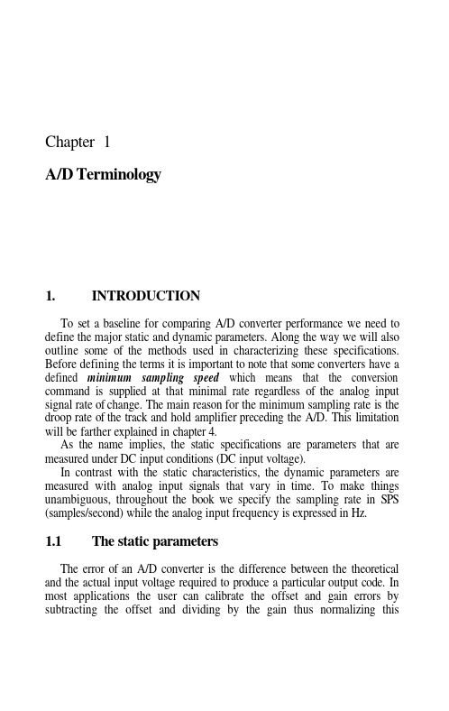
Chapter 1A/D Terminology1. INTRODUCTIONTo set a baseline for comparing A/D converter performance we need to define the major static and dynamic parameters. Along the way we will also outline some of the methods used in characterizing these specifications. Before defining the terms it is important to note that some converters have a defined minimum sampling speed which means that the conversion command is supplied at that minimal rate regardless of the analog input signal rate of change. The main reason for the minimum sampling rate is the droop rate of the track and hold amplifier preceding the A/D. This limitation will be farther explained in chapter 4.As the name implies, the static specifications are parameters that are measured under DC input conditions (DC input voltage).In contrast with the static characteristics, the dynamic parameters are measured with analog input signals that vary in time. To make things unambiguous, throughout the book we specify the sampling rate in SPS (samples/second) while the analog input frequency is expressed in Hz.parameters1.1 ThestaticThe error of an A/D converter is the difference between the theoretical and the actual input voltage required to produce a particular output code. In most applications the user can calibrate the offset and gain errors by subtracting the offset and dividing by the gain thus normalizing this2Chapter1deviation. The normalized error is called the relative error (as opposed to the absolute error, which is the actual measured difference).Following is a list of terms that define converter static errors.1.1.1Offset ErrorThis is the difference between the theoretical and actual input voltage required to obtain the transition from code 0000..00 to code 0000..01.It should be noted that some manufactures define the offset at the mid-scale of the converter’ range (when the input is symmetric around 0V). The assumption is that the converter’ transfer curve is described by a straight:where G is the slope of the line and is the offset.1.1.2Gain ErrorThis parameter indicates the slope difference between the lines connecting the theoretical and actual transitions of the full scale extremes - transition 0000..00 to 0000..01 and transition 1111..10 to 1111..11. Theoretically the line should span from 0.5 LSB above zero where the first transition occurs and 1.5 LSB below the full scale (remember that the last code 1111..11 occurs 1 LSB below full scale and the last code transition is 0.5 LSB below that point). The ratio of the span between the first and the last actual codes and the ideal difference is the gain error (usually expressed as a percentage of full scale).1.1.3Integral Linearity Error ( ILE )This is the worst case deviation of codes from a straight line connecting the ends of the full scale (from -FS to +FS).Figure 1 – 1 is an example of the transfer curve for a 3-bit A/D converter. The dotted line represents the theoretical transfer curve of the converter. The heavier line represents the actual input voltage required to obtain the output code transitions shown on the Y-axis. Since we are considering a 3-bit converter, we expect eight output levels from 000 to 111. Counting from one end of the full scale to the other we observe seven transition points or for the general case If we assume in our example that the full-scale range is 2V, the corresponding LSB weight is 0.25V(=2V/8) Next, we illustrate the end-point normalization process for the ILE calculation as it applies to our example. The data is presented in table 1 – 1. This end-point normalization process defines the equation that connects the full-scale extremes as follows:A/D Terminology3isthe normalized voltage,input voltage,themeasuredwhere isvoltage required for that transition.theoreticaland istheFigure 1-1. Transfer curve for a typical A/D - Digital out vs. analog inThis equation defines a gain – G – and an offset – OS – for the transfer curve. Substituting and extracting the equation for the normalized voltage we obtain:and4Chapter 1The normalization process just defined is called end-point normalization since it uses the end points of the full scale for the calculation. Note that by definition the error at the ends is always zero.The normalized linearity of the device is also shown in table 1-1:Based on the previous definition and equation 1.2 we calculate the gain error to be:resulting in a gain error of approximately 3.3%. The offset – OS – is calculated to be 0.10833 V or an offset error of 0.433 LSBs. The maximum difference from the end point line occurs at the transition 100 to 101 with a deviation of 0.224138 V (=0.896LSBs).Some manufacturers specify the ILE as a line of the form that best approximates the input-output transfer curve in terms of best square fit .The idea is to select a line,which minimizes the square of the error for each of the M data points:where and are the slope and intersection of the linear regressionsuch that the deviation from the line – S -is minimized. In this case the end points of the full scale do not have zero error. Applying this definition to our example and using the theoretical points as reference we calculate the best square fit: and The maximum ILE for theA/D Terminology5 best square fit occurs at the last code (110 to 111) and is –0.135714V or -0.543 LSB s. The last results can be calculated using any mathematical program that has routines for linear regression.Obviously the two normalization techniques just defined are significantly different from each other. Using the end point linearity definition the ILE is almost LSB while the ILE for the best-fit definition is of 0.54 LSB. This illustrates that the lack of standards in converter specifications may mislead the user in perceiving wide variations in performance due to “specmanship”.Lastly, since the ILE is an indication of the converter transfer characteristics under dynamic conditions it is evident that the best square fit is a better indicator of the converter’s harmonic distortion (see section - How does the linearity affect the converter dynamic behavior? - below)1.1.4Differential Linearity Error(DLE)This is the actual difference between two adjacent codes minus 1LSB.In an ideal A/D adjacent code transitions are 1LSB apart resulting in a DLE of 0 LSBs (DLE = 1LSB – 1LSB = 0LSB). A converter is called monotonic when it exhibits an increasing output code for an increasing input voltage. When the DLE is non-negative the monotonicity of the converter is guaranteed.The simplest method used to check the static performance of an A/D is shown in figure 1 – 2.The test is performed as follows: a linear input voltage with an amplitude equivalent to a fraction of the full-scale range (10-20 LSBs) is supplied to the device under test (DUT). This linear ramp must have the means of being shifted from one end of the full-scale to the other. B y changing the ramp’s offset, all code transitions can be observed. Using this test method, we notice that the output signal is not a straight line from –FS to +FS but rather a collection of segments shifted in amplitude - see figure 1 – 3. This is equivalent to a modulo operation - the pattern of eight steps repeats and it represents the residue of the overall full scale to the length of the segment presented. As shown in figure 1 – 3 the last three LSBs are utilized to restore the digital output into an analog voltage – constituting a D/A converter.The D/A performs its conversion by transforming the digital voltage of the bit into a binary weighted current. The three currents are summed into obtaining the D/A output voltage.The reconstructing D/A amplitude accuracy is not important in this case since the error of interest is shown along the X-axis of the display. Thus, if the resistors are not related in an exactly binary fashion the output shows unequal step heights in the reconstruction on the Y-axis.6Chapter1Figure 1-2. Static test for an A/D converterFigure 1-3. A 3-bit reconstruction of the digital output of an A/DA/D Terminology 7In a typical converter, not all the codes are equal in width. This width variation reflects the linearity errors. The linearity errors of an A/D converter are therefore shown along the X-axis.Figure 1 – 3 also shows that the code transitions as displayed on an oscilloscope are not very crisp and well defined. These uncertainties (gray areas) on the X – axis represent a dynamic error called jitter (see also dynamic parameters below).1.2 Thedynamic parametersThe dynamic errors of an A/D converter are the result of its behavior under input transient conditions. These errors reflect insufficient bandwidth, slew-rate limitation or settling time of the analog signal path. They are an inevitable consequence of the design tradeoffs between speed, resolution and power conservation. Bandwidth limitation is a dynamic deficiency, whichnonlinear components in the circuit (such as capacitance voltage coefficients, dielectric absorption, etc.).1.2.1Total Harmonic Distortion (THD)This is the ratio of the square root of the sum of the squares of the first most significant harmonics (usually from second to the fifth) to the fundamentalThisparameter is generally expressed in dB.output signal1.2.2Signal-to-Noise Ratio (SNR)This is the ratio of the remaining harmonics (not accounted for in the THD) to the fundamental. This parameter is usually expressed in dB.8Chapter11.2.3Signal-to-Noise and Distortion Ratio (SINAD or TDE for TotalDynamic Error)TDE is the ratio of all harmonics to the fundamental. This parameter is usually expressed in dB.Since the numerator is usually smaller than the denominator, this is a negative number.SINAD reflects the ratio of signal to noise and distortion. Since the signal is in the numerator and the noise and distortion are in the denominator this represents the reverse ratio relative to TDE. Therefore the SINAD and TDE are equal in magnitude, and have opposite sign.The relation between TDE and THD and SNR is given by:1.2.4 Spurious-FreeDynamic RangeThis is the difference (in dB) between the RMS input signal andthe highest frequency spur at the output of the A/D. Figure 1 - 4 shows an example of how SFDR is measured in an FFT test. In our example the SFDR is approximately 50 dB.Note: In all equations above the assumption is that the fundamental frequency resides in the first bin of the spectrum. The FFT program in figure 1-11 is set to assure that this is indeed the case.A/D Terminology9rFigure 1-4. Spurious Free Dynamic Range (SFDR) definition1.2.5Aperture uncertaintyDue to noise, the A/D converter response to the conversion command does not occur at a known time instance. Aperture uncertainty or jitter is definedas the short-term, non-cumulative variation of the significant instants of the sampling signal from their ideal position in time. The error manifests itself as an edge variation of the sampling signal relative to the analog input. Agraphical illustration of this phenomenon is shown in figure 1 – 5. Sincemost high-speed converters employ a track and hold amplifier in front of theA/D, figure 1 – 5 refers to the two regions of operation as the track and holdregions. The sampling instance in figure 1-5 occurs on the falling edge of the track/hold command when the analog voltage is being held prior to being processed by the A/D converter. The highest probability of the sampling edge is shown as the darker region.There are two reasons for this uncertainty – amplitude noise causingthreshold of the sampling device to fluctuate and phase instability of the sampling clock.10Chapter1Figure 1-5. Jitter caused timing errorWhen dealing with high input frequencies the jitter causes noise-like distortions to the sampled signal.Since aperture uncertainty is a random, noise-like phenomenon, it contributes to a reduction in SNR. References 33 and 37 analyze the contribution of aperture uncertainty to the reduction of SNR.The following equation predicts the relation between aperture uncertainty and SNR:In the equation represents the RMS aperture jitter and f is the input frequency. A graph showing SNR degradation due to aperture uncertainty is shown in Figure 1- 6.A/D Terminology11Figure 1-6. SNR reduction due to aperture jitterThe graph shows for example that an A/D with an aperture uncertainty of 50 psec RMS error, tested at an input frequency of 10 MHz will be limited to an SNR of approximately 50 dB. Thus if we test a 10 bit A/D that is expected tohave SNR of 62 dB due to quantization error, it is important to limit the jitterto less than 10 psec RMS error:1.2.6Frequency aliasingThis is a phenomenon that is a direct artifact of the sampling process. The Nyquist sampling theorem requires that a continuous bandwidth-limitedthis input signal with frequency limited to is sampled at a rate If12Chapter1 condition is n o t observed,the Fourier transform of the sampled signal gets distorted. This occurs because frequency components exceeding the Nyquist frequency are folded back into the input band. This phenomenon makes the reconstruction of the input signal impossible. To mitigate aliasing, it is important to choose the relationship of input to sampling frequency carefully (29,39).A graphical illustration of the aliasing phenomenon is shown in figure 1 – 7.Figure 1-7. Frequencies above Fs/2 are aliased due to the sampling process Given the sampling frequency of the converter (Fs) and the analog input frequency the aliased frequency can be found as follows:i. calculate Name the residue of the divisionbelocated atii. if then the aliased frequency willotherwiseiii. will be located at RFor example if the converter sampling frequency is 1GSPS and the input frequency is 450 MHz, the fundamental frequency of the reconstructed output is found at 450 MHz. The second harmonic is expected to be at 900 MHz. Since this frequency is higher than the Nyquist frequency (=500 MHz) and the calculated R=900 MHz it means that the second harmonic will beA/D Terminology13 aliased. The corresponding frequency for the second harmonic will be found at:The third harmonic will be found at 350 MHzand therefore the tone will be found at 350 MHz.1.2.7 How does the linearity affect the converter dynamic behavior?The sheer operation of the A/D transforming a smooth input ramp into discrete levels through the quantization process creates harmonics. This is known as quantization noise. For a perfectly linear A/D, the quantization noise limits the SNR performance level to:That is, if the input signal extends to the full-scale range of the converter the noise caused by the quantization process results in dB below the fundamental. In the equation, N represents the number of bits. For example in a 10-bit device, the noise floor is 61.96 or approximately 62 dB bellow the RMS value of the input signal. (9,11,12,14,17,19).Excluding dynamic limitations of the converter such as slew-rate limitations, the Integral Linearity Error (IL or INL) is the major cause of harmonic distortion (THD). The reason is that when a sinusoid is passed through a nonlinear transfer function it gets distorted creating harmonic tones at the output. Usually the INL of an A/D converter is fairly smooth resulting therefore in low order harmonics. The differential nonlinearity of the A/D on the other hand causes high frequency harmonics that are accounted for in the SNR factor. The reason is that unlike the smooth integral nonlinearity, the DLE represents abrupt adjacent transition in the transfer function in the time domain. This is equivalent to a high frequency harmonic content in the frequency domain and thus, results in high order harmonics. Since high harmonics are accounted for in the SNR ratio, DNL cause a reduction in signal-to-noise ratio.The parameter that measures all nonlinearities of the A/D in aggregate is the TDE or SINAD (signal to noise and distortion) since it encompasses both THD and SNR. Some manufacturers specify an additional parameter called ENOB (effective number of bits). This figure measures the equivalent number of bits in an A/D as a function of input frequency. In effect this is the same equation as the one predicting the noise floor where the number of bits of the converter – N is replaced by ENOB:14Chapter1The difference between the equations is in the fact that ENOB is always specified as a function of frequency. For example a device withhas approximately 10 effective bits at the specified frequency.1.2.8 Converter resolution effects on Spurious Free Dynamic Range The SFDR is a critical parameter especially in communication systems. An analysis of its dependency on the number of bits of the converter has been investigated in references 33, 37 and 53 and it is shown to be: The highest harmonic is proven to occur at harmonicfor a converter limited by quantization noise.In other words the largest harmonic of an N bit A/D is lower than the fundamental by 9N dB (assuming a sinusoidal full-scale input signal). This equation predicts that each increase in the number of bits results in a 9-dB reduction in harmonics. An intuitive explanation for this effect is as follows: going from N to bits reduces the quantization noise by a factor of 2 (6 dB). In addition, since the quantization frequency is doubled for each additional bit, the frequency of the error is increased. Mathematically, Parseval’s formula tells us that the power is conserved in either the time or frequency domain and therefore the doubling of the frequency results in a 3-dB reduction in the harmonic magnitude. Ordinarily converters are not perfectly linear and thus SFDR is limited by lower order harmonics than predicted by the equations above.Let us summarize the A/D converter errors and their characteristics.The static parameters: offset, gain, INL, DNL are the easiest to test. These parameters are measured under DC input conditions and therefore are constant for a given converter. Figure 1 – 2 illustrates a way of evaluating these DC characteristics and additional methods are described in the references 9,15,18,32.The dynamic test methods for evaluating SNR, THD, SFDR, SINAD (TDE) are discussed at length in references 11, 12, 13, 14, 15, 17, 18, 19, 27, 28, 29, 30, 32, 37 and 38. The dynamic tests however are more elaborate and require significantly more care to accomplish than the static measurements.A/D Terminology15The dynamic performance of the A/D analyzed in the following chapters will underline the importance of certain device parameter on the dynamic performance of the entire A/D.The two test methods available for dynamic A/D evaluation can be categorized as follows:• the beat and envelope tests which are coherent tests and• the noncoherent windowed testsA common setup used for A/D coherent dynamic test is shown in figure1-8.Figure 1-8. Dynamic A/D test set-upIn the beat test method the sinewave-input signal is offset in frequency from the sample frequency. The beat frequency is selected such that on successive cycles of the sampling signal, the output “walks” through the input signal. When the reconstructed output signal is analyzed, the beat frequency is observed. A graphical example of beat frequency test is shown in figure 1-9:16Chapter1Figure 1-9. Dynamic "beat frequency" testThe test can be performed to observe differential or integral linearity as a function of the converter’s input frequency. In this case the samples are taken such that adjacent samples are only one LSB apart from each other. The frequency required for this test is (31):beat frequency and N is thethewhere is the sampling frequency, isconverter’s number of bits. For example if the device under test is a 10 bit converter with a sample rate of 10 MSPS, then the beat frequency required for 1 LSB change on successive samples is calculated to be 3.108 kHz from the equation above. Since each adjacent sampled point is expected to be1LSB away from the previous sample the ILE and DLE can be tested as a function of input frequency.This test is limited to multiples of the beat frequency but requires no special care regarding frequency spillage, which will be explained below.A variation of the beat test method is the envelope test. This method is more demanding on the converter in the fact that adjacent samples of the input are taken on opposite ends of the full scale. Thus the input signal is tested for example at the positive full scale, followed immediately by a sample at the negative full scale.B y making the sample frequency slightly offset from the Nyquist rate this method ensures that the samples are taken on alternate half cycles of the input signal. In performing this test, the A/D converter can be tested during slew-rate conditions and pushed to the settling limit of various internal blocks of the converter.The envelope and beat test methods are called coherent test methods.This is a result of the very tight dependence between the sampling frequency and the analog input frequency. Unless these two signals are completely synchronized during the test (as illustrated in figure 1 – 8), they introduce noise similar to the aperture uncertainty of the converter itself. In fact the jitter between the input and sampling signal will RSS (square root of the sum of the squares) with the aperture uncertainty of the converter (assuming no correlation between the two).In contrast to the beat and envelope methods, that guarantee no frequency spillage effects, the noncoherent test methods require very careful choice of filters prior to the FFT calculations.To understand this problem let us consider how the sheer action of sampling of a continuous time signal affects the Fourier transform.When the Fourier transform of the continuous time signal is known, the Fourier transform of the discrete samples can be obtained by the followingoperations (39):1. transformation of the frequency axis according to the relation2. multiplication of the amplitude axis by a factor 1/T3. summation of an infinite number of replicas of the original spectrum,shifted horizontally by integermultiples of the sampling frequency The result of the summation gives a periodicity in with the period of Therefore the sampling in the time domain results in periodicity in the frequency domain. The filter’s function is to reduce the error caused by the sampling process. The main focus in Fourier analysis is the determination of the Fourier transform of a signal f(t) in term ofthe segment:A/D Terminology 1718Chapter 1In effect this represents the time window during which we look at the signal (42). By definition, we observe the A/D output during a finite time interval. A rectangular window in the time-domain is such that it has a value of 1 inside the window and 0 outside the observation time. In the frequency domain, the rectangular window is the familiar sin(x)/x of a rectangular pulse. To express mathematically the limited observation time we multiply a rectangular pulse equal to the observation time with the time varying digital output code. The multiplication between the finite observation time and the output of the A/D in the time domain corresponds to a convolution operation in the frequency domain.If the A/D output does not contain an integer number of cycles during the observed time-window the result will be a leakage error in the frequency domain .The leakage error comes about because the A/D data is not harmonically related to the window length. Adjusting the window to include an integer number of cycles can eliminate this error. The form that the leakage takes depends on the shape of the window. B y changing the window shape in the time domain and reducing the discontinuities at its edges we can significantly reduce the leakage.Several windows are classically used for the non-coherent test (39). Their main characteristics are outlined below:•Rectangular filter (with side lobes of –13.5dB)(39,43)• B artlett window (with side lobes of –27dB)(39)•Hann window (with side lobes of –32dB)(39,43)• Hamming window (with side lobes of –43 dB) (39,43)•Blackman window (with side lobes of –57dB)(39)•Kaiser filters (with side lobes -30to -90dB depending on thefactor)(39)•Dolph filters (with side lobes -40to -80dB depending on thefactor)(39)The rectangular window is the standard acquisition window with a weight of 1 inside the window and zero outside the window.The Hamming window is a combination of cosine added to a pedestal and so on. In all above filters the intent is to minimize the width of the main lobe and reduce the size of the side lobes with respect to the main lobe in the frequency domain. In general,the greater the window’s bandwidth, the less resolution it provides. On the other hand, as the side lobes decrease, the filter selectivity increases - the ability to distinguish adjacent frequency components. A discussion of these filters is beyond the scope of this book.A/D Terminology 19The rectangular window while not the best in the frequency domain due to limited attenuation of its side lobes ( sin(x) / x), is the easiest to visualize. There is no weighing function that is given to the various time-data and therefore all points have the same weight. This is different than the other filters mentioned above where each time-data-point is given a differentaccomplish the weight through the multiplication operation to windowing function (39 and 43).1.2.9 Rectangular window – an exampleLet us illustrate how the width of rectangular filter can affect the results of the FFT test in a perfect A/D. In our example, we consider a perfect A/D with infinite resolution. The output of the converter is analyzed in a FFT using a 4K-point time record. The time record is then subjected to truncation of the tail data points and padded with zero (this is the operation of adding zeroes to the tail of the sequence). In other words the time record is shorten from 4K points one point at a time and the original data is padded with zeroes. This is equivalent to the shortening of the observation time Plotting the dynamic performance – TDE – as a function of the number of truncated tune records results in the graph outlined in figure 1 - 10.Figure 1-10. The truncation error caused by the rectangular window affects the Signal-to-Noise-and-Distortion (SINAD)20Chapter 1The same graph outlines as well the truncation error for a 1K FFT.Several things are evident in the graph:1. The slope of the graph isdB/decade. For a 4K FFT with a devicewith infinite resolution and with 0.1% zero padding thedB. This means that if four of the time data points are set to zero (0.1%of 4096 points) the performance is reduced to less than 9 effective bits!2. For a 1K point FFT with the same infinite resolution A/D, the SINAD is12 dB lower than the 4K FFT. Again with 0.1% truncation and zero padding limits the SINAD to approximately 42.6 dB (or less than 7effective bit performance).This example demonstrates the importance of careful choice in the number of data points for a noncoherent test of A/D and the result of such test when the data is truncated and zero padded. In general when a user is interested in improving the noise floor observability in any A/D converter the time domain record needs to be increased. The noise floor for such a converter isimproved to:where n is the number of time points and N is the converter resolution. In other words if a 12 bit converter is used and the expected quantization noise is d B than with 1024 time points for the FFT we can observe a noise floor of 101 dB Doubling the number of time points to 2048 further improves the noise floor by an additional 3 dB.1.3 The FFT analysisIn the following chapters, all the A/D considered are analyzed using an envelope test to achieve the required coherent test of the device. The resulting time data is subjected to an FFT test using a MATHCAD program.The FFT file is provided below in figure 1 - 11).The analysis proceeds as follows: the SPICE produced output file is transferred into a file called “FILENAME.DAT”. The data file is scanned by the MATHCAD program and examined for the FFT length (expected to be half as long as the number of time-data points). This also establishes the frequency number of bins (frequency resolution). The vector representing the time domain samples are expected in the first column of the data file (remember that Mathcad indexes from “0” not “1”) sothe first column of your data file is vector or in Mathcad terminology while the time data points are expected in By searching for the highest。
ADC种类及参数选择
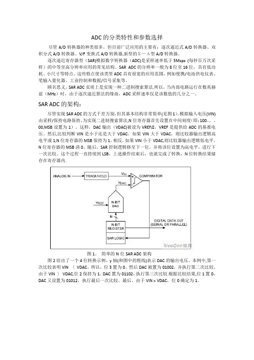
ADC的分类特性和参数选择尽管A/D转换器的种类很多,但目前广泛应用的主要有:逐次逼近式A/D转换器、双积分式A/D转换器、V/F变换式A/D转换器,新型的Σ—Δ型A/D转换器。
逐次逼近寄存器型(SAR)模拟数字转换器(ADC)是采样速率低于5Msps (每秒百万次采样)的中等至高分辨率应用的常见结构。
SAR ADC的分辨率一般为8位至16位,具有低功耗、小尺寸等特点。
这些特点使该类型ADC具有很宽的应用范围,例如便携/电池供电仪表、笔输入量化器、工业控制和数据/信号采集等。
顾名思义,SAR ADC实质上是实现一种二进制搜索算法.所以,当内部电路运行在数兆赫兹(MHz)时,由于逐次逼近算法的缘故,ADC采样速率仅是该数值的几分之一。
SAR ADC的架构:尽管实现SAR ADC的方式千差万别,但其基本结构非常简单(见图1)。
模拟输入电压(VIN)由采样/保持电路保持。
为实现二进制搜索算法,N位寄存器首先设置在中间刻度(即:100。
.. 。
00,MSB设置为1)。
这样,DAC输出(VDAC)被设为VREF/2,VREF是提供给ADC的基准电压。
然后,比较判断VIN是小于还是大于VDAC。
如果VIN大于VDAC,则比较器输出逻辑高电平或1,N位寄存器的MSB保持为1。
相反,如果VIN小于VDAC,则比较器输出逻辑低电平,N位寄存器的MSB清0。
随后,SAR控制逻辑移至下一位,并将该位设置为高电平,进行下一次比较。
这个过程一直持续到LSB。
上述操作结束后,也就完成了转换,N位转换结果储存在寄存器内.图1。
简单的N位SAR ADC架构图2给出了一个4位转换示例,y轴(和图中的粗线)表示DAC的输出电压。
本例中,第一次比较表明VIN 〈VDAC。
所以,位3置为0。
然后DAC被置为01002,并执行第二次比较。
由于VIN 〉VDAC,位2保持为1。
DAC置为01102,执行第三次比较.根据比较结果,位1置0,DAC又设置为01012,执行最后一次比较。
ADC性能参数及测试方法
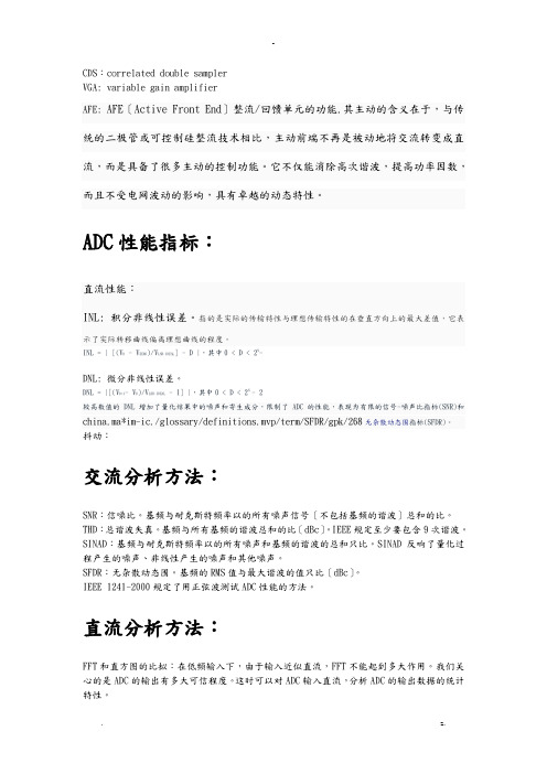
CDS:correlated double samplerVGA: variable gain amplifierAFE: AFE〔Active Front End〕整流/回馈单元的功能.其主动的含义在于,与传统的二极管或可控制硅整流技术相比,主动前端不再是被动地将交流转变成直流,而是具备了很多主动的控制功能。
它不仅能消除高次谐波,提高功率因数,而且不受电网波动的影响,具有卓越的动态特性。
ADC性能指标:直流性能:INL: 积分非线性误差。
指的是实际的传输特性与理想传输特性的在垂直方向上的最大差值,它表示了实际转移曲线偏离理想曲线的程度。
INL = | [(V D - V ZERO)/V LSB-IDEAL] - D |,其中0 < D < 2N-DNL: 微分非线性误差。
DNL = |[(V D+1- V D)/V LSB-IDEAL - 1] |,其中0 < D < 2N - 2较高数值的DNL增加了量化结果中的噪声和寄生成分,限制了ADC的性能,表现为有限的信号-噪声比指标(SNR)和china.ma*im-ic./glossary/definitions.mvp/term/SFDR/gpk/268无杂散动态围指标(SFDR)。
抖动:交流分析方法:SNR:信噪比。
基频与耐克斯特频率以的所有噪声信号〔不包括基频的谐波〕总和的比。
THD:总谐波失真。
基频与所有基频的谐波总和的比〔dBc〕。
IEEE规定至少要包含9次谐波。
SINAD:基频与耐克斯特频率以的所有噪声和基频的谐波的总和只比。
SINAD反响了量化过程产生的噪声、非线性产生的噪声和其他噪声。
SFDR:无杂散动态围。
基频的RMS值与最大谐波的值只比〔dBc〕。
IEEE 1241-2000规定了用正弦波测试ADC性能的方法。
直流分析方法:FFT和直方图的比拟:在低频输入下,由于输入近似直流,FFT不能起到多大作用。
我们关心的是ADC的输出有多大可信程度。
ADC基本参数
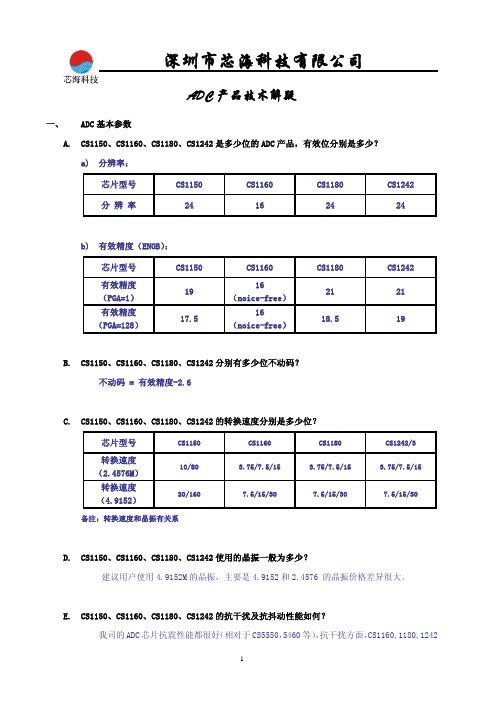
ADC产品技术解疑一、 ADC基本参数A.CS1150、CS1160、CS1180、CS1242是多少位的ADC产品,有效位分别是多少?a)分辨率:芯片型号 CS1150 CS1160 CS1180 CS1242分辨率 24 16 24 24b)有效精度(ENOB):芯片型号 CS1150 CS1160 CS1180 CS1242有效精度(PGA=1) 1916(noice-free)21 21有效精度 (PGA=128) 17.516(noice-free)18.5 19B.CS1150、CS1160、CS1180、CS1242分别有多少位不动码?不动码 = 有效精度-2.6C.CS1150、CS1160、CS1180、CS1242的转换速度分别是多少位?芯片型号 CS1150 CS1160 CS1180 CS1242/3转换速度(2.4576M)10/80 3.75/7.5/15 3.75/7.5/15 3.75/7.5/15 转换速度(4.9152)20/160 7.5/15/30 7.5/15/30 7.5/15/30 备注:转换速度和晶振有关系D.CS1150、CS1160、CS1180、CS1242使用的晶振一般为多少?建议用户使用4.9152M的晶振,主要是4.9152和2.4576 的晶振价格差异很大。
E.CS1150、CS1160、CS1180、CS1242的抗干扰及抗抖动性能如何?我司的ADC芯片抗震性能都很好(相对于CS5550,5460等),抗干扰方面,CS1160,1180,1242ADC产品技术解疑都容易通过国标,而CS1150 只是和积分电路相当,需要做处理后才能过emc测试。
F.CS1150、CS1160、CS1180、CS1242分别适用于那些工业及商业产品中?CS1150 适合于对emc要求不高的场合和低功耗的场合,例如低端计价秤,家用秤,消费类的产品上,CS1160,CS1180,CS1242适合做商用秤,工业用秤或者工业一起仪表行业,例如高端的计价秤,台秤,计数秤等。
- 1、下载文档前请自行甄别文档内容的完整性,平台不提供额外的编辑、内容补充、找答案等附加服务。
- 2、"仅部分预览"的文档,不可在线预览部分如存在完整性等问题,可反馈申请退款(可完整预览的文档不适用该条件!)。
- 3、如文档侵犯您的权益,请联系客服反馈,我们会尽快为您处理(人工客服工作时间:9:00-18:30)。
ADC测试参数定义、分析及策略之动态测试2007-11—08 10:50:21分类:前言混合信号技术给当今的半导体制造商们带来了很多新挑战,以前一些对数字电路只有很小影响的缺陷如今在嵌入式器件中却可能大大改变模拟电路的功能,导致器件无法使用。
为确保这些新型半导体器件达到“无缺陷”水平,需要开发新的测试策略、方法与技术。
本文将结合一个简单的混合信号器件——模数转换器(AD C)来对这些策略、技术与方法进行讨论,说明混合信号器件测试的步骤和方法。
有了这些基本认识后,就可将其扩展并应用到当前先进的嵌入式半导体器件中,如数字滤波器、音频/视频信号处理器及数字电位计等。
传统半导体器件测试包括基本参数测试(连续性、泄漏、增益等)和功能测试(将器件输出与给定输入相比较),混合信号测试还要再另外增加两个测试,即动态测试和线性测试.动态参数描述的是器件对一个特定频率或多频率时序变化信号的采样(从模拟信号中建立数字波形)和重现(利用数字输入建立模拟信号)能力。
线性参数则相反,描述的是器件内在特性,主要关注数字和模拟电路之间的关系.下面将对这两种特性分别作详细说明。
动态测试模数转换器的动态特性有时也称作传输参数,代表器件模拟信号采样和输入波形的数字再现能力,信噪比(S NR)、总谐波失真(THD)及有效位数(ENOB)等指标可使制造商对器件输出的“纯度”和数字信息精度进行量化。
新型动态测试技术产生于上世纪80年代,主要围绕数字信号处理和傅立叶变换,将时域波形和信号分别转换为频谱成分.这种技术可以同时对多个测试频率进行采样,效率和重复性非常高.图1是对一个普通ADC 器件进行快速傅立叶变换(FFT)测试的示意图,图中可以看到模拟信号在时域内转换成数字代码,然后用傅立叶变换转换成频谱。
对ADC输出进行傅立叶分析可提供宝贵的性能信息,但如果测试时条件设置不当得到的信息也会毫无意义。
为了从器件输出信号的傅立叶分析中提取有意义的性能参数,在讨论FFT结果之前首先需要考虑测试条件,其中包括输入信号完整性、采样频率、一致性及系统测量误差(假频、量化及采样抖动误差)。
图1 ADC器件傅立叶测试示意图◆输入信号对于模数转换器来说,输入信号的“纯度”会影响数字输出的性能.输入信号中的耦合噪声将转换为输出信号数字噪声,如果输入信号中有太多噪声和失真,ADC性能实际上会被测试条件所掩盖。
输入信号的精度和纯度最终取决于器件的转换分辨率,一般来说测试设备的精度要比被测器件高10倍以上。
另外可以考虑在输入端使用滤波器,除去输入信号之外的噪声和失真。
◆采样与一致性采样频率是采样时间的倒数,如果采样数据点选择正确,一个无限时序变化信号可用有限几个数据点来表示。
通过奈奎斯特采样间隔定理,即采样频率必须是被测信号频率的两倍以上,我们可以获得正确的采样频率范围,利用采样点再现输入信号。
在我们所举例子中,ADC必须以输入频率两倍以上的频率“运行”或采样,以便正确地数字化再现出输入信号,得到有效动态测试结果。
一致性是动态测试第二个关键的部分,当能对测试信号的生成与采样进行控制时,它可以提供很多东西。
一致性采样主要是为了保证采样数据包含完整的输入周期描述信息,使得在有限的样本中收集到尽可能多输入信息。
一致性采样定义了测试频率(Ft)、样本大小(M)、采样频率(Fs)以及测试周期(N)之间的关系,如式(1)所示:M/Ft=N/Fs 式(1)这里的M和N为互质数。
另外,一致性采样还可以保证傅立叶变换将采样数据的频率成分放入离散频段中。
◆量化、假频与采样抖动量化误差指的是从时序变化信号中可分离出的最小量值信息,以我们讨论的ADC测试为例,量化误差就是最小步距代表的电压,或建立输入测试信号的模拟信号源最小分辨率。
假频是由采样产生的,它将高频信号认作低频信号。
实际上当采样频率小于信号频率两倍时,采样周期即已违反了奈奎斯特采样规定,对高频信号采用低采样率的结果就好像它是一个低频信号。
抖动误差是指系统输入或采样能力与期望值之间的差异或偏离,换句话说,本来一个有一定幅度的信号预计在时间X产生,但由于抖动误差会使信号比预期的时间提前或推迟出现;同样抖动误差也可能在采样时产生,原来规定在时间X采集数据但实际却比预期时间提前或推迟。
量化误差、抖动误差和假频都会使输入信号失真,在频谱上出现错误信息。
如果测试条件都设置正确,同时也遵守采样规则,那么时基采样信号经傅立叶变换后的频率部分将提供重要的器件性能参数。
图2是一个典型的傅立叶变换图,突出的部分是基本频率,定义为器件输入频率,在这个例子中是一个1kHz正弦波,图中也显示了在基本频率倍频上出现的谐波频率和最大幅值。
对于我们讨论的A DC器件,从频谱可以算出五个重要动态传输特性,分别是信噪比(SNR)、总谐波失真(THD)、无杂散动态范围(SFDR)、信号与噪声失真比(SINAD)以及有效位数(ENOB)。
图2 傅立叶变换图·信噪比(Signal to Noise Ratio,SNR)信噪比是输入信号和噪声(不包括任何谐波以及直流) 的功率比,是定义器件内部噪声大小的基本参数。
SN R定义的详细描述如式(2)所示:式(2)理论上ADC的信噪比范围取决于系统的位数,式(3)是理想的N bit ADC的理论SNR计算公式:SNR=6.02N+1。
76dB 式(3)这里N代表位数。
系统内部噪声会使偏离或SNR大于理论值范围,可能造成误差的原因包括:器件量化误差、器件内部噪声和驱动/采样源产生的非线性噪声(应用噪声).量化噪声关系到转换器的分辨率,转换器内的噪声主要是和输入比较器的完善程度有关。
附声卡中对SNR的定义:SNR是对声卡抑制噪音能力的一个评价。
声卡处理的是对我们有用的音频信号,而噪音是指我们不希望有的音频信号,通常是一些规律且难听的声音,是背景噪声(由机箱内电磁干扰产生)与声卡各部件在工作时产生的“杂音”的综合,声卡应该尽量屏蔽和减少这些噪音的出现与功率(音量)。
在没有出现饱和与截止情况下,有用信号功率与噪音信号功率的比值就是SNR,单位为dB.SNR值越高说明声卡的滤波效能越好,声音听起来也就越清晰。
按照微软在PC98中的规定,声卡的SNR值必须不低于80dB。
·无杂散动态范围(Spurious-free Dynamic Range,SFDR)无杂散动态范围能对系统失真进行量化,它是基本频率与杂波信号最大值的数量差。
杂波通常产生于各谐波中(虽然并不总是这样),它表示器件输入和输出之间的非线性。
偶次谐波中的杂波表示传递函数非对称失真,一个“给定”的输入信号应该产生一个“给定”的输出,但由于系统非线性,实际输出并不等于预期值,当系统接收到大小相等极性相反的信号时,得到的两个输出不相等,这里的非线性就是非对称的。
奇次谐波中的杂波表示系统传递函数的对称非线性,即给定的输入产生的输出失真对正负输入信号在数量上都是相等的。
附:在频域中,SFDR是衡量线性特性的有效方法。
如果单音正弦信号加到输入,SFDR定义在一定频率范围内的信号与第二大频率成分的功率差。
在大多通信应用中,输入是多音信号,信号由幅度、相位、和频率不同的多个信号组成.测量SFDR时将引起一些混淆,有时更好是用称之为多音功率比(Multi—tone Power Rati o,MTPR)进行测量,MTPR定义为单音载波与失真的功率比。
我们在多个频率施加一定数量的等幅但相位不同的信号.在某点测量该点的输出和该点失真的功率。
注意这有几个参数影响MTPR,例如单音幅度、挑选的单音频率、单音数量。
在不同情况下,得出的MTPR也不同。
当单音数量增加,将形成一个高的峰值.高峰值可能使放大器饱和并使DAC超出范围。
我们用峰值/平均值比(PAR)或峰值因子,测量输入信号的峰值与有效值功率,对单音正弦信号PAR=A2/(A/sqrt(2))2=2。
有时PAR也定义为均方根功率比.如果输入单音幅度相等,单音数量和相位决定PAR.多个信号输出的SFDR见式(4):SFDR=6.02×N+4。
77-10×log(PAR) 式(4)高速DAC根据奈奎斯特采样定理,如果采样时钟为fs,信号带宽为fn=fs/2,但SFDR可能比较差。
提高SFDR的一个有效途径是采用比奈奎斯特频率小的带宽,当信号带宽为fB,定义过采样率OSR=fs/fB.单个信号输出的SFDR如式(5)所示:SFDR=6。
02×N+1。
76+10×log(OSR)式(5)采样时钟的抖动影响信号的抖动,并且时钟本身存在杂散,这些杂散通过电路耦合到输出,降低信号质量.·总谐波失真(Total Harmonic Distortion,THD)总谐波失真是输入信号与系统所有谐波的总功率比,它可提供系统对称和非对称非线性产生的总失真大小,用以表达其对信号的谐波含量的作用或者影响。
式(6)附:谐波失真是指音箱在工作过程中,由于会产生谐振现象而导致音箱重放声音时出现失真。
尽管音箱中只有基频信号才是声音的原始信号,但由于不可避免地会出现谐振现象(在原始声波的基础上生成二次、三次甚至多次谐波),这样在声音信号中不再只有基频信号,而是还包括由谐波及其倍频成分,这些倍频信号将导致音箱在放音时产生失真.总谐波失真是指用信号源输入时,输出信号(谐波及其倍频成分)比输入信号多出的额外谐波成分,通常用百分数来表示.一般来说,1MHz频率处的总谐波失真最小,因此不少产品均以该频率的失真作为它的指标。
所以测试总谐波失真时,是发出1MHz的声音来检测,并希望这个值越小越好。
·信号与噪声失真比(Signal to Noise And Distortion,SINAD)信号与噪声失真比SINAD是输入信号和所有输出信号失真功率(包括谐波成分,不包括直流)比,它测量的是输出信号所有传递函数非线性加上系统所有噪声(量化、抖动和假频)的累积效果.其定义如下:式(7)在完美的转换器中,SINAD和SNR是相同的。
SNR是转换器所能达到的理想状态,SINAD是反映转换器实际性能参数的指标,当然,我们希望SINAD越接近SNR越好。
·有效位数(Effective Number of Bits,ENOB)有效位数ENOB是在ADC器件信噪比基础上计算出来的,它将传输信号质量转换为等效比特分辨率。
实际上系统噪声使输出信号失真,失真大小就反映在信噪比上.ADC的比特分辨率可以用来计算给定器件的理论信噪比,反过来也成立,所以器件的信噪比测量值也可用来计算有效器件比特分辨率。
所有噪声源和器件的不精确性合在一起,可以转化为量化误差与有效器件分辨率。
让我们再次重新温习一下在ADC中的两个重要的概念:SINAD表示ADC的信噪失真比,指ADC满量程单频理想正弦波输入信号的有效值与ADC输出信号的奈奎斯特带宽内的全部其它频率分量(包括谐波分量,不包括直流分量)的总有效值之比。
